Embed Size (px)
Citation preview
TECHNICAL REPORT AD ___________________ NATICK/TR-08/013
EFFECT OF WOOL COMPONENTS IN PILE FABRICS ON WATER VAPOR SORPTION, HEAT RELEASE AND
HUMIDITY BUFFERING
by Phillip Gibson
May 2008 Final Report May 2007 – July 2007
Approved for public release; distribution is unlimited
U.S. Army Natick Soldier Research, Development and Engineering Center Natick, Massachusetts 01760-5020
REPORT DOCUMENTATION PAGE Form Approved
OMB No. 0704-0188 Public reporting burden for this collection of information is estimated to average 1 hour per response, including the time for reviewing instructions, searching existing data sources, gathering and maintaining the data needed, and completing and reviewing this collection of information. Send comments regarding this burden estimate or any other aspect of this collection of information, including suggestions for reducing this burden to Department of Defense, Washington Headquarters Services, Directorate for Information Operations and Reports (0704-0188), 1215 Jefferson Davis Highway, Suite 1204, Arlington, VA 22202-4302. Respondents should be aware that notwithstanding any other provision of law, no person shall be subject to any penalty for failing to comply with a collection of information if it does not display a currently valid OMB control number. PLEASE DO NOT RETURN YOUR FORM TO THE ABOVE ADDRESS. 1. REPORT DATE (DD-MM-YYYY) 19 - 05 - 2008
2. REPORT TYPE Final
3. DATES COVERED (From - To) May 2007 – July 2007
4. TITLE AND SUBTITLE
5a. CONTRACT NUMBER
EFFECT OF WOOL COMPONENTS IN PILE FABRICS ON WATER VAPOR SORPTION, HEAT RELEASE AND HUMIDITY BUFFERING
5b. GRANT NUMBER
5c. PROGRAM ELEMENT NUMBER 0602786A
6. AUTHOR(S)
5d. PROJECT NUMBER BA07PRO010
Phillip Gibson
5e. TASK NUMBER
5f. WORK UNIT NUMBER
7. PERFORMING ORGANIZATION NAME(S) AND ADDRESS(ES)
8. PERFORMING ORGANIZATION REPORT NUMBER
NATICK/TR-08/013
9. SPONSORING / MONITORING AGENCY NAME(S) AND ADDRESS(ES) 10. SPONSOR/MONITOR’S ACRONYM(S) 11. SPONSOR/MONITOR’S REPORT NUMBER(S) 12. DISTRIBUTION / AVAILABILITY STATEMENT Approved for public release; distribution is unlimited.
13. SUPPLEMENTARY NOTES
14. ABSTRACT This report describes an experimental approach for and results from measurements of the effect of wool fibers on thermal effects related to moisture sorption and desorption for several wool-containing fabrics, pile fabrics, and wool blend materials. Commercially successful polyester pile fabrics are undergoing further development to add wool fibers into one or more of the pile faces to take advantage of the natural thermal and water vapor regulation properties of wool. Wool clothing actively generates heat when moved from a warm and dry indoor environment to cold and wet outdoor conditions. This is due to the readjustment of water vapor content within wool fibers to maintain equilibrium with the local microclimate.
15. SUBJECT TERMS
16. SECURITY CLASSIFICATION OF:
17. LIMITATION OF ABSTRACT
18. NUMBER OF PAGES
19a. NAME OF RESPONSIBLE PERSON Phillip W. Gibson
a. REPORT UNCLASSIFIED
b. ABSTRACT UNCLASSIFIED
c. THIS PAGE UNCLASSIFIED
UU 24
19b. TELEPHONE NUMBER (include area code) 508-233-4273
Standard Form 298 (Rev. 8-98) Prescribed by ANSI Std. Z39.18
U.S. Army Natick Soldier Research, Development and Engineering Center (NSRDEC) Macromolecular Science and Engineering Team ATTN: AMSRD-NSR-WS-CM Natick, MA 01760-5020
WOOL TEXTILES SORPTION HEAT FLUX HYGROSCOPICITY FIBERS SENSORS HUMIDITY DURABILITY WATER REPELLENTS FABRICS COMFORT CLOTHING WATER VAPOR DWR(DURABLE WATER REPELLENT)

ii
This page intentionally left blank
iii
Table of Contents
List of Figures..................................................................................................................iv
Preface............................................................................................................................ v
1. Introduction ................................................................................................................ 1
2. Materials..................................................................................................................... 5
2.1 Knit Fabrics........................................................................................................... 5
2.2 Fleece Fabrics ...................................................................................................... 5
3. Experimental Method ................................................................................................. 6
4. Results ........................................................................................................................ 9
4.1 Effect of Wool Content on the Knit Fabrics ........................................................... 9
4.2 Effect of Fabric Orientation on Knit and Fleece Fabrics...................................... 11
4.3 Effect of Durable Water Repellent Treatment on the Bi-Faced Fleece Fabric .... 13
5. Conclusions.............................................................................................................. 14
6. References............................................................................................................... 15
iv
List of Figures
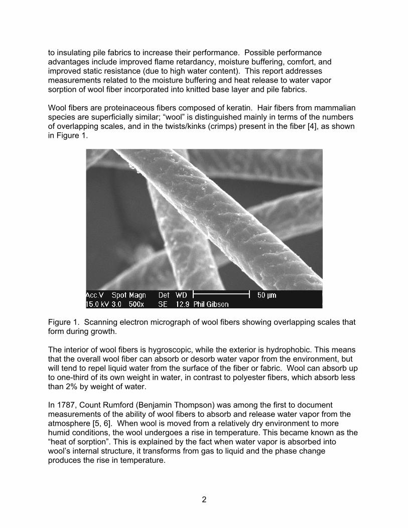
Figure 1. Scanning electron micrograph of wool fibers showing overlapping scales that form during growth. ......................................................................................................... 2
Figure 2. Experimental arrangement for measuring fabric temperature during changes in environmental relative humidity. .................................................................................. 3
Figure 3. Temperature change in wool fabric due to water vapor sorption..................... 3
Figure 4. Typical experimental and modeling results for water vapor sorption of hygroscopic fibers used in clothing apparel [9]................................................................ 4
Figure 5. Test cell setup to observe temperature and heat flow for fabrics subjected to a step change in relative humidity. ..................................................................................... 7
Figure 6. Detail of test cell connected to humidity and gas flow system in environmental conditioning box. ............................................................................................................. 7
Figure 7. Heat flux sensor and thermocouple secured to solid rubber sheet.................. 8
Figure 8. Heat flux, temperature, and humidity measurements from flow cell under step changes in relative humidity. ........................................................................................... 9
Figure 9. Relative temperature change from ambient temperature underneath the fabrics during step changes in humidity. ....................................................................... 10
Figure 10. Effect of the orientation of the wool side of the 100% Wool / 100% PLA thin knit fabric (Knit C) on the heat flux due to water vapor sorption. ................................... 11
Figure 11. Effect of the orientation of the wool side of the wool/polyester thick fleece fabric (Fleece A) on heat flux due to water vapor sorption. ........................................... 12
Figure 12. The heat flux meter data for the comparison of a fleece fabric with a DWR treatment (Fleece C) with the same fabric without a DWR treatment (Fleece B). ......... 13
v
Preface This report documents research on wool blend fabrics performed by the Natick Soldier Research, Development and Engineering Center under program element number 0602786A and project number BA07PRO010, funded by the Department of Defense Chemical and Biological Defense Science and Technology Program, during the period May 2007 to July 2007. This research consisted of experimental measurements of water vapor sorption and desorption in wool/polyester blend fabrics to assess associated changes in temperature and heat flux during varying relative humidity levels. The results are intended to aid in further development and adoption to military applications of cold-weather wool blend fabrics that had previously been shown to be more flame resistant and warmer than 100 % polyester garments. Two types of bi-sided fabrics were tested: 1) thin knit fabrics designed to be worn next to the skin, usually as undergarments, and 2) thick fleece mid and outer layers with 100% wool on the face and 100 % polyester on the back. The following issues were addressed: 1) the effect of wool content on the knit fabrics, 2) the effect of fabric orientation on both the knit and the fleece fabrics, and 3) the effect of durable water-repellent treatment on the fleece fabrics.

vi
This page intentionally left blank
1
EFFECT OF WOOL COMPONENTS IN PILE FABRICS ON WATER VAPOR SORPTION, HEAT RELEASE AND HUMIDITY BUFFERING
1. Introduction The experimental study described in this report examined the effect of wool fibers on thermal effects related to moisture sorption and desorption for several functional fabrics that have previously been manufactured from polyester fibers. The rationale for this approach is that commercially successful under-garment polyester knits and outer-garment polyester pile fabrics are undergoing further development to add wool fibers into one or more of the pile faces to take advantage of the natural thermal and water vapor regulation properties of wool. Wool clothing actively generates heat when moved from a warm and dry indoor environment to cold and wet outdoor conditions. This is due to the readjustment of water vapor content within wool fibers to maintain equilibrium with the local microclimate. This performance advantage of wool fibers over polyester fibers has been widely recognized in the commercial marketplace. Experimental measurements of the water vapor sorption phenomena associated with these modifications to fabric fiber content will aid in the further development of these fabrics for clothing applications. The U.S. military uses polyester fleece for several cold weather clothing items. Polyester fleece is lightweight, quick-drying, compressible, durable, easy to care for, and has been well-accepted. Over the past ten years, fine-denier wool clothing has become popular in outdoor performance clothing and there is a trend towards supplementing and replacing polyester/nylon in undergarment and outerwear applications. The U.S. military is actively investigating new fabrics and wool blends for clothing. For example there are wool/Nomex blends that are of interest, as well as new variations on wool fibers such as enzyme-treated wool fabrics [1-3]. Much of this interest has been spurred by the inherently flame-resistant nature of wool fibers and fabrics. Wool will ignite and burn with a self-extinguishing flame. This is in contrast to polyester and nylon fabrics which tend to burn, melt, and drip onto skin, which makes them unsuitable for protective clothing applications which require resistance to heat and flame. Wool is naturally flame resistant and difficult to ignite; the flame spreads slowly and is easily extinguished. The burn residue is a low-temperature, fragile, non-sticking ash or char (unlike acrylic, nylon, and polyester). The residual char does not melt or drip, and can actually help insulate the skin or other clothing from heat once the wool has burned away to form the char. Wool fibers have a high ignition temperature of around 750°C and high limiting-oxygen index (25%), and a low heat of combustion and heat release rate. Wool fibers added to underwear and next-to-skin wicking layers have had some commercial success. Apparel companies are now exploring the addition of wool fibers
2
to insulating pile fabrics to increase their performance. Possible performance advantages include improved flame retardancy, moisture buffering, comfort, and improved static resistance (due to high water content). This report addresses measurements related to the moisture buffering and heat release to water vapor sorption of wool fiber incorporated into knitted base layer and pile fabrics. Wool fibers are proteinaceous fibers composed of keratin. Hair fibers from mammalian species are superficially similar; “wool” is distinguished mainly in terms of the numbers of overlapping scales, and in the twists/kinks (crimps) present in the fiber [4], as shown in Figure 1.
Figure 1. Scanning electron micrograph of wool fibers showing overlapping scales that form during growth. The interior of wool fibers is hygroscopic, while the exterior is hydrophobic. This means that the overall wool fiber can absorb or desorb water vapor from the environment, but will tend to repel liquid water from the surface of the fiber or fabric. Wool can absorb up to one-third of its own weight in water, in contrast to polyester fibers, which absorb less than 2% by weight of water. In 1787, Count Rumford (Benjamin Thompson) was among the first to document measurements of the ability of wool fibers to absorb and release water vapor from the atmosphere [5, 6]. When wool is moved from a relatively dry environment to more humid conditions, the wool undergoes a rise in temperature. This became known as the “heat of sorption”. This is explained by the fact when water vapor is absorbed into wool’s internal structure, it transforms from gas to liquid and the phase change produces the rise in temperature.
3
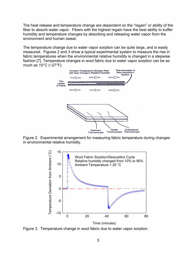
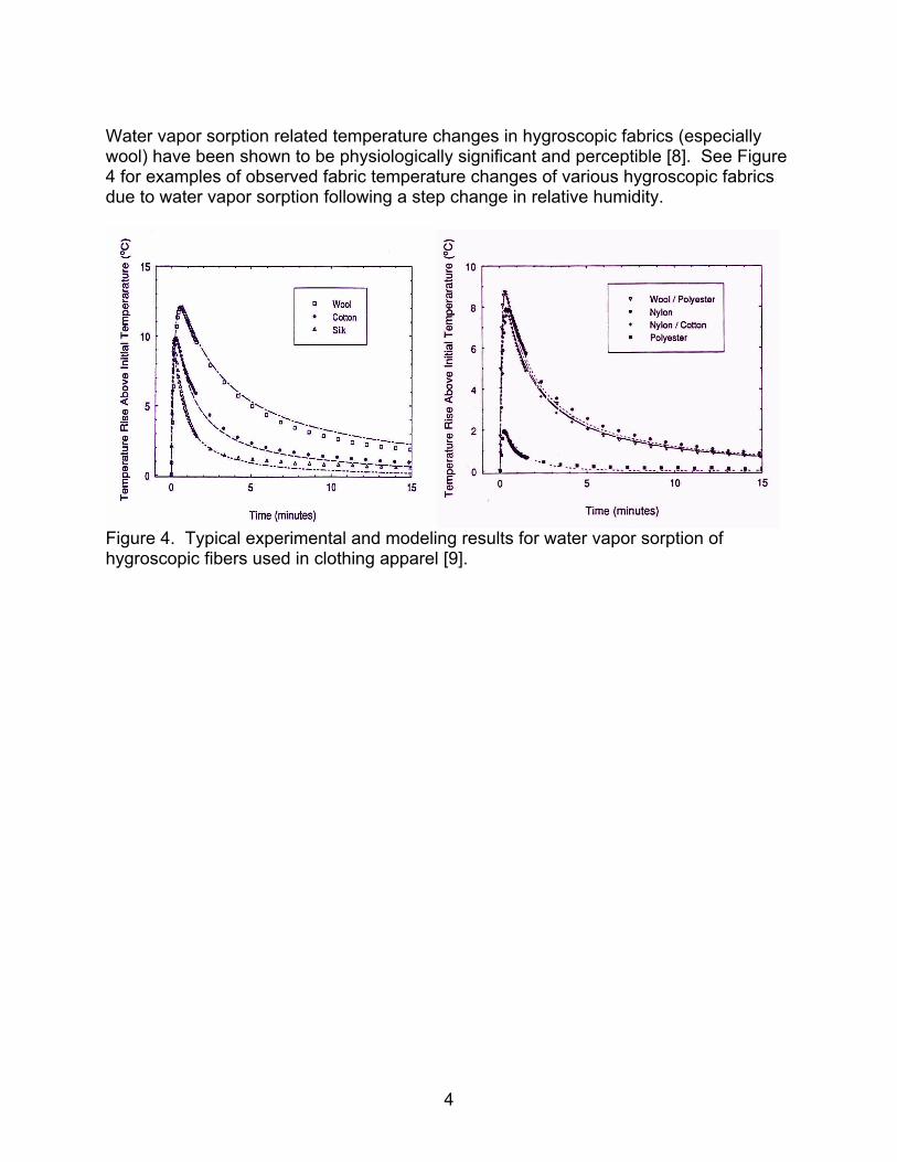
The heat release and temperature change are dependent on the “regain” or ability of the fiber to absorb water vapor. Fibers with the highest regain have the best ability to buffer humidity and temperature changes by absorbing and releasing water vapor from the environment and human sweat. The temperature change due to water vapor sorption can be quite large, and is easily measured. Figures 2 and 3 show a typical experimental system to measure the rise in fabric temperatures when the environmental relative humidity is changed in a stepwise fashion [7]. Temperature changes in wool fabric due to water vapor sorption can be as much as 15°C (~27°F).
Figure 2. Experimental arrangement for measuring fabric temperature during changes in environmental relative humidity.
Figure 3. Temperature change in wool fabric due to water vapor sorption.
-10
-5
0
5
10
15
0 20 40 60 80
Wool Fabric Sorption/Desorption CycleRelative humidity changed from 10% to 90%Ambient Temperature = 20 °C
Time (minutes)
Tem
pera
ture
Dev
iatio
n fro
m A
mbi
ent (
°C)
4
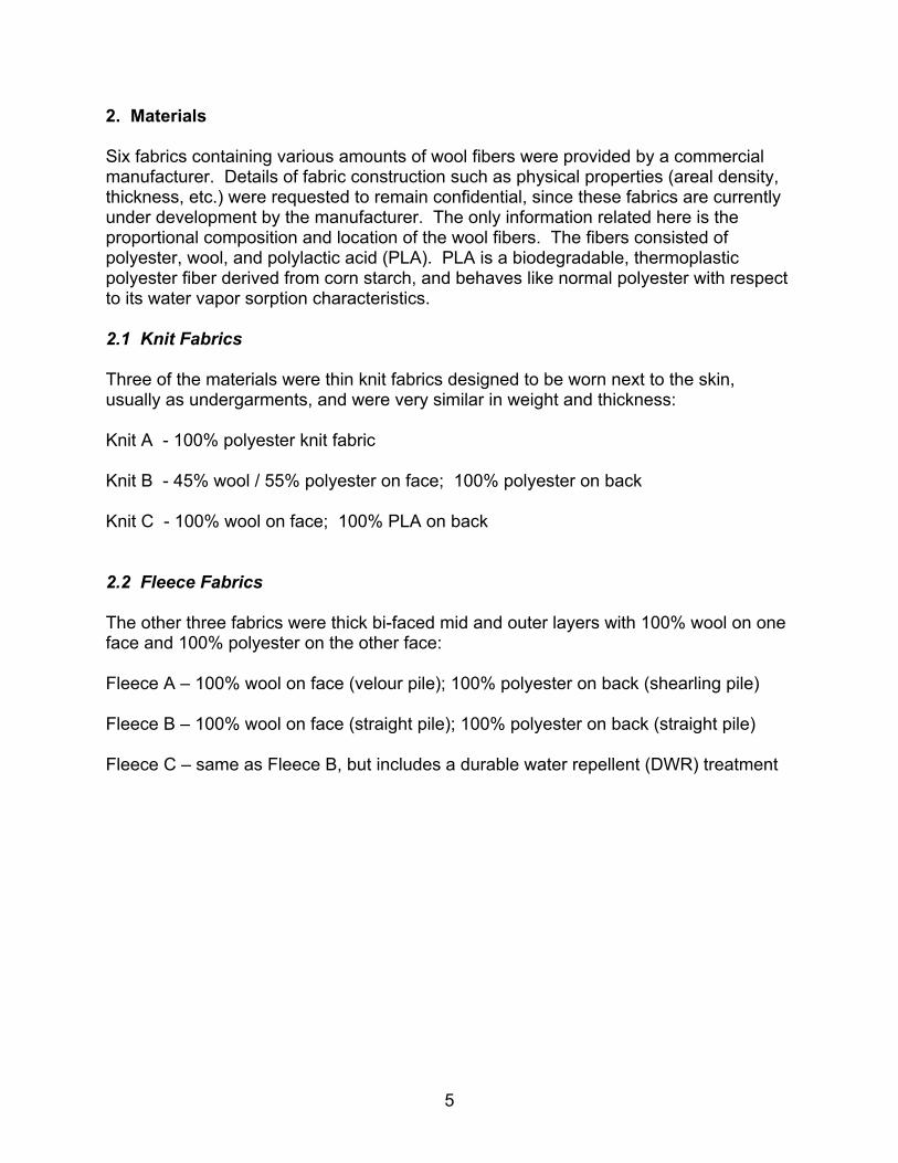
Water vapor sorption related temperature changes in hygroscopic fabrics (especially wool) have been shown to be physiologically significant and perceptible [8]. See Figure 4 for examples of observed fabric temperature changes of various hygroscopic fabrics due to water vapor sorption following a step change in relative humidity.
Figure 4. Typical experimental and modeling results for water vapor sorption of hygroscopic fibers used in clothing apparel [9].
5
2. Materials Six fabrics containing various amounts of wool fibers were provided by a commercial manufacturer. Details of fabric construction such as physical properties (areal density, thickness, etc.) were requested to remain confidential, since these fabrics are currently under development by the manufacturer. The only information related here is the proportional composition and location of the wool fibers. The fibers consisted of polyester, wool, and polylactic acid (PLA). PLA is a biodegradable, thermoplastic polyester fiber derived from corn starch, and behaves like normal polyester with respect to its water vapor sorption characteristics. 2.1 Knit Fabrics Three of the materials were thin knit fabrics designed to be worn next to the skin, usually as undergarments, and were very similar in weight and thickness: Knit A - 100% polyester knit fabric Knit B - 45% wool / 55% polyester on face; 100% polyester on back Knit C - 100% wool on face; 100% PLA on back 2.2 Fleece Fabrics The other three fabrics were thick bi-faced mid and outer layers with 100% wool on one face and 100% polyester on the other face: Fleece A – 100% wool on face (velour pile); 100% polyester on back (shearling pile) Fleece B – 100% wool on face (straight pile); 100% polyester on back (straight pile) Fleece C – same as Fleece B, but includes a durable water repellent (DWR) treatment
6
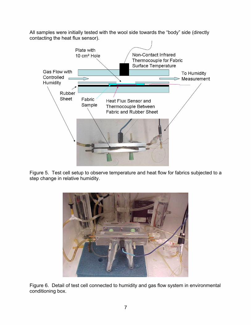
3. Experimental Method Experiments were conducted to examine three main issues: effect of wool content, effect of fabric orientation, and effect of DWR treatment: 1) Effect of Wool Content on the Knit Fabrics – It is assumed that a higher proportion of wool fibers in similar fabrics will result in a higher heat of sorption and a higher heat flux into the skin during water vapor sorption, and higher heat flux out of the skin during vapor desorption. An instrumented water vapor sorption test using a heat flux sensor mounted on a simulated human skin surface was performed to test this hypothesis. 2) Effect of Fabric Orientation on Knit and Fleece Fabrics - The instrumented water vapor sorption test was repeated for the Knit C (Wool/PLA) and Fleece A (Wool/Polyester) fabrics with: the wool face toward the heat flux sensor (body) and the wool face away from the heat flux sensor. Both of these fabrics have 100% wool on one side, and 100% PLA or polyester on the other side. This test was designed to determine whether the orientation of the bi-faced fabric would affect the response measured in the water vapor sorption test. In other words, if the hygroscopic wool side is oriented to the skin, is there more of an effect than if the wool is facing away from the skin? 3) Effect of DWR Treatment on Bi-Faced Fleece Fabrics – DWR treatments are applied to fabrics to increase the liquid water repellency of the surface. If DWR finishes are applied too heavily, it is possible that the fiber surface would be sealed off from interaction with the environment. The instrumented test was repeated again to determine if the DWR treatments on wool/polyester pile fabrics affect the water vapor sorption process. Step changes in relative humidity were used to maximize the thermal effects due to water vapor sorption and desorption. A gas humidifying system that can change relative humidity of the gas flow in a step-wise fashion was used to pass a gas flow over the surface of the fabric sample, shown in Figure 5. A fabric sample was placed on top of the sensor, and humidity-controlled gas flowed through the top portion of the flow cell. The heat flux sensor was oriented so that a heat flow from the environment to the body would show as negative, and a heat flow from the body to the environment would show as positive. Details of the of the test cell connected to the conditioning system are shown in Figure 6; more information on the apparatus is available in Reference 10. A non-contact infrared thermocouple mounted above the sample observed the change in fabric surface temperature. A heat flux meter mounted underneath the sample on a flat rubber sheet, shown in Figure 7, recorded the actual heat flow from the fabric into the sheet. The rubber sheet was meant to simulate human skin thermal properties. A second thermocouple mounted on the rubber sheet near the heat flux sensor recorded the temperature change underneath the fabric. The exposed fabric sample area was 10 cm². All tests were done at a controlled temperature of 30°C (~86°F).
7
All samples were initially tested with the wool side towards the “body” side (directly contacting the heat flux sensor).
Figure 5. Test cell setup to observe temperature and heat flow for fabrics subjected to a step change in relative humidity.
Figure 6. Detail of test cell connected to humidity and gas flow system in environmental conditioning box.
8
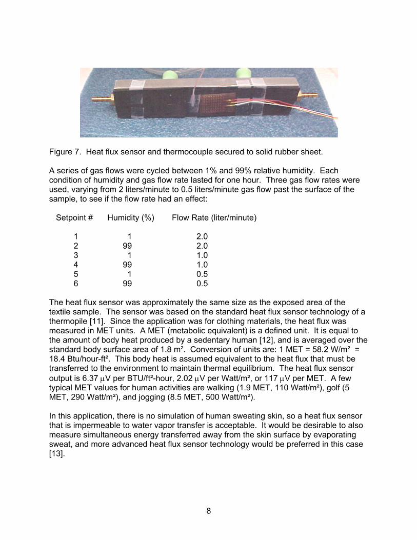
Figure 7. Heat flux sensor and thermocouple secured to solid rubber sheet. A series of gas flows were cycled between 1% and 99% relative humidity. Each condition of humidity and gas flow rate lasted for one hour. Three gas flow rates were used, varying from 2 liters/minute to 0.5 liters/minute gas flow past the surface of the sample, to see if the flow rate had an effect: Setpoint # Humidity (%) Flow Rate (liter/minute) 1 1 2.0 2 99 2.0 3 1 1.0 4 99 1.0 5 1 0.5 6 99 0.5 The heat flux sensor was approximately the same size as the exposed area of the textile sample. The sensor was based on the standard heat flux sensor technology of a thermopile [11]. Since the application was for clothing materials, the heat flux was measured in MET units. A MET (metabolic equivalent) is a defined unit. It is equal to the amount of body heat produced by a sedentary human [12], and is averaged over the standard body surface area of 1.8 m². Conversion of units are: 1 MET = 58.2 W/m² = 18.4 Btu/hour-ft². This body heat is assumed equivalent to the heat flux that must be transferred to the environment to maintain thermal equilibrium. The heat flux sensor output is 6.37 μV per BTU/ft²-hour, 2.02 μV per Watt/m², or 117 μV per MET. A few typical MET values for human activities are walking (1.9 MET, 110 Watt/m²), golf (5 MET, 290 Watt/m²), and jogging (8.5 MET, 500 Watt/m²). In this application, there is no simulation of human sweating skin, so a heat flux sensor that is impermeable to water vapor transfer is acceptable. It would be desirable to also measure simultaneous energy transferred away from the skin surface by evaporating sweat, and more advanced heat flux sensor technology would be preferred in this case [13].
9
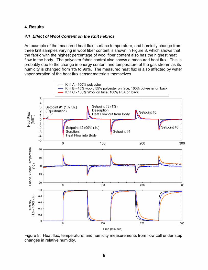
4. Results 4.1 Effect of Wool Content on the Knit Fabrics An example of the measured heat flux, surface temperature, and humidity change from three knit samples varying in wool fiber content is shown in Figure 8, which shows that the fabric with the highest percentage of wool fiber content also has the highest heat flow to the body. The polyester fabric control also shows a measured heat flux. This is probably due to the change in energy content and temperature of the gas stream as its humidity is changed from 1% to 99%. The measured heat flux is also affected by water vapor sorption of the heat flux sensor materials themselves.
0
0.2
0.4
0.6
0.8
1.0
0 100 200 300
Time (minutes)
Hum
idity
(1.0
= 1
00%
r.h.
)
20
25
30
35
40
0 100 200 300Fabr
ic S
urfa
ce T
empe
ratu
re
(°C
)
-5-4-3-2-1012345
0 100 200 300
Knit A - 100% polyesterKnit B - 45% wool / 55% polyester on face, 100% polyester on backKnit C - 100% Wool on face, 100% PLA on back
Setpoint #6
Setpoint #5Setpoint #1 (1% r.h.)(Equilibration)
Setpoint #4
Setpoint #3 (1%)Desorption,Heat Flow out from Body
Setpoint #2 (99% r.h.)Sorption, Heat Flow into Body
Hea
t Flu
x(M
ET)
Figure 8. Heat flux, temperature, and humidity measurements from flow cell under step changes in relative humidity.
10
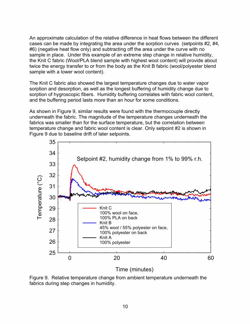
An approximate calculation of the relative difference in heat flows between the different cases can be made by integrating the area under the sorption curves (setpoints #2, #4, #6) (negative heat flow only) and subtracting off the area under the curve with no sample in place. Under this example of an extreme step change in relative humidity, the Knit C fabric (Wool/PLA blend sample with highest wool content) will provide about twice the energy transfer to or from the body as the Knit B fabric (wool/polyester blend sample with a lower wool content). The Knit C fabric also showed the largest temperature changes due to water vapor sorption and desorption, as well as the longest buffering of humidity change due to sorption of hygroscopic fibers. Humidity buffering correlates with fabric wool content, and the buffering period lasts more than an hour for some conditions. As shown in Figure 9, similar results were found with the thermocouple directly underneath the fabric. The magnitude of the temperature changes underneath the fabrics was smaller than for the surface temperature, but the correlation between temperature change and fabric wool content is clear. Only setpoint #2 is shown in Figure 9 due to baseline drift of later setpoints.
25
26
27
28
29
30
31
32
33
34
35
0 20 40 60
Knit C100% wool on face, 100% PLA on backKnit B45% wool / 55% polyester on face, 100% polyester on backKnit A100% polyester
Setpoint #2, humidity change from 1% to 99% r.h.
Time (minutes)
Tem
pera
ture
(°C
)
Figure 9. Relative temperature change from ambient temperature underneath the fabrics during step changes in humidity.
11
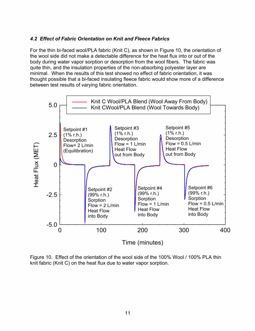
4.2 Effect of Fabric Orientation on Knit and Fleece Fabrics For the thin bi-faced wool/PLA fabric (Knit C), as shown in Figure 10, the orientation of the wool side did not make a detectable difference for the heat flux into or out of the body during water vapor sorption or desorption from the wool fibers. The fabric was quite thin, and the insulation properties of the non-absorbing polyester layer are minimal. When the results of this test showed no effect of fabric orientation, it was thought possible that a bi-faced insulating fleece fabric would show more of a difference between test results of varying fabric orientation.
-5.0
-2.5
0
2.5
5.0
0 100 200 300 400
Knit C Wool/PLA Blend (Wool Away From Body)Knit CWool/PLA Blend (Wool Towards Body)
Setpoint #6 (99% r.h.)SorptionFlow = 0.5 L/min Heat Flow into Body
Setpoint #5 (1% r.h.)DesorptionFlow = 0.5 L/minHeat Flow out from Body
Setpoint #4 (99% r.h.)SorptionFlow = 1 L/min Heat Flow into Body
Setpoint #3 (1% r.h.)DesorptionFlow = 1 L/minHeat Flow out from Body
Setpoint #2 (99% r.h.)SorptionFlow = 2 L/min Heat Flow into Body
Setpoint #1 (1% r.h.)Desorption Flow= 2 L/min(Equilibration)
Time (minutes)
Hea
t Flu
x (M
ET)
Figure 10. Effect of the orientation of the wool side of the 100% Wool / 100% PLA thin knit fabric (Knit C) on the heat flux due to water vapor sorption.
12
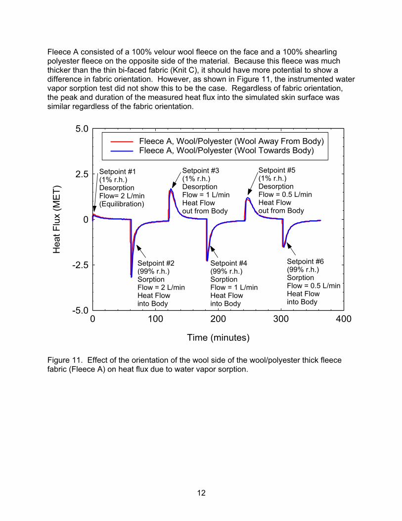
Fleece A consisted of a 100% velour wool fleece on the face and a 100% shearling polyester fleece on the opposite side of the material. Because this fleece was much thicker than the thin bi-faced fabric (Knit C), it should have more potential to show a difference in fabric orientation. However, as shown in Figure 11, the instrumented water vapor sorption test did not show this to be the case. Regardless of fabric orientation, the peak and duration of the measured heat flux into the simulated skin surface was similar regardless of the fabric orientation.
-5.0
-2.5
0
2.5
5.0
0 100 200 300 400
Fleece A, Wool/Polyester (Wool Away From Body)Fleece A, Wool/Polyester (Wool Towards Body)
Setpoint #6 (99% r.h.)SorptionFlow = 0.5 L/min Heat Flow into Body
Setpoint #4 (99% r.h.)SorptionFlow = 1 L/min Heat Flow into Body
Setpoint #2 (99% r.h.)SorptionFlow = 2 L/min Heat Flow into Body
Setpoint #5 (1% r.h.)DesorptionFlow = 0.5 L/minHeat Flow out from Body
Setpoint #3 (1% r.h.)DesorptionFlow = 1 L/minHeat Flow out from Body
Setpoint #1 (1% r.h.)Desorption Flow= 2 L/min(Equilibration)
Time (minutes)
Hea
t Flu
x (M
ET)
Figure 11. Effect of the orientation of the wool side of the wool/polyester thick fleece fabric (Fleece A) on heat flux due to water vapor sorption.
13
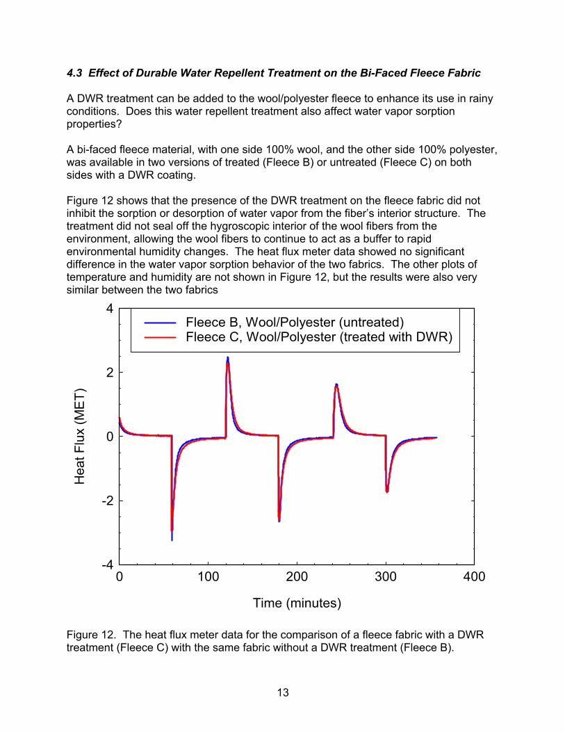
4.3 Effect of Durable Water Repellent Treatment on the Bi-Faced Fleece Fabric A DWR treatment can be added to the wool/polyester fleece to enhance its use in rainy conditions. Does this water repellent treatment also affect water vapor sorption properties? A bi-faced fleece material, with one side 100% wool, and the other side 100% polyester, was available in two versions of treated (Fleece B) or untreated (Fleece C) on both sides with a DWR coating. Figure 12 shows that the presence of the DWR treatment on the fleece fabric did not inhibit the sorption or desorption of water vapor from the fiber’s interior structure. The treatment did not seal off the hygroscopic interior of the wool fibers from the environment, allowing the wool fibers to continue to act as a buffer to rapid environmental humidity changes. The heat flux meter data showed no significant difference in the water vapor sorption behavior of the two fabrics. The other plots of temperature and humidity are not shown in Figure 12, but the results were also very similar between the two fabrics
-4
-2
0
2
4
0 100 200 300 400
Fleece B, Wool/Polyester (untreated)Fleece C, Wool/Polyester (treated with DWR)
Time (minutes)
Hea
t Flu
x (M
ET)
Figure 12. The heat flux meter data for the comparison of a fleece fabric with a DWR treatment (Fleece C) with the same fabric without a DWR treatment (Fleece B).
14
5. Conclusions Standard polyester fleece can be enhanced by adding wool fibers. Wool fibers can be used to increase the thermal regulation and humidity buffering capacity of polyester fleece fabrics. Fine denier wool fibers will also have increased tactile comfort over the larger denier polyester fiber fabrics. Wool fibers in fleece garments have the potential to increase the flame resistance and enhance the flame retardancy of cold-weather military uniforms. DWR treatments can be applied to wool/polyester fleece fabrics so that they do not interfere with the water vapor sorption and thermal regulation properties of wool fibers. For both the thin knit fabrics and the thick fleece fabrics, the orientation of the wool side of the bi-faced fabric towards or away from the skin does not affect the magnitude or duration of the measured heat flux due to water vapor sorption or desorption. Other practical questions remain regarding the incorporation of wool fibers into polyester fiber pile fabrics: • Do wool fibers affect the pilling and durability of polyester fleece fabrics (modern high-
quality polyester fleece is extremely durable and pill-resistant)? • Is the moisture-buffering capability offered by wool fibers in under-garment or fleece
layers enough of a performance advantage to justify the added expense? • Are enzyme-scoured wool fibers sufficiently flame-retardant to be used in thermally-
protective military outerwear, or are more traditional Wool/Nomex blends necessary for this application?
This document reports research undertaken at the U.S. Army Natick Soldier Research, Development and Engineering Center, Natick, MA, and has been assigned No. NATICK/TR-08/013 in a series of reports approved for publication.
15
6. References 1. Hoschke, B., “Flame-Resistant Wool/Nomex Blends,” Textile Research Journal 44 (12), pp. 956-958, 1974. 2. Cardamone, J., “Activated Peroxide for Enzymatic Control of Wool Shrinkage Part II: Wool and Other Fiber-type Fabrics,” Textile Research Journal 76 (2), pp. 109-115, 2006. 3. Cardamone, J., Kanchagar, A., “Method of inhibiting the burning of natural fibers, synthetic fibers, or mixtures thereof, or fabric or yarn composed of natural fibers, synthetic fibers, or mixtures thereof, and products produced by such methods,” US Patent 7,264,637, 2007. 4. Jones, L, Rivett, D., Tucker, D., “Wool and Related Mammalian Fibers,” in Handbook of Fiber Chemistry, 2nd Edition, edited by Lewin, M., Pearce, E., Marcel Dekker, New York, pp. 357-359, 1989. 5. Thompson, B., “Experiments Made to Determine the Positive and Relative Quantities of Moisture Absorbed from the Atmosphere by Various Substances, under Similar Circumstances,” Philosophical Transactions of the Royal Society of London 77, 1787, pp. 240-245, 1787. 6. Martin, T., “The Experimental Researches of Benjamin Thompson, Count Rumford,” Bulletin of the British Society for the History of Science, 1 (6), pp. 144-158, 1951. 7. Gibson, P., Charmchi, M., “The Use of Volume-Averaging Techniques to Predict Temperature Transients Due to Water-Vapor Sorption in Hygroscopic Porous Polymer Materials,” Journal of Applied Polymer Science 64 (3), pp. 493-505, 1997. 8. Stuart, I., Schneider, A., Turner, T., “Perception of the Heat of Sorption of Wool,” Textile Research Journal 59 (6), pp. 324-329, 1989. 9. Gibson, P., "Multiphase Heat and Mass Transfer through Hygroscopic Porous Media with Applications to Clothing Materials," U.S. Army Natick Research, Development, and Engineering Center Technical Report, Natick/TR-97/005, December, 1996, available online at: http://handle.dtic.mil/100.2/ADA319094. 10. Gibson, P., "Water Vapor Transport and Gas Flow Properties of Textiles, Polymer Membranes, and Fabric Laminates," Journal of Coated Fabrics 28, p. 300-327, 1999. 11. Childs, P., Greenwood, J., Long, C., “Heat flux measurement techniques,” Journal of the Proceedings of the Institution of Mechanical Engineers, Part C: Journal of Mechanical Engineering Science 213 (7), pp. 655-677, 1999. 12. Gagge, A., Burton, A., Bazett, H., “A practical system of units for the description of the heat exchange of man with his environment,” Science 94 (2445), pp. 428-430, 1941. 13. Dupont, D., Godts, P., Leclercq, “Design of Textile Heat Flowmeter Combining Evaporation Phenomena,” Textile Research Journal 76 (10), pp. 772-776, 2006.