Embed Size (px)
Citation preview
International Research Journal of Engineering and Technology (IRJET) e-ISSN: 2395 -0056
Volume: 04 Issue: 06 | June -2017 www.irjet.net p-ISSN: 2395-0072
© 2017, IRJET | Impact Factor value: 5.181 | ISO 9001:2008 Certified Journal | Page 2312
Effect of various parameters on double lap bolted GFRP-to-steel joint by experimentally and numerically
Amol N. Kadam1, S. M. Ingale2
1Research Scholar, Dept. of Mechanical Engineering, SGI Atrigre, 416118, India,
2Associate Professor, Dept. of Mechanical Engineering, SGI Atrigre, 416118, India. -----------------------------------------------------------------------------***----------------------------------------------------------------------------Abstract- In structural applications such as in aircraft, space craft and in civil engineering structures the components are often fasten to the structural members by threaded fasteners to maintain integrity in fastened structure due to their high reliability, strong load bearing capacity, easier to assemble and disassemble, more tolerant to environmental damages and helpful in preventing interlamination. The bolted joints are carefully designed due to the stress concentration at the surrounding of the hole. It is well known that stress concentrations near the fastener holes could initiate delamination, which severely reduces the strength of the structure. The bolted joint strength is also affect by parameters such as joint configuration, joint geometry, loading conditions, etc. The present work is focused on analyzing effect of various parameters such as washer outer diameter sizes, preload, and edge to hole diameter ratio on the strength of double lap bolted joint structure subjected to tensile loading by using experimental and numerically. The numerical results were found in good agreement with the experimental results. Keywords: bolted joint, double lap, GFRP, strength Nomenclature: L Length of plate W Width of Plates D Minimum hole diameter Plate thickness of GFRP plate Plate thickness of steel plate E Edge distance p centre to centre distance between two bolts T Tightening torque Washer outer diameter size Preload FEA Finite Element Analysis FEM Finite Element Method 1. INTRODUCTION In general, built-up structures are the combinations of different types of joining. The method of assembly is important consideration in design of built-up structures. In structural applications such as in aircraft, space craft and in civil engineering structures the components are often fasten to the structural members by threaded fasteners to maintain integrity in fastened structure. In general,
increase in bolt-fastening forces lead increase in joint strength compared to the other joints because it is relatively more reliable to transfer higher loads, easier to assemble and disassemble, more tolerant to environmental damages and helpful in preventing interlamination. The bolted joints are carefully designed due to the stress concentration at the surrounding of the hole. It is well known that stress concentrations near the fastener holes could initiate delamination, which severely reduces the strength of the structure. The bolted joint strength is also affect by parameters such as joint configuration, joint geometry, loading conditions, fastening parameters, and material parameters. The main objective of this paper is to study the effects of washer outer diameter size, preload, and edge to hole diameter ratio on strength of double lap single bolted joint using experimentally and finite element analysis. 2. LITERATURE REVIEW
Tajeuna et. al.[1] studied the effect of geometrical parameters of Al-to-steel bolted connections to predict the optimal geometric configuration foe single-lap and double-lap bolted connections by experimentally and numerically. P.A. Sharos et. al. [2] was predicts the strength of multi-bolted composite joint at various loading rates by analytically using damage approximation function. V.P. Lawlor et. al. [3] was studied the effect of variable clearance in multi-bolt, double lap, composite joint on load distribution, quasi-static strength, fatigue life and failure modes by experimentally. U.A. Khashaba et. al. [4] was studied the effect washer size and tightening torque on the performance of bolted joints in [0/±45/90] glass fiber reinforced epoxy (GFRE) composites and determined the mechanical properties (tensile, compressive, and in-plan shear) of GFRE laminates by experimentally and theoretically. M.P.Cavatorta et. al. [5] described a finite element simulation and experimental validation of a composite bolted joint loaded in bending and torsion. Ali Najafi et. al. [6] studied the failure behavior of bolted joints including failure mode, failure load and joint stiffness through finite element simulation embedded in progressive failure analysis (PFA). T.N.Chakherlou et. al. [7] studied the effect of the clamping force variation in interference fitted double shear lap bolted joints of aluminum 2024-T3 under static and cyclic loads by experimentally and also FE analysis was performed to compare with experiments of

International Research Journal of Engineering and Technology (IRJET) e-ISSN: 2395 -0056
Volume: 04 Issue: 06 | June -2017 www.irjet.net p-ISSN: 2395-0072
© 2017, IRJET | Impact Factor value: 5.181 | ISO 9001:2008 Certified Journal | Page 2313
the static loading. Kunliang Liu et. al. [8] studied the effects of pre-tightening force and connection mode on the strength and progressive damage of composite laminates with bolted joints by FE analysis and compares their results with analytical results. Jong-Hwa Yun et. al. [9] was evaluated the new method for improving the strength of multi-bolted joints by considering the effect of hole clearance by experimentally and FEA. Faruk Sen et. al. [10] performed an experimental failure analysis to determine the failure behavior of bolted composite joint under various preload moments, two different geometrical parameters (edge- to-hole dia. ratio (E/D) and plate width-to-hole dia. Ratio (W/D)) and ply orientations. Fengrui Liu et. al. [11] was developed an analytical tri-linear joint stiffness model for load transfer analysis in highly torque multi-bolt composite joints with clearance. 3. EXPERIMENTAL ANALYSES The experimental analysis is carried out to measure strength of double lap single bolted joint structures by using computerised universal testing machine. The schematic representation of experimental setup is shown in fig.1.Experimental testing specimen containing two steel plates and one GFRP plate is shown in fig. 2. The size of plates, steel plate is 192mm X 40mm X 5mm and GFRP plate is 192mm X 40mm X 2mm. To measure displacement occurred in the joint during the experiment the gauge length is marked on the GFRP plate.
Fig. 1 Experimental Setup
Fig. 2 Double lap Single bolted joint
A. Steps in Experimental Analysis 1. Take composite plate specimen and the gauge length is
marked on that to measure the total deflection occurred after experiment.
2. Then the composite plate fastened with steel plates with help of bolt to form double lap bolted joint.
3. The tightening torque is applied on bolt with help of torque wrench to get required preload.
4. The bolted joint was clamped between the two jaws of universal testing machine.
5. Suitable connections were made to get required readings through computer.
6. The control panel of universal testing machine has two operating valves at both ends to maintain required oil pressure.
7. The tensile load was applied on the joint and maximum load, total deflection and Ultimate strength was measured.
8. Experiment setup was taken to the initial condition (i.e. zero load condition).
9. The above procedure was repeated to calculate the strength of the double lap single bolted structure by varying following parameters such as, a) Washer outer dia. size [20mm, 23mm and 30mm]
b) Preload [25KN, 30KN and 35 KN] c) Edge to hole diameter ratio (E/D) [3, 4 and 5] 4. FINITE ELEMENT ANYLSIS
A. Configuration of test specimen Similar to the experimental specimen, the FE model has six basic components: two steel plates, GFRP plate, Washer, Bolt and Nut as shown in fig.3. The solid model of specimen is prepared by using Creo Parametric 2.0 software and the model is saved in IGS file format. The solid model is imported into ANSYS Workbench 16.0 for FEA.
Fig. 3 Double Lap Single Bolted Joint
B. Material Property
The1045 Steel for plate 1 and plate 3 and GFRP (Woven E-Glass epoxy) for plate 2 and; Medium carbon alloy steel for Nut and Bolt and alloy steel for Washer is used. The material property of fastened plates is shown in Table 1and Table 2.
Double lap
bolted joint
testing
specimen with
gauge length
mark on
GFRP plate
UTM
Control
System
Computer for
Recording Data
International Research Journal of Engineering and Technology (IRJET) e-ISSN: 2395 -0056
Volume: 04 Issue: 06 | June -2017 www.irjet.net p-ISSN: 2395-0072
© 2017, IRJET | Impact Factor value: 5.181 | ISO 9001:2008 Certified Journal | Page 2314
Density 7810 Kg/ Modulus Of Elasticity 201GPa
Poisson’s Ratio 0.3 Yield Strength 507MPa
Tangent Modulus 3350MPa Tensile Ultimate Strength 250MPa Tensile Ultimate Strength 460MPa
Table 1 Material Property of 1045 steel
Elastic properties
Young’s modulus GPa
Poisson’s ratio (µ)
Shear modulus (G)
GPa = 25GPa = 0.2
4 GPa = 25GPa =0.2 = 0.6E11GPa =0.2
Table 2 Material property of GFRP
C. Contact Conditions
There are seven contact interactions are established for all contact surfaces in the finite element model are shown in table 3.
Sr. No Contact Target Type of
Interaction 1 Plate-2 Plate-1 Frictional 2 Plate-2 Plate-3 Frictional 3 Bolt Nut Bonded 4 Washer Plate-3 Frictional
5 All plate
holes Bolt shank Frictional
6 Bolt Washer Frictional 7 Nut Plate-1 Frictional
Table 3 Contact conditions
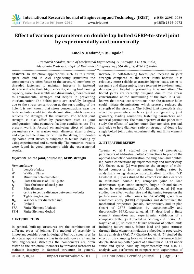
D. Meshing All components of bolted structure are meshed by using Hex Dominant method with Quad/ tri mesh type having mesh size 2mm with fine relevance and span angle centre. There are total 83771 nodes and 15515 elements are formed on meshing. E. Boundary condition All degrees of freedom of all nodes and elements of outer left side surface of plate-1 and plate-3 is fixed support as shown in Fig. 4. F. Loading Conditions From experimental test the value of peak load is get and that amount of load is applied to one side of GFRP plate which is shown in fig. 4. When bolt is tightening by tightening torque, all the washer face of bolt head and nut
i.e. contact face transmit clamping force (Fc) to face of washer and fastened plate i.e. target face respectively which help to clamp fastened plates together as shown in Fig. 4. The contact faces apply uniform distributed load on the target faces. The applied clamping forces are equal in magnitude but opposite in direction along axial direction of bolt shank. Also the preload force (Fp) is applied on the cylindrical surface of the bolt shank along the axial direction which is equal in magnitude but opposite in direction of each other as shown in Fig.4.
Clamping Force ( )
Bolt- Pretension = Preload ( ) Fig. 4 Fixed support and forces acting on bolted joint in FEA 5. RESULTS AND DISCUSSION The results obtained from the experiment and finite element analysis of double lap single bolted joint for different parameters are discussed below, A. Effect of Washer outer diameter size on bolted joint
strength
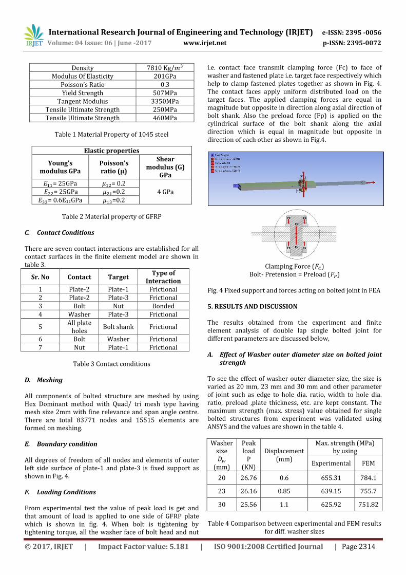
To see the effect of washer outer diameter size, the size is varied as 20 mm, 23 mm and 30 mm and other parameter of joint such as edge to hole dia. ratio, width to hole dia. ratio, preload ,plate thickness, etc. are kept constant. The maximum strength (max. stress) value obtained for single bolted structures from experiment was validated using ANSYS and the values are shown in the table 4.
Washer size
(mm)
Peak load
P (KN)
Displacement (mm)
Max. strength (MPa) by using
Experimental FEM
20 26.76 0.6 655.31 784.1
23 26.16 0.85 639.15 755.7
30 25.56 1.1 625.92 751.82
Table 4 Comparison between experimental and FEM results
for diff. washer sizes
International Research Journal of Engineering and Technology (IRJET) e-ISSN: 2395 -0056
Volume: 04 Issue: 06 | June -2017 www.irjet.net p-ISSN: 2395-0072
© 2017, IRJET | Impact Factor value: 5.181 | ISO 9001:2008 Certified Journal | Page 2315
Fig. 5 Comparative graph of strength analysis of different washer outer diameter sizes
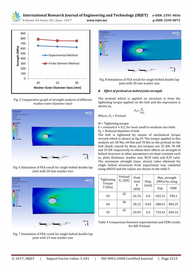
Fig. 6 Simulation of FEA result for single bolted double lap joint with 20 mm washer size
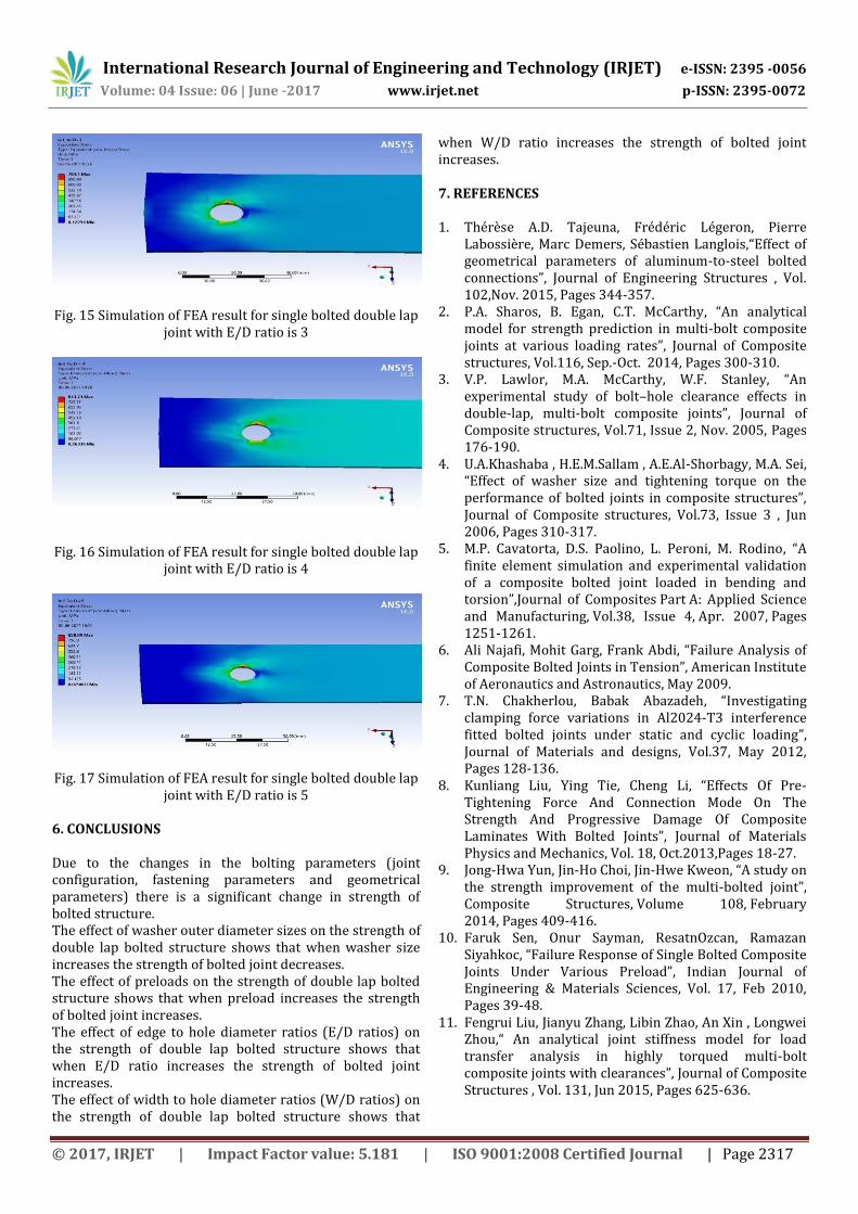
Fig. 7 Simulation of FEA result for single bolted double lap joint with 23 mm washer size
Fig. 8 Simulation of FEA result for single bolted double lap joint with 30 mm washer size
B. Effect of preload on bolted joint strength The preload which is applied on structure is from the tightening torque applied on the bolt and the expression is shown as,
=
Where, = Preload M = Tightening torque k = constant k 0.2, for most small to medium size bolts = Nominal diameter of bolt The bolt is tightened by means of mechanical torque wrench which is shown in fig.10. The torque applied in this analysis are 50 Nm, 60 Nm and 70 Nm so the preload on the bolt shank caused by these pre-torques are 25 KN, 30 KN and 35 KN respectively to obtain their effects on strength of bolted structure at other parameters are kept constant such as, plate thickness, washer size, W/D ratio and E/D ratio. The maximum strength (max. stress) value obtained for single bolted structures from experiment was validated using ANSYS and the values are shown in the table 5.
Tightening Torque T (Nm)
Preload (KN)
Peak load
P (KN)
Disp. (mm)
Max. strength (MPa) by using
Exp. FEM
50 25
26.76 0.6 655.31 784.1
60 30
28.12 0.65 688.61 803.25
70 35
29.95 0.5 733.43 849.16
Table 4 Comparison between experimental and FEM results
for diff. Preload
0
100
200
300
400
500
600
700
800
900
20 23 30
Stre
ngt
h (
MP
a)
Washer Outer Diameter Sizes (mm)
Experimental Method
Finite Element Method

International Research Journal of Engineering and Technology (IRJET) e-ISSN: 2395 -0056
Volume: 04 Issue: 06 | June -2017 www.irjet.net p-ISSN: 2395-0072
© 2017, IRJET | Impact Factor value: 5.181 | ISO 9001:2008 Certified Journal | Page 2316
Fig. 9 Comparative graph of strength analysis of different preload
Fig. 10 Torque wrench
Fig. 11 Simulation of FEA result for single bolted double lap joint with preload 25 KN
Fig. 12 Simulation of FEA result for single bolted double lap joint with preload 30 KN
Fig. 13 Simulation of FEA result for single bolted double lap joint with preload 35 KN
C. Effect of edge to hole diameter (E/D) ratio on bolted
joint strength The three different levels of E/D ratio were chosen as shown in table 5 to find their effect on the strength of joint.
E/D
Peak load
P (KN)
Displacement (mm)
Max. strength (MPa) by using
Experimental FEM
3 26.76 0.6 655.31 784.1
4 28.00 1 685.67 813.75
5 28.78 1.5 704.29 828.89
Table 5 Comparison between experimental and FEM results
for diff. E/D ratio
Fig. 14 Comparative graph of strength analysis of different E/D ratio
The results show that the increasing E/D ratio affects the strength bolted joint. The strength increases with the increase in E/D ratio as shown in fig.14.
0
200
400
600
800
1000
25 30 35
Stre
ngt
h (
MP
a)
Preload (KN)
Experimental Method
Finite Element Method
0
200
400
600
800
1000
3 4 5
Stre
ngt
h (
MP
a)
E/D ratio
Experimental Method
Finite Element Method
International Research Journal of Engineering and Technology (IRJET) e-ISSN: 2395 -0056
Volume: 04 Issue: 06 | June -2017 www.irjet.net p-ISSN: 2395-0072
© 2017, IRJET | Impact Factor value: 5.181 | ISO 9001:2008 Certified Journal | Page 2317
Fig. 15 Simulation of FEA result for single bolted double lap joint with E/D ratio is 3
Fig. 16 Simulation of FEA result for single bolted double lap joint with E/D ratio is 4
Fig. 17 Simulation of FEA result for single bolted double lap joint with E/D ratio is 5
6. CONCLUSIONS Due to the changes in the bolting parameters (joint configuration, fastening parameters and geometrical parameters) there is a significant change in strength of bolted structure. The effect of washer outer diameter sizes on the strength of double lap bolted structure shows that when washer size increases the strength of bolted joint decreases. The effect of preloads on the strength of double lap bolted structure shows that when preload increases the strength of bolted joint increases. The effect of edge to hole diameter ratios (E/D ratios) on the strength of double lap bolted structure shows that when E/D ratio increases the strength of bolted joint increases. The effect of width to hole diameter ratios (W/D ratios) on the strength of double lap bolted structure shows that
when W/D ratio increases the strength of bolted joint increases. 7. REFERENCES
1. Thérèse A.D. Tajeuna, Frédéric Légeron, Pierre
Labossière, Marc Demers, Sébastien Langlois,“Effect of geometrical parameters of aluminum-to-steel bolted connections”, Journal of Engineering Structures , Vol. 102,Nov. 2015, Pages 344-357.
2. P.A. Sharos, B. Egan, C.T. McCarthy, “An analytical model for strength prediction in multi-bolt composite joints at various loading rates”, Journal of Composite structures, Vol.116, Sep.-Oct. 2014, Pages 300-310.
3. V.P. Lawlor, M.A. McCarthy, W.F. Stanley, “An experimental study of bolt–hole clearance effects in double-lap, multi-bolt composite joints”, Journal of Composite structures, Vol.71, Issue 2, Nov. 2005, Pages 176-190.
4. U.A.Khashaba , H.E.M.Sallam , A.E.Al-Shorbagy, M.A. Sei, “Effect of washer size and tightening torque on the performance of bolted joints in composite structures”, Journal of Composite structures, Vol.73, Issue 3 , Jun 2006, Pages 310-317.
5. M.P. Cavatorta, D.S. Paolino, L. Peroni, M. Rodino, “A finite element simulation and experimental validation of a composite bolted joint loaded in bending and torsion”,Journal of Composites Part A: Applied Science and Manufacturing, Vol.38, Issue 4, Apr. 2007, Pages 1251-1261.
6. Ali Najafi, Mohit Garg, Frank Abdi, “Failure Analysis of Composite Bolted Joints in Tension”, American Institute of Aeronautics and Astronautics, May 2009.
7. T.N. Chakherlou, Babak Abazadeh, “Investigating clamping force variations in Al2024-T3 interference fitted bolted joints under static and cyclic loading”, Journal of Materials and designs, Vol.37, May 2012, Pages 128-136.
8. Kunliang Liu, Ying Tie, Cheng Li, “Effects Of Pre-Tightening Force And Connection Mode On The Strength And Progressive Damage Of Composite Laminates With Bolted Joints”, Journal of Materials Physics and Mechanics, Vol. 18, Oct.2013,Pages 18-27.
9. Jong-Hwa Yun, Jin-Ho Choi, Jin-Hwe Kweon, “A study on the strength improvement of the multi-bolted joint”, Composite Structures, Volume 108, February 2014, Pages 409-416.
10. Faruk Sen, Onur Sayman, ResatnOzcan, Ramazan Siyahkoc, “Failure Response of Single Bolted Composite Joints Under Various Preload”, Indian Journal of Engineering & Materials Sciences, Vol. 17, Feb 2010, Pages 39-48.
11. Fengrui Liu, Jianyu Zhang, Libin Zhao, An Xin , Longwei Zhou,“ An analytical joint stiffness model for load transfer analysis in highly torqued multi-bolt composite joints with clearances”, Journal of Composite Structures , Vol. 131, Jun 2015, Pages 625-636.


![TOOL WEAR PREDICTION IN DRILLING OF GFRP LAMINATES …that the Strength and modulus of the composites increases with decreasing temperature. Palanikumar et al. [ 26] studies on machining](https://img.pdfslide.us/doc/110x75/5feef9b56d0bdf20a30c4155/tool-wear-prediction-in-drilling-of-gfrp-laminates-that-the-strength-and-modulus.jpg)


![GFRP [Hand lay up]](https://img.pdfslide.us/doc/110x75/557cb1dcd8b42abf328b4c0e/gfrp-hand-lay-up.jpg)


![GFRP [Resin Infusion]](https://img.pdfslide.us/doc/110x75/546e67d4af795971298b5642/gfrp-resin-infusion.jpg)