Embed Size (px)
Citation preview
JOURNAL OF ENGINEERING AND APPLIED SCIENCE, VOL. 67, NO. 6, DEC. 2020, PP. 1363-1380
FACULTY OF ENGINEERING, CAIRO UNIVERSITY
EFFECT OF STRUCTURE LATERAL SYSTEM AND IRREGULARITY ON
THE FUNDAMENTAL TIME PERIOD OF STEEL STRUCTURE
M. O. ABOELMAGED1, N. Z. AHMED2, M. N. ABDELMOOTY3
AND W. A. ATTIA4
ABSTRACT
The time period of structures has a significant effect on seismic forces
calculations. However, most of the design code use an approximate empirical formula
that depends mainly on building height, for time period estimation. The aim of this study
is to investigate the effect of lateral load resisting systems and irregularities of building
configuration on the fundamental period of vibration for steel structures. For this
purpose, steel buildings with different lateral systems and irregularities were selected.
36-Moment Resisting Frames (MRFs), 108-Concentric Braced Frames (CBFs) and 68-
Eccentric Braced Frames (EBFs) were studied using ETABS software. Three heights
were considered; 5, 8, and 12 story and three types of irregularity were investigated;
vertical, horizontal and combined irregularities. After full analysis and optimum design
for buildings, the results of the fundamental periods of vibration of this study were
compared with the time period recommended by different international design codes
and standards. The comparison showed that the lateral system and building irregularity
have a significant effect on the fundamental period of vibration for the buildings with
the same height. It is recommended that the code equation for irregular steel buildings
be investigated further.
KEYWORDS: Fundamental time period, Irregularity; EBF, CBF, and MRF, Modal
analysis, Lateral system.
1. INTRODUCTION
In design codes, calculation of the seismic loads requires the estimation of the
fundamental period of the structure. There are various methods that can be used to
estimate the fundamental period. The most accurate way of determining the natural
1 Ph.D. Candidate, Structural Engineering Department, Faculty of Engineering, Cairo University, Egypt
[email protected] 2 Assistant Professor, Structural Engineering Department, Faculty of Engineering, Beni Suef University, Egypt.
3 Professor, Structural Engineering Department, Faculty of Engineering, The American University in Cairo,
Egypt. 4 Professor, Structural Engineering Department, Faculty of Engineering, Cairo University, Egypt.
M. O. ABOELMAGED ET AL
1364
period is to perform an eigenvalue analysis. However, design codes recommend the use
of empirical formulas to estimate the time period. Time period expressions were derived
or verified from time periods measured during earthquakes [1].
Any empirical formula should be based on the periods of buildings measured
from their motions recorded during earthquakes and the structures should be tested by
strongly shaking and no significant deformation recorded in the inelastic range. Thus,
the measured time period should reflect the undamaged stage of the building [2].
Furthermore, most of the design codes recommend lower bound expressions for the time
period. These expressions are usually based on the geometrical properties such as height
and width and can be very useful in the preliminary design stage before the member
sizes are determined. However, these design codes do not consider building irregularity
and the variation in structural systems into consideration. In Euro Code 8 [ 3], for
buildings with heights of up to 40 m, the value of fundamental period T in seconds may
be approximated by as shown in Eq. (1).
𝑇 = 𝐶𝑡 . 𝐻3/4
(1)
Where Ct is a factor depending on the lateral system and it is taken as 0.085 for
Moment Resisting Frames (MRF) and 0.075 for Eccentric Braced Frames (EBF) and
0.05 for all other systems. H is the height of the building, in meter, measured from the
top of the foundation. Egyptian Code for loads [ 4] uses the same approximate
fundamental period (T) recommended by Euro Code 8, but the Egyptian Code for loads
also proposes Eq. (2) to estimate the time period based on Rayleigh formula.
𝑇 = 2𝜋√∑ 𝑊𝑖𝑛𝑖=1 𝑈𝑖
2/𝑔∑ 𝐹𝑖𝑛𝑖=1 𝑈𝑖
(2)
Where Wi is the portion of the total weight of the structure assigned to level i, Fi
is the lateral force at level i, Ui is the deflection at level i relative to the base due to
lateral forces, g is acceleration due to gravity, and n is the total number of stories in the
building. The American Society of Civil Engineers [ 5] suggests the approximate
fundamental period (T), in seconds, as given by Eq. (3).
𝑇 = 𝐶𝑡𝐻𝑥
(3)
Where x depends on the lateral system and Ct = 0.0724, x = 0.8 for MRFs and Ct
= 0.0731, x = 0.75 for EBFs. The Uniform Building Code [6] adopted a similar equation
EFFECT OF STRUCTURE LATERAL SYSTEM AND IRREGULARITY ON ….
1365
to that used in Euro Code 8 but with Ct 0.0853 for MRF and 0.0731 for EBF and 0.0488
for all other systems.
The investigation of the effect of structural system on the time period has been
the subject of much previous research work. The fundamental period of steel moment-
resisting frames, as well as braced steel frames, has been studied. The influence of the
plan and bay dimensions, normalized stiffness and height of stories and various cross-
sections as columns and beams on the fundamental natural frequency has been studied
and, it is found that the fundamental natural frequency decreases with the increase in
height and normalized stiffness of the building irrespective of the building's plan
dimensions [7]. The structural performance and arrangement of bracing configurations
under earthquake ground motions have been investigated [8-11]. The behaviour of
vertically irregular moment resisting building frames have been studied and the
reliability of the irregularity criteria provided by different codes [14].
In the review of the current researches and the empirical code equations, it
became necessary to develop a better understanding of the response of steel structures
with different systems during earthquakes and the effect of their behaviour on the time
period of structures. The main objectives of this research are thus to:
- Study the effect of building structural systems on the time period
- Highlight the importance of the variations of horizontal and vertical irregularities of
the time period
1.1 Code Provisions
The fundamental period of vibration for steel structures must be determined
during the design stage in order to calculate the value of earthquake base shear.
According to the Egyptian code for loads [4], the empirical formula to calculate
the fundamental period for moment resistant space frames is the same as Eq. (1). The
formula considers only the building height. The above formula is applied to steel MRFs
with height 15 m and 3×5 bays width. Furthermore, the optimized design was performed
for the building and the time period results are displayed in Table 1 for the Code
equation, modal analyses, and Rayleigh formula.
M. O. ABOELMAGED ET AL
1366
Table 1. Time period comparison.
Building type ECP 201
2012, Eq. (1)
Rayleigh
Eq., (2) TModal
MRF1-5-3bay 0.648 1.554 1.551
Table 1 shows a significant variation between the values obtained from the code
empirical formula and other results. This variation is due to nonstructural elements such
as walls, which were not considered in the analysis model. In this paper using the
Rayleigh formula Eq. (2) will be considered as the reference to compare the model result
with the code equation to overcome the gap between the empirical code formula and the
analysis result.
2. METHODOLOGY
2.1 Loads
The structures considered in the research are designed according to the Egyptian
Code for Loads and Forces on Structures [4], Egyptian Code of Practice for Steel
Construction and Bridges allowable stress design [12], and American Institute of Steel
Construction [13]. Seismic design is based on the equivalent lateral force procedure of
ECP 201. Table 2 shows the design parameters and loads.
Table 2. Design parameters and loads.
Importance Factor 1
Soil class C
Response spectrum type 1
)2/mNk( live load 3
Dead load 100 mm concrete deck
)2/mNkWall load ( 3
)2/mNkceiling load ( andDucts 1.5
Wind speed (m/s) 42
Steel members are designed using ST37 with 240 N/mm2 minimum yield stress
and 360 N/mm2 tensile strength. European steel catalogue and some built-up sections
are used in the design. A rigid diaphragm is assumed at each floor. ETABS software is
used to perform analysis and design, with many iterations to reach the optimum design.
EFFECT OF STRUCTURE LATERAL SYSTEM AND IRREGULARITY ON ….
1367
2.2 Model Geometry
All considered structure frames are modelled in 3 heights 5, 8 and 12 stories, with
typical story height of 3m. The model consists of 5 bays in the x-direction and 3, 6 and
8 bays in the y-direction with 6 m span of the bay. The bay is divided by secondary
beams at 2 m in the y-direction. Three types of irregularity according to the Egyptian
Code for Loads [ 4] are defined. Vertical, horizontal and combined irregularity are
achieved in this research by removing bays from the horizontal and vertical projection
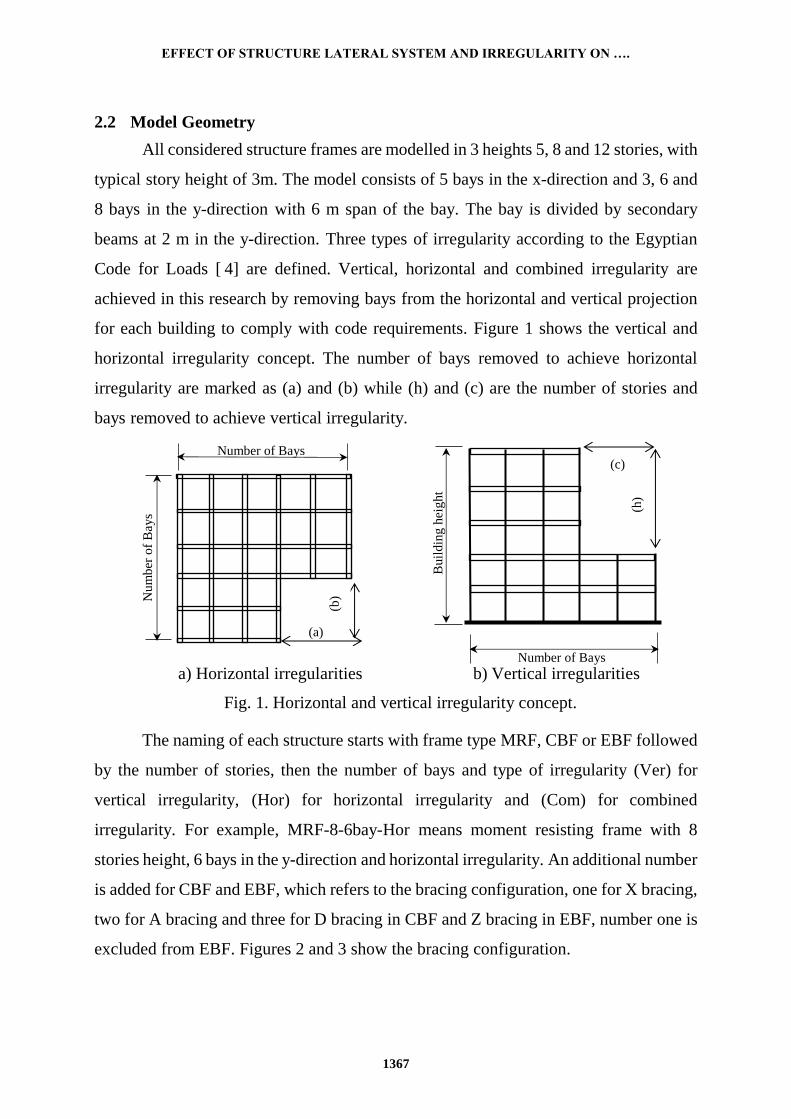
for each building to comply with code requirements. Figure 1 shows the vertical and
horizontal irregularity concept. The number of bays removed to achieve horizontal
irregularity are marked as (a) and (b) while (h) and (c) are the number of stories and
bays removed to achieve vertical irregularity.
The naming of each structure starts with frame type MRF, CBF or EBF followed
by the number of stories, then the number of bays and type of irregularity (Ver) for
vertical irregularity, (Hor) for horizontal irregularity and (Com) for combined
irregularity. For example, MRF-8-6bay-Hor means moment resisting frame with 8
stories height, 6 bays in the y-direction and horizontal irregularity. An additional number
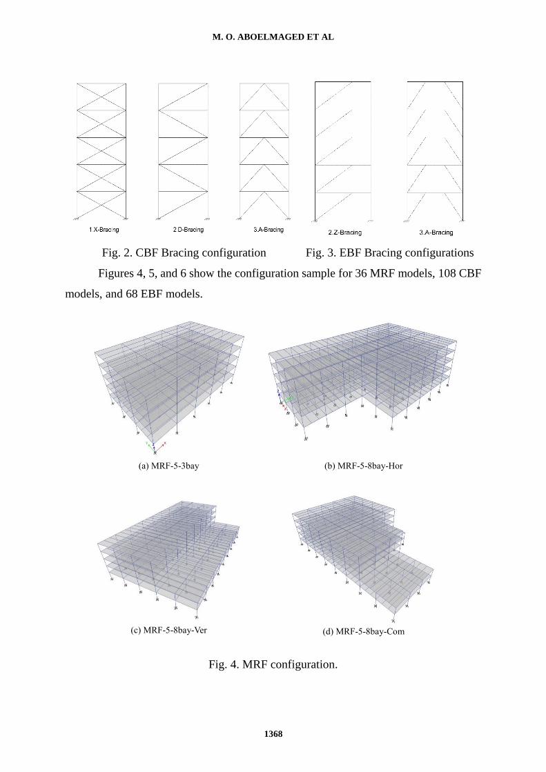
is added for CBF and EBF, which refers to the bracing configuration, one for X bracing,
two for A bracing and three for D bracing in CBF and Z bracing in EBF, number one is
excluded from EBF. Figures 2 and 3 show the bracing configuration.
Nu
mb
er o
f B
ays
Number of Bays
Buil
din
g h
eig
ht
Number of Bays
(a)
(b)
(h)
(c)
a) Horizontal irregularities b) Vertical irregularities
Fig. 1. Horizontal and vertical irregularity concept.
M. O. ABOELMAGED ET AL
1368
Fig. 2. CBF Bracing configuration Fig. 3. EBF Bracing configurations
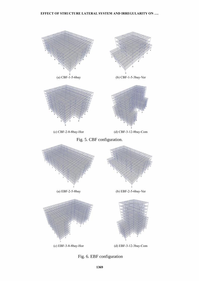
Figures 4, 5, and 6 show the configuration sample for 36 MRF models, 108 CBF
models, and 68 EBF models.
(a) MRF-5-3bay
(b) MRF-5-8bay-Hor
(c) MRF-5-8bay-Ver
(d) MRF-5-8bay-Com
Fig. 4. MRF configuration.
EFFECT OF STRUCTURE LATERAL SYSTEM AND IRREGULARITY ON ….
1369
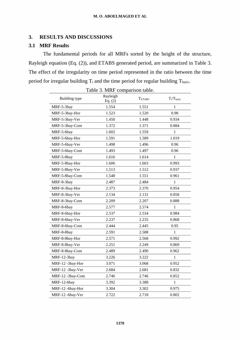
(a) CBF-1-5-6bay
(b) CBF-1-5-3bay-Ver
(c) CBF-2-8-8bay-Hor
(d) CBF-3-12-8bay-Com
Fig. 5. CBF configuration.
(a) EBF-2-5-8bay
(b) EBF-2-5-6bay-Ver
(c) EBF-3-8-8bay-Hor
(d) EBF-3-12-3bay-Com
Fig. 6. EBF configuration
M. O. ABOELMAGED ET AL
1370
3. RESULTS AND DISCUSSIONS
3.1 MRF Results
The fundamental periods for all MRFs sorted by the height of the structure,
Rayleigh equation (Eq. (2)), and ETABS generated period, are summarized in Table 3.
The effect of the irregularity on time period represented in the ratio between the time
period for irregular building Ti and the time period for regular building Tbasic.
Table 3. MRF comparison table.
Building type Rayleigh
Eq. (2) TETABS Ti/Tbasic
MRF-5-3bay 1.554 1.551 1
MRF-5-3bay-Hor 1.523 1.520 0.98
MRF-5-3bay-Ver 1.450 1.448 0.934
MRF-5-3bay-Com 1.372 1.371 0.884
MRF-5-6bay 1.602 1.559 1
MRF-5-6bay-Hor 1.591 1.589 1.019
MRF-5-6bay-Ver 1.498 1.496 0.96
MRF-5-6bay-Com 1.493 1.497 0.96
MRF-5-8bay 1.616 1.614 1
MRF-5-8bay-Hor 1.606 1.603 0.993
MRF-5-8bay-Ver 1.513 1.512 0.937
MRF-5-8bay-Com 1.548 1.551 0.961
MRF-8-3bay 2.487 2.484 1
MRF-8-3bay-Hor 2.373 2.370 0.954
MRF-8-3bay-Ver 2.134 2.131 0.858
MRF-8-3bay-Com 2.209 2.207 0.888
MRF-8-6bay 2.577 2.574 1
MRF-8-6bay-Hor 2.537 2.534 0.984
MRF-8-6bay-Ver 2.237 2.235 0.868
MRF-8-6bay-Com 2.444 2.445 0.95
MRF-8-8bay 2.591 2.588 1
MRF-8-8bay-Hor 2.571 2.568 0.992
MRF-8-8bay-Ver 2.251 2.249 0.869
MRF-8-8bay-Com 2.489 2.490 0.962
MRF-12-3bay 3.226 3.222 1
MRF-12 -3bay-Hor 3.071 3.068 0.952
MRF-12 -3bay-Ver 2.684 2.681 0.832
MRF-12 -3bay-Com 2.746 2.746 0.852
MRF-12-6bay 3.392 3.388 1
MRF-12 -6bay-Hor 3.304 3.302 0.975
MRF-12 -6bay-Ver 2.722 2.718 0.802
EFFECT OF STRUCTURE LATERAL SYSTEM AND IRREGULARITY ON ….
1371
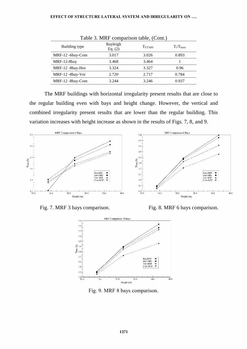
Table 3. MRF comparison table, (Cont.)
Building type Rayleigh
Eq. (2) TETABS Ti/Tbasic
MRF-12 -6bay-Com 3.017 3.026 0.893
MRF-12-8bay 3.468 3.464 1
MRF-12 -8bay-Hor 3.324 3.327 0.96
MRF-12 -8bay-Ver 2.720 2.717 0.784
MRF-12 -8bay-Com 3.244 3.246 0.937
The MRF buildings with horizontal irregularity present results that are close to
the regular building even with bays and height change. However, the vertical and
combined irregularity present results that are lower than the regular building. This
variation increases with height increase as shown in the results of Figs. 7, 8, and 9.
Fig. 7. MRF 3 bays comparison. Fig. 8. MRF 6 bays comparison.
Fig. 9. MRF 8 bays comparison.
M. O. ABOELMAGED ET AL
1372
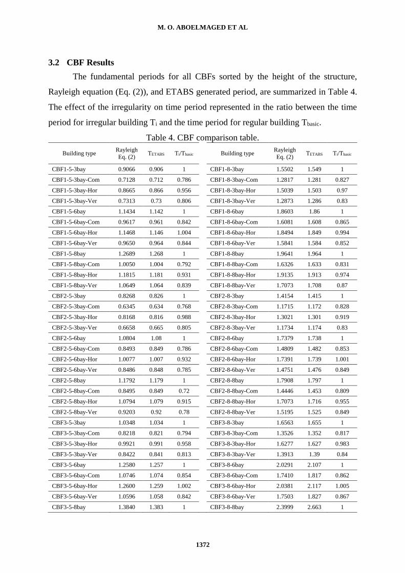
3.2 CBF Results
The fundamental periods for all CBFs sorted by the height of the structure,
Rayleigh equation (Eq. (2)), and ETABS generated period, are summarized in Table 4.
The effect of the irregularity on time period represented in the ratio between the time
period for irregular building Ti and the time period for regular building Tbasic.
Table 4. CBF comparison table.
Building type Rayleigh
Eq. (2) TETABS Ti/Tbasic Building type
Rayleigh
Eq. (2) TETABS Ti/Tbasic
CBF1-5-3bay 0.9066 0.906 1
CBF1-8-3bay 1.5502 1.549 1
CBF1-5-3bay-Com 0.7128 0.712 0.786
CBF1-8-3bay-Com 1.2817 1.281 0.827
CBF1-5-3bay-Hor 0.8665 0.866 0.956
CBF1-8-3bay-Hor 1.5039 1.503 0.97
CBF1-5-3bay-Ver 0.7313 0.73 0.806
CBF1-8-3bay-Ver 1.2873 1.286 0.83
CBF1-5-6bay 1.1434 1.142 1
CBF1-8-6bay 1.8603 1.86 1
CBF1-5-6bay-Com 0.9617 0.961 0.842
CBF1-8-6bay-Com 1.6081 1.608 0.865
CBF1-5-6bay-Hor 1.1468 1.146 1.004
CBF1-8-6bay-Hor 1.8494 1.849 0.994
CBF1-5-6bay-Ver 0.9650 0.964 0.844
CBF1-8-6bay-Ver 1.5841 1.584 0.852
CBF1-5-8bay 1.2689 1.268 1
CBF1-8-8bay 1.9641 1.964 1
CBF1-5-8bay-Com 1.0050 1.004 0.792
CBF1-8-8bay-Com 1.6326 1.633 0.831
CBF1-5-8bay-Hor 1.1815 1.181 0.931
CBF1-8-8bay-Hor 1.9135 1.913 0.974
CBF1-5-8bay-Ver 1.0649 1.064 0.839
CBF1-8-8bay-Ver 1.7073 1.708 0.87
CBF2-5-3bay 0.8268 0.826 1
CBF2-8-3bay 1.4154 1.415 1
CBF2-5-3bay-Com 0.6345 0.634 0.768
CBF2-8-3bay-Com 1.1715 1.172 0.828
CBF2-5-3bay-Hor 0.8168 0.816 0.988
CBF2-8-3bay-Hor 1.3021 1.301 0.919
CBF2-5-3bay-Ver 0.6658 0.665 0.805
CBF2-8-3bay-Ver 1.1734 1.174 0.83
CBF2-5-6bay 1.0804 1.08 1
CBF2-8-6bay 1.7379 1.738 1
CBF2-5-6bay-Com 0.8493 0.849 0.786
CBF2-8-6bay-Com 1.4809 1.482 0.853
CBF2-5-6bay-Hor 1.0077 1.007 0.932
CBF2-8-6bay-Hor 1.7391 1.739 1.001
CBF2-5-6bay-Ver 0.8486 0.848 0.785
CBF2-8-6bay-Ver 1.4751 1.476 0.849
CBF2-5-8bay 1.1792 1.179 1
CBF2-8-8bay 1.7908 1.797 1
CBF2-5-8bay-Com 0.8495 0.849 0.72
CBF2-8-8bay-Com 1.4446 1.453 0.809
CBF2-5-8bay-Hor 1.0794 1.079 0.915
CBF2-8-8bay-Hor 1.7073 1.716 0.955
CBF2-5-8bay-Ver 0.9203 0.92 0.78
CBF2-8-8bay-Ver 1.5195 1.525 0.849
CBF3-5-3bay 1.0348 1.034 1
CBF3-8-3bay 1.6563 1.655 1
CBF3-5-3bay-Com 0.8218 0.821 0.794
CBF3-8-3bay-Com 1.3526 1.352 0.817
CBF3-5-3bay-Hor 0.9921 0.991 0.958
CBF3-8-3bay-Hor 1.6277 1.627 0.983
CBF3-5-3bay-Ver 0.8422 0.841 0.813
CBF3-8-3bay-Ver 1.3913 1.39 0.84
CBF3-5-6bay 1.2580 1.257 1
CBF3-8-6bay 2.0291 2.107 1
CBF3-5-6bay-Com 1.0746 1.074 0.854
CBF3-8-6bay-Com 1.7410 1.817 0.862
CBF3-5-6bay-Hor 1.2600 1.259 1.002
CBF3-8-6bay-Hor 2.0381 2.117 1.005
CBF3-5-6bay-Ver 1.0596 1.058 0.842
CBF3-8-6bay-Ver 1.7503 1.827 0.867
CBF3-5-8bay 1.3840 1.383 1
CBF3-8-8bay 2.3999 2.663 1
EFFECT OF STRUCTURE LATERAL SYSTEM AND IRREGULARITY ON ….
1373
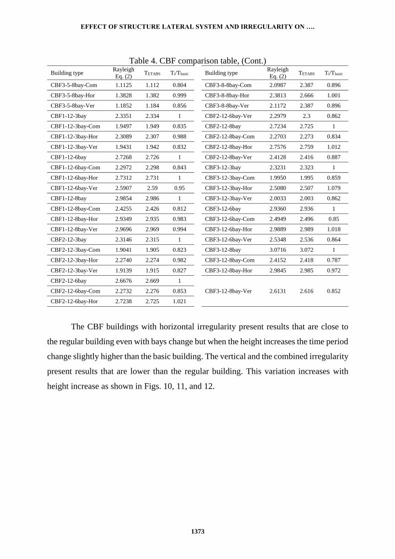
Table 4. CBF comparison table, (Cont.)
Building type Rayleigh
Eq. (2) TETABS Ti/Tbasic
Building type
Rayleigh
Eq. (2) TETABS Ti/Tbasic
CBF3-5-8bay-Com 1.1125 1.112 0.804
CBF3-8-8bay-Com 2.0987 2.387 0.896
CBF3-5-8bay-Hor 1.3828 1.382 0.999
CBF3-8-8bay-Hor 2.3813 2.666 1.001
CBF3-5-8bay-Ver 1.1852 1.184 0.856
CBF3-8-8bay-Ver 2.1172 2.387 0.896
CBF1-12-3bay 2.3351 2.334 1 CBF2-12-6bay-Ver 2.2979 2.3 0.862
CBF1-12-3bay-Com 1.9497 1.949 0.835 CBF2-12-8bay 2.7234 2.725 1
CBF1-12-3bay-Hor 2.3089 2.307 0.988 CBF2-12-8bay-Com 2.2703 2.273 0.834
CBF1-12-3bay-Ver 1.9431 1.942 0.832 CBF2-12-8bay-Hor 2.7576 2.759 1.012
CBF1-12-6bay 2.7268 2.726 1 CBF2-12-8bay-Ver 2.4128 2.416 0.887
CBF1-12-6bay-Com 2.2972 2.298 0.843 CBF3-12-3bay 2.3231 2.323 1
CBF1-12-6bay-Hor 2.7312 2.731 1 CBF3-12-3bay-Com 1.9950 1.995 0.859
CBF1-12-6bay-Ver 2.5907 2.59 0.95 CBF3-12-3bay-Hor 2.5080 2.507 1.079
CBF1-12-8bay 2.9854 2.986 1 CBF3-12-3bay-Ver 2.0033 2.003 0.862
CBF1-12-8bay-Com 2.4255 2.426 0.812 CBF3-12-6bay 2.9360 2.936 1
CBF1-12-8bay-Hor 2.9349 2.935 0.983 CBF3-12-6bay-Com 2.4949 2.496 0.85
CBF1-12-8bay-Ver 2.9696 2.969 0.994 CBF3-12-6bay-Hor 2.9889 2.989 1.018
CBF2-12-3bay 2.3146 2.315 1 CBF3-12-6bay-Ver 2.5348 2.536 0.864
CBF2-12-3bay-Com 1.9041 1.905 0.823 CBF3-12-8bay 3.0716 3.072 1
CBF2-12-3bay-Hor 2.2740 2.274 0.982 CBF3-12-8bay-Com 2.4152 2.418 0.787
CBF2-12-3bay-Ver 1.9139 1.915 0.827 CBF3-12-8bay-Hor 2.9845 2.985 0.972
CBF2-12-6bay 2.6676 2.669 1
CBF3-12-8bay-Ver 2.6131 2.616 0.852 CBF2-12-6bay-Com 2.2732 2.276 0.853
CBF2-12-6bay-Hor 2.7238 2.725 1.021
The CBF buildings with horizontal irregularity present results that are close to
the regular building even with bays change but when the height increases the time period
change slightly higher than the basic building. The vertical and the combined irregularity
present results that are lower than the regular building. This variation increases with
height increase as shown in Figs. 10, 11, and 12.
M. O. ABOELMAGED ET AL
1374
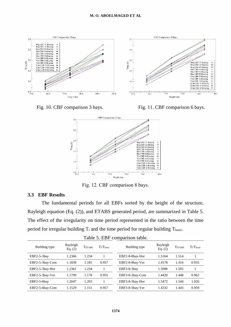
Fig. 10. CBF comparison 3 bays. Fig. 11. CBF comparison 6 bays.
Fig. 12. CBF comparison 8 bays.
3.3 EBF Results
The fundamental periods for all EBFs sorted by the height of the structure,
Rayleigh equation (Eq. (2)), and ETABS generated period, are summarized in Table 5.
The effect of the irregularity on time period represented in the ratio between the time
period for irregular building Ti and the time period for regular building Tbasic.
Table 5. EBF comparison table.
Building type Rayleigh
Eq. (2) TETABS Ti/Tbasic Building type
Rayleigh
Eq. (2) TETABS Ti/Tbasic
EBF2-5-3bay 1.2366 1.234 1
EBF2-8-8bay-Hor 1.5164 1.514 1
EBF2-5-3bay-Com 1.1839 1.181 0.957
EBF2-8-8bay-Ver 1.4178 1.416 0.935
EBF2-5-3bay-Hor 1.2361 1.234 1
EBF3-8-3bay 1.5086 1.505 1
EBF2-5-3bay-Ver 1.1799 1.178 0.955
EBF3-8-3bay-Com 1.4420 1.448 0.962
EBF2-5-6bay 1.2047 1.203 1
EBF3-8-3bay-Hor 1.5472 1.544 1.026
EBF2-5-6bay-Com 1.1529 1.151 0.957
EBF3-8-3bay-Ver 1.4332 1.443 0.959
EFFECT OF STRUCTURE LATERAL SYSTEM AND IRREGULARITY ON ….
1375
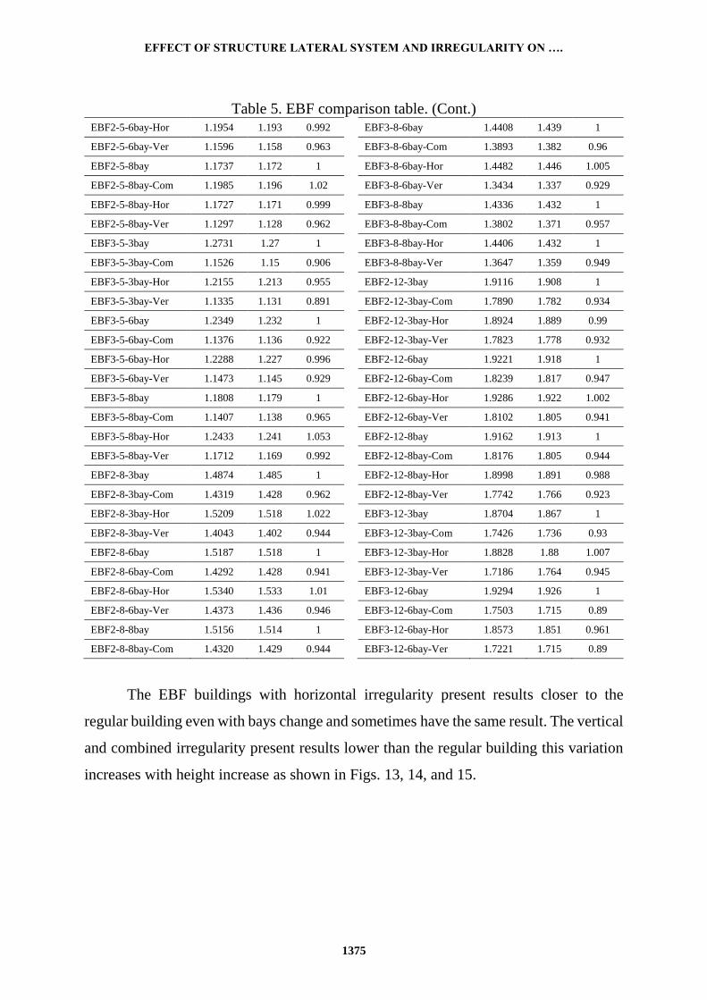
Table 5. EBF comparison table. (Cont.) EBF2-5-6bay-Hor 1.1954 1.193 0.992
EBF3-8-6bay 1.4408 1.439 1
EBF2-5-6bay-Ver 1.1596 1.158 0.963
EBF3-8-6bay-Com 1.3893 1.382 0.96
EBF2-5-8bay 1.1737 1.172 1
EBF3-8-6bay-Hor 1.4482 1.446 1.005
EBF2-5-8bay-Com 1.1985 1.196 1.02
EBF3-8-6bay-Ver 1.3434 1.337 0.929
EBF2-5-8bay-Hor 1.1727 1.171 0.999
EBF3-8-8bay 1.4336 1.432 1
EBF2-5-8bay-Ver 1.1297 1.128 0.962
EBF3-8-8bay-Com 1.3802 1.371 0.957
EBF3-5-3bay 1.2731 1.27 1
EBF3-8-8bay-Hor 1.4406 1.432 1
EBF3-5-3bay-Com 1.1526 1.15 0.906
EBF3-8-8bay-Ver 1.3647 1.359 0.949
EBF3-5-3bay-Hor 1.2155 1.213 0.955
EBF2-12-3bay 1.9116 1.908 1
EBF3-5-3bay-Ver 1.1335 1.131 0.891
EBF2-12-3bay-Com 1.7890 1.782 0.934
EBF3-5-6bay 1.2349 1.232 1
EBF2-12-3bay-Hor 1.8924 1.889 0.99
EBF3-5-6bay-Com 1.1376 1.136 0.922
EBF2-12-3bay-Ver 1.7823 1.778 0.932
EBF3-5-6bay-Hor 1.2288 1.227 0.996
EBF2-12-6bay 1.9221 1.918 1
EBF3-5-6bay-Ver 1.1473 1.145 0.929
EBF2-12-6bay-Com 1.8239 1.817 0.947
EBF3-5-8bay 1.1808 1.179 1
EBF2-12-6bay-Hor 1.9286 1.922 1.002
EBF3-5-8bay-Com 1.1407 1.138 0.965
EBF2-12-6bay-Ver 1.8102 1.805 0.941
EBF3-5-8bay-Hor 1.2433 1.241 1.053
EBF2-12-8bay 1.9162 1.913 1
EBF3-5-8bay-Ver 1.1712 1.169 0.992
EBF2-12-8bay-Com 1.8176 1.805 0.944
EBF2-8-3bay 1.4874 1.485 1
EBF2-12-8bay-Hor 1.8998 1.891 0.988
EBF2-8-3bay-Com 1.4319 1.428 0.962
EBF2-12-8bay-Ver 1.7742 1.766 0.923
EBF2-8-3bay-Hor 1.5209 1.518 1.022
EBF3-12-3bay 1.8704 1.867 1
EBF2-8-3bay-Ver 1.4043 1.402 0.944
EBF3-12-3bay-Com 1.7426 1.736 0.93
EBF2-8-6bay 1.5187 1.518 1
EBF3-12-3bay-Hor 1.8828 1.88 1.007
EBF2-8-6bay-Com 1.4292 1.428 0.941
EBF3-12-3bay-Ver 1.7186 1.764 0.945
EBF2-8-6bay-Hor 1.5340 1.533 1.01
EBF3-12-6bay 1.9294 1.926 1
EBF2-8-6bay-Ver 1.4373 1.436 0.946
EBF3-12-6bay-Com 1.7503 1.715 0.89
EBF2-8-8bay 1.5156 1.514 1
EBF3-12-6bay-Hor 1.8573 1.851 0.961
EBF2-8-8bay-Com 1.4320 1.429 0.944
EBF3-12-6bay-Ver 1.7221 1.715 0.89
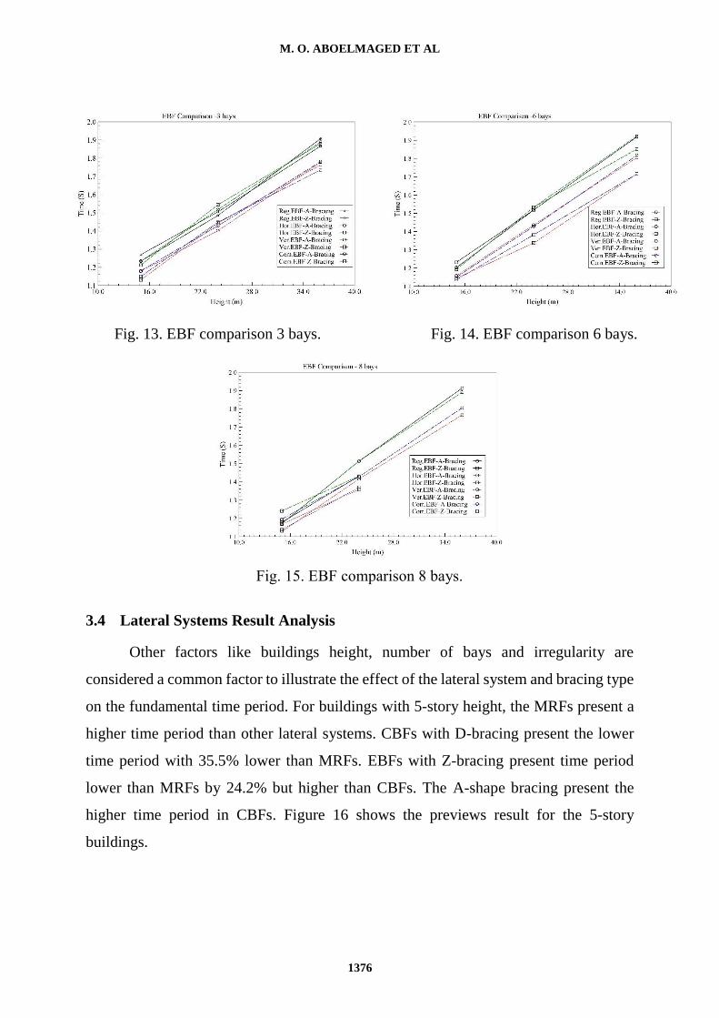
The EBF buildings with horizontal irregularity present results closer to the
regular building even with bays change and sometimes have the same result. The vertical
and combined irregularity present results lower than the regular building this variation
increases with height increase as shown in Figs. 13, 14, and 15.
M. O. ABOELMAGED ET AL
1376
Fig. 13. EBF comparison 3 bays. Fig. 14. EBF comparison 6 bays.
Fig. 15. EBF comparison 8 bays.
3.4 Lateral Systems Result Analysis
Other factors like buildings height, number of bays and irregularity are
considered a common factor to illustrate the effect of the lateral system and bracing type
on the fundamental time period. For buildings with 5-story height, the MRFs present a
higher time period than other lateral systems. CBFs with D-bracing present the lower
time period with 35.5% lower than MRFs. EBFs with Z-bracing present time period
lower than MRFs by 24.2% but higher than CBFs. The A-shape bracing present the
higher time period in CBFs. Figure 16 shows the previews result for the 5-story
buildings.
EFFECT OF STRUCTURE LATERAL SYSTEM AND IRREGULARITY ON ….
1377
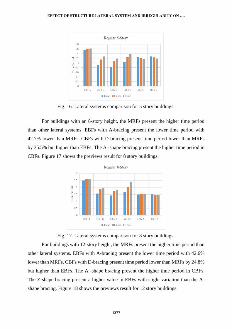
Fig. 16. Lateral systems comparison for 5 story buildings.
For buildings with an 8-story height, the MRFs present the higher time period
than other lateral systems. EBFs with A-bracing present the lower time period with
42.7% lower than MRFs. CBFs with D-bracing present time period lower than MRFs
by 35.5% but higher than EBFs. The A -shape bracing present the higher time period in
CBFs. Figure 17 shows the previews result for 8 story buildings.
Fig. 17. Lateral systems comparison for 8 story buildings.
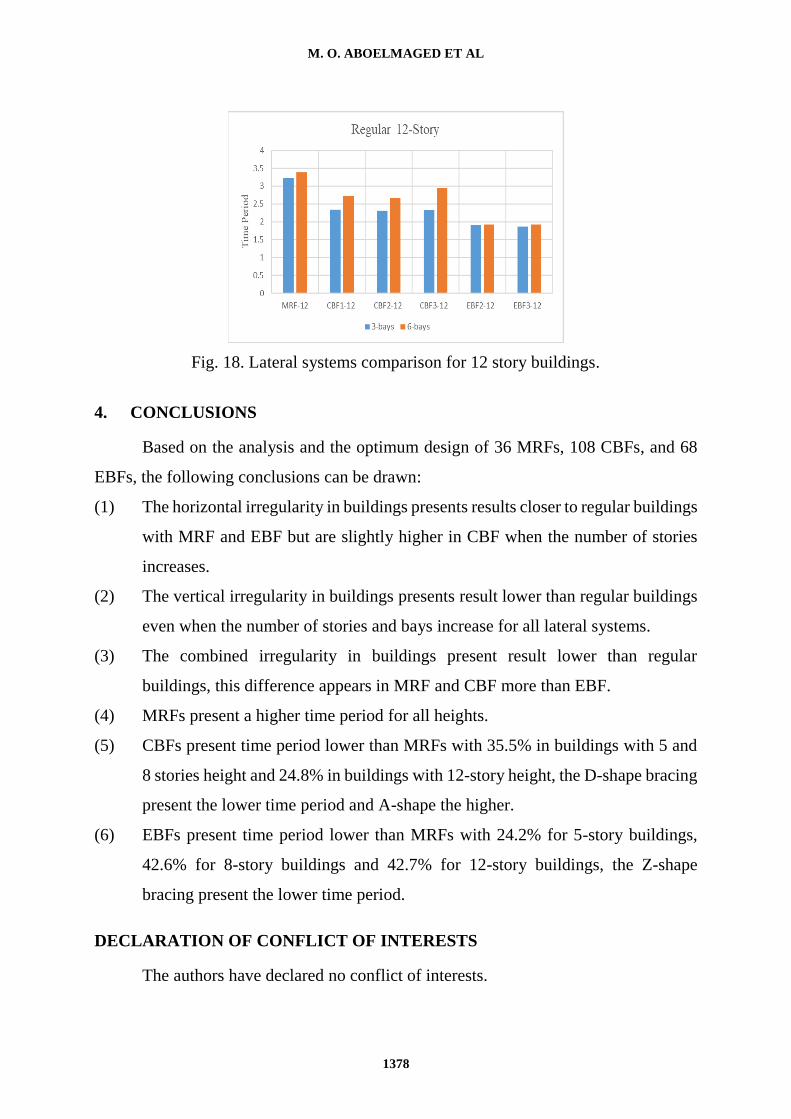
For buildings with 12-story height, the MRFs present the higher time period than
other lateral systems. EBFs with A-bracing present the lower time period with 42.6%
lower than MRFs. CBFs with D-bracing present time period lower than MRFs by 24.8%
but higher than EBFs. The A -shape bracing present the higher time period in CBFs.
The Z-shape bracing present a higher value in EBFs with slight variation than the A-
shape bracing. Figure 18 shows the previews result for 12 story buildings.
M. O. ABOELMAGED ET AL
1378
Fig. 18. Lateral systems comparison for 12 story buildings.
4. CONCLUSIONS
Based on the analysis and the optimum design of 36 MRFs, 108 CBFs, and 68
EBFs, the following conclusions can be drawn:
(1) The horizontal irregularity in buildings presents results closer to regular buildings
with MRF and EBF but are slightly higher in CBF when the number of stories
increases.
(2) The vertical irregularity in buildings presents result lower than regular buildings
even when the number of stories and bays increase for all lateral systems.
(3) The combined irregularity in buildings present result lower than regular
buildings, this difference appears in MRF and CBF more than EBF.
(4) MRFs present a higher time period for all heights.
(5) CBFs present time period lower than MRFs with 35.5% in buildings with 5 and
8 stories height and 24.8% in buildings with 12-story height, the D-shape bracing
present the lower time period and A-shape the higher.
(6) EBFs present time period lower than MRFs with 24.2% for 5-story buildings,
42.6% for 8-story buildings and 42.7% for 12-story buildings, the Z-shape
bracing present the lower time period.
DECLARATION OF CONFLICT OF INTERESTS
The authors have declared no conflict of interests.
EFFECT OF STRUCTURE LATERAL SYSTEM AND IRREGULARITY ON ….
1379
REFERENCES
1. Tremblay, R., "Fundamental Periods of Vibration of Braced Steel Frames for
Seismic Design", Earthquake Spectra, Vol. 21, pp. 833-860, 2005
2. Goel, R.K., and Chopra, A.K., "Period Formulas for Moment-Resisting Frame
Buildings", Journal of Structural Engineering, Vol.123, pp. 1454-1461, 1997.
3. Euro Code 8, "Design of Structures for Earthquake Resistance", European
Committee for Standardization, 1998.
4. ECP 201, "The Egyptian Code for Loads and Forces in Construction and
Buildings", Housing and Building National Research Center, Cairo, Egypt, 2012.
5. ASCE/SEI 7-10., "Minimum Design Loads for Buildings and Other Structures",
American Society of Civil Engineers, Virginia, 2010.
6. UBC, "Uniform Building Code", International Conference of Building Officials,
1997.
7. Cinitha, A., "A Rational Approach for Fundamental Period of Low and Medium
Rise Steel Building Frames", International Journal of Modern Engineering
Research, Vol. 2, pp. 3340-3346, 2012.
8. Sheikh, H., and A. Massumi "Effects of Bracing Configuration on Seismic
Behavior of Tall Steel Structures Subjected to Earthquake Ground Motions",
Proceedings of the 10th US National Conference on Earthquake Engineering,
Anchorage, Alaska. 2014.
9. Amini, A., M. Majd, and M. Hosseini, "A Study on the Effect of Bracing
Arrangement in the Seismic Behavior Buildings with Various Concentric Bracings
by Nonlinear Static and Dynamic Analyses", Fifteenth World Conference on
Earthquake Engineering, Lisbon, Portugal, 2012.
10. Pandit, L., and Shinde, R., "Study of Effect of Bracing on Critical Story of High-
Rise Frame Structure", International Journal of Engineering Research and General
Science, Vol. 3, 2015.
11. Hemmati, A., Kheyroddin, A., "Behavior of Large-Scale Bracing System in Tall
Buildings Subjected to Earthquake Loads", Journal of Civil Engineering and
Management, Vol. 2, pp. 206-216, 2013.
12. ECP 205, "Egyptian Code of Practice for Steel Construction and Bridges
Allowable Stress Design", Housing and Building National Research Centre, Cairo,
Egypt, 2001.
13. ANSI/AISC 360-10, "An American National Standard - Specification for
Structural Steel Building", Chicago, Illinois, 2010.
14. Yousef, A. M., El-Metwally, S. E., and El-Mandouh., M. A., "Seismic Response
of Vertically Irregular HSC Moment-Resisting Building Frames", Journal of
Engineering and Applied Science, Vol. 57, No. 5, pp. 409-430, 2010.
M. O. ABOELMAGED ET AL
1380
على زمن التردد الأساسي للمنشآت المعدنيةتأثير النظام الإنشائي الجانبي وعدم الانتظام
لبحث تأثير النظام الجانبي وعدم الانتظام على زمن التردد الطبيعي للمنشآآآآآآآآآآآآآآآ المعدني يدرس ا (CBF)شآآآآآآآكالا مرتزتي الت تي 108و (MRF)إطاراً مقاوماً العزوم 36حيث تمت نمذج ودراسآآآآآآآ
5باسآآآتمدام ارنامل البتابهذ ذا وتع اعتبار ث ث ارتااعا (EBF)شآآآكالا لا مرتزتي الت تي 68ودور بالإضآآآآآآا الى ث ث ان اد من عدم الانتظام و ى عدم الانتظام الرلأسآآآآآآي وا، قي والمجم ذ 12و 8و
وبعد الانتهاء من التحليل والتصآآآآآآآآميع ا،منل للمباني تمت مقارن نتالل زمن التردد الطبيعي للمنشآآآآآآآآ م المسآآآآآآآآآتمدم با،ي اد والتي معتمد معظمها على ارتااد المبنى قن واثبتت نتيج البحث لأ النظام نظالر ا
الإنشالي الجانبي للمباني وعدم انتظام المبنى لهما تأثير تبير على زمن التردد الطبيعي للمباني ذا ناه الارتااد.