Embed Size (px)
Citation preview
Effect of Oval Shape Tunnel on Existing Buildings
Under Seismic Loading
Dr. Dhatrak A. I. *
*Associate Professor, Department of Civil Engineering,
Government College of Engineering, Amravati, Maharashtra, India.
Mr. Dhengle Sagar. D
**
**PG Student, Department of Civil Engineering,
Government College of Engineering, Amravati,
Maharashtra, India.
Abstract—- This paper deals with analysis of the time history
response of the soil profile surrounding tunnel during
earthquakes. The analysis presented illustrates the behavior of
buildings due to oval shape tunneling under seismic loading
condition. Generally tunnels have a fairly high safety against
earthquakes. However, at the earth surface the reaction to the
earthquake action may lead to more complicated consequences.
The proposed approach can also be used for estimation of
dynamic load influence on development of differential settlement
for nearby structure. the impact of the earthquakes on
underground and ground structures and it can be evaluated,
whether the amount of variations in displacements are in the
allowable ranges, and what measures are needed to save the
structures in case of excessive displacement A real tunnel model
which is subjected to earthquake forces was considered and for
the purpose of analysis modified numerical program MIDAS 2D
was used
Keywords— Tunnel, excavation, superstructure, Earthquake,
MIDAS 2D, Displacement
I. INTRODUCTION
One of the most important factors affecting the
design of the structures is the impact of the seismic loadings
on the design displacements. Whereas, the influences of the
near structures on the existing buildings, which sometimes can
cause great changes in forces and displacements. Thus, the
induced displacement in the adjacent buildings due to newly
constructed underground tunnel will be investigated in this
study. The behavior of the super structures, such as buildings,
bridges, under seismic conditions is highly affected by the
underlying soil layer. So far, extensive studies have been
carried out to know the impact of the earthquakes on
underground and ground structures and it can be evaluated,
whether the amount of variations in displacements are in the
allowable ranges, and what measures are needed to save the
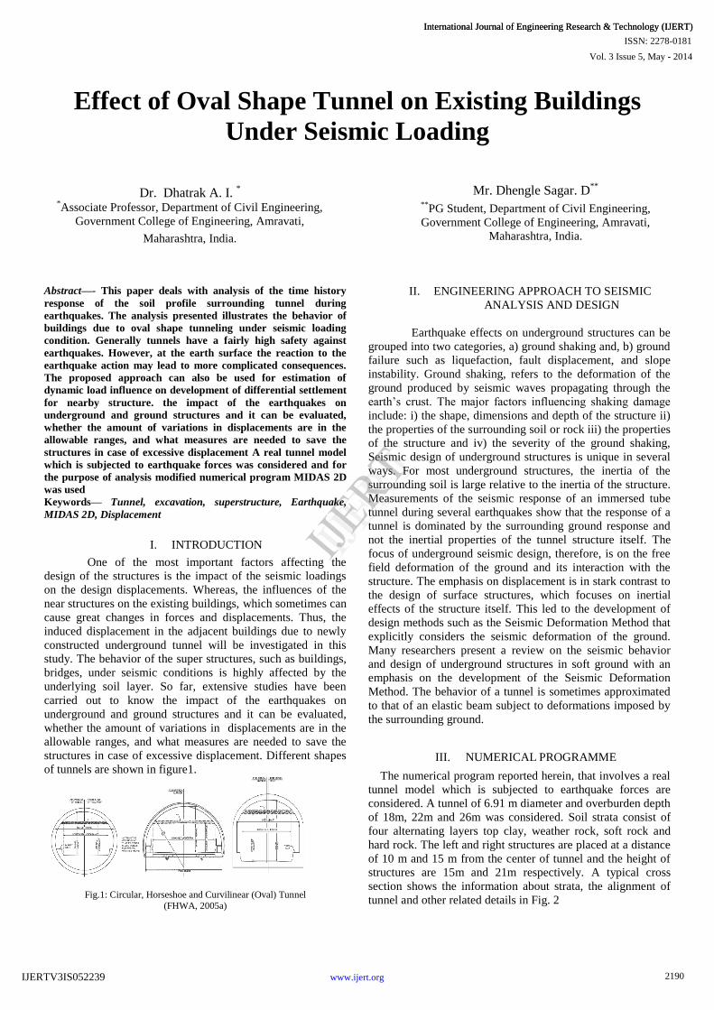
structures in case of excessive displacement. Different shapes
of tunnels are shown in figure1.
Fig.1: Circular, Horseshoe and Curvilinear (Oval) Tunnel
(FHWA, 2005a)
II. ENGINEERING APPROACH TO SEISMIC
ANALYSIS AND DESIGN
Earthquake effects on underground structures can be
grouped into two categories, a) ground shaking and, b) ground
failure such as liquefaction, fault displacement, and slope
instability. Ground shaking, refers to the deformation of the
ground produced by seismic waves propagating through the
earth’s crust. The major factors influencing shaking damage
include: i) the shape, dimensions and depth of the structure ii)
the properties of the surrounding soil or rock iii) the properties
of the structure and iv) the severity of the ground shaking,
Seismic design of underground structures is unique in several
ways. For most underground structures, the inertia of the
surrounding soil is large relative to the inertia of the structure.
Measurements of the seismic response of an immersed tube
tunnel during several earthquakes show that the response of a
tunnel is dominated by the surrounding ground response and
not the inertial properties of the tunnel structure itself. The
focus of underground seismic design, therefore, is on the free
field deformation of the ground and its interaction with the
structure. The emphasis on displacement is in stark contrast to
the design of surface structures, which focuses on inertial
effects of the structure itself. This led to the development of
design methods such as the Seismic Deformation Method that
explicitly considers the seismic deformation of the ground.
Many researchers present a review on the seismic behavior
and design of underground structures in soft ground with an
emphasis on the development of the Seismic Deformation
Method. The behavior of a tunnel is sometimes approximated
to that of an elastic beam subject to deformations imposed by
the surrounding ground.
III. NUMERICAL PROGRAMME
The numerical program reported herein, that involves a real
tunnel model which is subjected to earthquake forces are
considered. A tunnel of 6.91 m diameter and overburden depth
of 18m, 22m and 26m was considered. Soil strata consist of
four alternating layers top clay, weather rock, soft rock and
hard rock. The left and right structures are placed at a distance
of 10 m and 15 m from the center of tunnel and the height of
structures are 15m and 21m respectively. A typical cross
section shows the information about strata, the alignment of
tunnel and other related details in Fig. 2
2190
Vol. 3 Issue 5, May - 2014
International Journal of Engineering Research & Technology (IJERT)
IJERT
IJERT
ISSN: 2278-0181
www.ijert.orgIJERTV3IS052239
International Journal of Engineering Research & Technology (IJERT)
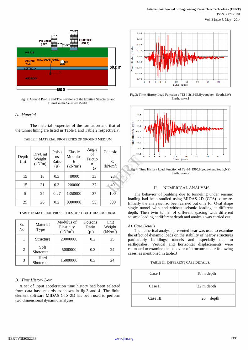
Fig. 2: Ground Profile and The Positions of the Existing Structures and
Tunnel in the Selected Model.
A. Material
The material properties of the formation and that of
the tunnel lining are listed in Table 1 and Table 2 respectively.
TABLE I : MATERIAL PROPERTIES OF GROUND MEDIUM
Depth
(m)
DryUnit
Weight
(kN/m)
Poiso
ns
Ratio
(µ)
Elastic
Modulus
E
(kN/m2)
Angle
of
Frictio
n
Ø
Cohesio
n
C
(kN/m2)
15 18 0.3 40000 33 28
15 21 0.3 200000 37 40
5 24 0.27 1350000 37 100
25 26 0.2 8900000 55 500
TABLE II: MATERIAL PROPERTIES OF STRUCTURAL MEDIUM.
Sr.
No
Material
Type
Modulus of
Elasticity
(kN/m2)
Poisons
Ratio
(µ )
Unit
Weight
(kN/m3)
1 Structure 20000000 0.2 25
2 Soft
Shotcrete 5000000 0.3 24
3 Hard
Shotcrete 15000000 0.3 24
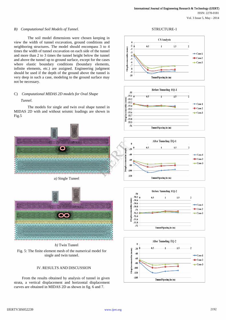
B. Time History Data
A set of input acceleration time history had been selected
from data base records as shown in fig.3 and 4. The finite
element software MIDAS GTS 2D has been used to perform
two dimensional dynamic analyses.
Fig.3: Time History Load Function of T2-I-2(1995,Hyougoken_South,EW)
Earthquake.1
Fig 4: Time History Load Function of T2-I-1(1995,Hyougoken_South,NS)
Earthquake.2
II. NUMERICAL ANALYSIS
The behavior of building due to tunneling under seismic loading had been studied using MIDAS 2D (GTS) software. Initially the analysis had been carried out only for Oval shape single tunnel with and without seismic loading at different depth. Then twin tunnel of different spacing with different seismic loading at different depth and analysis was carried out. A) Case Details
The numerical analysis presented hear was used to examine the effect of dynamic loads on the stability of nearby structures particularly buildings, tunnels and especially due to earthquakes. Vertical and horizontal displacements were estimated to examine the behavior of structure under following cases, as mentioned in table.3
TABLE III: DIFFERENT CASE DETAILS.
Case I 18 m depth
Case II 22 m depth
Case III 26 depth
2191
Vol. 3 Issue 5, May - 2014
International Journal of Engineering Research & Technology (IJERT)
IJERT
IJERT
ISSN: 2278-0181
www.ijert.orgIJERTV3IS052239
International Journal of Engineering Research & Technology (IJERT)
B) Computational Soil Models of Tunnel.
The soil model dimensions were chosen keeping in
view the width of tunnel excavation, ground conditions and
neighboring structures. The model should encompass 3 to 4
times the width of tunnel excavation on each side of the tunnel
and more than 2 to 3 times the tunnel height below the tunnel
and above the tunnel up to ground surface, except for the cases
where elastic boundary conditions (boundary elements,
infinite elements, etc.) are assigned. Engineering judgment
should be used if the depth of the ground above the tunnel is
very deep in such a case, modeling to the ground surface may
not be necessary.
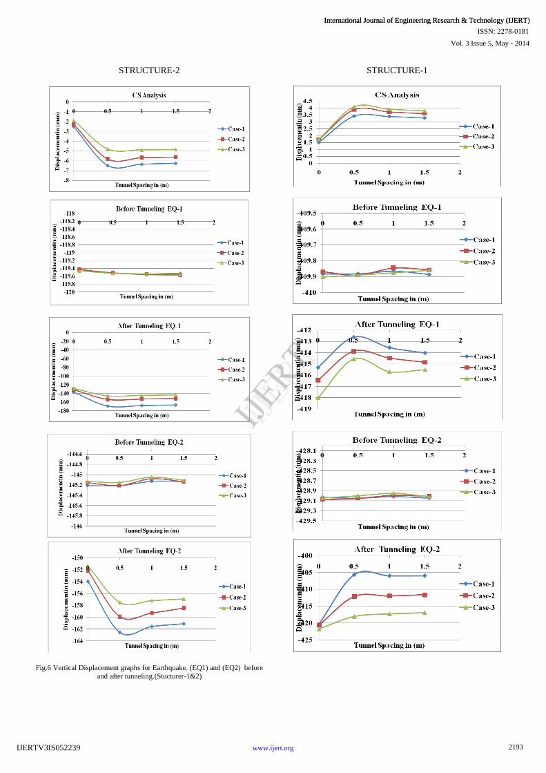
C) Computational MIDAS 2D models for Oval Shape
Tunnel.
The models for single and twin oval shape tunnel in
MIDAS 2D with and without seismic loadings are shown in
Fig.5
a) Single Tuneel
b) Twin Tuneel
Fig. 5: The finite element mesh of the numerical model for
single and twin tunnel.
IV. RESULTS AND DISCUSSION
From the results obtained by analysis of tunnel in given
strata, a vertical displacement and horizontal displacement
curves are obtained in MIDAS 2D as shown in fig. 6 and 7.
STRUCTURE-1
2192
Vol. 3 Issue 5, May - 2014
International Journal of Engineering Research & Technology (IJERT)
IJERT
IJERT
ISSN: 2278-0181
www.ijert.orgIJERTV3IS052239
International Journal of Engineering Research & Technology (IJERT)
STRUCTURE-2
Fig.6 Vertical Displacement graphs for Earthquake. (EQ1) and (EQ2) before
and after tunneling.(Stucturer-1&2)
STRUCTURE-1
2193
Vol. 3 Issue 5, May - 2014
International Journal of Engineering Research & Technology (IJERT)
IJERT
IJERT
ISSN: 2278-0181
www.ijert.orgIJERTV3IS052239
International Journal of Engineering Research & Technology (IJERT)
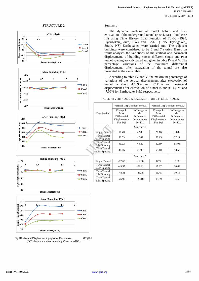
STRUCTURE-2
Fig.7Horizontal Displacement graphs for Earthquakes (EQ1) & (EQ2) before and after tunneling. (Structure-1&2)
Summery
The dynamic analysis of model before and after excavation of the underground tunnel (case I, case II and case III) using Time History Load Function of T2-I-2 (1995, Hyougoken_South, EW) and T2-I-1 (1995, Hyougoken_ South, NS) Earthquakes were carried out. The adjacent buildings were considered to be 5 and 7 stories. Based on result analyses the variations of the vertical and horizontal displacements of building versus different single and twin tunnel spacing are calculated and given in table IV and V. The percentage variations of the maximum differential displacements after excavation of the tunnel are also presented in the same table.
According to table IV and V, the maximum percentage of variations of the vertical displacement after excavation of tunnel is about 47.69% and 57.11% and horizontal displacement after excavation of tunnel is about -1.76% and -7.06% for Earthquake-1 &2 respectively.
TABLE IV: VERTICAL DISPLACEMENT FOR DIFFERENT CASES.
Case Studied
Vertical Displacement For Eq1
Vertical Displacement For Eq2
Change In Max
Differential
Displacement For Eq1
%Change In Max
Differential
Displacement For Eq1
Change In Max
Differential
Displacement For Eq2
%Change In Max
Differential
Displacement For Eq1
Structure 1
Single Tunnel
16.40
22.86
26.16
33.82
Twin Tunnel
0.5m Spacing 50.53
47.69
68.15
57.11
Twin Tunnel
1 M Spacing 43.92
44.22
62.69
55.08
Twin Tunnel
1.5m Spacing 40.06
41.96
59.10
53.59
Structure 2
Single Tunnel
-17.63
-12.86
8.75
5.68
Twin Tunnel
0.5m Spacing -49.55
-29.31
17.37
10.68
Twin Tunnel 1 M Spacing
-48.31
-28.78
16.45
10.18
Twin Tunnel
1.5m Spacing -46.90
-28.18
15.99
9.92
2194
Vol. 3 Issue 5, May - 2014
International Journal of Engineering Research & Technology (IJERT)
IJERT
IJERT
ISSN: 2278-0181
www.ijert.orgIJERTV3IS052239
International Journal of Engineering Research & Technology (IJERT)
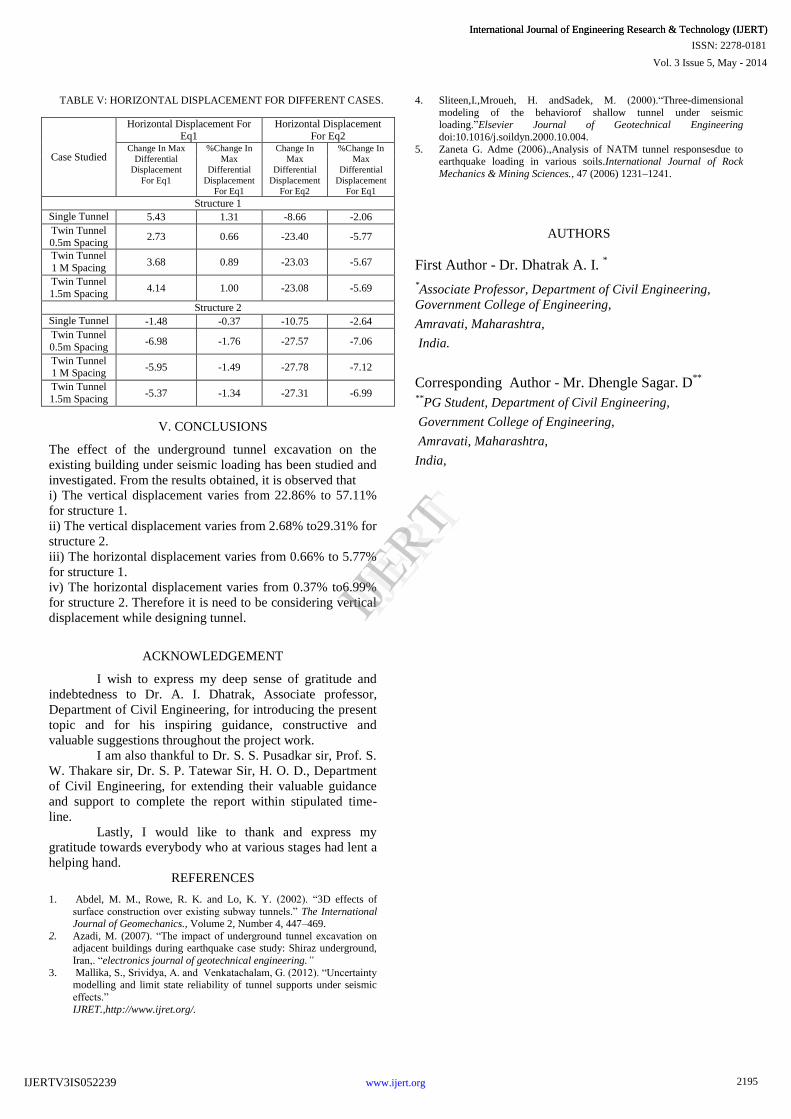
TABLE V: HORIZONTAL DISPLACEMENT FOR DIFFERENT CASES.
Case Studied
Horizontal Displacement For Eq1
Horizontal Displacement
For Eq2
Change In
Max
Differential
Displacement
For Eq1
%Change In
Max
Differential
Displacement
For Eq1
Change In
Max
Differential
Displacement
For Eq2
%Change In
Max
Differential
Displacement
For Eq1
Structure 1
Single Tunnel
5.43
1.31
-8.66
-2.06
Twin Tunnel 0.5m Spacing
2.73
0.66
-23.40
-5.77
Twin Tunnel
1 M Spacing
3.68
0.89
-23.03
-5.67
Twin Tunnel 1.5m Spacing
4.14
1.00
-23.08
-5.69
Structure 2
Single Tunnel
-1.48
-0.37
-10.75
-2.64
Twin Tunnel
0.5m Spacing
-6.98
-1.76
-27.57
-7.06
Twin Tunnel 1 M Spacing
-5.95
-1.49
-27.78
-7.12
Twin Tunnel
1.5m Spacing
-5.37
-1.34
-27.31
-6.99
V. CONCLUSIONS
The effect of the underground tunnel excavation on the
existing building under seismic loading has been studied and
investigated. From the results obtained, it is observed that
i) The vertical displacement varies from 22.86% to 57.11%
for structure 1.
ii) The vertical displacement varies from 2.68% to29.31% for
structure 2.
iii) The horizontal displacement varies from 0.66% to 5.77%
for structure 1.
iv) The horizontal displacement varies from 0.37% to6.99%
for structure 2. Therefore it is need to be considering vertical
displacement while designing tunnel.
ACKNOWLEDGEMENT
I wish to express my deep sense of gratitude and
indebtedness to Dr. A. I. Dhatrak, Associate professor,
Department of Civil Engineering, for introducing the present
topic and for his inspiring guidance, constructive and
valuable suggestions throughout the project work.
I am also thankful to Dr. S. S. Pusadkar sir, Prof. S.
W. Thakare sir, Dr. S. P. Tatewar Sir, H. O. D., Department
of Civil Engineering, for extending their valuable guidance
and support to complete the report within stipulated time-
line.
Lastly, I would like to thank and express my
gratitude towards everybody who at various stages had lent a
helping hand.
REFERENCES
1. Abdel, M. M., Rowe, R. K. and Lo, K. Y. (2002). “3D effects of
surface construction over existing subway tunnels.” The International Journal of Geomechanics., Volume 2, Number 4, 447–469.
2. Azadi, M. (2007). “The impact of underground tunnel excavation on adjacent buildings during earthquake case study: Shiraz underground,
Iran,. “electronics journal of geotechnical engineering.”
3. Mallika, S., Srividya, A. and Venkatachalam, G. (2012). “Uncertainty modelling and limit state reliability of tunnel supports under seismic
effects.”
IJRET.,http://www.ijret.org/.
4. Sliteen,I.,Mroueh, H. andSadek, M. (2000).“Three-dimensional
modeling of the behaviorof shallow tunnel under seismic loading.”Elsevier Journal of Geotechnical Engineering
doi:10.1016/j.soildyn.2000.10.004.
5. Zaneta G. Adme (2006).,Analysis of NATM tunnel responsesdue to earthquake loading in various soils.International Journal of Rock
Mechanics & Mining Sciences., 47 (2006) 1231–1241.
AUTHORS
First Author - Dr. Dhatrak A. I. *
*Associate Professor, Department of Civil Engineering,
Government College of Engineering,
Amravati, Maharashtra,
India.
Corresponding Author - Mr. Dhengle Sagar. D**
**PG Student, Department of Civil Engineering,
Government College of Engineering,
Amravati, Maharashtra,
India,
2195
Vol. 3 Issue 5, May - 2014
International Journal of Engineering Research & Technology (IJERT)
IJERT
IJERT
ISSN: 2278-0181
www.ijert.orgIJERTV3IS052239
International Journal of Engineering Research & Technology (IJERT)