Embed Size (px)
Citation preview
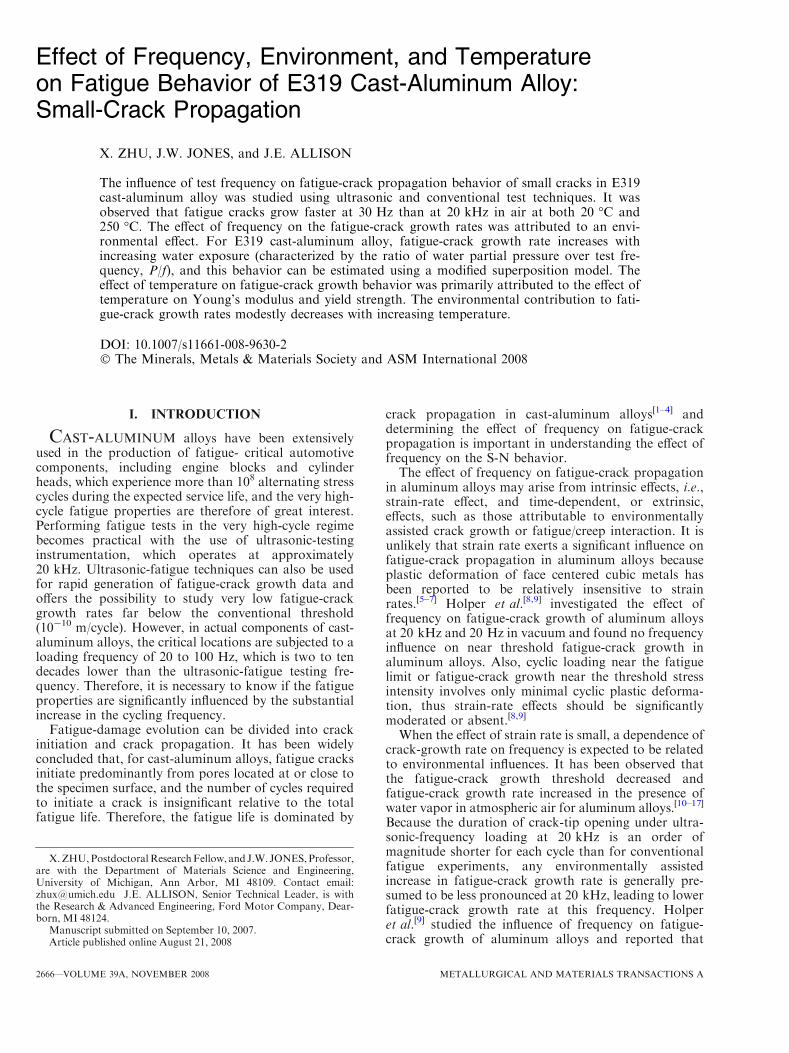
Effect of Frequency, Environment, and Temperatureon Fatigue Behavior of E319 Cast-Aluminum Alloy:Small-Crack Propagation
X. ZHU, J.W. JONES, and J.E. ALLISON
The influence of test frequency on fatigue-crack propagation behavior of small cracks in E319cast-aluminum alloy was studied using ultrasonic and conventional test techniques. It wasobserved that fatigue cracks grow faster at 30 Hz than at 20 kHz in air at both 20 �C and250 �C. The effect of frequency on the fatigue-crack growth rates was attributed to an envi-ronmental effect. For E319 cast-aluminum alloy, fatigue-crack growth rate increases withincreasing water exposure (characterized by the ratio of water partial pressure over test fre-quency, P/f), and this behavior can be estimated using a modified superposition model. Theeffect of temperature on fatigue-crack growth behavior was primarily attributed to the effect oftemperature on Young’s modulus and yield strength. The environmental contribution to fati-gue-crack growth rates modestly decreases with increasing temperature.
DOI: 10.1007/s11661-008-9630-2� The Minerals, Metals & Materials Society and ASM International 2008
I. INTRODUCTION
CAST-ALUMINUM alloys have been extensivelyused in the production of fatigue- critical automotivecomponents, including engine blocks and cylinderheads, which experience more than 108 alternating stresscycles during the expected service life, and the very high-cycle fatigue properties are therefore of great interest.Performing fatigue tests in the very high-cycle regimebecomes practical with the use of ultrasonic-testinginstrumentation, which operates at approximately20 kHz. Ultrasonic-fatigue techniques can also be usedfor rapid generation of fatigue-crack growth data andoffers the possibility to study very low fatigue-crackgrowth rates far below the conventional threshold(10-10 m/cycle). However, in actual components of cast-aluminum alloys, the critical locations are subjected to aloading frequency of 20 to 100 Hz, which is two to tendecades lower than the ultrasonic-fatigue testing fre-quency. Therefore, it is necessary to know if the fatigueproperties are significantly influenced by the substantialincrease in the cycling frequency.
Fatigue-damage evolution can be divided into crackinitiation and crack propagation. It has been widelyconcluded that, for cast-aluminum alloys, fatigue cracksinitiate predominantly from pores located at or close tothe specimen surface, and the number of cycles requiredto initiate a crack is insignificant relative to the totalfatigue life. Therefore, the fatigue life is dominated by
crack propagation in cast-aluminum alloys[1–4] anddetermining the effect of frequency on fatigue-crackpropagation is important in understanding the effect offrequency on the S-N behavior.The effect of frequency on fatigue-crack propagation
in aluminum alloys may arise from intrinsic effects, i.e.,strain-rate effect, and time-dependent, or extrinsic,effects, such as those attributable to environmentallyassisted crack growth or fatigue/creep interaction. It isunlikely that strain rate exerts a significant influence onfatigue-crack propagation in aluminum alloys becauseplastic deformation of face centered cubic metals hasbeen reported to be relatively insensitive to strainrates.[5–7] Holper et al.[8,9] investigated the effect offrequency on fatigue-crack growth of aluminum alloysat 20 kHz and 20 Hz in vacuum and found no frequencyinfluence on near threshold fatigue-crack growth inaluminum alloys. Also, cyclic loading near the fatiguelimit or fatigue-crack growth near the threshold stressintensity involves only minimal cyclic plastic deforma-tion, thus strain-rate effects should be significantlymoderated or absent.[8,9]
When the effect of strain rate is small, a dependence ofcrack-growth rate on frequency is expected to be relatedto environmental influences. It has been observed thatthe fatigue-crack growth threshold decreased andfatigue-crack growth rate increased in the presence ofwater vapor in atmospheric air for aluminum alloys.[10–17]
Because the duration of crack-tip opening under ultra-sonic-frequency loading at 20 kHz is an order ofmagnitude shorter for each cycle than for conventionalfatigue experiments, any environmentally assistedincrease in fatigue-crack growth rate is generally pre-sumed to be less pronounced at 20 kHz, leading to lowerfatigue-crack growth rate at this frequency. Holperet al.[9] studied the influence of frequency on fatigue-crack growth of aluminum alloys and reported that
X.ZHU,PostdoctoralResearchFellow, and J.W. JONES,Professor,are with the Department of Materials Science and Engineering,University of Michigan, Ann Arbor, MI 48109. Contact email:[email protected] J.E. ALLISON, Senior Technical Leader, is withthe Research & Advanced Engineering, Ford Motor Company, Dear-born, MI 48124.
Manuscript submitted on September 10, 2007.Article published online August 21, 2008
2666—VOLUME 39A, NOVEMBER 2008 METALLURGICAL AND MATERIALS TRANSACTIONS A
fatigue cracks propagated at lower growth rates at20 kHz than at 20 Hz in ambient air if cycled abovethreshold; however, the test frequency had no influenceon the fatigue-crack growth threshold itself.
In this article, the fatigue-crack propagation behaviorof a 319-type cast-aluminum alloy (referred to as E319)was studied at ultrasonic and conventional cyclic fre-quencies at 20 �C and 250 �C to understand thepotential effect of frequency and environment at ambi-ent and elevated temperature. In a companion article,[18]
the effect of frequency, environment, and temperatureon S-N behavior of E319 cast-aluminum alloy will beaddressed in detail.
II. EXPERIMENTAL
A. Material
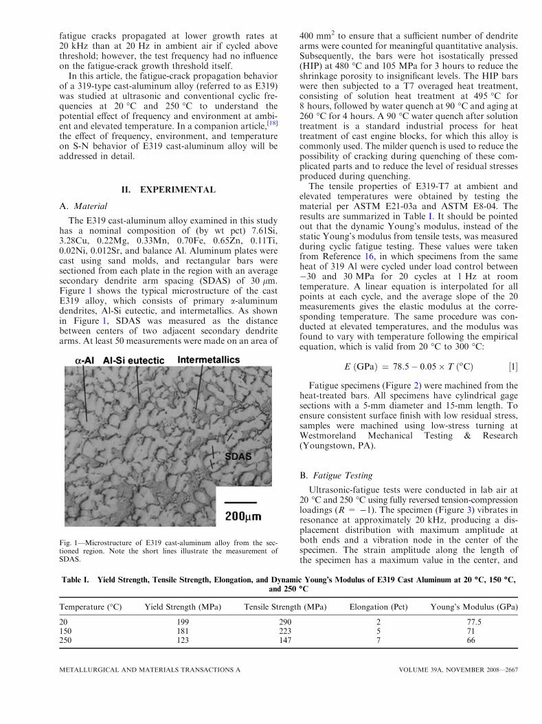
The E319 cast-aluminum alloy examined in this studyhas a nominal composition of (by wt pct) 7.61Si,3.28Cu, 0.22Mg, 0.33Mn, 0.70Fe, 0.65Zn, 0.11Ti,0.02Ni, 0.012Sr, and balance Al. Aluminum plates werecast using sand molds, and rectangular bars weresectioned from each plate in the region with an averagesecondary dendrite arm spacing (SDAS) of 30 lm.Figure 1 shows the typical microstructure of the castE319 alloy, which consists of primary a-aluminumdendrites, Al-Si eutectic, and intermetallics. As shownin Figure 1, SDAS was measured as the distancebetween centers of two adjacent secondary dendritearms. At least 50 measurements were made on an area of
400 mm2 to ensure that a sufficient number of dendritearms were counted for meaningful quantitative analysis.Subsequently, the bars were hot isostatically pressed(HIP) at 480 �C and 105 MPa for 3 hours to reduce theshrinkage porosity to insignificant levels. The HIP barswere then subjected to a T7 overaged heat treatment,consisting of solution heat treatment at 495 �C for8 hours, followed by water quench at 90 �C and aging at260 �C for 4 hours. A 90 �C water quench after solutiontreatment is a standard industrial process for heattreatment of cast engine blocks, for which this alloy iscommonly used. The milder quench is used to reduce thepossibility of cracking during quenching of these com-plicated parts and to reduce the level of residual stressesproduced during quenching.The tensile properties of E319-T7 at ambient and
elevated temperatures were obtained by testing thematerial per ASTM E21-03a and ASTM E8-04. Theresults are summarized in Table I. It should be pointedout that the dynamic Young’s modulus, instead of thestatic Young’s modulus from tensile tests, was measuredduring cyclic fatigue testing. These values were takenfrom Reference 16, in which specimens from the sameheat of 319 Al were cycled under load control between-30 and 30 MPa for 20 cycles at 1 Hz at roomtemperature. A linear equation is interpolated for allpoints at each cycle, and the average slope of the 20measurements gives the elastic modulus at the corre-sponding temperature. The same procedure was con-ducted at elevated temperatures, and the modulus wasfound to vary with temperature following the empiricalequation, which is valid from 20 �C to 300 �C:
E GPað Þ ¼ 78:5� 0:05� T oCð Þ ½1�
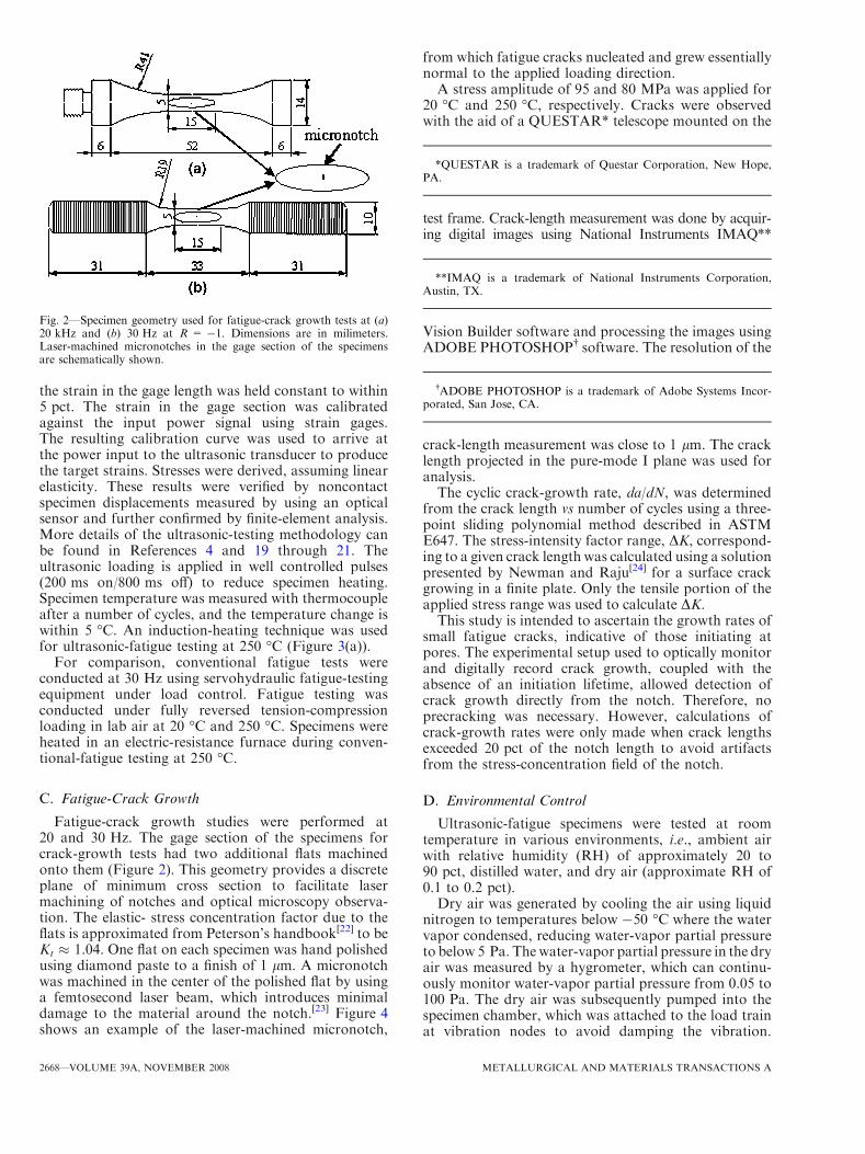
Fatigue specimens (Figure 2) were machined from theheat-treated bars. All specimens have cylindrical gagesections with a 5-mm diameter and 15-mm length. Toensure consistent surface finish with low residual stress,samples were machined using low-stress turning atWestmoreland Mechanical Testing & Research(Youngstown, PA).
B. Fatigue Testing
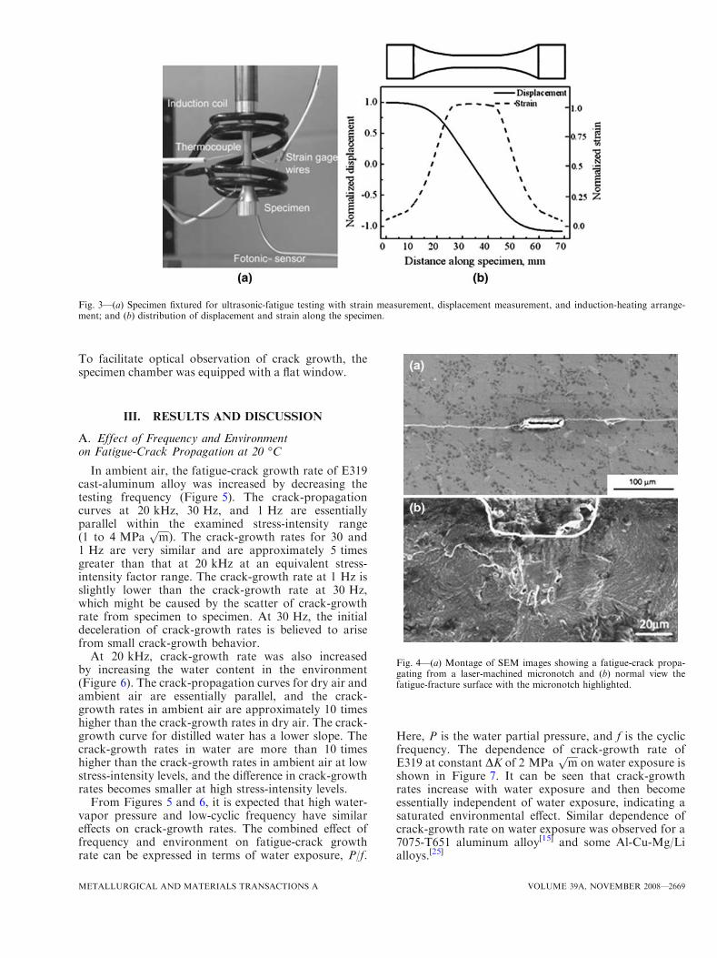
Ultrasonic-fatigue tests were conducted in lab air at20 �C and 250 �C using fully reversed tension-compressionloadings (R = -1). The specimen (Figure 3) vibrates inresonance at approximately 20 kHz, producing a dis-placement distribution with maximum amplitude atboth ends and a vibration node in the center of thespecimen. The strain amplitude along the length ofthe specimen has a maximum value in the center, and
Fig. 1—Microstructure of E319 cast-aluminum alloy from the sec-tioned region. Note the short lines illustrate the measurement ofSDAS.
Table I. Yield Strength, Tensile Strength, Elongation, and Dynamic Young’s Modulus of E319 Cast Aluminum at 20 �C, 150 �C,and 250 �C
Temperature (�C) Yield Strength (MPa) Tensile Strength (MPa) Elongation (Pct) Young’s Modulus (GPa)
20 199 290 2 77.5150 181 223 5 71250 123 147 7 66
METALLURGICAL AND MATERIALS TRANSACTIONS A VOLUME 39A, NOVEMBER 2008—2667
the strain in the gage length was held constant to within5 pct. The strain in the gage section was calibratedagainst the input power signal using strain gages.The resulting calibration curve was used to arrive atthe power input to the ultrasonic transducer to producethe target strains. Stresses were derived, assuming linearelasticity. These results were verified by noncontactspecimen displacements measured by using an opticalsensor and further confirmed by finite-element analysis.More details of the ultrasonic-testing methodology canbe found in References 4 and 19 through 21. Theultrasonic loading is applied in well controlled pulses(200 ms on/800 ms off) to reduce specimen heating.Specimen temperature was measured with thermocoupleafter a number of cycles, and the temperature change iswithin 5 �C. An induction-heating technique was usedfor ultrasonic-fatigue testing at 250 �C (Figure 3(a)).
For comparison, conventional fatigue tests wereconducted at 30 Hz using servohydraulic fatigue-testingequipment under load control. Fatigue testing wasconducted under fully reversed tension-compressionloading in lab air at 20 �C and 250 �C. Specimens wereheated in an electric-resistance furnace during conven-tional-fatigue testing at 250 �C.
C. Fatigue-Crack Growth
Fatigue-crack growth studies were performed at20 and 30 Hz. The gage section of the specimens forcrack-growth tests had two additional flats machinedonto them (Figure 2). This geometry provides a discreteplane of minimum cross section to facilitate lasermachining of notches and optical microscopy observa-tion. The elastic- stress concentration factor due to theflats is approximated from Peterson’s handbook[22] to beKt � 1.04. One flat on each specimen was hand polishedusing diamond paste to a finish of 1 lm. A micronotchwas machined in the center of the polished flat by usinga femtosecond laser beam, which introduces minimaldamage to the material around the notch.[23] Figure 4shows an example of the laser-machined micronotch,
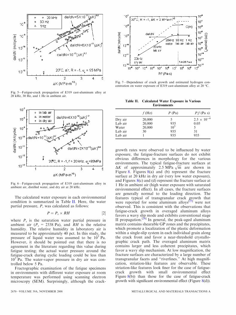
from which fatigue cracks nucleated and grew essentiallynormal to the applied loading direction.A stress amplitude of 95 and 80 MPa was applied for
20 �C and 250 �C, respectively. Cracks were observedwith the aid of a QUESTAR* telescope mounted on the
test frame. Crack-length measurement was done by acquir-ing digital images using National Instruments IMAQ**
Vision Builder software and processing the images usingADOBE PHOTOSHOP� software. The resolution of the
crack-length measurement was close to 1 lm. The cracklength projected in the pure-mode I plane was used foranalysis.The cyclic crack-growth rate, da/dN, was determined
from the crack length vs number of cycles using a three-point sliding polynomial method described in ASTME647. The stress-intensity factor range, DK, correspond-ing to a given crack length was calculated using a solutionpresented by Newman and Raju[24] for a surface crackgrowing in a finite plate. Only the tensile portion of theapplied stress range was used to calculate DK.This study is intended to ascertain the growth rates of
small fatigue cracks, indicative of those initiating atpores. The experimental setup used to optically monitorand digitally record crack growth, coupled with theabsence of an initiation lifetime, allowed detection ofcrack growth directly from the notch. Therefore, noprecracking was necessary. However, calculations ofcrack-growth rates were only made when crack lengthsexceeded 20 pct of the notch length to avoid artifactsfrom the stress-concentration field of the notch.
D. Environmental Control
Ultrasonic-fatigue specimens were tested at roomtemperature in various environments, i.e., ambient airwith relative humidity (RH) of approximately 20 to90 pct, distilled water, and dry air (approximate RH of0.1 to 0.2 pct).Dry air was generated by cooling the air using liquid
nitrogen to temperatures below -50 �C where the watervapor condensed, reducing water-vapor partial pressureto below 5 Pa. Thewater-vapor partial pressure in the dryair was measured by a hygrometer, which can continu-ously monitor water-vapor partial pressure from 0.05 to100 Pa. The dry air was subsequently pumped into thespecimen chamber, which was attached to the load trainat vibration nodes to avoid damping the vibration.
Fig. 2—Specimen geometry used for fatigue-crack growth tests at (a)20 kHz and (b) 30 Hz at R = -1. Dimensions are in milimeters.Laser-machined micronotches in the gage section of the specimensare schematically shown.
*QUESTAR is a trademark of Questar Corporation, New Hope,PA.
**IMAQ is a trademark of National Instruments Corporation,Austin, TX.
�ADOBE PHOTOSHOP is a trademark of Adobe Systems Incor-porated, San Jose, CA.
2668—VOLUME 39A, NOVEMBER 2008 METALLURGICAL AND MATERIALS TRANSACTIONS A
To facilitate optical observation of crack growth, thespecimen chamber was equipped with a flat window.
III. RESULTS AND DISCUSSION
A. Effect of Frequency and Environmenton Fatigue-Crack Propagation at 20 �C
In ambient air, the fatigue-crack growth rate of E319cast-aluminum alloy was increased by decreasing thetesting frequency (Figure 5). The crack-propagationcurves at 20 kHz, 30 Hz, and 1 Hz are essentiallyparallel within the examined stress-intensity range(1 to 4 MPa
ffiffiffiffi
mp
). The crack-growth rates for 30 and1 Hz are very similar and are approximately 5 timesgreater than that at 20 kHz at an equivalent stress-intensity factor range. The crack-growth rate at 1 Hz isslightly lower than the crack-growth rate at 30 Hz,which might be caused by the scatter of crack-growthrate from specimen to specimen. At 30 Hz, the initialdeceleration of crack-growth rates is believed to arisefrom small crack-growth behavior.
At 20 kHz, crack-growth rate was also increasedby increasing the water content in the environment(Figure 6). The crack-propagation curves for dry air andambient air are essentially parallel, and the crack-growth rates in ambient air are approximately 10 timeshigher than the crack-growth rates in dry air. The crack-growth curve for distilled water has a lower slope. Thecrack-growth rates in water are more than 10 timeshigher than the crack-growth rates in ambient air at lowstress-intensity levels, and the difference in crack-growthrates becomes smaller at high stress-intensity levels.
From Figures 5 and 6, it is expected that high water-vapor pressure and low-cyclic frequency have similareffects on crack-growth rates. The combined effect offrequency and environment on fatigue-crack growthrate can be expressed in terms of water exposure, P/f.
Here, P is the water partial pressure, and f is the cyclicfrequency. The dependence of crack-growth rate ofE319 at constant DK of 2 MPa
ffiffiffiffi
mp
on water exposure isshown in Figure 7. It can be seen that crack-growthrates increase with water exposure and then becomeessentially independent of water exposure, indicating asaturated environmental effect. Similar dependence ofcrack-growth rate on water exposure was observed for a7075-T651 aluminum alloy[15] and some Al-Cu-Mg/Lialloys.[25]
Fig. 3—(a) Specimen fixtured for ultrasonic-fatigue testing with strain measurement, displacement measurement, and induction-heating arrange-ment; and (b) distribution of displacement and strain along the specimen.
Fig. 4—(a) Montage of SEM images showing a fatigue-crack propa-gating from a laser-machined micronotch and (b) normal view thefatigue-fracture surface with the micronotch highlighted.
METALLURGICAL AND MATERIALS TRANSACTIONS A VOLUME 39A, NOVEMBER 2008—2669
The calculated water exposure in each environmentalcondition is summarized in Table II. Here, the waterpartial pressure, P, was calculated as follows:
P ¼ Ps � RH ½2�
where Ps is the saturation water partial pressure inambient air (Ps = 2338 Pa), and RH is the relativehumidity. The relative humidity in laboratory air ismeasured to be approximately 40 pct. In this study, thepressure of liquid water was assumed to be 105 Pa.However, it should be pointed out that there is noagreement in the literature regarding this value duringfatigue testing; the actual water pressure around thefatigue-crack during cyclic loading could be less than105 Pa. The water-vapor pressure in dry air was con-trolled below 5 Pa.
Fractographic examination of the fatigue specimensin environments with different water exposure at roomtemperature was performed using scanning electronmicroscopy (SEM). Surprisingly, although the crack-
growth rates were observed to be influenced by waterexposure, the fatigue-fracture surfaces do not exhibitobvious differences in morphology for the variousenvironments. The typical fatigue-fracture surfaces atDK of approximately 2.5 MPa
ffiffiffiffi
mp
are shown inFigure 8. Figures 8(a) and (b) represent the fracturesurface at 20 kHz in dry air (very low water exposure),and Figures 8(c) and (d) represent the fracture surface at1 Hz in ambient air (high water exposure with saturatedenvironmental effect). In all cases, the fracture surfacesare generally normal to the loading direction. Thefeatures typical of transgranular crack growth thatwere reported for some aluminum alloys[25] were notobserved. This is consistent with the observations thatfatigue-crack growth in overaged aluminum alloysfavors a wavy slip mode and exhibits conventional stageII propagation.[26] In general, the peak-aged aluminummatrix contains shearable GP zones and the precipitates,which promote a localization of the plastic deformationwithin a single-slip system in each individual grain alongthe crack front and favor a near-threshold crystallo-graphic crack path. The overaged aluminum matrixcontains larger and less coherent precipitates, whichfavor a wavy slip mechanism. At low magnification, thefracture surfaces are characterized by a large number oftransgranular facets and ‘‘riverlines.’’ At high magnifi-cation, striation-like features are observable. Thesestriation-like features look finer for the case of fatigue-crack growth with small environmental effectFigure 8(b)) than those for the case of fatigue-crackgrowth with significant environmental effect (Figure 8(d)).
Fig. 5—Fatigue-crack propagation of E319 cast-aluminum alloy at20 kHz, 30 Hz, and 1 Hz in ambient air.
Fig. 7—Dependence of crack growth and estimated hydrogen con-centration on water exposure of E319 cast-aluminum alloy at 20 �C.
Fig. 6—Fatigue-crack propagation of E319 cast-aluminum alloy inambient air, distilled water, and dry air at 20 kHz.
Table II. Calculated Water Exposure in Various
Environments
f (Hz) P (Pa) P/f (Pa s)
Dry air 20,000 5 2.5 9 10-4
Lab air 20,000 935 0.05Water 20,000 105 5Lab air 30 935 31Lab air 1 935 935
2670—VOLUME 39A, NOVEMBER 2008 METALLURGICAL AND MATERIALS TRANSACTIONS A
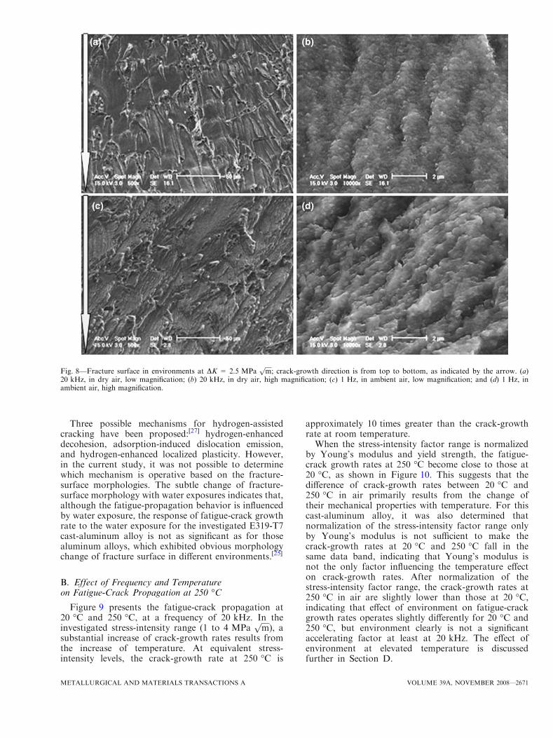
Three possible mechanisms for hydrogen-assistedcracking have been proposed:[27] hydrogen-enhanceddecohesion, adsorption-induced dislocation emission,and hydrogen-enhanced localized plasticity. However,in the current study, it was not possible to determinewhich mechanism is operative based on the fracture-surface morphologies. The subtle change of fracture-surface morphology with water exposures indicates that,although the fatigue-propagation behavior is influencedby water exposure, the response of fatigue-crack growthrate to the water exposure for the investigated E319-T7cast-aluminum alloy is not as significant as for thosealuminum alloys, which exhibited obvious morphologychange of fracture surface in different environments.[25]
B. Effect of Frequency and Temperatureon Fatigue-Crack Propagation at 250 �C
Figure 9 presents the fatigue-crack propagation at20 �C and 250 �C, at a frequency of 20 kHz. In theinvestigated stress-intensity range (1 to 4 MPa
ffiffiffiffi
mp
), asubstantial increase of crack-growth rates results fromthe increase of temperature. At equivalent stress-intensity levels, the crack-growth rate at 250 �C is
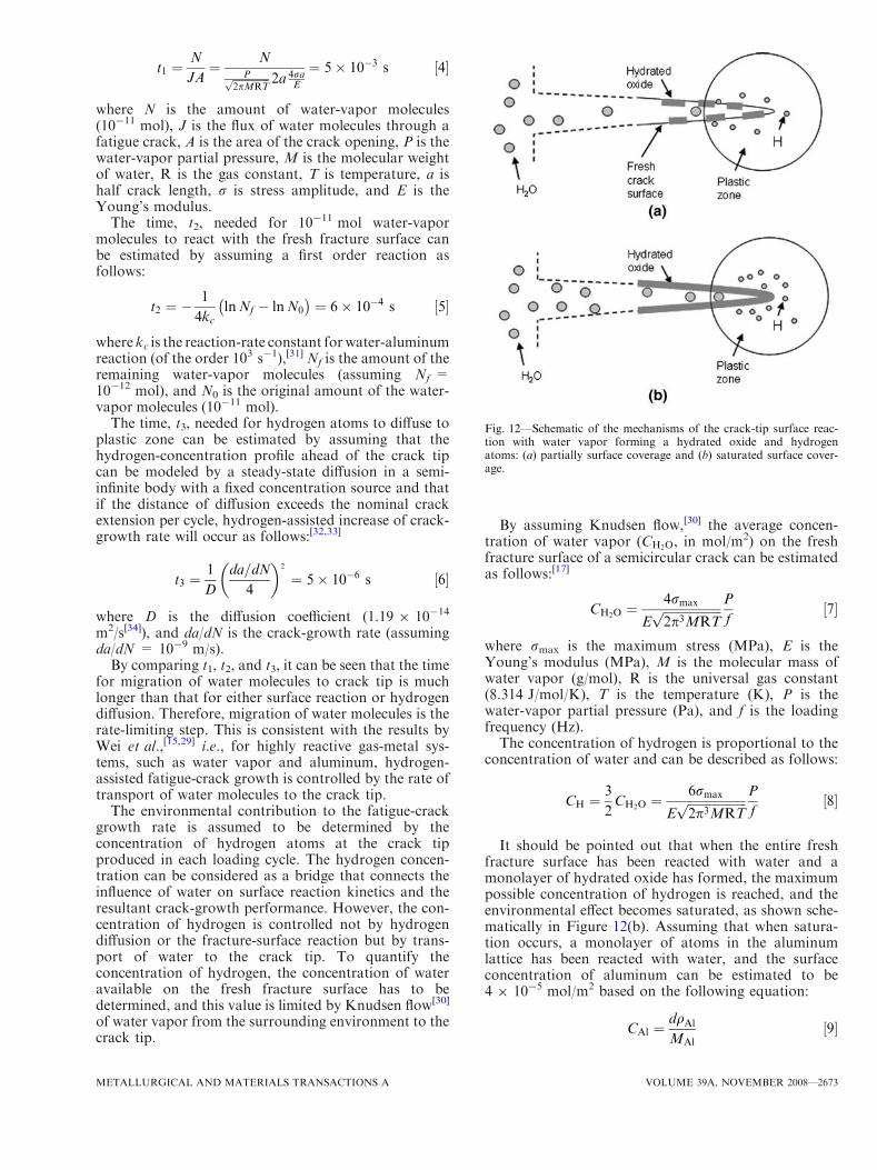
approximately 10 times greater than the crack-growthrate at room temperature.When the stress-intensity factor range is normalized
by Young’s modulus and yield strength, the fatigue-crack growth rates at 250 �C become close to those at20 �C, as shown in Figure 10. This suggests that thedifference of crack-growth rates between 20 �C and250 �C in air primarily results from the change oftheir mechanical properties with temperature. For thiscast-aluminum alloy, it was also determined thatnormalization of the stress-intensity factor range onlyby Young’s modulus is not sufficient to make thecrack-growth rates at 20 �C and 250 �C fall in thesame data band, indicating that Young’s modulus isnot the only factor influencing the temperature effecton crack-growth rates. After normalization of thestress-intensity factor range, the crack-growth rates at250 �C in air are slightly lower than those at 20 �C,indicating that effect of environment on fatigue-crackgrowth rates operates slightly differently for 20 �C and250 �C, but environment clearly is not a significantaccelerating factor at least at 20 kHz. The effect ofenvironment at elevated temperature is discussedfurther in Section D.
Fig. 8—Fracture surface in environments at DK = 2.5 MPaffiffiffiffi
mp
; crack-growth direction is from top to bottom, as indicated by the arrow. (a)20 kHz, in dry air, low magnification; (b) 20 kHz, in dry air, high magnification; (c) 1 Hz, in ambient air, low magnification; and (d) 1 Hz, inambient air, high magnification.
METALLURGICAL AND MATERIALS TRANSACTIONS A VOLUME 39A, NOVEMBER 2008—2671
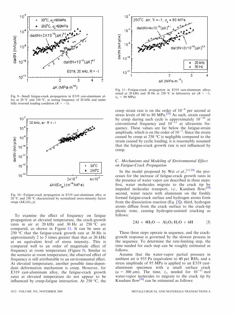
To examine the effect of frequency on fatiguepropagation at elevated temperature, the crack-growthrates in air at 20 kHz and 30 Hz at 250 �C arecompared, as shown in Figure 11. It can be seen at250 �C that the fatigue-crack growth rate at 30 Hz isapproximately 2 to 5 times greater than that at 20 kHzat an equivalent level of stress intensity. This iscompared well to an order of magnitude effect offrequency at room temperature (Figure 5). Similar tothe scenario at room temperature, the observed effect offrequency is still attributable to an environmental effect.At elevated temperature, another possible time-depen-dant deformation mechanism is creep. However, forE319 cast-aluminum alloy, the fatigue-crack growthrates at elevated temperature do not appear to beinfluenced by creep-fatigue interaction. At 250 �C, the
creep strain rate is on the order of 10-8 per second atstress levels of 60 to 80 MPa.[28] As such, strain causedby creep during each cycle is approximately 10-10 atconventional frequency and 10-13 at ultrasonic fre-quency. These values are far below the fatigue-strainamplitude, which is on the order of 10-3. Since the straincaused by creep at 250 �C is negligible compared to thestrain caused by cyclic loading, it is reasonably assumedthat the fatigue-crack growth rate is not influenced bycreep.
C. Mechanisms and Modeling of Environmental Effecton Fatigue-Crack Propagation
In the model proposed by Wei et al.,[15,29] the pro-cesses for the increase of fatigue-crack growth rates inthe presence of water vapor are described in three steps:first, water molecules migrate to the crack tip byimpeded molecular transport, i.e., Kundsen flow;[30]
second, water reacts with aluminum on the freshlyformed fatigue-crack surface and hydrogen atoms formfrom the dissociation reaction (Eq. [3]); third, hydrogenatoms diffuse from the crack surface to the crack-tipplastic zone, causing hydrogen-assisted cracking asfollows:
2Al þ 4H2O! Al2O3�H2O þ 6H ½3�
These three steps operate in sequence, and the crack-growth response is governed by the slowest process inthe sequence. To determine the rate-limiting step, thetime needed for each step can be roughly estimated asfollows.Assume that the water-vapor partial pressure in
ambient air is 935 Pa (equivalent to 40 pct RH), and astress amplitude of 95 MPa is applied to an E319 cast-aluminum specimen with a small surface crack(a = 300 lm). The time, t1, needed for 10-11 molwater-vapor molecules to migrate to the crack tip byKnudsen flow[30] can be estimated as follows:
Fig. 9—Small fatigue-crack propagation in E319 cast-aluminum al-loy at 20 �C and 250 �C, at testing frequency of 20 kHz and underfully reversed loading condition (R = -1).
Fig. 10—Fatigue-crack propagation in E319 cast-aluminum alloy at20 �C and 250 �C characterized by normalized stress-intensity factorrange (DK/(Erys)).
Fig. 11—Fatigue-crack propagation in E319 cast-aluminum alloystested at 20 kHz and 30 Hz at 250 �C in laboratory air (R = -1,ra = 80 MPa).
2672—VOLUME 39A, NOVEMBER 2008 METALLURGICAL AND MATERIALS TRANSACTIONS A
t1 ¼N
JA¼ N
Pffiffiffiffiffiffiffiffiffiffiffiffi
2pMRTp 2a 4ra
E
¼ 5� 10�3 s ½4�
where N is the amount of water-vapor molecules(10-11 mol), J is the flux of water molecules through afatigue crack, A is the area of the crack opening, P is thewater-vapor partial pressure, M is the molecular weightof water, R is the gas constant, T is temperature, a ishalf crack length, r is stress amplitude, and E is theYoung’s modulus.
The time, t2, needed for 10-11 mol water-vapormolecules to react with the fresh fracture surface canbe estimated by assuming a first order reaction asfollows:
t2 ¼ �1
4kclnNf � lnN0
� �
¼ 6� 10�4 s ½5�
where kc is the reaction-rate constant forwater-aluminumreaction (of the order 103 s-1),[31] Nf is the amount of theremaining water-vapor molecules (assuming Nf =10-12 mol), and N0 is the original amount of the water-vapor molecules (10-11 mol).
The time, t3, needed for hydrogen atoms to diffuse toplastic zone can be estimated by assuming that thehydrogen-concentration profile ahead of the crack tipcan be modeled by a steady-state diffusion in a semi-infinite body with a fixed concentration source and thatif the distance of diffusion exceeds the nominal crackextension per cycle, hydrogen-assisted increase of crack-growth rate will occur as follows:[32,33]
t3 ¼1
D
da=dN
4
� �
2
¼ 5� 10�6 s ½6�
where D is the diffusion coefficient (1.19 9 10-14
m2/s[34]), and da/dN is the crack-growth rate (assumingda/dN = 10-9 m/s).
By comparing t1, t2, and t3, it can be seen that the timefor migration of water molecules to crack tip is muchlonger than that for either surface reaction or hydrogendiffusion. Therefore, migration of water molecules is therate-limiting step. This is consistent with the results byWei et al.,[15,29] i.e., for highly reactive gas-metal sys-tems, such as water vapor and aluminum, hydrogen-assisted fatigue-crack growth is controlled by the rate oftransport of water molecules to the crack tip.
The environmental contribution to the fatigue-crackgrowth rate is assumed to be determined by theconcentration of hydrogen atoms at the crack tipproduced in each loading cycle. The hydrogen concen-tration can be considered as a bridge that connects theinfluence of water on surface reaction kinetics and theresultant crack-growth performance. However, the con-centration of hydrogen is controlled not by hydrogendiffusion or the fracture-surface reaction but by trans-port of water to the crack tip. To quantify theconcentration of hydrogen, the concentration of wateravailable on the fresh fracture surface has to bedetermined, and this value is limited by Knudsen flow[30]
of water vapor from the surrounding environment to thecrack tip.
By assuming Knudsen flow,[30] the average concen-tration of water vapor (CH2O, in mol/m2) on the freshfracture surface of a semicircular crack can be estimatedas follows:[17]
CH2O ¼4rmax
Effiffiffiffiffiffiffiffiffiffiffiffiffiffiffiffiffiffiffi
2p3MRTp P
f½7�
where rmax is the maximum stress (MPa), E is theYoung’s modulus (MPa), M is the molecular mass ofwater vapor (g/mol), R is the universal gas constant(8.314 J/mol/K), T is the temperature (K), P is thewater-vapor partial pressure (Pa), and f is the loadingfrequency (Hz).The concentration of hydrogen is proportional to the
concentration of water and can be described as follows:
CH ¼3
2CH2O ¼
6rmax
Effiffiffiffiffiffiffiffiffiffiffiffiffiffiffiffiffiffiffi
2p3MRTp P
f½8�
It should be pointed out that when the entire freshfracture surface has been reacted with water and amonolayer of hydrated oxide has formed, the maximumpossible concentration of hydrogen is reached, and theenvironmental effect becomes saturated, as shown sche-matically in Figure 12(b). Assuming that when satura-tion occurs, a monolayer of atoms in the aluminumlattice has been reacted with water, and the surfaceconcentration of aluminum can be estimated to be4 9 10-5 mol/m2 based on the following equation:
CAl ¼dqAl
MAl½9�
Fig. 12—Schematic of the mechanisms of the crack-tip surface reac-tion with water vapor forming a hydrated oxide and hydrogenatoms: (a) partially surface coverage and (b) saturated surface cover-age.
METALLURGICAL AND MATERIALS TRANSACTIONS A VOLUME 39A, NOVEMBER 2008—2673
where d is the lattice constant of aluminum(4 9 10-10 m), qAl is the density of aluminum(2.7 9 106 g/m3), and MAl is the atomic weight ofaluminum (27 g/mol). According to Eq. [3], the concen-tration of hydrogen at saturation is proportionallyestimated to be 1.2 9 10-4 mol/m2. Thus, the criticalwater exposure when saturation of hydrogen concen-tration occurs can be estimated as follows:
P
f
� �
s
¼ 1:9 � 10�3ffiffiffiffi
Tp E
rmax½10�
at room temperature, and a stress amplitude of 95 MPa;(P/f)s is estimated to be 26 Pa s for the water-aluminumsystem.
The estimated concentrations of water vapor andhydrogen are plotted as a function of water exposure inFigure 13. It is shown that the concentration of waterand hydrogen increases with water exposure untilP/f = 26 Pa s. Above P/f = 26 Pa s, although theconcentration of water still increases with water expo-sure, the concentration of hydrogen remains at themaximum value, which corresponds to a saturation ofenvironmental effect when the entire fresh fracturesurface has been reacted with water, and a monolayerof hydrated oxide has been formed.
Interestingly, the dependence of fatigue-crack growthrate on water exposure closely follows the assumeddependence of hydrogen concentration on water expo-sure, as shown in Figure 7. The observed saturatedenvironmental effect on crack-growth rate and theestimated saturated concentration of hydrogenoccur at approximately the same water exposure(P/f = 26 Pa s). This correlation strongly supports theassumption that the increase in crack-growth ratecaused by environment is determined by the concentra-tion of hydrogen at the crack tip. Thus, (P/f)s is termedthe saturation water exposure, above which hydrogenconcentration at the crack tip and fatigue-crack growthrate are independent of P/f.
Wei et al.[15,29] proposed the following superpositionmodel to quantify the effect of water exposure on thefatigue-crack growth rate:
For Pf
� �
< Pf
� �
s:
da
dN
� �
tot
¼ da
dN
� �
mech
þ da
dN
� �
env
½11�
da
dN
� �
env
¼ da
dN
� �
sat
� da
dN
� �
mech
�
P=fð ÞP=fð Þs
½12�
For Pf
� �
� Pf
� �
s:
da
dN
� �
tot
¼ da
dN
� �
sat
½13�
Here, (da/dN)tot is the fatigue-crack growth rate in adeleterious environment and can be described as the sumof two independent components, (da/dN)mech and(da/dN)env (da/dN)mech is the fatigue-crack growth ratein an inert environment (called pure-mechanical fatigue-crack growth rate); (da/dN)env is the environmentalcontribution to the fatigue-crack growth rate (calledenvironmental fatigue-crack growth rate). When theenvironmental effect becomes saturated, (da/dN)totreaches the maximum value, (da/dN)sat (saturatedfatigue-crack growth rate). The environmental fatigue-crack growth rate is determined by (da/dN)mech,(da/dN)sat, P/f, and (P/f)s. The values of (da/dN)mech
and (da/dN)sat can be estimated based on the experi-mental observations in Figure 7. At a constant DK of2 MPa
ffiffiffiffi
mp
, (da/dN)mech was assumed to be 10-11
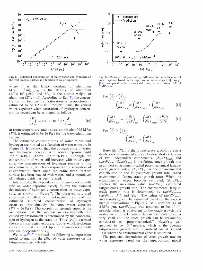
m/cycle, which is equivalent to the crack-growth ratein dry air at 20 kHz, where the environmental effect isvery small and the crack growth can be reasonablyconsidered as ‘‘pure-mechanical.’’ (da/dN)sat wasassumed to be 10-9 m/cycle, which is the averagefatigue-crack growth rate in ambient air at 30 and1 Hz where the environmental effect is saturated.The predicted dependence of crack-growth rate on
water exposure based on the superposition model
Fig. 13—Estimated concentration of water vapor and hydrogen onthe fresh fracture surface as a function of water exposure.
Fig. 14—Predicted fatigue-crack growth response as a function ofwater exposure based on the superposition model (Eqs. [11] through[13]), compared with experimental data, at a constant DK of2 MPa
ffiffiffiffi
mp
.
2674—VOLUME 39A, NOVEMBER 2008 METALLURGICAL AND MATERIALS TRANSACTIONS A
(Eqs. [11] through [13]), with (da/dN)mech = 10-11
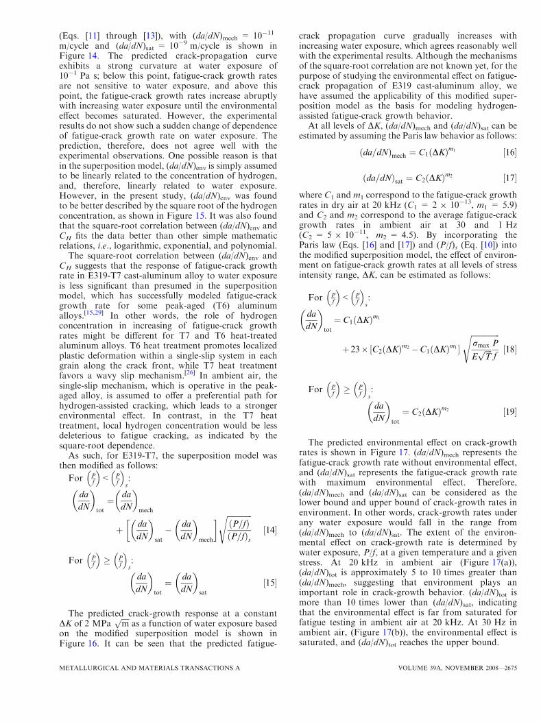
m/cycle and (da/dN)sat = 10-9 m/cycle is shown inFigure 14. The predicted crack-propagation curveexhibits a strong curvature at water exposure of10-1 Pa s; below this point, fatigue-crack growth ratesare not sensitive to water exposure, and above thispoint, the fatigue-crack growth rates increase abruptlywith increasing water exposure until the environmentaleffect becomes saturated. However, the experimentalresults do not show such a sudden change of dependenceof fatigue-crack growth rate on water exposure. Theprediction, therefore, does not agree well with theexperimental observations. One possible reason is thatin the superposition model, (da/dN)env is simply assumedto be linearly related to the concentration of hydrogen,and, therefore, linearly related to water exposure.However, in the present study, (da/dN)env was foundto be better described by the square root of the hydrogenconcentration, as shown in Figure 15. It was also foundthat the square-root correlation between (da/dN)env andCH fits the data better than other simple mathematicrelations, i.e., logarithmic, exponential, and polynomial.
The square-root correlation between (da/dN)env andCH suggests that the response of fatigue-crack growthrate in E319-T7 cast-aluminum alloy to water exposureis less significant than presumed in the superpositionmodel, which has successfully modeled fatigue-crackgrowth rate for some peak-aged (T6) aluminumalloys.[15,29] In other words, the role of hydrogenconcentration in increasing of fatigue-crack growthrates might be different for T7 and T6 heat-treatedaluminum alloys. T6 heat treatment promotes localizedplastic deformation within a single-slip system in eachgrain along the crack front, while T7 heat treatmentfavors a wavy slip mechanism.[26] In ambient air, thesingle-slip mechanism, which is operative in the peak-aged alloy, is assumed to offer a preferential path forhydrogen-assisted cracking, which leads to a strongerenvironmental effect. In contrast, in the T7 heattreatment, local hydrogen concentration would be lessdeleterious to fatigue cracking, as indicated by thesquare-root dependence.
As such, for E319-T7, the superposition model wasthen modified as follows:
For Pf
� �
< Pf
� �
s:
da
dN
� �
tot
¼ da
dN
� �
mech
þ da
dN
� �
sat
� da
dN
� �
mech
�
ffiffiffiffiffiffiffiffiffiffiffiffiffi
P=fð ÞP=fð Þs
s
½14�
For Pf
� �
� Pf
� �
s:
da
dN
� �
tot
¼ da
dN
� �
sat
½15�
The predicted crack-growth response at a constantDK of 2 MPa
ffiffiffiffi
mp
as a function of water exposure basedon the modified superposition model is shown inFigure 16. It can be seen that the predicted fatigue-
crack propagation curve gradually increases withincreasing water exposure, which agrees reasonably wellwith the experimental results. Although the mechanismsof the square-root correlation are not known yet, for thepurpose of studying the environmental effect on fatigue-crack propagation of E319 cast-aluminum alloy, wehave assumed the applicability of this modified super-position model as the basis for modeling hydrogen-assisted fatigue-crack growth behavior.At all levels of DK, (da/dN)mech and (da/dN)sat can be
estimated by assuming the Paris law behavior as follows:
da=dNð Þmech ¼ C1 DKð Þm1 ½16�
da=dNð Þsat ¼ C2 DKð Þm2 ½17�
where C1 and m1 correspond to the fatigue-crack growthrates in dry air at 20 kHz (C1 = 2 9 10-13, m1 = 5.9)and C2 and m2 correspond to the average fatigue-crackgrowth rates in ambient air at 30 and 1 Hz(C2 = 5 9 10-11, m2 = 4.5). By incorporating theParis law (Eqs. [16] and [17]) and (P/f)s (Eq. [10]) intothe modified superposition model, the effect of environ-ment on fatigue-crack growth rates at all levels of stressintensity range, DK, can be estimated as follows:
For Pf
� �
< Pf
� �
s:
da
dN
� �
tot
¼ C1 DKð Þm1
þ 23� C2 DKð Þm2 �C1 DKð Þm1½ �ffiffiffiffiffiffiffiffiffiffiffiffiffiffiffi
rmax
Effiffiffiffi
Tp P
f
s
½18�
For Pf
� �
� Pf
� �
s:
da
dN
� �
tot
¼ C2 DKð Þm2 ½19�
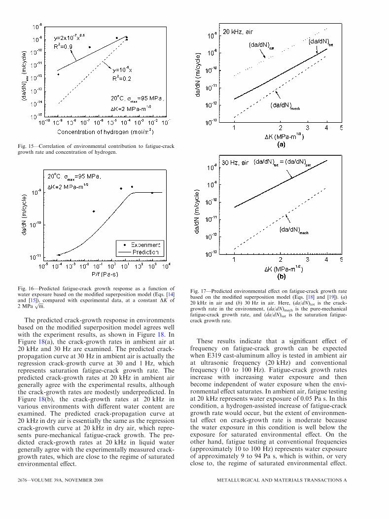
The predicted environmental effect on crack-growthrates is shown in Figure 17. (da/dN)mech represents thefatigue-crack growth rate without environmental effect,and (da/dN)sat represents the fatigue-crack growth ratewith maximum environmental effect. Therefore,(da/dN)mech and (da/dN)sat can be considered as thelower bound and upper bound of crack-growth rates inenvironment. In other words, crack-growth rates underany water exposure would fall in the range from(da/dN)mech to (da/dN)sat. The extent of the environ-mental effect on crack-growth rate is determined bywater exposure, P/f, at a given temperature and a givenstress. At 20 kHz in ambient air (Figure 17(a)),(da/dN)tot is approximately 5 to 10 times greater than(da/dN)mech, suggesting that environment plays animportant role in crack-growth behavior. (da/dN)tot ismore than 10 times lower than (da/dN)sat, indicatingthat the environmental effect is far from saturated forfatigue testing in ambient air at 20 kHz. At 30 Hz inambient air, (Figure 17(b)), the environmental effect issaturated, and (da/dN)tot reaches the upper bound.
METALLURGICAL AND MATERIALS TRANSACTIONS A VOLUME 39A, NOVEMBER 2008—2675
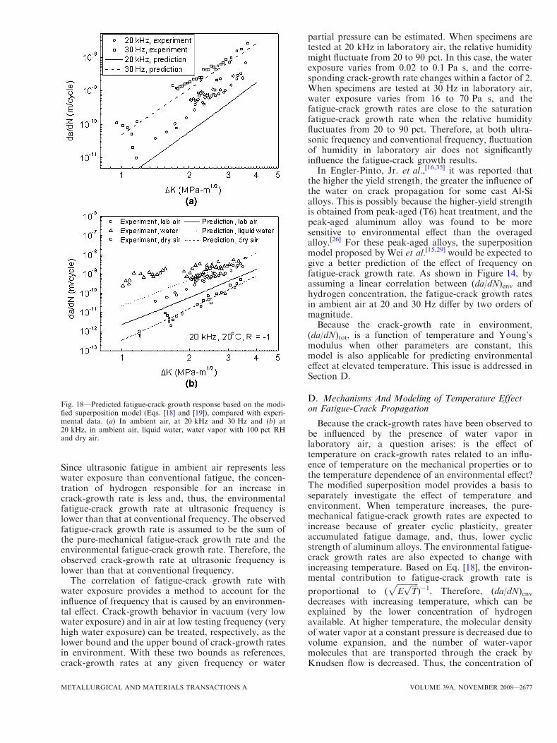
The predicted crack-growth response in environmentsbased on the modified superposition model agrees wellwith the experiment results, as shown in Figure 18. InFigure 18(a), the crack-growth rates in ambient air at20 kHz and 30 Hz are examined. The predicted crack-propagation curve at 30 Hz in ambient air is actually theregression crack-growth curve at 30 and 1 Hz, whichrepresents saturation fatigue-crack growth rate. Thepredicted crack-growth rates at 20 kHz in ambient airgenerally agree with the experimental results, althoughthe crack-growth rates are modestly underpredicted. InFigure 18(b), the crack-growth rates at 20 kHz invarious environments with different water content areexamined. The predicted crack-propagation curve at20 kHz in dry air is essentially the same as the regressioncrack-growth curve at 20 kHz in dry air, which repre-sents pure-mechanical fatigue-crack growth. The pre-dicted crack-growth rates at 20 kHz in liquid watergenerally agree with the experimentally measured crack-growth rates, which are close to the regime of saturatedenvironmental effect.
These results indicate that a significant effect offrequency on fatigue-crack growth can be expectedwhen E319 cast-aluminum alloy is tested in ambient airat ultrasonic frequency (20 kHz) and conventionalfrequency (10 to 100 Hz). Fatigue-crack growth ratesincrease with increasing water exposure and thenbecome independent of water exposure when the envi-ronmental effect saturates. In ambient air, fatigue testingat 20 kHz represents water exposure of 0.05 Pa s. In thiscondition, a hydrogen-assisted increase of fatigue-crackgrowth rate would occur, but the extent of environmen-tal effect on crack-growth rate is moderate becausethe water exposure in this condition is well below theexposure for saturated environmental effect. On theother hand, fatigue testing at conventional frequencies(approximately 10 to 100 Hz) represents water exposureof approximately 9 to 94 Pa s, which is within, or veryclose to, the regime of saturated environmental effect.
Fig. 15—Correlation of environmental contribution to fatigue-crackgrowth rate and concentration of hydrogen.
Fig. 16—Predicted fatigue-crack growth response as a function ofwater exposure based on the modified superposition model (Eqs. [14]and [15]), compared with experimental data, at a constant DK of2 MPa
ffiffiffiffi
mp
.
Fig. 17—Predicted environmental effect on fatigue-crack growth ratebased on the modified superposition model (Eqs. [18] and [19]). (a)20 kHz in air and (b) 30 Hz in air. Here, (da/dN)tot is the crack-growth rate in the environment, (da/dN)mech is the pure-mechanicalfatigue-crack growth rate, and (da/dN)sat is the saturation fatigue-crack growth rate.
2676—VOLUME 39A, NOVEMBER 2008 METALLURGICAL AND MATERIALS TRANSACTIONS A
Since ultrasonic fatigue in ambient air represents lesswater exposure than conventional fatigue, the concen-tration of hydrogen responsible for an increase incrack-growth rate is less and, thus, the environmentalfatigue-crack growth rate at ultrasonic frequency islower than that at conventional frequency. The observedfatigue-crack growth rate is assumed to be the sum ofthe pure-mechanical fatigue-crack growth rate and theenvironmental fatigue-crack growth rate. Therefore, theobserved crack-growth rate at ultrasonic frequency islower than that at conventional frequency.
The correlation of fatigue-crack growth rate withwater exposure provides a method to account for theinfluence of frequency that is caused by an environmen-tal effect. Crack-growth behavior in vacuum (very lowwater exposure) and in air at low testing frequency (veryhigh water exposure) can be treated, respectively, as thelower bound and the upper bound of crack-growth ratesin environment. With these two bounds as references,crack-growth rates at any given frequency or water
partial pressure can be estimated. When specimens aretested at 20 kHz in laboratory air, the relative humiditymight fluctuate from 20 to 90 pct. In this case, the waterexposure varies from 0.02 to 0.1 Pa s, and the corre-sponding crack-growth rate changes within a factor of 2.When specimens are tested at 30 Hz in laboratory air,water exposure varies from 16 to 70 Pa s, and thefatigue-crack growth rates are close to the saturationfatigue-crack growth rate when the relative humidityfluctuates from 20 to 90 pct. Therefore, at both ultra-sonic frequency and conventional frequency, fluctuationof humidity in laboratory air does not significantlyinfluence the fatigue-crack growth results.In Engler-Pinto, Jr. et al.,[16,35] it was reported that
the higher the yield strength, the greater the influence ofthe water on crack propagation for some cast Al-Sialloys. This is possibly because the higher-yield strengthis obtained from peak-aged (T6) heat treatment, and thepeak-aged aluminum alloy was found to be moresensitive to environmental effect than the overagedalloy.[26] For these peak-aged alloys, the superpositionmodel proposed by Wei et al.[15,29] would be expected togive a better prediction of the effect of frequency onfatigue-crack growth rate. As shown in Figure 14, byassuming a linear correlation between (da/dN)env andhydrogen concentration, the fatigue-crack growth ratesin ambient air at 20 and 30 Hz differ by two orders ofmagnitude.Because the crack-growth rate in environment,
(da/dN)tot, is a function of temperature and Young’smodulus when other parameters are constant, thismodel is also applicable for predicting environmentaleffect at elevated temperature. This issue is addressed inSection D.
D. Mechanisms And Modeling of Temperature Effecton Fatigue-Crack Propagation
Because the crack-growth rates have been observed tobe influenced by the presence of water vapor inlaboratory air, a question arises: is the effect oftemperature on crack-growth rates related to an influ-ence of temperature on the mechanical properties or tothe temperature dependence of an environmental effect?The modified superposition model provides a basis toseparately investigate the effect of temperature andenvironment. When temperature increases, the pure-mechanical fatigue-crack growth rates are expected toincrease because of greater cyclic plasticity, greateraccumulated fatigue damage, and, thus, lower cyclicstrength of aluminum alloys. The environmental fatigue-crack growth rates are also expected to change withincreasing temperature. Based on Eq. [18], the environ-mental contribution to fatigue-crack growth rate is
proportional to (ffiffiffiffiffiffiffiffiffiffiffi
Effiffiffiffi
Tpp
)-1. Therefore, (da/dN)envdecreases with increasing temperature, which can beexplained by the lower concentration of hydrogenavailable. At higher temperature, the molecular densityof water vapor at a constant pressure is decreased due tovolume expansion, and the number of water-vapormolecules that are transported through the crack byKnudsen flow is decreased. Thus, the concentration of
Fig. 18—Predicted fatigue-crack growth response based on the modi-fied superposition model (Eqs. [18] and [19]), compared with experi-mental data. (a) In ambient air, at 20 kHz and 30 Hz and (b) at20 kHz, in ambient air, liquid water, water vapor with 100 pct RHand dry air.
METALLURGICAL AND MATERIALS TRANSACTIONS A VOLUME 39A, NOVEMBER 2008—2677
water vapor and the concentration of hydrogen pro-duced are decreased. On the other hand, Young’smodulus decreases with increasing temperature, andthis will increase crack-opening displacement and, inturn, make it easier for water molecules to migrate to thecrack tip. Therefore, (da/dN)env is expected to decreasewith increasing temperature, but the decrease is offset bythe simultaneously decreased Young’s modulus.
To investigate the combined influence of temperatureand frequency on crack propagation of E319 cast-aluminum alloy, Eqs. [18] and [19] were modified asfollows to take into account the effect of temperature onfatigue-crack growth behavior:
For Pf
� �
< Pf
� �
s:
da
dN
� �
tot
¼C01DKErys
� �m01
þ23� C02DKErys
� �m02
�C01DKErys
� �m01
" #ffiffiffiffiffiffiffiffiffiffiffiffiffiffi
rmax
Effiffiffiffi
Tp P
f
s
½20�
For Pf
� �
� Pf
� �
s:
da
dN
� �
tot
¼ C0
2
DKErys
� �m02
½21�
where C01 and m01 correspond to (da/dN)mech afternormalization of stress-intensity factor range(C01 ¼ 5� 1029, m01 ¼ 5:9) and C02and m02 correspond to(da/dN)sat after normalization of stress-intensity factor
range (C02 ¼ 8� 1020, m02 ¼ 4:5). (da/dN)tot is then
determined by the termffiffiffiffiffiffiffiffiffiffiffi
rmax
Effiffiffi
Tp P
f
q
. In Eq. [20], the second
term on the right represents (da/dN)env as follows:
da
dN
� �
env
¼ 23� C02DKErys
� �m02
� C01DKErys
� �m01
" #ffiffiffiffiffiffiffiffiffiffiffiffiffiffiffi
rmax
Effiffiffiffi
Tp P
f
s
½22�
It would be helpful if (da/dN)mech and (da/dN)sat at250 �C were known. However, this information is notavailable. So we assume that (da/dN)mech and (da/dN)satobtained at room temperature apply for all temperaturesafter normalization of the stress-intensity factor rangeby Young’s modulus and yield strength; i.e., at equiv-
alent levels of DK/(Erys),dadN
� �250oC
mech¼ da
dN
� �20oC
mech, and
dadN
� �250oC
sat¼ da
dN
� �20oC
sat.
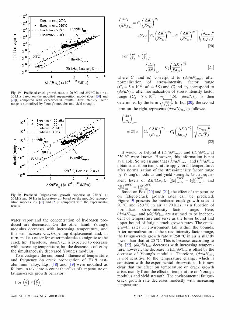
Based on Eqs. [20] and [21], the effect of temperatureon fatigue-crack growth rates can be predicted.Figure 19 presents the predicted crack-growth rates at20 �C and 250 �C in air at 20 kHz, as a function ofnormalized stress-intensity factor range. Here,(da/dN)mech and (da/dN)sat are assumed to be indepen-dent of temperature and serve as the lower bound andupper bound of fatigue-crack growth rates. The crack-growth rates in environment fall within the bounds.After normalization of the stress-intensity factor range,the fatigue-crack growth rate at 250 �C in air is slightlylower than that at 20 �C. This is because, according toEq. [22], (da/dN)env decreases with increasing tempera-ture; however, the decrease in (da/dN)env is offset by thedecrease of Young’s modulus. Therefore, (da/dN)envis not sensitive to the temperature change, which isconsistent with the experimental observations. It is nowclear that the effect on temperature on crack growtharises mainly from the effect of temperature on Young’smodulus and yield strength. The environmental fatigue-crack growth rate decreases modestly with increasingtemperature.
Fig. 19—Predicted crack growth rates at 20 �C and 250 �C in air at20 kHz based on the modified superposition model (Eqs. [20] and[21]), compared with experimental results. Stress-intensity factorrange is normalized by Young’s modulus and yield strength.
Fig. 20—Predicted fatigue-crack growth response at 250 �C at20 kHz and 30 Hz in laboratory air based on the modified superpo-sition model (Eqs. [20] and [21]), compared with the experimentalresults.
2678—VOLUME 39A, NOVEMBER 2008 METALLURGICAL AND MATERIALS TRANSACTIONS A
The effect of frequency on fatigue-crack growth rateat elevated temperature can be modeled using Eqs. [20]and [21]. The effect of frequency at elevated temperatureis still attributable to an environmental effect. Whenother parameters are constant, increasing testing fre-quency will decrease water exposure, and this willdecrease (da/dN)env and, therefore, (da/dN)tot. Thepredicted fatigue-crack growth rates at 250 �C at testingfrequency of 20 kHz and 30 Hz are presented inFigure 20. It can be seen that, at 250 �C, the predictedcrack-growth rates at 20 kHz are approximately anorder of magnitude lower than the predicted crack-growth rates at 30 Hz. At 250 �C, comparison ofexperimental results to the model indicates that thepredicted difference in crack-growth rates between20 kHz and 30 Hz is greater than the experimentalobservations, but the trend of greater crack-growth ratesat lower frequency agrees well with the experimentalresults.
IV. CONCLUSIONS
The fatigue-crack propagation behavior of E319cast-aluminum alloy was determined at both 20 kHzand 30 Hz in air at 20 �C and 250 �C. The majorconclusions are summarized as follows.
1. The crack-growth rate of E319 cast-aluminum alloyin laboratory air at 20 kHz is lower than at 30 Hzat both 20 �C and 250 �C. The difference in fatigue-crack growth rates in air between 20 kHz and30 Hz is attributable to an environmental effect.
2. The presence of water in air was found to increasethe fatigue-crack growth rate. At a given stress-intensity factor range, DK, fatigue-crack growthrate increases with water exposure, P/f, until itreaches the maximum value when saturation of theenvironmental contribution occurs. Fatigue testingat 30 Hz in air represents higher water exposurethan fatigue testing at 20 kHz, and, therefore, thecrack-growth rates at 30 Hz are higher than that at20 kHz. The dependence of crack-growth rate onwater exposure closely follows the dependence ofhydrogen concentration on water exposure, whichsupports the assumption that the enhancement ofcrack-growth rate caused by environment is deter-mined by the concentration of hydrogen in the plas-tic zone.
3. The effect of frequency and environment on fatigue-crack growth rate is characterized by a modifiedsuperposition model. In this model, hydrogen-induced increase of fatigue-crack growth rate isassumed to be proportional to the square root ofhydrogen concentration, which is determined by thetransport rate of water molecules from the sur-rounding environment to the crack tip. Based onthis model, fatigue-crack growth rates over theentire range of DK in various environments withdifferent water exposure can be predicted, and thepredictions generally agree well with the experimen-tal observations.
4. The fatigue-crack growth rate at all temperaturescan be successfully described by a universal versionof the modified superposition model, in whichcrack-growth rate is a function of normalizedstress-intensity factor range, DK/(Erys). This modelprovides a framework to separately characterize theintrinsic effect of temperature on mechanical prop-erties and the effect of environment at elevated tem-perature. The effect of temperature on fatigueresistance primarily results from the intrinsic effectof temperature on Young’s modulus and yieldstrength. The environmental contribution to fati-gue-crack growth rates modestly decreases withincreasing temperature.
5. These results show that environmental effects needto be considered when ultrasonic fatigue is used togenerate fatigue data for modeling the fatigue prop-erty of the aluminum-alloy components that operateunder conventional loading frequency in service. Amodified superposition model was proposed tocharacterize the hydrogen-induced increase of fati-gue-crack growth rates in E319 cast-aluminumalloy. Although based on numerous assumptions,this model provides a basis for investigation of fre-quency effect on fatigue behavior due to environ-mental effect at both room temperature andelevated temperature.
ACKNOWLEDGMENTS
Financial support provided by the United StatesNational Science Foundation (Grant No. DMR0211067) and Ford Motor Company is gratefullyacknowledged. The authors thank C.J. Torbet for hisassistance with environmental control, A. Shyam forhis advice on small crack-growth testing, and J. Yi forhelpful discussions.
REFERENCES1. M.J. Caton, J.W. Jones, J.M. Boileau, and J.E. Allison: Metall.
Mater. Trans. A, 1999, vol. 30A, pp. 3055–68.2. M.J. Couper, A.E. Neeson, and J.R. Griffiths: Fatigue Fract. Eng.
Mater. Struct., 1990, vol. 13 (3), pp. 213–27.3. B. Skallerud, T. Iveland, and G. Harkegard: Eng. Fract. Mech.,
1993, vol. 44 (6), pp. 857–74.4. X. Zhu, A. Shyam, J.W. Jones, H. Mayer, J.V. Lasecki, and J.E.
Allison: Int. J. Fatigue, 2006, vol. 28 (11), pp. 1566–71.5. L.E. Coffin: inUltrasonic Fatigue, J.M. Wells, O. Buck, L.D. Roth,
and J.K. Tien, eds., TMS-AIME, Warrendale, PA, 1982, p. 423.6. C. Laird and P. Charlsey: in Ultrasonic Fatigue, J.M. Wells,
O. Buck, L.D. Roth, and J.K. Tien, eds., TMS-AIME,Warrendale,PA, 1982, p. 183.
7. J.K. Tien: in Ultrasonic Fatigue, J.M. Wells, O. Buck, L.D. Roth,and J.K. Tien, eds., TMS-AIME, Warrendale, PA, 1982, p. 1.
8. B. Holper, H. Mayer, A.K. Vasudevan, and S.E. Stanzl-Tschegg:Int. J. Fatigue, 2003, vol. 25 (5), pp. 397–411.
9. B. Holper, H. Mayer, A.K. Vasudevan, and S.E. Stanzl-Tschegg:Int. J. Fatigue, 2004, vol. 26 (1), pp. 27–38.
10. J. Ruiz and M. Elices: Vacuum, 1994, vol. 45 (10–11), pp. 1069–71.11. S.E. Stanzl, H.R. Mayer, and E.K. Tschegg: Mater. Sci. Eng., A,
1991, vol. 147 (1), pp. 45–54.
METALLURGICAL AND MATERIALS TRANSACTIONS A VOLUME 39A, NOVEMBER 2008—2679
12. M. Papakyriacou, H. Mayer, U. Fuchs, S.E. Stanzl-Tschegg, andR.P. Wei: Fatigue Fract. Eng. Mater. Struct., 2002, vol. 25 (8–9),pp. 795–804.
13. R.S. Piasick and R.P. Gangloff: Metall. Trans. A, 1991, vol. 22A,pp. 2415–28.
14. J. Petit, G. Henaff, and C. Sarrazin-Baudoux: EnvironmentallyAssisted Fatigue in Gaseous Atmosphere, Elsevier Press, Amster-dam, 2003, pp. 211–80.
15. M. Gao, P.S. Pao, and R.P. Wei: Metall. Trans. A, 1988, vol. 19A,pp. 1739–50.
16. C.C. Engler-Pinto, Jr., R.J. Frisch, Sr., J.V. Lasecki, J.E. Allison,X. Zhu, and J.W. Jones: SAE Technical Paper 2006-01-0540, SAEInternational, Warrendale, PA.
17. X. Zhu: Ph.D. Dissertation, University of Michigan, Ann Arbor,MI, 2007.
18. X. Zhu, J.W. Jones, and J.E. Allison: Metall. Mater. Trans. A,2007, vol. 38A, doi:10.1007/s11661-008-9631-1.
19. J. Huang, J.E. Spowart, and J.W. Jones: Fatigue Fract. Eng.Mater. Struct., 2006, vol. 29 (7), pp. 507–17.
20. A.T. Shyam, S.K. Jha, J.M. Larsen, M.J. Caton, C.J. Szczepanski,T.M. Pollock, and J.W. Jones: Superalloys, 2004, Champion, PA,2004.
21. J.Z. Yi, C.J. Torbet, Q. Feng, T.M. Pollock, and J.W. Jones:Mater. Sci. Eng., A, 2007, vol. 443 (1–2), pp. 142–49.
22. R.E. Peterson: Stress Concentration Factors, John Wiley & Sons,New York, NY, 1974, p. 37.
23. Q. Feng, Y.N. Picard, H. Liu, S.M. Yalisove, G. Mourou, andT.M. Pollock: Scripta Mater., 2005, vol. 53 (5), pp. 511–16.
24. J.C. Newman and I.S. Raju: Eng. Fract. Mech., 1981, vol. 15,pp. 185–92.
25. Y.J. Ro, S.R. Agnew, and R.P. Gangloff: VHCF-4, TMS,Warrendale, PA, 2007.
26. J. Petit and C. Sarrazin-Baudoux: Int. J. Fatigue, 2006, vol. 28(11), pp. 1471–78.
27. R.P. Gangloff: Hydrogen-Assisted Cracking, Elsevier Press,Amsterdam, 2003, pp. 31–101.
28. C.C. Engler-Pinto, Jr., J.V. Lasecki, J.M. Boileau, and J.E.Allison: SAE Technical Paper 2004-01-1029.
29. R.P. Wei: Fatigue Fract. Eng. Mater. Struct., 2002, vol. 25 (8–9),pp. 845–54.
30. E.A. Mason and A.P. Malinauskas: Gas Transport in PorousMedia: The Dusty-Gas Model, Elsevier Press, Amsterdam, 1983.
31. R.P. Wei, P.S. Pao, R.G. Hart, T.W. Weir, and G.W. Simmons:Metall. Mater. Trans. A, 1980, vol. 11A, pp. 151–58.
32. A.D.B. Gingell and J.E. King: Acta Mater., 1997, vol. 45 (9),pp. 3855–70.
33. N.J.H. Holroyd and D. Hardie: Corros. Sci., 1983, vol. 23 (6),pp. 527–31.
34. D.J. Fisher: Hydrogen Diffusion in Metals—A 30-Year Retrospec-tive, Scitec Publications Ltd., Uetikon-Zurich, Switzerland, 1999,pp. 30–31.
35. C.C. Engler-Pinto, Jr., R.J. Frisch, Sr., J.V. Lasecki, H. Mayer,and J.E. Allison: VHCF-4, TMS, Warrendale, PA, 2007.
2680—VOLUME 39A, NOVEMBER 2008 METALLURGICAL AND MATERIALS TRANSACTIONS A