Embed Size (px)
Citation preview

Effect of Corrosion-Fatigue Coupled Damage on Mechanical Properties of Q345 Angle Steel
Junjie Wang, Chuntao Zhang and Ruheng Wang School of Civil Engineering and Architecture, Southwest University of Science and Technology, Mianyang, 621010, China
Abstract-Atmospheric environmental corrosion and wind-induced fatigue achieve a long-term synergistic effect, mutual coupling and promotion with each other. Under this circumstance, the speed of structural performance degradation accelerates and the ability of the structure to resist accidental loading decreases. In this paper, an evolutionary model for evaluating fatigue damage is established based on the characteristics of energy dissipation and fatigue crack propagation. Meanwhile, a corrosion damage model is established based on basic mechanical parameters. Then a coupling factor is deduced to evaluate the correlation between corrosion damage and fatigue damage, and the corrosion-fatigue coupled damage model is established by using this coupling factor. Finally, a quasi-static test of Q345 angle steel is conducted to study the failure modes, the hysteresis curve and the variation of main performance evaluation parameters under three test conditions, and a corresponding coupled damage performance degradation model is established.
Keywords—corrosion fatigue; Q345 Angle Steel; coupling factor; coupled damage model
I. INTRODUCTION
In a harsh natural environment, high-rise structural system such as derrick and tower withstand continuous and alternating loads of wind and mechanical vibration while bearing atmospheric corrosion. And environmental corrosion leads to a decrease of the fatigue strength of the material, accelerating the expansion of fatigue cracks. Meanwhile, the acceleration of fatigue cracks propagation further promotes the corrosion. The synergistic effect of atmospheric environmental corrosion and wind-induced fatigue facilitates the degeneration of structure, which reduces the possibility to complete predetermined function during the providing time and conditions. At present, although some scholars have studied the corrosion-fatigue damage of steel, the current research is limited to the material category. Whereas the corrosion-fatigue coupling damage problem is relatively lack of research on the component or structural level. Hence, the effect of corrosion fatigue-coupling damage on hysteresis energy dissipation performance of Q345 angle steel members is studied through theoretical modeling and a quasi-static test.
II. COUPLING DAMAGE MODELING
A. Fatigue Damage Modeling
Material damage is actually an irreversible energy dissipation process. Thus, a damage evolutionary equation,
which is deduced based on the internal variable orthogonal flow rule, is adopted. That is:
11/
1mD AY Y
m
(1)
Where Ψ* is the dissipative potential of Helmholtz free energy, and Y is the damage energy dissipation rate. The value of Ψ* determines the damage evolution model, therefore by adopting the power function of Y, the attenuation form of Ψ* can be determined as :
1
1
1
mAY
m (2)
The undetermined parameters A and m are obtained though fatigue tests of material or components. Where A is the characteristic parameter to measure material damage, and m is the shape parameter reflecting the rate of free energy dissipative potential attenuation. By substituting (2) into (1), we obtain:
/ mD Y AY (3)
Since the internal cause of structural damage is material property and the external cause is fatigue stress amplitude
_
[6], the material(or components) damage evolutionary model is established by adopting Paris formula(Equation (4)), and the model is expressed as (5).
mKCdNda )(/
1
1
)/1(1 mfNND (5)
Where C and m are material constants, a is the crack length and N is the fatigue life span. Equation(5) can be simplified as Miner fatigue cumulative equation when m=0.
International Conference on Mathematics, Modelling, Simulation and Algorithms (MMSA 2018)
Copyright © 2018, the Authors. Published by Atlantis Press. This is an open access article under the CC BY-NC license (http://creativecommons.org/licenses/by-nc/4.0/).
Advances in Intelligent Systems Research, volume 159
146

B. Damage Evaluation Model Based on Ductility
The ratio of stiffness degradation value ΔK to original stiffness K is adopted to measure the degree of degradation and damage on structural deformation[8], given as:
0 0
Δ1 R
K
KKω =
K K (6)
In other words, the damage degree of structure or components can be regarded as a difference between 1 and the ratio of the residual stiffness KR to the initial stiffness K0.The yield stiffness Ky, yield displacement Δy and the limit displacement Δu are obtained though test. The expression of the stiffness degradation value ΔK is determined using Clough two-line degenerate model, which is:
Δ
ΔΔ
γ
yy
u
K K
(7)
The unloading stiffness coefficient γ is determined as:
ΔΔ
lgΔ
y
y u
Kγ
K
(8)
The ratio of Δu to Δy is determined as ductility ratio, thus (8) can be rewritten as:
Δ 1
lgy
Kγ
K μ
(9)
Obviously, the degradation value ΔK can be calculated by substituting γ into (7), then the stiffness damage degree ωK is derived by substituting aforementioned ΔK into (6). Thus, the stiffness damage degree ωi of certain cycle i under reversible loading can be derived through (6), and the stiffness damage degree under n cyclic loading can be expressed as:
1 1 0
Δn ni
ii i
Kω ω=
K
(10)
C. Damage Evaluation Model Based on Bearing Capacity
When the bearing capacity of structure or components is undertaken as a measure of damage degree, as the initial bearing capacity and residual bearing capacity are determined as P0 and PR respectively, the degradation model is:
0
=1-P
P
D. Coupling Modelling
It is vital to establish the variation law of the damage degree ω with the erosion damage t or the fatigue damage d calculated by (10) and (11), and the influence of the two damage conditions is a crucial issue. If θ is assumed to be the coupling factor which measures the interaction between corrosion and fatigue and promotes each other, then the coupling damage formula of the two kinds of damage is:
0
0
0
, = 1- ,
= 1- 1-
= 1- - - ,
, = + +
P t d P t d
P t d
P t d t d t d
t d t d t d
(12)
The coupling factor of two kinds of damage can be calculated through (12) as:
, -
=t d t d
t d
(13)
Therefore, the expression of coupling factors under various damage di(i=1,2,…,n), is determined as:
1 21
1
, ,...,=
n
n ii
n
ii
d d d d
d
(14)
The coupling factor θ of (14) can effectively measure the effects of multiple damage interactions and mutual coupling. When θ=0 , it indicates that all kinds of damage are mutually independent, and the total damage of the components or structure under the combined effect of multiple damage is equal to the sum of the damage caused by the component or the structure separately; When θ<0, it shows that each kind of damage are mutually restraint with each other, and the total damage of the components or structure under the combined effect of multiple damage is less than the sum of the damage caused by the component or the structure separately; When θ>0, it indicates that mutually promotion and intercoupling are among all kinds of damage, and the total damage of the components or structure under the combined effect of multiple damage is more than the sum of the damage caused by the component or the structure separately.
III. TEST OVERVIEW
In this test, the MTS electro-hydraulic servo loading system is used to conduct a low frequency cyclic test on Q345 angle steel components, as shown in Fig.1 and Fig.2. The specimens are corroded by M corrosion method, then fatigue vibration is conducted after corrosion, and test conditions are shown in Table.1. At last, the quasi-static test is carried out by using the
Advances in Intelligent Systems Research, volume 159
147
loading system shown in figure 3.
FIGURE I. THE MTS COMPUTER-ACTUATOR ON-LINE SYSTEM
FIGURE II. SPECIMENS OF Q345 ANGLE STEEL
FIGURE III. THE P-Δ DOUBLE CONTROLSYSTEM
TABLE I. TEST CONDITIONS
Test category
Specimen serial number
Corrosion-fatigue test conditionsSpecimen number
Quasi-static test
Corrosion model Fatigue vibrationM ti/h Smax/MPa N/ cycle
None- damage
L - - - - 2 √
corrosion CL-1 M 12 - - 2 √ CL-2 M 24 - - 2 √ CL-3 M 36 - - 2 √
fatigue LF-1 - - 177.96 4.0×10⁴ 2 √ LF-2 - - 177.96 2.5×10⁴ 2 √ LF-3 - - 177.96 1.0×10⁴ 2 √
Corrosion-fatigue
CLF-1 M 12 177.96 4.0×10⁴ 2 √ CLF-2 M 12 177.96 2.5×10⁴ 2 √ CLF-3 M 12 177.96 1.0×10⁴ 2 √
IV. TEST RESULTS
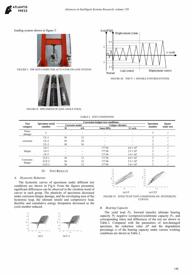
A. Hysteretic Behavior
The hysteretic curves of specimens under different test conditions are shown in Fig.4. From the figures presented, significant differences can be observed in the variation trend of curves in each group. The plasticity of specimens decreased under corrosion-fatigue damage, and the enveloping area of the hysteresis loop, the ultimate tensile and compressive load, ductility and cumulative energy dissipation decreased as the cycle number reduced.
-15 -10 -5 0 5 10 15
-200
-100
0
100
200
300
P/k
N
/mm-15 -10 -5 0 5 10 15
-200
-100
0
100
200
300
P/k
N
/mm
(a) L (a) C L
-3 -2 -1 0 1 2 3
-150
-100
-50
0
50
100
150
200
/mm
P/k
N
-3 -2 -1 0 1 2 3 4
-200
-150
-100
-50
0
50
100
150
200
/mm
P/k
N
(a) LF (a) CLF
FIGURE IV. EFFECTS OF TEST CONDITIONS ON HYSTERETIC CURVES
B. Bearing Capacity
The yield load Py, forward (tensile) ultimate bearing capacity Pt, negative (compressive)ultimate capacity Pc, and corresponding ratios and differences of the test are shown in Table.3. Compared with the parameters of non-damaged specimen, the reduction value ΔP and the degradation percentage ω of the bearing capacity under various working conditions are shown in Table 2.
Advances in Intelligent Systems Research, volume 159
148

TABLE II. BEARING CAPACITY OF Q345 EQUAL-ANGLES WITH DIFFERENT DAMAGE
Test conditions Py(kN) Pt (kN) Pc (kN) ΔPy /kN) ΔPt /kN ΔPc /kN ωy ωt ωc
L 212.746 228.130 201.662 - - - - - - CL1 188.340 199.772 192.457 24.406 28.358 9.205 0.1147 0.1243 0.0456
CL2 184.981 195.273 179.078 27.765 32.857 22.584 01305 0.1440 0.1119
CL3 179.628 190.923 173.088 33.118 37.207 28.574 0.1556 0.1631 0.1417
FL1 135.968 143.333 163.552 76.778 84.797 38.11 0.3609 0.3717 0.1890
FL2 174.428 193.960 191.320 38.318 34.170 10.342 0.1801 0.1498 0.0513
FL3 205.625 213.295 202.795 7.121 14.835 -1.133 0.0335 0.0650 -0.0056
CFL1 111.218 126.722 177.910 101.528 101.408 23.752 0.477 0.445 0.1178
CFL2 151.104 177.002 184.381 61.642 51.128 17.281 0.2897 0.2241 0.0857
CFL3 177.340 197.272 190.708 35.406 30.858 10.954 0.1664 0.1353 0.0543
The bearing capacity degenerated with the decease of the
net sectional area of specimens, and the tensile and compressive capacity of the specimens decreased by 16.31% and 13.61% respectively when corrosion time reach to 36h. Meanwhile, the yield load was also reduced by 15.57%. The yield load and the maximum tensile and compressive capacity have changed significantly under fatigue damage condition. When fatigue damage d increased from 0.167 to 0.669, the yield load and the maximum tensile and compression capacity were reduced by 32.74%, 30.67% and 19.46%; The degradation of bearing capacity is more obvious when fatigue damage increased, whereas the degradation speed of Pc decreased when the ratio of Pc to Py increased.
According to the bearing capacity variation rule of specimens in corrosion group and fatigue group, the degradation model of damage degree ω with corrosion time t and fatigue damage d is established as:
49.591 0.65275
+49.591 0.65275 49.591 0.65275
, 0.19403 +0.21229 -0.39463
+ 0.04119 -0.04467 -0.0349 +0.03785
t d
y
t d t N
y
t d e e
e e e
(15a)
72.182 0.41773
+72.182 0.41773 72.182 0.41773
, 0.35639 +0.09035 -0.43411
+ 0.036858 -0.03395 -0.035044 +0.032279
t d
t
t d t d
t
t d e e
e e e
(15b)
54.587 0.16168
+54.587 0.16168 54.587 0.16168
, 0.13354 +0.00296 0.16238
+ 5.21 38.55 -5.21 +38.5510000
t d
c
t d t dc
t d e e
e e e
(15c)
The coupling factor θ is derived by substituting the trial value into (15), as shown in Table.3. And the degradation model of specimens under corrosion-fatigue coupling effect can be determined by substituting θ into (15). The curve of ω varies with d and the surface of ω varies with t and d when t=12h are shown in Fig.5. Each surface proves that the
degradation degree of bearing capacity increases with the damage multiplying under coupling effect.
TABLE III. THE COUPLING FACTOR OF BEARING CAPACITY
θy θt θc
0.196 1.243 11.978
0.248 3.004 38.138
0.474 7.391 29.705
0.0 0.1 0.2 0.3 0.4 0.5 0.6 0.7
0.1
0.2
0.3
0.4
0.5 Trial value Fit curve
d
y(
d)
0.0 0.1 0.2 0.3 0.4 0.50.6
0.7
0.0
0.2
0.4
0.6
0.8
1.0
0
10
2030
40
d
t/h
y(t,
d)
ωy (t=12h,d) ωy (t,d)
0.0 0.1 0.2 0.3 0.4 0.5 0.6 0.7
0.1
0.2
0.3
0.4
0.5
Trail value Fit curve
d
t(d
)
0.0 0.1 0.2 0.3 0.4 0.50.6
0.7
0.0
0.2
0.4
0.6
0.8
1.0
0
10
2030
40
d t
/h
t(t,
d)
ωt (t=12h,d) ωt (t,d)
0.0 0.1 0.2 0.3 0.4 0.5 0.6 0.70.00
0.02
0.04
0.06
0.08
0.10
Trial value Fit curve
d
c(d
)
0.0 0.1 0.2 0.3 0.4 0.5 0.60.7
0.0
0.2
0.4
0.6
0.8
1.0
0
10
2030
40
t/h
d
c(t,
d)
ωc(t=12h,d) ωc (t,d)
FIGURE V. THE VARIATION OF BEARING CAPACITY WITH THE CORROSION-FATIGUE COUPLING EFFECT
V. CONCLUSION
In this paper, the coupling factor is proposed, which is able to measure the mutual promotion, coupling and accelerating damage of corrosion and fatigue. Meanwhile, a coupling model to measure the degradation of components is established. The effects of three kinds of damage on the failure model of the components are observed through the test, and the variation rule of damages on main evaluating parameters of seismic behavior of components is analyzed. The results show that: 1) The interaction of corrosion and fatigue promotes and
Advances in Intelligent Systems Research, volume 159
149

accelerates the damage development of members, whereas this effect is not taken into account in existing formulas. 2) Coupling damage significantly reduces the number of reciprocating loads and the area of hysteresis loop. Likewise, the amplitude of stiffness degradation, ductility and energy dissipation decreases. 3) The degradation rate of cumulative energy dissipation parameters and ductility under coupling is much larger than that under the same corrosion and fatigue alone.
ACKNOWLEDGMENT
The author would like to acknowledge the support by the National Natural Science Foundation of China (No.51508482).
REFERENCES [1] Zhang Chuntao. Study on fatigue of transmission tower-line coupled
system with the coupling effect between corrosion and fatigue vibration [D]. Chong Qing: Chongqing University, 2012, 12. (in Chinese)
[2] Beretta S. et al. An investigation of the effects of corrosion on the fatigue strength of AlN axle steel [J]. Proceedings of the Institution of Mechanical Engineers, Part F, 2008, 222(2): 129-143.
[3] Akpan U.O. et al. Risk assessment of aging ship hull structures in the presence of corrosion and fatigue [J]. Marine Structures, 2002, 15(3):211-231.
[4] Li Qiang, Zhou Changyu, Huang Wenlong, et al. Mathematic model of corrosion-fatigue crack growth rate under consideration of frequency altering [J]. Journal of NanJing University of Chemical Technology, 2000, 22(1):32-36. (in Chinese)
[5] Zhang Chuntao, Li Zhengliang, Fan Wenliang, et al. Study on wind-induced fatigue of transmission tower-line coupled system considering the joint distribution of wind speed and wind direction [J]. Engineering Mechanics, 2013, 30(3):315-322.(in Chinese)
[6] Wu Yinshun. Metal corrosion research methods [M]. Beijing: Metallurgical Industry Press, 1993. (in Chinese)
[7] Zheng Zhanguang, Cai Ganwei, Li Zhaojun. A new model of fatigue damage evolution [J]. Engineering Mechanics, 2010, 27(2): 37-40. (in Chinese)
[8] ]Ghobarah A, Abou - Elfath H, Biddah. Response-based damage assessment of structures [J]. Earthquake Engineering & Structural Dynamics, 1999, 28(1):79 ~ 104.
[9] Wu Yinshun. Metal corrosion research methods [M]. Beijing: Metallurgical Industry Press, 1993. (in Chinese)
Advances in Intelligent Systems Research, volume 159
150


![Early Corrosion Fatigue Damage on Stainless Steels Exposed ... · surrounding environment [13,14]. Then, corrosion fatigue is defined as a synergistic effect in which corrosion and](https://img.pdfslide.us/doc/110x75/6047f176e1f3ef03307425bb/early-corrosion-fatigue-damage-on-stainless-steels-exposed-surrounding-environment.jpg)