Embed Size (px)
Citation preview
___________________________________ Presented at the American Helicopter Society 70th Annual Forum, Montreal, Canada, May 20-22, 2014. This is work of the U.S. Government and is not subject to copyright protection in the U.S.
EFFECT OF CONTROL SYSTEM AUGMENTATION ON HANDLING QUALITIES AND TASK PERFORMANCE IN GOOD AND DEGRADED VISUAL ENVIRONMENTS
Colin R. Theodore Carlos A. Malpica
Aeromechanics Office NASA Ames Research Center
Moffett Field, CA
Christopher L. Blanken Mark B. Tischler
U.S. Aviation Development Directorate-AFDD Aviation & Missile Research, Development &
Engineering Center (AMRDEC) Research, Development and Engineering Command
Ames Research Center Moffett Field, CA
Ben Lawrence San Jose State Foundation (SJSUF)
NASA Ames Research Center Moffett Field, CA
James E. Lindsey
Monterey Technologies, Inc. NASA Ames Research Center
Moffett Field, CA
Tom Berger University Affiliated Research Center (UCSC)
NASA Ames Research Center Moffett Field, CA
In June 2013, NASA and the U.S. Army jointly conducted a simulation experiment in the NASA-Ames Vertical Motion Simulator that examined and quantified the effects of limited-authority control system augmentation on handling qualities and task performance in both good and degraded visual environments. The vehicle model used for the experiment was the OH-58D with similar size, weight and performance, and the same 4-blade rotor system as the Bell 407 civilian helicopter that is commonly used for medical evacuation and emergency medical services. The control systems investigated as part of this study included the baseline aircraft Rate Command system, a short-term Attitude Command/Attitude Hold system that uses lagged-rate feedback to provide a short-term attitude response, Modernized Control Laws that provide an Attitude Command/Attitude Hold control response type, and Modernized Control Laws with an additional Position Hold function. Evaluation tasks included the ADS-33 Hover, Sidestep, Acceleration/Deceleration, and Pirouette Mission Task Elements, as well as a new proposed Emergency Medical Services task that includes an approach and landing at a minimally prepared remote landing site. Degraded visual environments were simulated with night vision goggles and an unaided night scene. A total of nine experimental test pilots participated in the four-week simulation experiment. Data recorded during the evaluation included Cooper-Harper handling qualities ratings, Bedford Workload scale ratings, and task performance. The Usable Cue Environment (UCE) was measured for this simulation experiment, and found to be UCE=1 in good visual environments and UCE=2 in degraded visual environments with night vision goggles. Results showed that handling qualities ratings were improved with a control system providing short-term attitude response over a rate command system, although the improvements were not sufficient to produce Level 1 handling qualities in degraded visual environments. Results for an Attitude Command/Attitude Hold control system showed that borderline Level 1 handling qualities could be achieved in degraded visual environments, and the 10% authority stability augmentation system was adequate to obtain these handling qualities ratings.
Introduction
The hazards associated with helicopter flight in Degraded Visual Environments (DVE) have led to a number of accidents, both in military operations, particularly in brownout conditions (Ref. 1), and in civilian operations with inadvertent flight into Instrument Meteorological Conditions (IMC) and loss of situational awareness resulting from degraded visual conditions (Ref. 2) being significant contributors. For small helicopters, a major contributor to the high accident rate is their inherent instability without advanced control modes. This instability can lead to excessive pilot workload when
flying in IMC and DVE. The Aeronautical Design Standard-33 (ADS-33) Handling Qualities Requirements for Military Rotorcraft (Ref. 3) defines control system response type requirements as a function of Usable Cue Environment (UCE), or the “quality” of the visual conditions. In degraded visual conditions (UCE>1), ADS-33 requires a minimum Attitude Command/Attitude Hold (ACAH) response type, along with Rate Command/Direction Hold (RCDH) and Rate Command/Height Hold (RCHH) depending on the specific Mission Task Element (MTE), in order to obtain Level 1 handling qualities.
2
The mitigation of DVE has received increased attention recently with many research efforts typically focusing on one or more of the following areas: 1. improved sensors to better detect the terrain and obstacles around the rotorcraft, including the ability to see at night and in low light conditions, and through fog, rain, dust, sand, etc.; 2. improved heads-up and heads-down displays to provide the pilot with improved situational awareness; and, 3. improved flight controls through advanced control modes to reduce pilot workload and improve flight precision. The combination of these three key technologies to provide for safe and effective operations in the DVE comprise what has been commonly referred to as the “three legged DVE stool” (Ref. 4). Many studies have looked at the cause of helicopter accidents and have concluded that handling qualities aspects contribute to many accidents in both Good Visual Environments (GVE) and DVE, and that accident rates can be reduced by making helicopters easier to fly with additional augmentation. The study by Dugan and Delamer (Ref. 5) examined civilian mishaps between 1993 and 2004 and found that most incidents occurred in GVE, especially single main rotor helicopters, and in particular helicopters with teetering rotors that were not augmented or had only “limited” rate stabilization. Ref. 5 proposes that even small improvements to helicopters stability and control could dramatically reduce accident rates and recommends helicopter airframe manufacturers study the feasibility of designing or incorporating low cost, lightweight stability augmentation systems. Where a hydraulic system is not practical for inclusion in the design, the technology currently exists to provide the secondary or automatic flight control system functions with small electric actuators. Ref. 5 also states that if stability augmentation systems are implemented, along with other safety investment strategies, a reduction in accident rate of as much as 50% may be achievable. An earlier study by Harris, Kasper and Iseler (Ref. 6), examining NTSB narrative summary data for 8,346 rotorcraft accidents from 1963 to 1997, found that the two largest piloting related causes of accidents were collision with obstacles (15.7%) and loss of control (13.2%). Ref. 6 notes that a major source of difficulty was the coupling between the application of power and the yaw response of single main rotor helicopters making them inordinately difficult to fly, particularly during divided attention operations, and mentions that the addition of an automatic stability and control system generally reduced overall loss of control situations. To combat these handling qualities deficiencies, Ref. 6 recommended that low-priced stability augmentation systems, at a minimum for yaw, be developed and certified at least with 10% authority. Ref. 6 also mentions that civilian handling qualities design standards date back to the 1950s and are now
unsatisfactory for stability and control characteristics of the current fleet, and recommends that handling qualities standards for all future helicopters be at a level consistent with available modern technologies, and that certification criteria be reviewed and modified to ensure undesirable flying characteristics encountered in real world use be identified in pre-certification testing and corrected. A study by the United Kingdom Civilian Aviation Authority, Safety Regulation Group (Ref. 7) looked at accident data from 1975 to 2004 in order to identify handling qualities related causes of accidents. The single largest cause of accidents (excluding mechanical failures) for small helicopters was identified as loss of control due to spatial disorientation resulting from degraded visual conditions such as ‘inadvertent IMC’ (IIMC). Ref. 7 concluded that when DVE was encountered, the primary cause of accidents was poor pilot situational awareness and spatial disorientation in which poor or inappropriate mechanical flight control characteristics resulted in degraded handling qualities; increased pilot workload that further exacerbated the problem. Ref. 7 also suggested that serious consideration must be given to improvements in regulations, operating procedures and requirements for pilot training. On the military side, Ref. 1 from 2009 states that DVE caused by brownout and whiteout account for almost half of the Air Force rotorcraft airframe losses, and are the leading cause of airframe losses for the Army. In addition to the safety impact, DVE creates impediments to operations where these conditions occur. Ref. 1 also mentions that numerous technologies are being developed to mitigate DVE, and that a systems approach that includes increased ability to “see through” or “see and remember,” improved handling qualities at low speeds in the landing zone, improved display symbology for aircrew situational awareness, and auto-land capabilities for rotorcraft are all potential elements to the total DVE solution. With respect to handling qualities, Ref. 1 mentions that one of the major causes of rotorcraft low-speed mishaps in DVE is undetected drift resulting in dynamic aircraft rollover and/or contact with structures or other aircraft. The leading types of hover mishaps for military rotorcraft are main-rotor and tail-rotor strikes. Ref. 1 proposes that low-speed handling qualities be improved through the use of appropriate flight controls response types which meet the requirements of ADS-33 (Ref. 3). These response types include Attitude Command/Attitude Hold and hover-position hold so that the rotorcraft will not enter an undetected drift while in hover, and translational rate command to allow the pilot to precisely maneuver the aircraft with reduced workload. An earlier study by Key (Ref. 8) examined rotorcraft accidents due to pilot error over a period from 1986 to
3
1998 and characterized these into groups related to task difficulty, situational awareness and visual environment. The outcome of this study is that poor handling qualities can exist while performing hover and low speed tasks, especially in DVE, and that handling qualities research showed that control laws optimized for daytime operations typically result in poor handling qualities in DVE and at night. Ref. 8 concluded that handling qualities improvements are possible with flight control augmentation that provides ACAH, and that this can be achieved even with limited authority systems that currently exist in the helicopter fleet. Ref. 8 also pointed out that average pilot experience reduced from 1324 hours in 1992 to 536 hours in 1997 and suggests that this reduced experience contributed to an increase in observed accident rate over that time. This study concluded that reduced pilot experience may be revealing existing handling qualities issues, and since flight time and proficiency are likely to decrease further, the importance of achieving good handling qualities becomes key so as to demand less skill from the pilot. The studies just mentioned have established a link between accidents in both GVE and DVE associated with inadequate handling qualities in hover and low speed flight, and suggest that the accident rate would be reduced with increased levels of flight control augmentation. Some of these studies also suggested that current certification requirements are inadequate to eliminate configurations with poor handling qualities, particularly in DVE and in high pilot workload situations. Ref. 7 provides a survey of civil regulations most pertinent to civil helicopter operations in degraded visual conditions with the objective of identifying gaps and shortfalls in the current set of regulations and making recommendations on how these might be addressed. Ref. 7 notes that civil regulations divide operations into either visual flight rules or instrument flight rules with no particular consideration given to DVE operations, and that the regulations do not clearly address DVE and divided attention operations. Ref. 7 concludes from a review of civil handling qualities requirements that the many requirements are too subjective and open to interpretation by manufacturers and qualification test pilots, and that the criteria for DVE and divided attention operations described in ADS-33 (Ref. 3) are similarly applicable to civil helicopter operations. From a military perspective, flight control augmentation requirements are presented in ADS-33 (Ref. 3), which indicates that Rate Command is sufficient to obtain Level 1 handling qualities in GVE (UCE=1) for near earth hover and low speed operations. In UCE=2 (DVE), Ref. 3 requires, an ACAH response type, along with Rate Command/Direction Hold (RCDH) and Rate Command/Height Hold (RCHH) depending on the
specific MTE, in order to obtain Level 1 handling qualities. For UCE=3 or IMC operations, additional augmentation in the form of Translational Rate Command (TRC), Rate Command/Direction Hold (RCDH), Rate Command/Height Hold (RCHH) and Position Hold (PH) are required to obtain Level 1 handling qualities. The background for the requirements specified in the ADS-33 handling qualities requirements guide is presented in Ref. 9, and includes results from a number of studies that examined the effects of control system augmentation on helicopter handling qualities in both GVE and DVE. Ref. 10 includes results of a study on the National Research Council of Canada variable stability Bell 206 aircraft using NVGs and daylight filters to simulate various levels of DVE. This work identified two critical issues when operating helicopters at night and/or in poor weather conditions, namely, the basic problem of avoiding collisions with fixed or moving objects, and the loss of ability by the pilot to adequately stabilize the aircraft. Ref. 10 investigates the hypothesis that loss of control caused by DVE can be compensated for with increased aircraft stability, and the specification methodology behind the UCE definition attempts to quantify this. Ref. 11 examines the effects of handling qualities and displays in hover and low-speed flight in reduced visibility conditions. The results of this study indicate that rate and attitude command may be used for varying levels of partial IMC, but that TRC is required for low speed and hover operations in zero visibility. Ref. 11 concludes that the addition of displays, such as flight directors, were not a substitute for control system augmentation. For the OH-58D, a recent study by Berger, et al in Ref. 12, looked at the effect of optimizing and augmenting the current OH-58D Rate Command stability and control augmentation system, which was developed by hand tuning the control law gains during flight testing. Results compared flight test handling qualities ratings for the baseline OH-58D Rare Command control system and an optimized short-term ACAH control system with select ADS-33 Mission Task Elements (MTEs) in both GVE and DVE. Ref. 12 concluded that the optimized short-term ACAH control system provided better handling qualities in both GVE and DVE, but mentions that the short-term ACAH control system did not meet the ADS-33 requirement for an ACAH response type in DVE for the short-term response only due to the lack of pure attitude feedback. A further conclusion from Ref. 12 is that pilots did not notice a significant difference between the baseline and short-term ACAH designs for more dynamic maneuvers, such as the Sidestep MTE, Acceleration/Deceleration MTE and the run-in to the Hover MTE, confirming that the benefits associated with short-term ACAH are most observed in high-bandwidth
4
tasks, such as the deceleration and station keeping portions of the Hover MTE. The handling qualities ratings for the RC and short-term ACAH control systems used in the current simulation experiment will be validated against the flight test results for both GVE and DVE shown in Ref. 12. In June 2013, NASA and the U.S. Army jointly conducted a simulation experiment focused on improved flight control to evaluate the effects of limited-authority control system augmentation on handling qualities and task performance in both GVE and DVE. The vehicle model used for this experiment was the OH-58D with similar size, weight and performance, and the same 4-bladed rotor system as the Bell 407 air ambulance helicopter that is commonly used for Medical Evacuation (Medevac) and Emergency Medical Services (EMS). The OH-58D includes a standard partial authority (±10%) Stability and Control Augmentation System (SCAS), while for the Bell 407 a SCAS is available as an aftermarket option, such as the Cobham HeliSAS analog autopilot and stability augmentation system (Ref. 13). The control systems investigated during this simulation experiment include: the baseline aircraft Rate Command (RC) system; a short-term Attitude Command/Attitude Hold (st-ACAH) system that uses lagged-rate feedback rather than attitude feedback to provide a short-term attitude response; Modernized Control Laws (MCLAWS) that provide an Attitude Command/Attitude Hold (ACAH) control response type; and, MCLAWS with an additional Position Hold function (MCLAWS+PH). No altitude hold mode was implemented in the control systems. This paper begins with the objectives and approach of the current simulation experiment. The description of the simulation experiment includes an overview of the OH-58D flight dynamics model and the flight control systems used in the experiment, a description of the VMS facility and pilot controls and displays, the experimental evaluation tasks and procedures, and finishes with the overall test matrix. Next, results are presented for the different ADS-33 MTEs used during the experiment and the EMS Approach MTE developed for this experiment. Results shown include the performance for the individual tasks and the Cooper-Harper handling qualities (Ref. 14) and Bedford Workload ratings (Ref. 15). Results are also included for an evaluation of the usable cue environment provided in the simulation in both GVE and DVE conditions. Finally a summary and the conclusions of the experiment are presented.
Objectives The objective of this study is to investigate and quantify the effect of control system augmentation on handling qualities and pilot task performance in GVE and DVE.
The anticipated outcomes of this experiment include: - Assessment and quantification of the benefits of
increased control augmentation with a partial authority flight control architecture for missions in GVE and DVE.
- Initial development of mission task elements and evaluation metrics appropriate for civil missions in DVE, including Medevac and EMS operations.
- Refinement of control system and handling qualities requirements for civilian Medevac/EMS and military scout helicopters.
Approach
A pilot-in-the-loop handling qualities simulation experiment of the OH-58D was conducted in the NASA- Ames Vertical Motion Simulator (VMS) to address the above objectives. The OH-58D aircraft model was configured with a number of different flight control systems to provide different levels of control augmentation. Tests were conducted in both GVE and DVE, with DVE simulated primarily with the pilots wearing Night-Vision Goggles (NVGs) in a simulated night scene, but also with an unaided night scene. The test maneuvers included Mission Task Elements (MTEs) from ADS-33 for the scout/attack class rotorcraft (Ref. 3), including: Hover, Pirouette, Sidestep, and Acceleration/Deceleration maneuvers. A civilian EMS type mission/task of landing at a remote, minimally prepared site in the presence of obstacles (EMS Approach MTE) was developed and also included in this experiment. A total of nine experimental test pilots (XPs) from NASA, U.S. Army, U.S. Navy, Federal Aviation Administration (FAA), and the U.S. rotorcraft industry participated in the experiment along with three non-XPs with extensive OH-58, DVE and/or EMS operational experience. All of the pilots had extensive rotorcraft experience in light utility single main rotor helicopters and in other helicopter sizes and configurations. The diverse breadth of backgrounds and control techniques by the different pilots provided a widely representative sampling group. The evaluation pilots were asked to provide comments and handling qualities ratings (HQRs) using the Cooper-Harper rating scale (Ref. 14), step through a questionnaire tailored specifically for this experiment, and were also asked to estimate their spare pilot workload capacity on the Bedford Workload scale (Ref. 15). For the MTEs used in this experiment, Visual Cue Ratings (VCR) (Ref. 16) were collected to evaluate the UCE in simulated GVE and DVE. The data collected during this experiment also included the task performance data for the ADS-33 MTEs and the new EMS Approach MTE proposed and investigated as part of this study. The following section describes the experiment design and methodology in more
5
detail, including the simulation model and experiment test procedures.
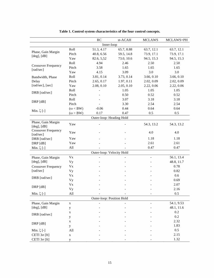
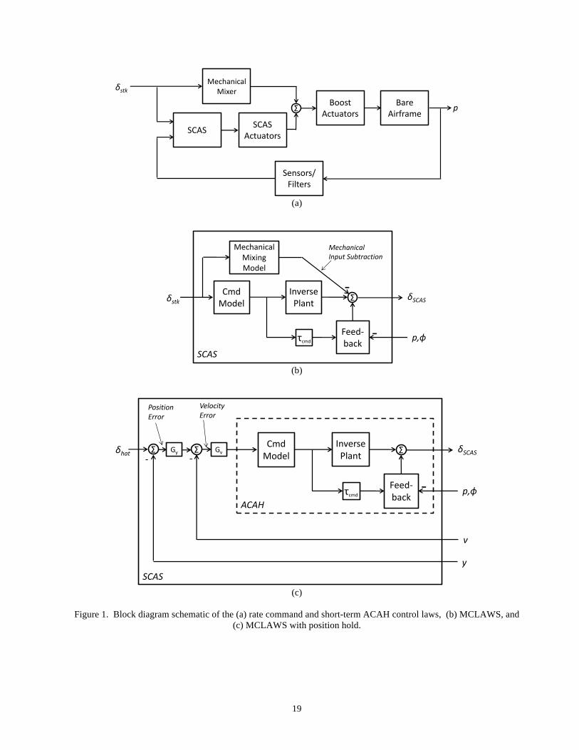
Description of Simulation Experiment Aircraft Model and Flight Control Systems The experiment was conducted using the OH-58D aircraft that has a maximum gross weight of about 5,500 lbs. and includes a three-axis (pitch, roll, and yaw) partial authority (±10%) Stability Control Augmentation System (SCAS). The state-space flight dynamics models of the aircraft were extracted using system identification (Ref. 17) from flight test data. Models, which were identified at hover and 80 knots from previous research (Ref. 12), were ‘stitched’ together along with trim data to develop a continuous dynamics model (Ref. 17) that is valid up to about 100 knots. The Control Equivalent Turbulence Input (CETI) model (Ref. 18) was configured for the OH-58D and incorporated into the analysis model to provide realistic turbulence for the simulation. Four different control system concepts were implemented as part of this experiment, which are described in the following sections. Rate Command (RC) The RC system is the baseline control system of the OH-58D. It provides a rate command response type that includes rate stabilization via an angular rate feedback loop and a control input feed-forward loop for control augmentation. As described in Ref. 12, these control laws were hand-tuned in flight, and are not optimized to meet the handling qualities requirements as are the other three control system concepts. However, this RC control system is representative of the OH-58D as well as many of the helicopters that are used for civil EMS type missions today, and so it was picked for this study. Figure 1a shows a block diagram schematic of the RC control system. Pilot stick inputs are fed into both a mechanical mixer and the SCAS. The SCAS outputs drive the limited-authority SCAS actuators, which are summed with the mixed pilot stick commands, and used to drive the boost actuators. Finally, the rates from the bare-airframe are fed back to the SCAS. Table 1 shows the control system characteristics of the rate command system. The rate command control system exhibits Level 2 performance for closed-loop damping and pitch axis phase margin. Short-term Attitude Command/Attitude Hold (st-ACAH) The st-ACAH control system was developed and test flown in 2011 as a possible upgrade to the OH-58D SCAS (Ref. 12). This system uses the same hardware as the rate command system shown in Figure 1a, however lagged-rate gains, equivalent to washed-out attitude
feedback, are used to achieve a st-ACAH response type in pitch and roll. The st-ACAH concept could be implemented for any aircraft with an existing rate-response type SCAS using the same control hardware architecture, reducing the cost of any potential upgrades. The st-ACAH response type is provided in hover up to 40 knots, and is blended to RC from 40 to 60 knots with RC beyond 60 knots. The control system characteristics are provided in Table 1, which shows that this concept meets ADS-33 Level 1 requirements with improved damping over the rate command system. As presented in Ref. 12, the st-ACAH control system rendered Level 1 handling qualities ratings in a GVE. However, the lack of a long-term attitude hold capability, RCDH and RCHH resulted in Level 2 (HQR 4) handling qualities in the DVE. Modernized Control Laws (MCLAWS) The MCLAWS system was developed to expand on the st-ACAH work that was done. The design objectives were to build on the good short-term response characteristics of the st-ACAH control laws, but extend the attitude hold capabilities to steady-state using a direct attitude measurement that is available on most modern helicopters. Originally developed for the AH-64 Apache (Ref. 19), MCLAWS achieves an ACAH response type in pitch and roll using existing partial-authority SCAS actuators with special attention paid to minimizing the saturation of the SCAS servos. Figure 1b shows a block diagram schematic of MCLAWS, which replaces the simple SCAS block in Figure 1a. MCLAWS subtracts out the mechanical stick to actuator path, and replaces it with an explicit model following control system, which consists of an attitude response command model, an inverse plant, and a feedback loop. These control laws were adapted and optimized using CONDUIT® (Ref. 20) for the OH-58D for this experiment to ensure that within the SCAS authority, the aircraft response will track the command model. In the yaw axis, MCLAWS includes a Rate Command/Direction Hold (RCDH) mode, which captures and maintains a heading once the pilot releases the pedals. As with the st-ACAH control systems, MCLAWS are blended to rate command from 40 to 60 knots. It should be noted that a sensor package providing attitude measurements would need to be added to the aircraft to achieve an MCLAWS control system. Table 1 shows the control system characteristics of the MCLAWS design. The command models in the MCLAWS design were tuned to achieve the same Level 1 piloted bandwidths as the st-ACAH design, as seen in the table. The feedback gains were optimized to give the same crossover frequencies and disturbance rejection bandwidths as the st-ACAH design, while achieving better closed-loop damping.
6
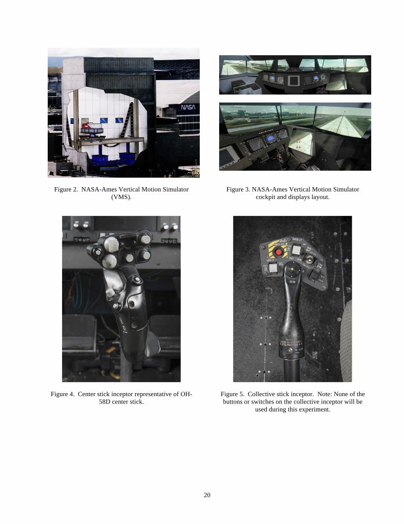
MCLAWS plus Position Hold (MCLAWS+PH) A position hold functionality was added to MCLAWS that engages when the center stick is in detent and the speed is below 5 knots. Below 5 knots, a deceleration to hover is initiated with position hold engaging when the ground speed is below 0.5 knots. The system allows the pilot to ‘adjust’ the hover position with a ‘hat’ switch on the cyclic control inceptor. No altitude hold mode was implemented in the MCLAWS+PH control system. Figure 1c shows the block diagram schematic for the velocity and position outer-loops wrapped around the ACAH inner-loop. Since these loops are only active with the stick in the detent position, subtracting out the direct stick to actuator path using the mechanical mixing model is not needed. Table 1 shows the control system characteristics of the MCLAWS+PH design. The inner-loop is identical to the MCLAWS design, as seen in the table. Also shown are the additional velocity and position hold loop characteristics. These loops were optimized in CONDUIT® using a nested optimization approach as presented in Ref 21. Table 1 shows that the stability margins are disturbance rejection bandwidths for the outer velocity and position loops all meet the Level 1 requirements. The table also shows the 3σ variations in the position of the helicopter during simulated moderate turbulence. These values are within the ±3 ft requirements of the ADS-33 Hover MTE. Facility The experiment was conducted in the Vertical Motion Simulator at NASA-Ames Research Center, described in Ref. 22 (Figure 2). The Transport Cab (T-Cab) was used. This cab provides the pilot with 205-degree field of view, as well as a chin window, as shown in Figure 3. The simulation facility provides six-degree-of-freedom motion with 60-feet of vertical and 80-feet of lateral travel, which is a unique facility for rotorcraft handling qualities work. Helicopter center stick, collective stick and pedal pilot control inceptors were selected to closely match those of the OH-58D and were installed for the right cockpit seat, the evaluation pilot position. The center stick used for this experiment is shown in Figure 4 and is a cyclic inceptor from a Seahawk, which was judged by a current OH-58 pilot to be the closest available cyclic inceptor to the OH-58D inceptor. The Trim Release button is in the center of the upper panel of the cyclic stick, and the position hold ‘coolie hat’ switch is to the left of the Trim Release button. The Trim Release button removes and re-centers the stick forces when it is pressed in any of the flight control modes. The collective stick used in this experiment is shown in Figure 5. This is representative of
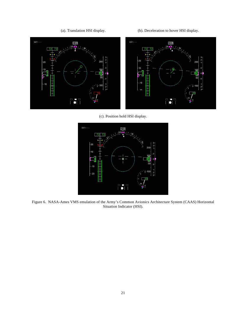
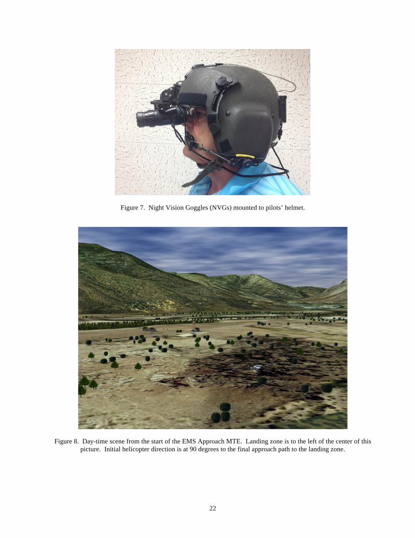
a UH-60 collective stick and was deemed to be sufficient for this particular simulation experiment. Note that none of the button or switches on the collective inceptor were used during this experiment. The primary flight display and the horizontal situation (hover) display, similar to the Army’s Common Avionics Architecture System (CAAS) displays, were provided on the instrument panel. The Horizontal Situation Indicator (HSI) display provides the pilot with some cueing information regarding the current mode when the MCLAWS+PH flight control mode is engaged. Figure 6(a) shows the display in a transition mode with the stick out of detent, or with the speed above 5 knots. Below 5 knots and with the stick in detent, a deceleration to hover is initiated, indicated in Figure 6(b) with a green dot inside the green acceleration circle near the center of the HSI display. When the speed drops below 0.5 knots, position hold is engaged, indicated in Figure 6(c) where the green circle is filled grey. The pilot can ‘adjust’ the hover position with the ‘coolie hat’ switch on the cyclic control inceptor. A single “click” of the ‘coolie hat’ is 1-foot translation, while holding the deflection of the ‘coolie hat’ is a translational rate of 4 ft/sec. Carefully tailored visual scenes of the ADS-33 and EMS type evaluation tasks were developed with attention to task cueing and visual textures in both GVE and DVE conditions. For this experiment, DVE was simulated primarily with the pilots wearing Night-Vision Goggles (NVGs) in a simulated night scene, but also with an unaided night scene. Figure 7 shows a photo of the NVGs mounted to the pilots’ helmet. The goggles used were ITT Exelis Aviator’s Night Vision Imaging System (ANVIS) AN/AVS-6 goggles. Evaluation Tasks and Procedures The test maneuvers flown as part of this experiment included Mission Task Elements (MTEs) from ADS-33 for the scout/attack class rotorcraft, including: Hover, Pirouette, Sidestep, and Acceleration/Deceleration maneuvers. These maneuvers were flown in accordance with the procedures and performance targets outlined in ADS-33 (Ref. 3), with the exception of the Sidestep MTE. For this experiment, the Sidestep MTE was performed using a translation to the right only rather than the right then left translation described in ADS-33. The reason for this change is that the VMS visual system does not provide enough visual cueing out the left side window to enable the aggressive lateral bank and motion to the left. A civilian EMS type mission/task of landing at a remote, minimally prepared site in the presence of obstacles (EMS Approach MTE) was developed and also used in this experiment. The EMS task had the pilot start at 65-knots
7
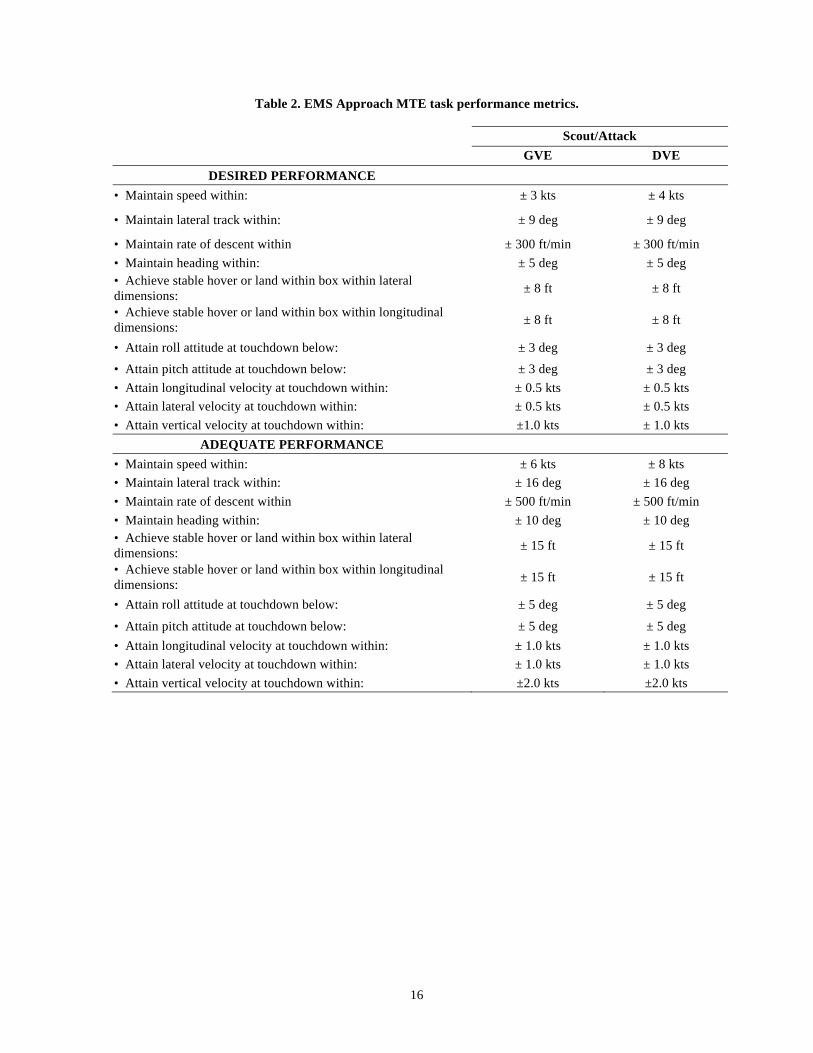
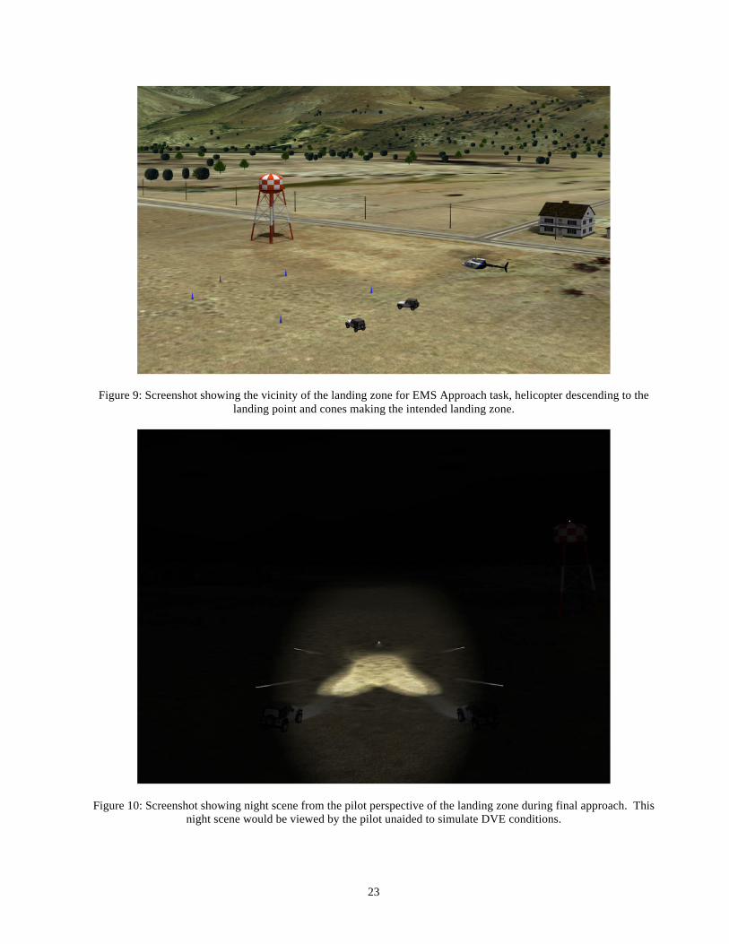
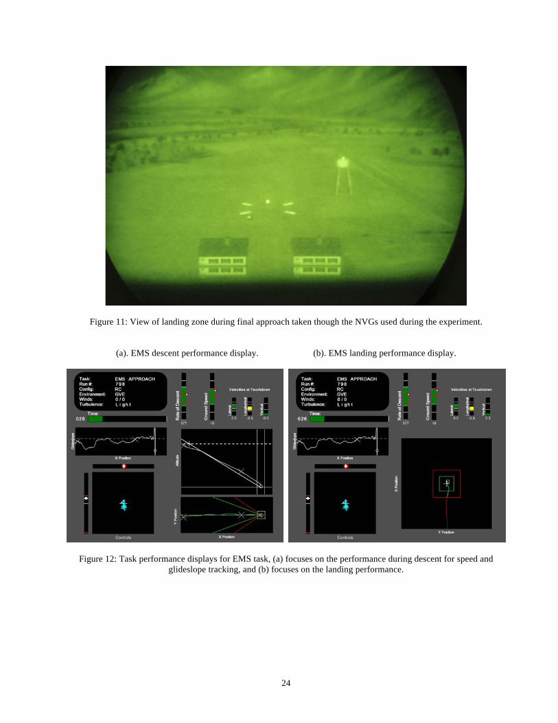
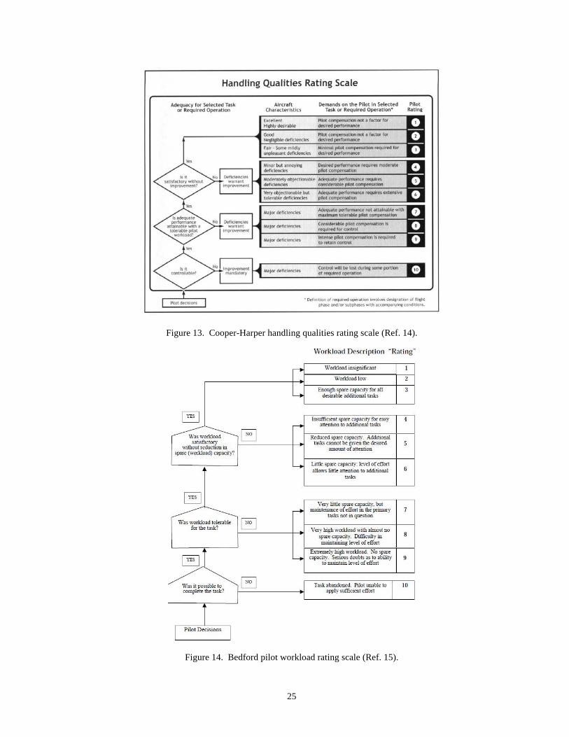
level flight at 250-feet AGL on a heading 90-degrees from the final approach path to the landing zone. Figure 8 shows a picture of the general EMS Approach MTE with the landing zone just to the left of the middle of the picture, centered among the simulated buildings and water tower. The pilot would then make a 90-degree right descending, decelerating turn to an altitude of 200 feet and a speed of 15 knots to prepare to begin the descent. The descent starts when the aircraft was positioned along a nominal 12-degree glideslope to landing in the center of a defined landing zone. The pilot was required to maintain a ground speed of 15 knots during the descent, which translates into about 325 ft/min of descent rate. Figure 9 shows a screenshot from the simulation with the aircraft in the vicinity of the landing zone. The landing zone is marked with cones spaced in a 100x100-foot box, with the desired landing point in the middle of the landing zone. Figure 10 shows an unaided night scene from the pilot perspective of the landing zone during final approach. This night scene would be viewed by the pilot through NVGs and unaided to simulate DVE conditions. For the night scene, the cones marking the extent of the landing zone are replaced by simulated flashlights positioned on the ground pointing towards the center of the landing zone. The headlights of two vehicles are used to also cross illuminate the center of the landing zone, and an ownship mounted spotlight also helps to illuminate the landing zone. Figure 11 shows a view of the landing zone through the NVGs. The NVG scene eliminates the vehicle headlights and the ownship spotlight. The pilot terminated the approach in a hover for 5 seconds over the center of the landing zone before descending to a landing. During the approach and descent, the pilots ‘call out’ when they have acquired the glideslope and are descending towards the landing zone, and a second call when they are initiating the deceleration to the hover position. Table 2 contains the performance standards for the EMS Approach MTE. It should be noted that the performance standards listed in Table 2 are considered to be notional at this stage since this is a proposed new MTE and precise and meaningful performance standards are yet to be established. The performance standards were chosen based on pilot feedback and were aimed at achieving a balance between providing a realistic operational flying task and making the task repeatable across pilots. Figure 12 shows an example of the test engineer displays used to monitor pilot performance metrics for the task, based on the ability of the pilot to maintain speed and glideslope, and their ability to land in the center of the landing zone with minimal ground speed. Following each run, feedback was provided to the pilot on their ability to maintain speed though the approach and landing, their
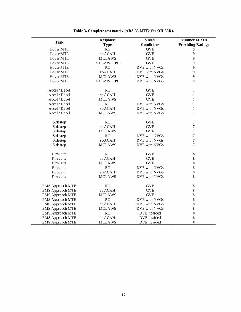
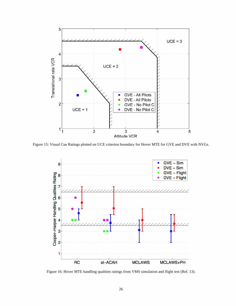
ability to track the desired glideslope, and their landing performance in-terms of distance to the center of the landing zone and their ground speed and attitudes at landing. Pilots were required to complete initial training sessions to familiarize themselves with the OH-58D flight dynamics and the control systems evaluated during this experiment, the ADS-33 MTEs and the EMS Approach MTE, the particulars of the motion and visual cueing provided in the VMS in both GVE and DVE, and operation of the NVGs in DVE. Prior to evaluation runs, the pilots flew each configuration for practice purposes as many times as required until the pilots felt consistent performance could be achieved. The task displays were available for the pilot to look at in the cab following each practice run so that they could see their performance for that particular run. For the formal evaluation runs, pilots were required to perform a minimum of three runs prior to the collection of pilot comments and ratings. If pilots felt that a run was anomalous, or they felt that they needed additional runs to fully evaluate the configuration, they were free to execute additional runs as desired. For the evaluation runs, the information on the task performance displays was read back to the pilot as to their performance in terms of desired and adequate standards for each MTE. The data recorded during the experiment included the pilot control inputs, aircraft state data and the task performance for each of the MTEs evaluated, as well as pilot comments and ratings. The pilot would first run through a questionnaire specifically tailored for this experiment, shown in Appendix A, providing their comments and impressions for each of the questions listed. This questionnaire includes the pilot providing Cooper-Harper Handling Qualities ratings in accordance with Figure 13 (Ref. 14), and an estimate of their spare workload capacity on the Bedford Workload scale shown in Figure 14 (Ref. 15). Pilots were also asked to assign numerical scores from one to nine rating the level of precision obtainable, their ability to be aggressive, the ride quality during the maneuver, and the predictability of the aircraft response to pilot inputs. These questions were developed by Lusardi, et al in Ref. 23, and the application of a numerical rating scale allowed for quantitative analysis of the otherwise qualitative comments. Test Matrix The full matrix of configurations evaluated during this experiment is shown in Table 3. The goal was to have each of the nine experimental test pilots run through this entire test matrix, however this was not possible for all of the pilots. Table 3 also lists the number of test pilots who provided evaluations for each of the configurations. A couple of notes for this test matrix are:
8
- One level of turbulence was used throughout the entire simulation experiment. This turbulence level was set as a trade-off to provide adequate disturbances to increase pilot workload for task performed in GVE, while not providing unnecessarily high workload in more difficult tasks, such as the Hover MTE in DVE with the Rate Command control system.
- All of the maneuvers were flown with no steady winds. Various wind speeds and directions were examined for the Pirouette and EMS Approach tasks, but it was felt that the inclusion of turbulence, particularly in DVE, was sufficient to provide a representative level of pilot workload.
- The MCLAWS+PH control system was evaluated only with the Hover MTE. In initial testing, the Hover MTE proved to be the best MTE at differentiating between the MCLAWS configurations with and without Position Hold activated. The addition of Position Hold for the other ADS-33 MTEs and the EMS Approach MTE did not provide any additional information beyond the MCLAWS control systems.
- The EMS Approach task was set-up in the simulation to be flown from any direction to the landing zone, where the fixed locations of the buildings and terrain would provide different visual cues to the pilots during their descent and landing. Initially it was proposed to have the pilots fly familiarization or practice runs at a particular approach angle, and then use different approach angles for the evaluation runs. However, in order to be consistent, it was decided that all of the familiarization and evaluation runs be flown at the same approach angle to the landing zone for all of the pilots.
- The EMS Approach MTE was flown in DVE unaided as well as DVE with NVGs since the illuminated landing zone provided sufficient cueing for the approach and landing to be flown in DVE unaided. The ADS-33 MTEs that included simulated hover and cueing boards, and lines and cones on the ground, did not provide enough cueing to the pilot when flown in DVE unaided; therefore, they were in DVE with NVGs only.
Results
Over 1400 data runs were performed as part of this experiment with 12 different evaluation pilots, including nine experimental test pilots (XPs) from NASA, U.S. Army, U.S. Navy and FAA, and 3 non-XPs that had extensive OH-58, DVE and/or EMS operational experience.
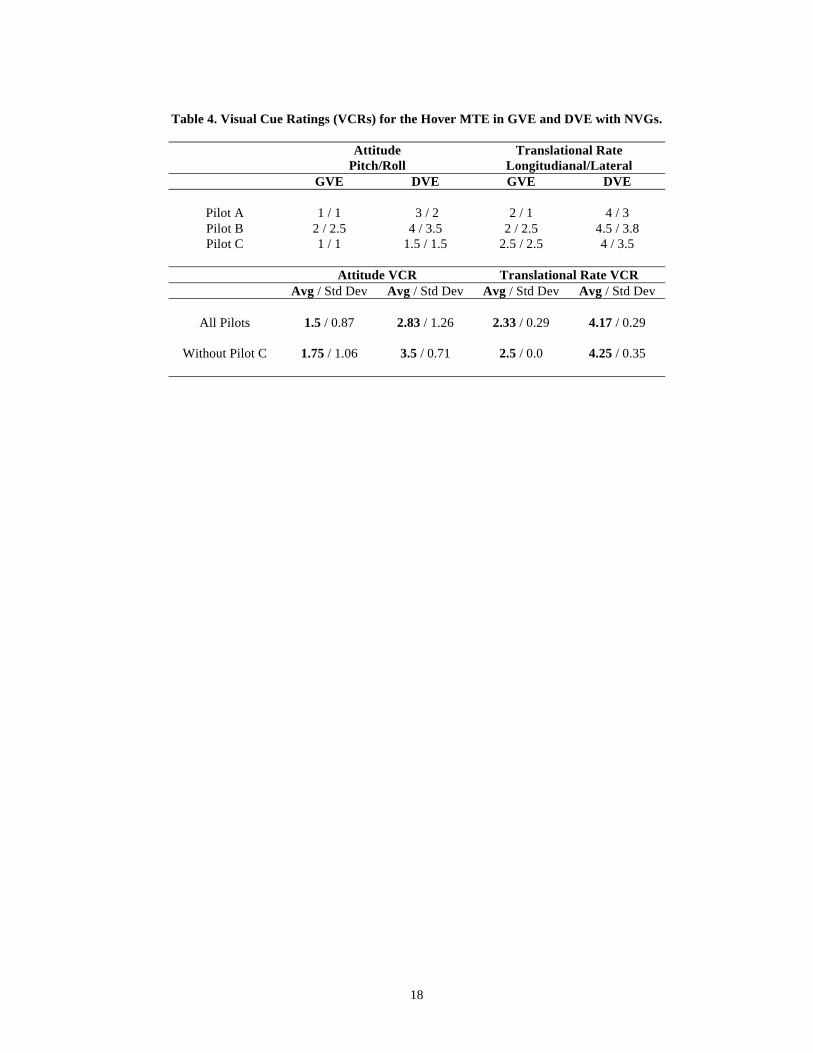
UCE Evaluations: The UCE was evaluated as part of this experiment in both GVE and DVE with NVGs using the procedures outlined in ADS-33 test guide (Ref. 16). As required in ADS-33, the evaluation was conducted using the RC control system for the Hover MTE using the DVE performance standards. The UCE for DVE with an unaided night scene was not evaluated since the simulated ADS-33 Hover MTE course could not be used in DVE unaided conditions. A total of three pilots provided Visual Cue Ratings (VCRs) with the ratings summarized in Table 4. Figure 15 shows average attitude and translational rate VCRs plotted on the UCE Criterion Boundary (Ref. 3). Two sets of VCRs for GVE and DVE are plotted on Figure 15, one (labeled as ‘All Pilots’) with the average VCRs for all of the pilots, and the other (labeled as ‘No Pilot C’) is the average VCRs from the pilots who provided the worst VCR ratings. The VCR results shown in Figure 15 indicate that GVE provides UCE=1 and DVE with NVGs provides UCE=2. These UCE ratings for GVE and DVE with NVGs are consistent with the OH-58D flight test results (Ref. 12), which also had UCE=1 in GVE and UCE=2 in DVE with NVGs. The translational rate VCR ratings shown in Table 4 show that there is no significant different in GVE longitudinal and lateral cueing. However the ratings in DVE are higher for longitudinal translation than lateral, indicating that longitudinal translational rate cueing is poorer than lateral in DVE with NVGs. Hover MTE Results: The effect of control augmentation on Cooper-Harper handling qualities ratings for the ADS-33 Hover MTE in GVE and DVE with NVGs is shown in Figure 16. This figure also shows the flight test data for the OH-58D for GVE and DVE flight with the legacy or baseline rate response control system (for simplicity, this is referred to as the RC control system flight test data in this paper) and st-ACAH control system as presented in Ref. 12. In GVE, all of the pilots provided handling qualities ratings of 4-5 for the RC control system, indicating that this is a solidly Level 2 aircraft for this task in GVE. This is comparable with the OH-58D flight test results with the same RC control architecture, where the two pilots both provided handling qualities ratings of 4. ADS-33 indicates that a RC system is the minimum response type required for Level 1 Handling Qualities in GVE (UCE=1), however for this particular aircraft in the Hover MTE, the RC system produced Level 2 handling qualities. For the st-ACAH control system the average handling qualities rating is 3.5, which is borderline Level 1, and is an improvement of about 1.0 HQR when compared with
9
the RC control system. This indicates that with a moderate augmentation to the RC control system, Level 1 handling qualities can be achieved in GVE for the Hover MTE. These results are comparable with the flight test results for the OH-58, where both flight test pilots gave a HQR 3 for the st-ACAH in GVE. Further augmentation with the MCLAWS and MCLAWS+PH response types produces a Level 1 aircraft with average HQR ratings of about 3.0 for both ACAH control systems, with 5 out of 9 pilots providing ratings of 3 or better for MCLAWS, and 8 out of 9 pilots providing ratings of 3 or better for MCLAWS+PH. These results also show that the addition of Position Hold does not significantly improve the handling qualities ratings for this particular task in GVE. There are no flight test results for comparison for the MCLAWS and MCLAWS+PH response types since the OH-58D is currently not equipped to fly with an ACAH response type, even though the 10% authority SCAS actuators simulated in this experiment show that the current OH-58D SCAS hardware would be sufficient to provide ACAH with MCLAWS in the hover and low speed flight regime. For DVE, an average handling qualities rating of 5.5 was obtained with the RC control system, which is again comparable with the flight test data where the two pilots provided ratings of 5 and 6. For st-ACAH, the improvement is only about 0.5 HQR with the best pilot rating being a 4.5. This is slightly degraded from the flight test results where both pilots provided a HQR of 4 for the Hover MTE in DVE. In comparing all of the Hover MTE simulation results with the flight test data, it is seen that the flight test handling qualities ratings are consistently at the better HQR range obtained from the simulation experiment. A more substantial improvement in handling qualities ratings in DVE is seen with the MCLAWS response type where the improvement is more than 1 rating point as compared with st-ACAH to an average HQR better than 4, and that 3 out of 9 pilots rated this control configuration Level 1 with HQR=3. The addition of Position Hold in DVE improves the ratings by an average of 0.5 to be borderline Level 1, and with 4 out of 9 pilots rating this a Level 1 aircraft with a handling qualities rating of 3. These simulation results are not directly comparable to the ADS-33 requirements for Level 1 handling qualities in DVE (UCE=2) since the MCLAWS control system down not include RCHH. However it is expected that the addition of RCHH to MCLAWS would reduce the workload in the vertical axis and confer Level 1 handling qualities. The pilot longitudinal and lateral stick cut-off frequencies
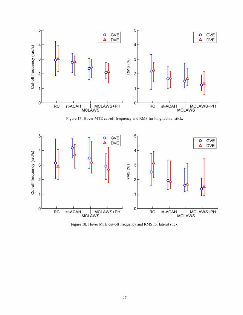
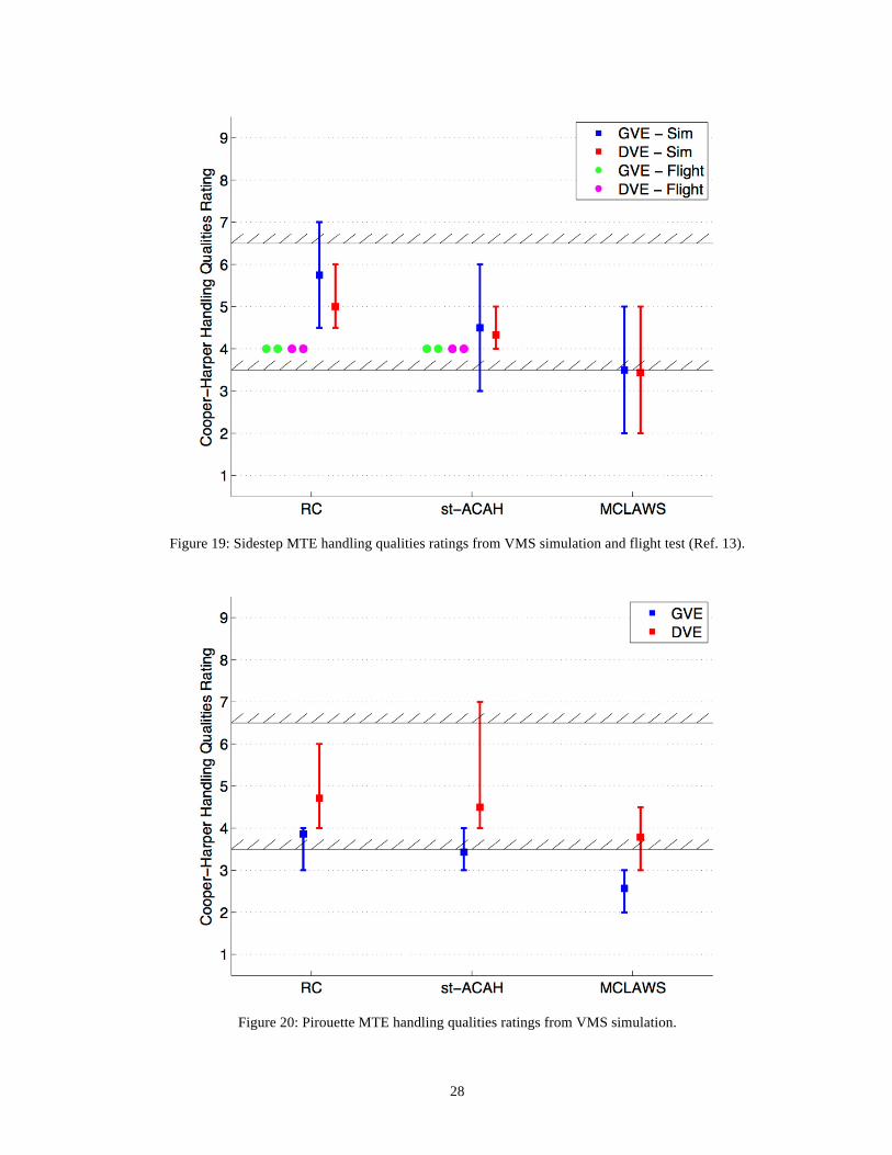
and stick motion Root Mean Squared (RMS) for the Hover MTE are shown in Figures 17 and 18. The cut-off frequency is defined by Tischler and Remple (Ref. 17) and is a good measure of the piloted operating frequency and crossover frequency. For longitudinal stick cutoff frequency and RMS shown in Figure 17, there is no substantial difference between the results from the GVE and DVE cases for any of the control systems examined. The longitudinal stick data also shows that both the cut-off frequency and RMS decrease with additional control augmentation, which indicates a reduction in pilot workload to obtain the improved handling qualities shown in Figure 16. For lateral stick (Figure 18), the cut-off frequency is slightly higher for each control system in GVE as compared with DVE. This is possibly due to the increased precision required in the vertical axis (that may influence the other axes) for the Hover MTE in GVE that increases the pilot workload to maintain the desired task performance. An interesting result in Figure 18 is that the cut-off frequency increases significantly from RC to st-ACAH for both the GVE and DVE cases. This is likely due to the additional lateral axis bandwidth available with the st-ACAH control system that the pilot is using to improve the task performance and handling qualities rating with the st-ACAH control system, as shown in Figure 16. The same is not true for the longitudinal stick (Figure 17), where the cut-off frequency consistently decreases with additional augmentation. Sidestep MTE Results: Figure 19 shows the handling qualities ratings for the ADS-33 Sidestep MTE in GVE and DVE for the RC, st-ACAH and MCLAWS control systems. It should be noted that Sidestep MTE performed in this simulation experiment differed from the Sidestep MTE described in ADS-33 in that the translation was performed only to the right whereas ADS-33 requires a right then left translation. The handling qualities data shown in Figure 19 show a lot of variation in the individual ratings as indicated by the size of the error bars for the different control systems and visual conditions. This wide range in pilot ratings is due to the lack of visual cueing provided in the VMS for this particular MTE. With this in mind, the results shown in Figure 19 indicate a progression of improved handling qualities from the RC control system to the st-ACAH and MCLAWS control systems, with the average handling qualities rating being borderline Level 1 with the MCLAWS control system. Another interesting trend to note from Figure 19 is that the Sidestep MTE performed in DVE has better or equal
10
average HQRs as when performed in GVE. This is because the DVE standards for this MTE are significantly less aggressive. Performing this task to GVE standards, especially with the least amount of augmentation (RC) was very difficult in the aircraft, and the task performance standards dominate over the available cues. Acceleration / Deceleration MTE Results: The limitations of the visual cueing in the VMS were even more apparent for the Acceleration/Deceleration MTE than they were for the Sidestep MTE. The main issues with the Acceleration/Deceleration MTE is the forward out-of-the-window visuals in the nose-down acceleration portion and nose-up deceleration portions of the MTE were not sufficient to provide the pilot with adequate ground references during these key portions of the MTE. Due to the extreme pitch attitudes and lack of cues in the simulation, the Acceleration/Deceleration MTE was evaluated by only 2 pilots during the experiment, and the results are not being reported in this paper. Pirouette Results: Figure 20 shows the handling qualities ratings for the Pirouette MTE in GVE and DVE for the RC, st-ACAH and MCLAWS control systems. For GVE, the RC control system produces a Level 2 response with an average handling qualities rating of about 4, which is consistent with the average handling qualities rating of 4.5 achieved for the Hover MTE (Figure 16). The handling qualities rating improves to borderline Level 1 with an average rating of 3.5 with the st-ACAH control system, and solidly Level 1 with an average rating of 2.5 for the MCLAWS control system; all pilots rated MCLAWS as Level 1 for the Pirouette MTE. The DVE results in Figure 20 shows that the handling qualities ratings degrade by between 1 and 1.5 HQR when compared to the individual GVE results with the same control system response types. The average rating with the MCLAWS control system in DVE is less than 4, and 3 out of 8 pilots rated this as Level 1. It is expected that the addition of RCHH for the Pirouette MTE would further reduce the workload in the vertical axis and confer Level 1 handling qualities, and is consistent with the ADS-33 requirements for Level 1 in DVE. It is worth noting that the improvement in handling qualities rating from RC to st-ACAH control systems for the Pirouette MTE is about 0.5 whereas the improvement is about 1.0 for the Hover MTE (Figure 16). This is primarily due to the st-ACAH improving the short-term response characteristics, which is less important for the Pirouette MTE than the Hover MTE due to the lower task
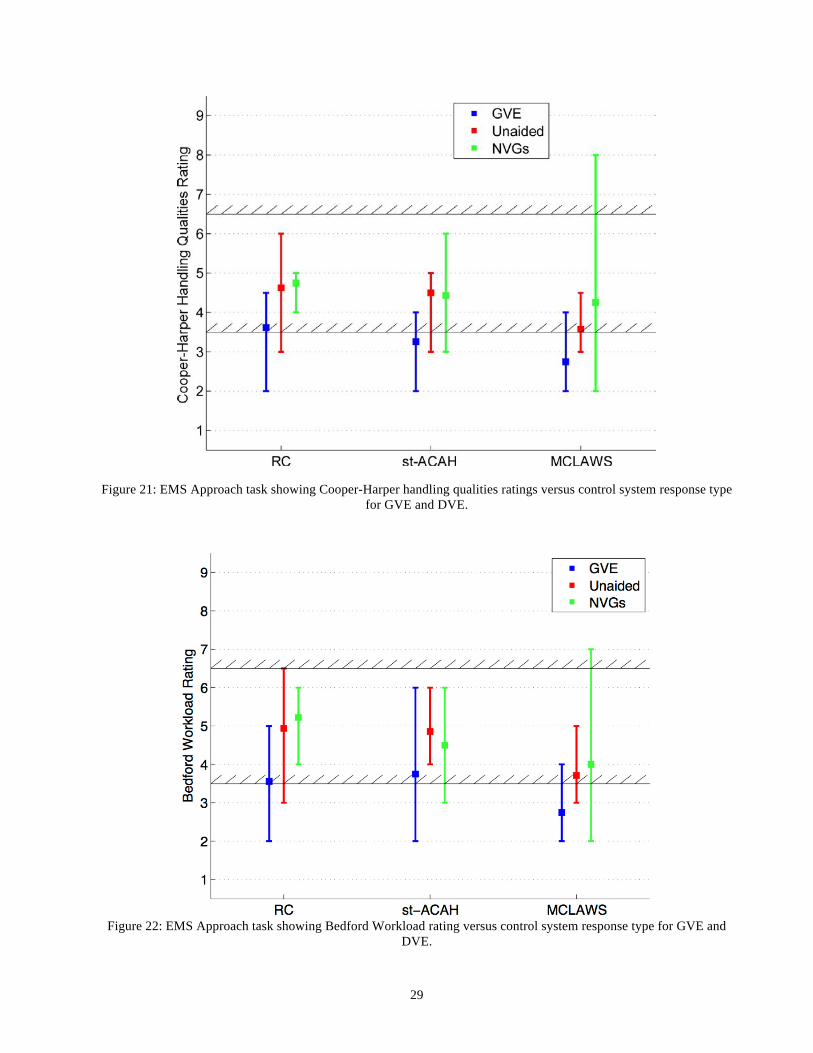
bandwidth of the Pirouette MTE compared with the Hover MTE, and results in a lower improvement in handling qualities ratings when compared with the Hover MTE. It is also worth noting that one pilot provided a HQR of 7 for st-ACAH in DVE, and that this pilot had only limited experience in flying with NVGs. This particular result shows the effect of a “low-time” pilot and supports the assertion of Ref. 8 that lack of flight time and proficiency (in this case with NVGs) can significantly increase workload and degrade handing qualities ratings. EMS Approach MTE Results: Figure 21 shows handling qualities ratings for the EMS Approach MTE developed for this experiment and described earlier in this paper. This figure shows results for GVE and DVE with the RC, st-ACAH and MCLAWS control systems. For GVE, the aircraft is borderline Level 1 with an average handling qualities rating of about 3.5 for the RC control system and improves to Level 1 with the st-ACAH and MCLAWS control systems. A similar trend or improvement is obtained with DVE unaided and DVE with NVGs for all of the control systems shown. The handling qualities ratings are Level 2 with an average rating of 4.5 for the RC and st-ACAH control system, and improving to borderline Level 1 with MCLAWS with an average rating of 3.5. With the descending-approach in this MTE, the potential benefits of adding altitude hold (RCHH) to the MCLAWS control system maybe less for the EMS Approach MTE than for the Hover and Pirouette MTEs. Pilots commented that in DVE they could not pick up speed and vertical velocity changes as quickly or as accurately as in GVE, particularly during the initiation and tracking of the glideslope, which was a key factor in the degraded handling qualities ratings in DVE. It is worth noting that saturation of the actuators of the 10% authority SCAS was not a factor in the handling qualities shown in Figure 18 for the EMS Approach MTE. This indicates that a 10% authority SCAS would generally be sufficient to provide good handling qualities from st-ACAH response type with software upgrades, or an ACAH response type with attitude feedback for this particular MTE. In comparing the st-ACAH and RC control systems, pilots commented that the helicopter response was “smoother” with st-ACAH, particularly during the 90-degree turn, and was “more controllable” during the deceleration and landing phase of the task. The improvement in HQRs from RC to st-ACAH for the EMS Approach MTE (Figure 21) is smaller than the improvement seen for the Hover MTE (Figure 16). This is consistent with the comparison between the Hover and Pirouette MTEs, where a smaller HQR improvement is
11
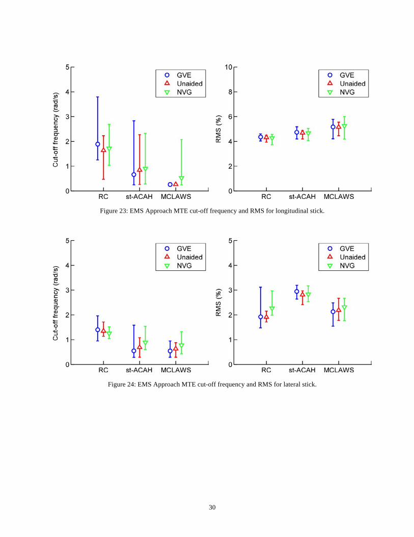
seen with the Pirouette MTE (Figure 20) than with the Hover MTE. This is due to the fact that the st-ACAH control system primarily improving the short-term response characteristics, which are less important for the EMS Approach MTE and the Pirouette MTE than for the Hover MTE. The Hover MTE also requires the pilot to be more aggressive to attain the level of precision required by the task, and is a higher bandwidth task than the Pirouette and EMS Approach MTEs. Figure 22 shows the Bedford Workload rating versus control system response type for the same cases shown in Figure 21. The Bedford Workload ratings scale requires the pilot to rate the level of workload associated with a task, based on the amount of spare capacity they feel they have to perform additional tasks, with lower ratings indicating lower workload and higher spare capacity. For the current experiment, pilots are required to maintain situational awareness in order to fly the EMS Approach MTE in accordance with the requirements listed in Table 2. The results shown in Figure 22 indicate that the pilots’ workload is significantly increased when performing the task in DVE compared with GVE since flying the task in DVE requires addition pilot workload to maintain situational awareness in order to achieve required mission performance. Figure 22 also shows that there is little difference in workload in DVE unaided versus DVE with NVGs. The trends in workload shown in Figure 22 are consistent with the handling qualities ratings shown in Figure 21 in that increased levels of control system augmentation improve the handling qualities ratings while at the same time reduce the pilot workload required. It is worth noting that one pilot provided a HQR of 6 for st-ACAH and a HQR of 8 in DVE with NVGs. This pilot had limited experience with NVGs and these results highlight that using NVGs without sufficient flight time and proficiency can significantly degrade handing qualities. The pilot longitudinal and lateral stick cut-off frequencies and stick RMS for the EMS Approach MTE are shown in Figures 23 and 24. The pilot cutoff frequencies decrease with additional control augmentation, which is seen for both the longitudinal and lateral stick inputs, and is consistent with the improvement in handling qualities ratings with control augmentation shown in Figure 21. Comparing the cut-off frequencies for the EMS Approach MTE (Figures 23 and 24) with the cutoff frequencies for the Hover MTE (Figures 17 and 18), shows that the frequencies for the EMS Approach MTE are significantly less than those for the Hover MTE. The reason for this is that the Hover MTE has a significantly higher task bandwidth than the EMS Approach MTE requiring a higher pilot workload to obtain the required task performance.
Summary and Conclusions A piloted simulation experiment was in the NASA-Ames Vertical Motion Simulator that examined and quantified the effects of limited authority control system augmentation on handling qualities and task performance in both good and degraded visual environments. The vehicle model used for the experiment was the OH-58D with similar size, weight and performance, and the same 4-bladed rotor system as the Bell 407 civilian helicopter that is commonly used for medical evacuation and emergency medical services. The control systems investigated as part of this study include the baseline aircraft Rate Command system, a short-term Attitude Command/Attitude Hold system that uses lagged-rate feedback rather than attitude feedback to provide a short-term attitude response, Modernized Control Laws that provide an Attitude Command/Attitude Hold control response type, and Modernized Control Laws with an additional Position Hold function. Evaluation tasks included the ADS-33 Hover, Sidestep, Acceleration/Deceleration, and Pirouette Mission Task Elements, as well as a new proposed EMS task that includes a remote landing at a minimally prepared landing site. DVE was simulated with NVGs and a night scene unaided. A total of nine experimental test pilots participated in the four-week simulation experiment. Data recorded included handling qualities ratings, workload using the Bedford Workload scale, and task performance. The Usable Cue Environment for this experiment in the VMS was found to be UCE=1 in GVE and UCE=2 in DVE with NVGs. This is consistent with the flight tests on the OH-58D and allows for a direct comparison between the current simulation results and flight test data. The following conclusions can be drawn from this experiment:
- The handling qualities ratings for the Hover MTE in this simulation experiment are consistent with those from the OH-58D flight test for the RC and st-ACAH control systems, providing important anchor points for the results of the simulation experiment.
- The st-ACAH control system, that can be
achieved with software upgrades only on the OH-58D and other helicopters that have rate stabilization, improves the handling qualities for all of the MTEs examined in this experiment, particularly those that have a high task bandwidth, such as the ADS-33 Hover MTE.
- The MCLAWS control system that provides an
ACAH response type produces Level 1 handling
12
qualities for all of the MTEs examined in this experiment in GVE, and borderline Level 1 handling qualities for the MTEs in DVE. The addition of Position Hold improves the average HQR only by about 0.5 for the Hover MTE. It is likely that the addition of altitude hold with RCHH (as required by ADS-33 for some MTEs) would result in Level 1 handling qualities in DVE.
- The 10% authority stability augmentation system
was sufficient to achieve an ACAH response type with the MCLAWS control system up to the transition speed of 40 knots, and actuator saturation was not a factor in the handling qualities ratings for any of the MTEs examined during this simulation experiment.
- The results for the EMS Approach MTE were
consistent with those obtained for the Hover MTE where handling qualities improved with increased augmentation, and borderline Level 1 handing qualities were achieved with MCLAWS in DVE. Pilots commented that the EMS Approach MTE, developed for this experiment, is representative of civilian operations and was a good task to highlight the differences in pilot workload and handling qualities between the different control systems tested.
- The results highlighted the importance of flight
time and proficiency when using NVGs. One pilot, who had limited experience with NVGs, provided significantly degraded handling qualities ratings (Level 3 for some MTEs), which illustrated that NVGs alone are not sufficient to improve handing qualities without adequate training.
References
1. Anon., “Aviation Safety Technologies Report,” Acquisition and Technology Programs Task Force (ATP TF), Department of Defense Aviation Safety Technologies Report, Washington, DC: Defense Safety Oversight Council, Office of the Under Secretary of Defense for Personnel and Readiness, Program Budget Request 10-15, Program Decision Memorandum, April 30, 2009.
2. Anon., US Joint Helicopter Safety Analysis Team: Year 2000 Report to the International Helicopter Safety Team, September 2007.
3. Anon., "Handling Qualities Requirements for Military Rotorcraft", Aeronautical Design Standard-33
(ADS-33E-PRF), US Army Aviation and Missile Command, March 21, 2000.
4. Brown, K., “Surviving DVE: Q&A with Tony Pots,” Rotor & Wing, Vol. 46, No. 9, September 2012, pp. 34-37.
5. Dugan, D., Delamer, K. J., “The implications of Handling Qualities in Civil Helicopter Accidents Involving Hover and Low Speed Flight”, NASA/TM—2005-213473, November, 2005.
6. Harris F. D., Kasper, E. F., Iseler, L. E., ”US Civil Rotorcraft Accidents, 1963 Through 1997”, NASA/TM-2000-209597, USAAMCOM-TR-00-A-006, December 2000.
7. Anon., ”Helicopter Flight in Degraded Visual Conditions”, CAA Paper 2007/03, Safety Regulation Group, CAA, September 2007.
8. Key, D. L., “Analysis of Army Helicopter Pilot Error Mishap Data and the Implications for Handling Qualities”, 25th European Rotorcraft Forum, Rome, Italy, September 14-16th, 1999.
9. Hoh, R. H., Mitchell, D. G., Aponso, B. L., Key, D. L., and Blanken C. L., “Background Information and User’s Guide for Handling Qualities Requirements for Military Rotorcraft,” USAAVSCOM TR 89-A-008, December 1989.
10. Hoh, R. H., “Handling Qualities Criterion for Very Low Visibility Rotorcraft NOE Operations,” Presented at the AGARD Flight Mechanics Panel Meeting, Rotorcraft Design for Operations, Amsterdam, The Netherlands, October 1986.
11. Hoh, R. H., Baillie, S. W., Morgan, J. M., “Flight Investigation of the Tradeoff between Augmentation and Displays for NOE Flight in Low Visibility,” Presented at the Midwest Regional National Specialist’s Meeting on Rotorcraft Flight Controls and Avionics, American Helicopter Society, Cherry Hill, New Jersey, October 13-15, 1987.
12. Berger, T., Tischler, M. B., Blanken, C. B., Fujizawa, B. T., Harding, J. W., Borden, C. C., Cothren, L. E., Wright, J. J., Arterburn, D. R., and Pfrommer, M. R., “Improved Handling Qualities for the OH-58D Kiowa Warrior in the Degraded Visual Environment,” presented at the American Helicopter Society 67th Annual Forum, Virginia Beach, Virginia, May 3-5, 2011.
13. Stephens, Ernie, “Cobham Displays HeliSAS on Bell 407,” Rotor & Wing,
13
http://www.aviationtoday.com/rw/topstories/Cobham-Displays-HeliSAS-on-Bell-407_78885.html, April 1, 2013.
14. Cooper, G. E. and Harper, R. P., “The Use of Pilot Rating in the Evaluation of Aircraft Handling Qualities,” NASA TN D-5153, April 1969.
15. Roscoe, A. H., and Ellis, G. A., “A Subjective Rating Scale for Assessing Pilot Workload in Flight: A Decade of Practical Use,” Royal Aerospace Establishment, Technical Report TR 90019, March 1990.
16. Blanken, C. L., Hoh, R. H., Mitchell, D. G., and Key, D. L., "Test Guide for ADS-33E-PRF", Special Report AMR-AF-08-07, July 2008.
17. Tischler, M. B. and Remple, R. K., Aircraft and Rotorcraft System Identification: Engineering Methods and Flight Test Examples Second Edition, AIAA, 2012.
18. Lusardi, J. A., von Gruenhagen, W., Seher-Weiss, S., "Parametric Turbulence Modeling for Rotorcraft Applications, Approach, Flight Tests and Verification," presented at the Rotorcraft Handling Qualities Conference, University of Liverpool, UK, Nov 2008.
19. Harding, J. W., Moody, S. J., Jeram, G. J., Mansur, M. H., and Tischler, M. B., “Development of Modern Control Laws for the AH-64D in Hover/Low Speed
Flight,” presented at the American Helicopter Society 62nd Annual Forum, Phoenix, AZ, May 2006.
20. Tischler, M. B., Ivler, C. M., Mansur, M. H., Cheung, K. K., Berger, T., and Berrios, M., “Handling-Qualities Optimization and Trade-offs in Rotorcraft Flight Control Design," presented at the Rotorcraft Handling Qualities Conference, University of Liverpool, UK, Novebmer 2008.
21. Mansur, M. H. and Tischler, M. B., “Flight Test Comparison of Alternate Strategies for Multi-Loop Control Law Optimization,” presented at the American Helicopter Society 69th Annual Forum, Phoenix, AZ, May 2013.
22. Aponso, B. L., Tran, D. T., and Schroeder, J. A., “Rotorcraft Research at the NASA Vertical Motion Simulator,” presented at the American Helicopter Society 64th Annual Forum, Montreal, Canada, April 29 - May 1, 2008.
23. Lusardi, J. A., Blanken, C. L., Ott, C. R., Malpica, C. A., and von Grunhagen, W., “In Flight Evaluation of Active Inceptor Force-Feel Characteristics and Handling Qualities,” presented at the American Helicopter Society 68th Annual Forum, Fort Worth, Texas, May 1 – 3, 2012.
14
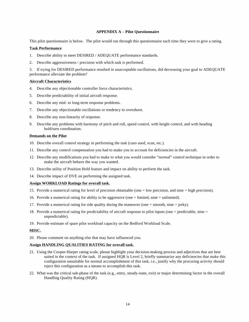
APPENDIX A – Pilot Questionnaire This pilot questionnaire is below. The pilot would run through this questionnaire each time they were to give a rating.
Task Performance
1. Describe ability to meet DESIRED / ADEQUATE performance standards.
2. Describe aggressiveness / precision with which task is performed.
3. If trying for DESIRED performance resulted in unacceptable oscillations, did decreasing your goal to ADEQUATE performance alleviate the problem?
Aircraft Characteristics
4. Describe any objectionable controller force characteristics.
5. Describe predictability of initial aircraft response.
6. Describe any mid- to long-term response problems.
7. Describe any objectionable oscillations or tendency to overshoot.
8. Describe any non-linearity of response.
9. Describe any problems with harmony of pitch and roll, speed control, with height control, and with heading hold/turn coordination.
Demands on the Pilot
10. Describe overall control strategy in performing the task (cues used, scan, etc.).
11. Describe any control compensation you had to make you to account for deficiencies in the aircraft.
12. Describe any modifications you had to make to what you would consider “normal” control technique in order to make the aircraft behave the way you wanted.
13. Describe utility of Position Hold feature and impact on ability to perform the task.
14. Describe impact of DVE on performing the assigned task.
Assign WORKLOAD Ratings for overall task.
15. Provide a numerical rating for level of precision obtainable (one = low precision, and nine = high precision).
16. Provide a numerical rating for ability to be aggressive (one = limited, nine = unlimited).
17. Provide a numerical rating for ride quality during the maneuver (one = smooth, nine = jerky).
18. Provide a numerical rating for predictability of aircraft response to pilot inputs (one = predictable, nine = unpredictable).
19. Provide estimate of spare pilot workload capacity on the Bedford Workload Scale.
MISC.
20. Please comment on anything else that may have influenced you.
Assign HANDLING QUALITIES RATING for overall task.
21. Using the Cooper-Harper rating scale, please highlight your decision-making process and adjectives that are best suited in the context of the task. If assigned HQR is Level 2, briefly summarize any deficiencies that make this configuration unsuitable for normal accomplishment of this task, i.e., justify why the procuring activity should reject this configuration as a means to accomplish this task.
22. What was the critical sub-phase of the task (e.g., entry, steady-state, exit) or major determining factor in the overall Handling Quality Rating (HQR).
15
Table 1. Control system characteristics of the four control concepts.
RC st-ACAH MCLAWS MCLAWS+PH
Inner-loop
Phase, Gain Margin [deg], [dB]
Roll 51.3, 4.17 65.7, 8.88 63.7, 12.1 63.7, 12.1 Pitch 40.8, 6.56 59.5, 14.8 73.9, 17.1 73.9, 17.1 Yaw 82.6, 5,52 73.0, 10.6 94.5, 15.3 94.5, 15.3
Crossover Frequency [rad/sec]
Roll 4.94 2.46 2.50 2.50 Pitch 3.58 1.65 1.65 1.65 Yaw 4.15 3.09 3.0 3.0
Bandwidth, Phase Delay [rad/sec], [sec]
Roll 3.81, 0.14 3.73, 0.14 3.66, 0.10 3.66, 0.10 Pitch 2.65, 0.17 1.97, 0.11 2.02, 0.09 2.02, 0.09 Yaw 2.08, 0.10 2.05, 0.10 2.22, 0.06 2.22, 0.06
DRB [rad/sec] Roll - 1.05 1.05 1.05 Pitch - 0.50 0.52 0.52
DRP [dB] Roll - 3.07 3.18 3.18 Pitch - 3.30 2.54 2.54
Min. ζ [-] (ω < BW) -0.06 0.44 0.64 0.64 (ω > BW) 0.17 0.47 0.5 0.5
Outer-loop: Heading Hold Phase, Gain Margin [deg], [dB]
Yaw - - 54.3, 13.2 54.3, 13.2
Crossover Frequency [rad/sec]
Yaw - - 4.0 4.0
DRB [rad/sec] Yaw - - 1.18 1.18 DRP [dB] Yaw - - 2.61 2.61 Min. ζ [-] All - - 0.47 0.47
Outer-loop: Velocity Hold
Phase, Gain Margin [deg], [dB]
Vx - - - 56.1, 13.4 Vy - - - 48.8, 11.7
Crossover Frequency [rad/sec]
Vx - - - 0.78 Vy - - - 0.82
DRB [rad/sec] Vx - - - 0.6 Vy - - - 0.69
DRP [dB] Vx - - - 2.07 Vy - - - 2.16
Min. ζ [-] All - - - 0.5 Outer-loop: Position Hold
Phase, Gain Margin [deg], [dB]
x - - - 54.1, 9.53 y - - - 48.1, 11.6
DRB [rad/sec] x - - - 0.2 y - - - 0.2
DRP [dB] x - - - 2.32 y - - - 1.83
Min. ζ [-] All - - - 0.5 CETI 3σ [ft] x - - - 2.15 CETI 3σ [ft] y - - - 1.32
16
Table 2. EMS Approach MTE task performance metrics.
Scout/Attack
GVE DVE
DESIRED PERFORMANCE
• Maintain speed within: ± 3 kts ± 4 kts
• Maintain lateral track within: ± 9 deg ± 9 deg
• Maintain rate of descent within ± 300 ft/min ± 300 ft/min
• Maintain heading within: ± 5 deg ± 5 deg
• Achieve stable hover or land within box within lateral dimensions:
± 8 ft ± 8 ft
• Achieve stable hover or land within box within longitudinal dimensions:
± 8 ft ± 8 ft
• Attain roll attitude at touchdown below: ± 3 deg ± 3 deg
• Attain pitch attitude at touchdown below: ± 3 deg ± 3 deg
• Attain longitudinal velocity at touchdown within: ± 0.5 kts ± 0.5 kts
• Attain lateral velocity at touchdown within: ± 0.5 kts ± 0.5 kts
• Attain vertical velocity at touchdown within: ±1.0 kts ± 1.0 kts
ADEQUATE PERFORMANCE
• Maintain speed within: ± 6 kts ± 8 kts
• Maintain lateral track within: ± 16 deg ± 16 deg
• Maintain rate of descent within ± 500 ft/min ± 500 ft/min
• Maintain heading within: ± 10 deg ± 10 deg
• Achieve stable hover or land within box within lateral dimensions:
± 15 ft ± 15 ft
• Achieve stable hover or land within box within longitudinal dimensions:
± 15 ft ± 15 ft
• Attain roll attitude at touchdown below: ± 5 deg ± 5 deg
• Attain pitch attitude at touchdown below: ± 5 deg ± 5 deg
• Attain longitudinal velocity at touchdown within: ± 1.0 kts ± 1.0 kts
• Attain lateral velocity at touchdown within: ± 1.0 kts ± 1.0 kts
• Attain vertical velocity at touchdown within: ±2.0 kts ±2.0 kts
17
Table 3. Complete test matrix (ADS-33 MTEs for OH-58D).
Task Response
Type Visual
Conditions Number of XPs
Providing Ratings Hover MTE RC GVE 9 Hover MTE st-ACAH GVE 9 Hover MTE MCLAWS GVE 9 Hover MTE MCLAWS+PH GVE 9 Hover MTE RC DVE with NVGs 9 Hover MTE st-ACAH DVE with NVGs 9 Hover MTE MCLAWS DVE with NVGs 9 Hover MTE MCLAWS+PH DVE with NVGs 9
Accel / Decel RC GVE 1 Accel / Decel st-ACAH GVE 1 Accel / Decel MCLAWS GVE 1 Accel / Decel RC DVE with NVGs 1 Accel / Decel st-ACAH DVE with NVGs 1 Accel / Decel MCLAWS DVE with NVGs 1
Sidestep RC GVE 7 Sidestep st-ACAH GVE 7 Sidestep MCLAWS GVE 7 Sidestep RC DVE with NVGs 7 Sidestep st-ACAH DVE with NVGs 7 Sidestep MCLAWS DVE with NVGs 7
Pirouette RC GVE 8 Pirouette st-ACAH GVE 8 Pirouette MCLAWS GVE 8 Pirouette RC DVE with NVGs 8 Pirouette st-ACAH DVE with NVGs 8 Pirouette MCLAWS DVE with NVGs 8
EMS Approach MTE RC GVE 8 EMS Approach MTE st-ACAH GVE 8 EMS Approach MTE MCLAWS GVE 8 EMS Approach MTE RC DVE with NVGs 8 EMS Approach MTE st-ACAH DVE with NVGs 8 EMS Approach MTE MCLAWS DVE with NVGs 8 EMS Approach MTE RC DVE unaided 8 EMS Approach MTE st-ACAH DVE unaided 8 EMS Approach MTE MCLAWS DVE unaided 8
18
Table 4. Visual Cue Ratings (VCRs) for the Hover MTE in GVE and DVE with NVGs.
Attitude
Pitch/Roll Translational Rate
Longitudianal/Lateral GVE DVE GVE DVE
Pilot A 1 / 1 3 / 2 2 / 1 4 / 3 Pilot B 2 / 2.5 4 / 3.5 2 / 2.5 4.5 / 3.8 Pilot C 1 / 1 1.5 / 1.5 2.5 / 2.5 4 / 3.5
Attitude VCR Translational Rate VCR Avg / Std Dev Avg / Std Dev Avg / Std Dev Avg / Std Dev
All Pilots 1.5 / 0.87 2.83 / 1.26 2.33 / 0.29 4.17 / 0.29
Without Pilot C 1.75 / 1.06 3.5 / 0.71 2.5 / 0.0 4.25 / 0.35
19
(a)
(b)
(c)
Figure 1. Block diagram schematic of the (a) rate command and short-term ACAH control laws, (b) MCLAWS, and
(c) MCLAWS with position hold.
20
Figure 2. NASA-Ames Vertical Motion Simulator
(VMS).
Figure 3. NASA-Ames Vertical Motion Simulator cockpit and displays layout.
Figure 4. Center stick inceptor representative of OH-
58D center stick.
Figure 5. Collective stick inceptor. Note: None of the buttons or switches on the collective inceptor will be
used during this experiment.
21
(a). Translation HSI display. (b). Deceleration to hover HSI display.
(c). Position hold HSI display.
Figure 6. NASA-Ames VMS emulation of the Army’s Common Avionics Architecture System (CAAS) Horizontal Situation Indicator (HSI).
22
Figure 7. Night Vision Goggles (NVGs) mounted to pilots’ helmet.
Figure 8. Day-time scene from the start of the EMS Approach MTE. Landing zone is to the left of the center of this picture. Initial helicopter direction is at 90 degrees to the final approach path to the landing zone.
23
Figure 9: Screenshot showing the vicinity of the landing zone for EMS Approach task, helicopter descending to the landing point and cones making the intended landing zone.
Figure 10: Screenshot showing night scene from the pilot perspective of the landing zone during final approach. This night scene would be viewed by the pilot unaided to simulate DVE conditions.
24
Figure 11: View of landing zone during final approach taken though the NVGs used during the experiment.
(a). EMS descent performance display. (b). EMS landing performance display.
Figure 12: Task performance displays for EMS task, (a) focuses on the performance during descent for speed and glideslope tracking, and (b) focuses on the landing performance.
25
Figure 13. Cooper-Harper handling qualities rating scale (Ref. 14).
Figure 14. Bedford pilot workload rating scale (Ref. 15).
26
Figure 15: Visual Cue Ratings plotted on UCE criterion boundary for Hover MTE for GVE and DVE with NVGs.
Figure 16: Hover MTE handling qualities ratings from VMS simulation and flight test (Ref. 13).
27
Figure 17: Hover MTE cut-off frequency and RMS for longitudinal stick.
Figure 18: Hover MTE cut-off frequency and RMS for lateral stick.
28
Figure 19: Sidestep MTE handling qualities ratings from VMS simulation and flight test (Ref. 13).
Figure 20: Pirouette MTE handling qualities ratings from VMS simulation.
29
Figure 21: EMS Approach task showing Cooper-Harper handling qualities ratings versus control system response type for GVE and DVE.
Figure 22: EMS Approach task showing Bedford Workload rating versus control system response type for GVE and
DVE.
30
Figure 23: EMS Approach MTE cut-off frequency and RMS for longitudinal stick.
Figure 24: EMS Approach MTE cut-off frequency and RMS for lateral stick.