Embed Size (px)
Citation preview

EFFECT OF CHIP FORMATION ON TOOL WEAR IN MACHINING OF TITANIUM
LEE KA HUNG
Report submitted in partial fulfilment of the
requirements for the award of the degree of
Bachelor of Mechanical Engineering
Faculty of Mechanical Engineering
UNIVERSITI MALAYSIA PAHANG
NOVEMBER 2010
ii
SUPERVISOR’S DECLARATION
I hereby declare that I have checked this project and in my opinion, this project is adequate
in terms of scope and quality for the award of the degree of Bachelor of Mechanical
Engineering with Manufacturing Engineering.
Signature
Name of Supervisor: DR. DAW THET THET MON
Position: LECTURER OF FACULTY OF MECHANICAL ENGINEERING
Date: 25/11/2010
iii
STUDENT’S DECLARATION
I hereby declare that the work in this project is my own except for quotations and
summaries which have been duly acknowledged. The project has not been accepted for any
degree and is not concurrently submitted for award of other degree.
Signature:
Name: LEE KA HUNG
ID Number: ME07041
Date: 25/11/2010

v
ACKNOWLEDGMENTS
First and the foremost, I would like to express my gratitude to my supervisor Mrs.
Daw Thet Thet Mon that had guided me throughout this study from the beginning until the
end. Besides, she had given me invaluable advices that empower my spirit and passion
toward the job and the tolerance of my silly mistakes. I would like to take this chance to
thank her for the support and encouragement whenever I faced any problems while
completing this study. I am very thankful for the time that she had been spent with me for
the study and correcting my mistakes even though she had a busy working schedule.
Besides that, I would like to thank Mr. Zamzuri bin Hamedon, who had taught me
in operating the CNC turning machine to complete my study. He had taught me with full of
patient and I had learned a lot of machining things from him. He had given me a lot of
information and guidance regarding to my study. I appreciated everything that he done and
my study could not be completed in schedule without his help.
Moreover, my sincere thanks to all the lab assistants and staffs of the Mechanical
Engineering Department, UMP, who helped me in several ways in order to complete my
study without major difficulties.
Last but not least, I would also like to thank my parents, especially to my mother
Tan Cha Boo, my father Lee Yuk Sang, and my brothers Lee Ka Fight @ Lee Ka Hing. I
am so thankful for all their support and care while completing my study.

vi
ABSTRACT
Nowadays, titanium has become an important material mainly used in engineering
application because of its excellent mechanical and physical property, for example, aircraft,
aero-engines, biomedical devices and components in chemical processing equipments.
However, the machining of titanium is getting tougher as tool wear is a common
phenomenon happened during machining operations due to the frictions and forces
produced when the cutting tool is in contact with the workpiece. The kind of chips
produced from the machining operation may contribute to certain tool wear and cause the
cutting tool life to be lowered. So, it is necessary to find out the optimum machining
parameters that produce certain chip structure formations with lowest tool wear rate.
Therefore, this project gives an investigation on the effect of chip formation on tool wear in
machining of Titanium. The experiments will be carried out using a Computer Numerically
Controlled machine (CNC). Different value of cutting speeds and feed rates are selected in
order to study and observe the kind of chip formed. The cutting speed selected in the
experiment are 90, 120 and 150 m/min, while the feed rates range from 0.05 to 0.15
mm/min. Apart from that, the depth of cut is kept constant at 0.5 mm. The diameter and
length of titanium used in this study are 25 mm and 200 mm respectively. The chips
collected from all these machining parameters will be taken to several chip preparation
processes and then examined using optical microscope. Lastly, these data will be tabulated
into graphical form as to clearly show the relationship between the variables and tool wear.
The result shows that the shear layer thickness of the chip is the significant parameter that
influences the tool wear relatively. The higher the shear layer thickness, the lower the tool
wears, and vice versa. From the experiments, the shear layer thickness is proved as affected
by the cutting speed and feed rate significantly. The lowest tool wear (crater and flank wear
are 7.8921 μm and 1.2162 μm respectively) was determined at shear layer thickness of
0.0123 μm, which machined with cutting speeds of 162.4264 m/min and feed rate of 0.1
mm/rev.

vii
ABSTRAK
Pada masa kini, titanium telah menjadi bahan yang penting digunakan terutamanya dalam
aplikasi teknikal disebabkan oleh cirri-ciri mekanikal dan fizikal. Namun, pemesinan
titanium menjadi semakin mencabar di mana kerosakan alat memotong merupakan
fenomena umum yang terjadi semasa operasi pemesinan. Kerosakan ini disebabkan oleh
tekanan dan daya yang dihasilkan semasa alat ini di kenakan dengan permukaan objek.
Jenis cip yang dihasilkan daripada operasi pemesinan ini boleh mempengaruhi kerosakan
alat memotong dan ini boleh menurunkan tempoh hayat alat memotong tersebut. Oleh
sebab itu, projek ini memberikan penyelidikan tentang pengaruh cip struktur terhadap
kerosakan alat memotong bagi pemesinan titanium. Eksperimen ini akan diljalankan
dengan menggunakan mesin Computer Numerically Controlled (CNC). Nilai kelajuan
memotong dan kadar kemasukan objek yang berbeza akan digunakan untuk mengkaji jenis
cip yang terbentuk. Kelajuan memotong yang dipilih adalah 90, 120 dan 150 m/min,
manakala kadar kemasukan objek adalah di antara 0.05-0.15 mm/min. Selain itu,
kedalaman potong dipertahankan malar sebanyak 0.5 mm. Diameter dan panjang titanium
yang digunakan dalam kajian ini adalah 25 mm x 200 mm. Cip yang dikumpulkan dari
semua parameter pemesinan akan dibawa ke beberapa proses penyediaan dan kemudian
memerihati dengan menggunakan mikroskop optik. Akhir sekali, data ini akan
ditabulasikan dalam bentuk grafik untuk jelas menunjukkan hubungan antara
pembolehubah berserta dengan analisasi. Keputusan eksperimen menunjukkan bahawa
ketebalan lapisan memotong merupakan satu pembolehubah yang signifikan menpengaruhi
kerosakan alat memotong. Semakin kurang ketebalan lapisan memotong, semakin rendah
kerosakan alat momotong, dan sebaliknya. Daripada eksperimen, ketebalan lapisan
memotong ini terbukti bahawa dipengaruhi kuat oleh kelajuan memotong dan kadar
kemasukan objek. Nilai kerosakan alat memotong yang paling rendah ditentukan pada
ketebalan lapisan memotong sebanyak 0.0123 μm, di mana kelajuan memotong dan kadar
kemasukan objek adalah 162.4264 m/minit dan 0.10 mm/pusingan.

viii
TABLE OF CONTENTS
Page
SUPERVISOR’S DECLARATION
STUDENT’S DECLARATION
ii
iii
DEDICATION iv
ACKNOWLEDGEMENTS v
ABSTRACT vi
ABSTRAK vii
TABLE OF CONTENTS viii
LIST OF TABLES xii
LIST OF FIGURES xiii
IST OF SYMBOLS xv
LIST OF ABBREAVIATIONS xvi
CHAPTER 1 INTRODUCTION
1.1 Introduction 1
1.2 Project Background 1
1.3 Problem Statement 2
1.4
1.5
Project Objectives
Project Scopes
3
3
1.6
1.7
Organization of Thesis
Conclusion
3
4
CHAPTER 2 LITERATURE REVIEW
2.1 Introduction 5
2.2 Titanium Machinabilty 5
2.3 Computer Numerically Controleed (CNC) Turning Process 6
2.4 Turning Parameter 8

ix
2.5 Cutting Tools 9
2.6 Cutting Fluids 11
2.7
2.8
2.9
2.10
Chip Formation
2.7.1 Continuous Chip
2.7.2 Continuous Chip Build-Up-Edge (BUE)
2.7.3 Discontinuous Chip
2.7.4 Serrated Chip
Statistical Approach
2.8.1 Statement of the Problem
2.8.2 Choice of Factors Levels and Range
2.8.3 Selecting a Response Variable
2.8.4 Choice of Experimental Design
2.8.5 Performing the Experiment
2.8.6 Statistical Analysis
Shearing Mechanism
Tool Wear
12
13
13
14
15
15
16
16
16
17
17
17
18
19
2.11
2.12
Wear Mechanism
2.11.1 Abrasion
2.11.2 Adhesion
2.11.3 Diffusion
2.11.4 oxidation
Previous Research
21
21
21
21
22
22
2.13 Conclusion 24
CHAPTER 3 METHODOLOGY
3.1
3.2
3.3
3.4
3.5
3.6
Introduction
Methodology Flow Chart
Literature Study
Workpiece Material
Diamond Cutting Tool
Chip-Specimen Preparation
3.6.1 Hot Mounting
3.6.2 Grinding
3.6.3 Polishing
25
25
27
27
28
29
30
30
30

x
3.7
3.8
3.9
3.10
3.11
3.12
3.6.4 Etching
Experimental Design (DOE)
Data Analysis
Chip Observation
Measuring Chip Structure
Data Interpretation
Conclusion
31
31
32
33
33
34
34
CHAPTER 4 RESULT AND DISCUSSION
4.1
4.2
4.3
4.4
4.5
4.6
4.7
Introduction
Statistical Analysis
4.2.1 Effect of Cutting Speed and Feed Rate on Chip Thickness
Variation
4.2.1.1 Analysis of Variance (ANOVA)
4.2.2 Effect of Cutting Speed and Feed Rate on Shear Layer
Thickness
4.2.3 Effect of Chip Thickness Variation and Shear Layer
Thickness on Tool Wear
Discussion
4.3.1 Inter-Relationship Between Tool Wear, Feed Rate and
Cutting Speed
4.3.2 Difference Rate in Crater and Flank Wear
Other Variable That Affect Shear Layer Thickness
4.4.1 Depth of Cut
Errors That Affect the Experimental Outcome
Summary
Conclusion
35
35
38
38
44
49
55
55
56
56
57
58
58

xi
CHAPTER 5 CONCLUSION AND RECOMMENDATIONS
5.1
5.2
Introduction
Conclusion
59
59
5.3 Recommendations 60
REFERENCES 61
APPENDICES
A Degree Final Year Project Gantt Chart 64
B
C1
C2
The Mechanical Properties of Pure Titanium and Alloys
Chip Structure For Experiment Run of 1-10
Chip Structure For Experiment Run of 11-20
69
70
76
xii
LIST OF TABLES
Table No. Title Page
2.1
3.1
3.2
4.1
4.2
4.3
Parameter in turning process
Composition of commercial pure titanium
Mechanical properties of the commercial pure titanium
Results obtained from the experiments according to DOE
ANOVA analysis of effect of cutting speed and feed rate on chip
thickness
ANOVA analysis of effect of cutting speed and feed rate on
shear layer thickness
9
27
28
36
40
45

xiii
LIST OF FIGURES
Figure No. Title Page
2.1
2.2
2.3
2.4
2.5
2.6
2.7
2.8
2.9
2.10
2.11
3.1
3.2
3.3
3.4
3.5
3.6
4.1
4.2
Computer Numerically Controlled (CNC) machine
Schematic diagram of typical turning process
Various turning inserts
Schematic diagram of cutting process
Ejection direction of the cutting fluid
Chip produced in orthogonal cutting
Built-up-edge formation
Discontinuous chip formation
Serrated and segmented chip formation
Primary and secondary shear deformation zone
Types of wear on a turning tool
Overview of methodology
Pure titanium, Grade 2
Insert and tool holder
Chip-specimen preparation processes
STATISTICA table with various parameters
An optical microscope equipped with computer
Sample chip produced with 90 m/min cutting speeds and 0.15
mm/rev feed rate.
Sample chip produced with 77.5736 m/min cutting speeds and
0.10 mm/rev feed rate.
6
7
10
11
12
13
14
15
15
18
20
26
27
28
29
32
33
37
37

xiv
4.3
4.4
4.5
4.6
4.7
4.8
4.9
4.10
4.11
4.12
4.13
4.14
4.15
Normal probability plot: Expected normal value versus residual
value of chip thickness variation analysis
Graph of predicted values versus observed values for analysis of
chip thickness variation
Graph of chip thickness variation versus feed rate
Graph of chip thickness variation versus cutting speed
Normal probability plot: Expected normal value versus residual
value of shear layer thickness analysis
Graph of predicted values versus observed values for the shear
layer thickness analysis
Graph of shear layer thickness versus feed rate
Graph of shear layer thickness versus cutting speed
The rate of crater wear and flank wear formed corresponding to
the chip structure
Graph of crater wear versus chip thickness variation
Graph of crater wear versus shear layer thickness
Graph of flank wear versus chip thickness variation
Graph of flank wear versus shear layer thickness
39
41
42
43
44
46
47
48
49
51
52
53
54

xv
LIST OF SYMBOLS
f Feed rate
V
p
Cutting speed
Significant value

xvi
LIST OF ABBREVIATIONS
ANOVA
BUE
CNC
Analysis of Variance
Build Up Edge
Computer Numerically Controlled

CHAPTER 1
INTRODUCTION
1.1 INTRODUCTION
Titanium is an important material used in a wide variety of product forms in this
modern engineering world. Nevertheless, titanium and its alloys are extremely difficult to
machine materials owing to several inherent properties of the metal. For instances, it has
low thermal conductivity and tends to react chemically with many cutting tool materials at
tool operation temperatures. Low thermal conductivity increases the temperature at the
cutting edge of the tool. As this rate, on machining, the workpiece may be deformed and
produce chips that different in microstructure which give effects to the tool wear. In this
study, we focus on the effect of chip structure formation on tool wear in machining
titanium.
1.2 PROJECT BACKGROUND
Nowadays, there are many products made from titanium in this modern industry due
to its excellent properties like high strength, toughness and low mass. According to
Suisman (2005), titanium is 30% stronger than steel but is nearly 50% lighter and it is 60%
heavier than aluminium but twice as strong. Titanium is also nonmagnetic and possesses
good heat transfer properties. It has the ability to passivate, thereby giving it a corrosion
resistance to acid. Besides, the main properties such as high strength, low density, and
excellent corrosion resistance have make titanium attractive for a variety of application.
Examples include aircraft (high strength in combination with low density), aero-engines

2
(high strength, low density and good creep resistance up to about 550oc), biomedical
devices (corrosion resistance and high strength) and components in chemical processing
equipment (corrosion resistance).
In many titanium applications machining, it is necessary to identify the type of wear
that could happen with respect to the kind of chip microstructure produced in order to
increase the tool life. There are two main reasons for investigating the effect of chip
structural formation on tool wear. First, the results obtained provide quantitative data to
explain functional behaviors of the machined-material and second, the findings can be used
as a means for process control, as well as for improving machinability of Titanium.
1.3 PROBLEM STATEMENT
Tool wear is an important parameter that must be controlled and minimized in order
to increase tool life in any machining process. However, the low thermal characteristics of
titanium usually produce a poor chip formation due to the heat generated cannot be
conducted to environment. In this case, the cutting temperature will also increase rapidly.
Moreover, the low elastic modulus of titanium property has increased more vibration
during machining. Combining all these factors, titanium are said difficult to machine and
produce unusual chip formation that affects the tool wears. When the tool wear is high, the
tool life will be lowered and thus the replacement of new cutting tool is become quicker as
compared to low tool wear. In this case, the machining cost will be increased. However, the
inter-relationship between the chip structure deformation and tool wear has not been well
understood and need to be investigated in this study.

3
1.4 PROJECT OBJECTIVE
The objectives of this project are (1) to investigate the effect of chip formation on
tool wear in machining of Titanium; (2) to determine the machinery parameters that affect
chip formation; and (3) to investigate the relationship between chip formation and tool
wear.
1.5 SCOPE OF THE PROJECT
This study mainly focuses on machining of titanium, which will be carried out in a
CNC turning center. The experiment procedures will be designed by the Design of
Experiment (DOE) method using STATISTICA software. It will rearrange the order of
turning operation in different cutting speeds and feed rates in order to minimize the error.
Machining parameters selected in this study, cutting speeds and feed rates will be varied up
to few levels. Constant depth of cut is chosen based on the literature and finding. The
cutting speed range from 77.5736, 90, 120, 150 and 162.4264 m/min whereas the feed rates
used in the experiment are 0.029289, 0.05, 0.10, 0.15 and 0.170711 mm/min. The chips
will be collected from each machining parameter in turning process and undergo several
chip specimen preparation process such as hot mounting, grinding, polishing and etching.
Next, the chips microstructure was observed by using optical microscope and
integrated software. All the experimented data will be collected for further analysis.
Finally, a tool wear curve was developed with respect to chip microstructure from the
results obtained by using Excel workbook.
1.6 ORGANIZATION OF THESIS
This study is delegated into five chapters. In the first chapter, the introduction of the
project title is discussed and the problem statements, objectives, scope of project are
reviewed in order to list out the tasks and act as a guideline for this study.

4
In the second chapter, it consists of detailed literature review of machining titanium
and tool wear. At the beginning of this chapter, some of the basic information about the
titanium is discussed. Next, the operation of CNC turning is reviewed together with cutting
tools, cutting fluids and turning parameters which play an important role in determining the
machining efficiency and result. Moreover, this chapter continues with chip formation
study and tool wears which is inter-related with the project research. Lastly, the related
previous research about this study is briefly discussed.
Next chapter consists of the methodology which is used to conduct the whole
research experiment from the starting until the study is completed. Starting of this chapter,
an overall project flow chart is designed in order to act as guideline for task sequences. In
addition, the information about the materials used to complete the study is briefly
discussed.
In the forth chapter, the results obtained from the experiment will be discussed.
Several graphs will be made to preview the relationship between the chip formation and
tool wear, which is resulting from different machining parameters, namely cutting speed
and feed rate. At the end of this chapter, some of the sources of errors that affect the
experiment outcomes are briefly discussed.
The final chapter consists of the conclusions of the study together with the project
summary, project findings and further recommendations to improve the study in the future.
1.7 CONCLUSION
In Chapter 1, the project background, problem statement, objectives and scope of
the project related to the boundary of my study was presented to avoid any unwanted
deviation from the project title. This chapter was thereby acted as guidelines for the whole
project. The relationship between chip structure formation and tool wear, machining
parameters that influence chip formation and tool wear relationship were determined at the
end of the project.
CHAPTER 2
LITERATURE REVIEW
2.1 INTRODUCTION
This chapter discussed about the literature review of the chip microstructure on tool
wear in machining of titanium. Starting of this review, titanium machining from aspects of
machining parameters, cutting tool, cutting fluid, chip formation and tool wear are briefly
discussed. Next, an overviews of the previous study related to this title is discussed.
2.2 TITANIUM MACHINABILITY
Titanium is a chemical element with the symbol Ti and atomic number 22.
Commonly, it has a strong, lustrous, corrosion-resistant metallic element with low density,
which covered in silver color. In most of the application, titanium can be alloyed with many
elements to produce strong and lightweight property such as vanadium, aluminium, iron
and so on. The specific weight of titanium is about two thirds that of steel and about 60%
higher than aluminium. In term of tensile and sheet stiffness, titanium has fall between steel
and aluminium. Moreover, its Young’s Modulus and ultimate strength are ranging from
100-110GPa and 300MPa respectively. The mechanical properties of pure titanium can be
shown in the Appendix A.
In any machining operation, titanium has a tendency to gall, and its chips can weld
to the cutting edges of the tool and this will lead to tool wear begins. In addition, the
titanium’s low modulus of elasticity can caused slender workpieces to deflect more than

6
steel. In consequence, this will arise to cutting problems like chatter, tool contact and
holding tolerances, which greatly affect the workpiece surface finish and tool wear.
However, it is often to produce an unusual chip microstructure with titanium due to
the nature of the metal and generation of high temperature during machining process.
Lastly, the tool wear and tool life depend greatly on the kind of chip microstructure
formation which is influenced by the machining parameters.
2.3 MACHINING: COMPUTER NUMERICALLY CONTROLLED (CNC)
TURNING PROCESS
Turning is best describes as a material removal process, which is used to create
rotational part by cutting away unwanted part of material. Basically, the workpiece is
secured to fixture, which is attached to the turning machine and allows rotating at high
speed. Next, the cutting tool feeds into the rotating workpiece and cuts away the unwanted
portion of material in the form of small chips to create the desired shape. Turning can be
performed either manually or by computer through numerical controlled programming. A
typical CNC machine is shown in Figure 2.1.
Figure 2.1: Computer Numerically Controlled (CNC) machine.
7
In the CNC turning process, a piece of material is rotated on the lathe and a cutting
tool is traversed along two axis of motion, either transversely or longitudinally. The lathe
holds the workpiece in cylindrical shape between two rigid supports (a.k.a chuck) that
revolves about the centre line of the lathe. The spindle carrying the work is rotated whilst a
cutting tool, which is supported in a tool post, is made to travel in a certain direction
depending on the type of surface required. For example, a cylindrical surface is shaped
when the tool moves parallel to the axis of the motion. The whole process is continued until
the required depth and dimension is achieved. According to one’s needs and specification,
turning can also be done from inside-to-outside or vice versa.
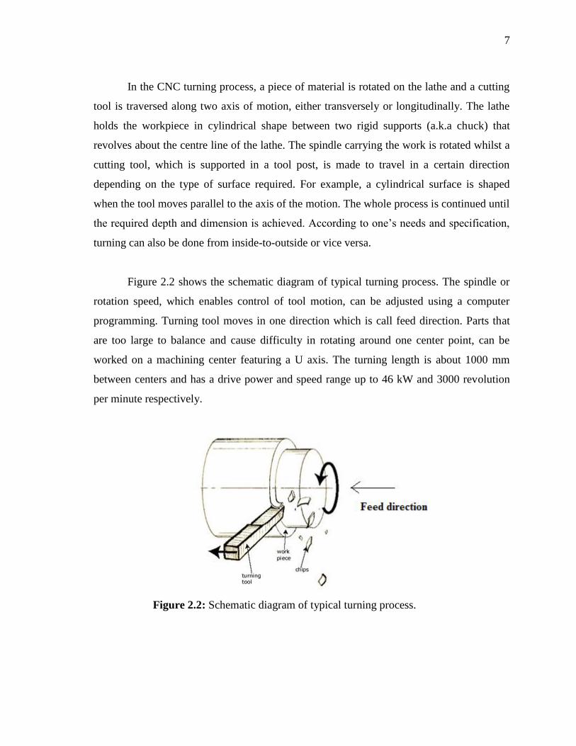
Figure 2.2 shows the schematic diagram of typical turning process. The spindle or
rotation speed, which enables control of tool motion, can be adjusted using a computer
programming. Turning tool moves in one direction which is call feed direction. Parts that
are too large to balance and cause difficulty in rotating around one center point, can be
worked on a machining center featuring a U axis. The turning length is about 1000 mm
between centers and has a drive power and speed range up to 46 kW and 3000 revolution
per minute respectively.
Figure 2.2: Schematic diagram of typical turning process.

8
According to the diagram above, it is necessary to identify the appropriate spindle
rotational speed before running the turning process. Different materials would have
different allowable cutting speed range. The relationship between surface speeds so called
cutting speed and spindle rotational speed can be best described as:
V= DN (1)
Where,
V= Cutting speed, (m/min)
D= Diameter of bar (m)
N= Spindle rotational speed (RPM)
The cutting tool is used until the required depth and dimension is achieved. Turning
can be on both side, inside or outside as per the need and specifications. The rotation occurs
at the turning center that enables control of tool motion through computer programs that
use numeric data.
CNC turning process allows the materials to be cut into various shapes ranging from
plain surface, taper ends, contour and filter to radius profiles as well as threaded surfaces.
These cut and turned metal pieces are then used to create shafts, rods, hubs, bushes, pulley
and etc. CNC turning machines are able to deliver components at a faster production rate
with optimum manufacturing accuracy.
2.4 TURNING PARAMETER
In turning process, the speed and motion of the cutting tool is specified through
several parameters. These parameters are selected for each operation based upon the
workpiece material, tool size, and tool material. These parameters are important because it
will directly affecting the output and also the performance of work. So, the turning
parameters that can affect the process are shown in the Table 2.1.

9
Table 2.1: Parameter in turning process.
Parameter Definition
Cutting speed The speed of the workpiece surface relative to the edge of the
cutting tool during a cut, measured in surface feet per minute
(SFM).
Feed rate The speed of the cutting tool relative to the workpiece as the tool
makes a cut, measured in millimeter per revolution (RPM).
Spindle speed The rotational speed of the workpiece in revolution per minute
(RPM). The spindle speed is equal to the cutting speed divided
by the circumference of the workpiece where the cut is being
made.
Axial depth of cut The depth of the tool along the axis of the workpiece as it makes
a cut, as in a facing operation.
Radial depth of cut The depth of the tool along the radius of the workpiece as it
makes a cut, as in a turning or boring operation. A large radial
depth of cut will require low feed rate, or else it will result in a
high load on the tool and reduce the tool life.
2.5 CUTTING TOOLS
Cutting tool is one of the most important components in the machining process, in
which its performance determines the efficiency of the operation. In particular,
consideration should be given not only to the selection of the cutting tool material but also
to the cutting tool angles required to machine titanium properly.
Generally, the properties possessed by each of these materials are different and the
application of each depends on the material being machined and the condition of the
machine. Different material property would require different cutting tool to shape it into
desire dimension. Generally, these tool bits should possess the following properties: