Embed Size (px)
Citation preview

1
Effect of ash on coal direct chemical looping combustion
Rahul Wadhwani*, Bikash Mohanty
Heat Transfer Research Lab, Department of Chemical Engineering,
Indian Institute of Technology, Roorkee
Roorkee, Uttarakhand, India – 247667
Email: [email protected]
Email: [email protected]
* Corresponding Author
Biographical Note:
Dr. Bikash Mohanty is associated with Department of Chemical Engineering, Indian Institute of
Technology, Roorkee, India as a Professor. He is actively associated in teaching, research and
consulting. He has worked in the fields of multiphase heat transfer, Process simulation and
design, Process Integration and optimization and Fire Engineering. He is also the coordinator of
Education Technology cell which develops NPTEL online courses.
Rahul Wadhwani did his Integrated Dual Degree from Department of Chemical Engineering,
Indian Institute of Technology, Roorkee, India in the year 2014. He works in the field of CFD
simulation, Processes Optimization, etc. At present he is doing his Ph.D. from Centre for Fire
Safety and Risk Engineering, Victoria University, Melbourne, Australia on CFD modeling of
bushfire.
Abstract:
Low ash content coal as a fuel for chemical looping combustion for the production of clean
energy along with CO2 capture has been well established. However, major coal deposits in the
region of Asia-Pacific and Australia are of high ash content and thus, pose difficulties in
utilization of this technology. Therefore, an attempt has been made in the present work to study
chemical looping combustion of high ash coal. For this purpose a CFD model which incorporates
both fuel and air reactors and their inter-connecting parts to simulate a real chemical looping
pilot plant has been developed. The results obtained for sub-bituminous coal as well as
metallurgical coke for the above reactor have been validated against the published data within an

2
error band of 7%-14%. The validated model is then used for two high ash content coals
designated as A and B.
Simulated results show that for A and B, fuel conversions are 93.8% and 87.79% respectively
and that purity of CO2 in air reactor exhaust are 89.12% and 90.73%. It has also been observed
that, components of ash such as CaO, Fe2O3 show significant reactivity at the operating
conditions, whereas, SiO2 exhibits almost negligible reactivity. Further, in case of high ash coal,
due to its low carbon content, the fuel requirement increases to sustain operating conditions.
Keywords: High ash content coal, Chemical looping combustion, CFD simulation
Introduction:
The rising trend of energy usage and amount of CO2 in atmosphere exceeding 400ppm mark has
created an alarming situation and thus provides required impetus for the development of clean
energy processes. Power generation through renewable energy sources like Solar, Wind and
Geothermal appears to be promising; however, it is still a distant dream that these resources can
meet the present energy demand. Further, nuclear energy, due to its constraints related to safety
and spent fuel management, also creates impediment in its development and full use. The
challenges offered by above energy resources are shifting the pressure towards the use of fossil
fuel to meet the recent energy demands though, its depleting quality is a matter of concern and
offering increased challenges in terms of its pre- and post- treatment. [1]-[2]
Further, secured availability of coal for around 200 years and as its cost being marginally
increasing with time unlike other fossil fuels, it appears to be a suitable fuel material for meeting
present and future energy demands. However, as observed by Mauna Loa Observatory, the
recent atmospheric CO2 level has touched an alarming level of 400ppm mark making it
mandatory to develop clean, sustainable energy technologies for coal which can reduce CO2
emission by capturing it in-situ. As chemical looping combustion is one such technology, a
considerable amount of effort has been directed towards the development of this technology.
Chemical looping process produces sequestration ready exhaust gases which mainly comprises
of water and carbon dioxide from which water can be easily separated by the process of
condensation.
3
Various simulation based investigations have been carried out on different segments of the above
process such as a single reactor. One such CFD based study is by Deng et al. [3] on reaction
kinetics of chemical looping combustion for fuel reactor only using FLUENT. They studied the
effect of particle diameter, gas flow rate and bed temperature on fuel conversion. Further, a three
dimensional CFD model for circulating fluidized bed fuel reactor has been developed by Wang
et al. [4] using solid coal as a fuel and ilmenite (FeTiO3) as an oxygen carrier. However, they
have only evaluated the effect of operating variables on the fuel conversion of the fuel reactor.
Furthermore, Wang et al. [5] developed a three dimensional numerical model for reactions
between coal gas as fuel and cuprous oxide on alumina as an oxygen carrier for fuel reactor only
considering kinetic theory of granular flow and analyzed the effects of the operating conditions
such as bed height, bed temperature and operating pressure on fuel conversion. Though,
Kruggel-Emden et al. [6] conducted an interconnected multiphase CFD simulation study of
chemical looping combustion using methane as fuel and Mn3O4 supported on Mg-ZrO2 as
oxygen carrier for two separate systems, where bubbling fluidized bed is used for fuel reactor
and riser as air reactor, their study did not include the interaction between the two reactors. In the
absence of actual interaction study, they considered a time dependent mass exchange between
these two reactors through inlet and outlet boundary conditions only.
Though, a considerable work has been carried out in the field of chemical looping, there appears
to be substantive gap related to CFD based study of the complete process which incorporates the
flow of material through fuel reactor, air reactor and their inter-connecting parts simultaneously
to incorporate interaction between various parts of the process. To bridge the above gap, the
present CFD simulation is carried out for a 25 kWth complete pilot plant developed at Ohio State
University, USA and discussed by Kim et al. [7]. They have discussed and reported the design
criteria and operating conditions of the pilot plant wherein, two fuels namely sub-bituminous
coal (SBC) and metallurgical coke (MC) have been used, one at a time, with iron (III) oxide
supported on alumina as an oxygen carrier. They have considered eleven reactions that are taking
place inside the fuel reactor and air reactor and their inter-connecting parts. A search in this
regard, however shows that, they did not consider a few significant reactions for this purpose and
neglected the effect of ash in the reactions. In the present work the CFD model is first verified
against the reported results of the pilot plant data for the fuels SBC and MC. The model
predicted values of fuel conversions for SBC and MC are 95.39% and 87.07% respectively

4
while; the literature reported values are 97% and 81%. Furthermore, the predicted purities of
CO2 in fuel reactor exhaust streams are 90.19% and 92.57% while; the reported values are 99.8%
and 99.6% respectively for SBC and MC. After the validation of the present model, it is applied
on two coals found in the region of Asia-Pacific and Australia having high ash content
designated as A and B respectively.
2. Problem description:
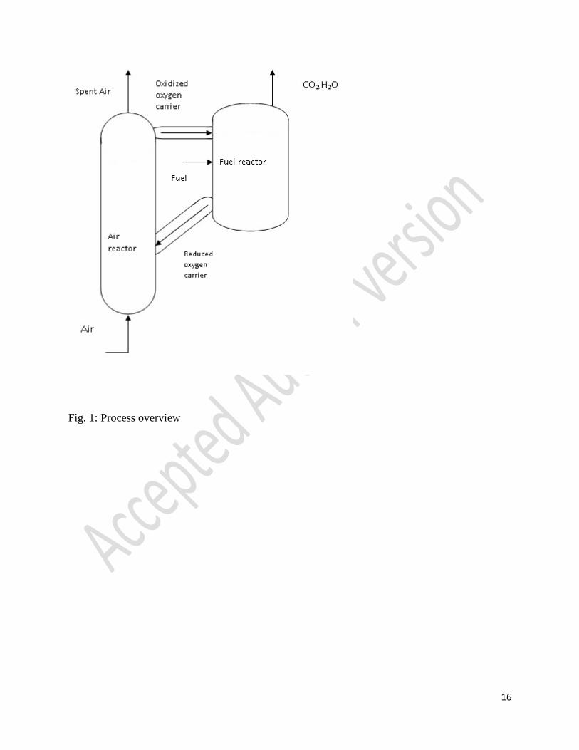
In the chemical looping process, as proposed by Lewis and Gilliland [8], a carbonaceous fuel
like natural gas, methane, coal, biomass, etc. first reacts in a fuel reactor with a metal oxide
oxygen carrier such as iron oxide, nickel oxide, copper oxide, etc.. After reaction, this metal
oxide gets reduced to metal and subsequently oxidizes the carbon present in the carbonaceous
fuel. The above reaction yields carbon dioxide and steam as products from which carbon dioxide
can readily be separated by removing steam through the process of condensation. The reduced
metal received from the fuel reactor is oxidized in the air reactor for its regeneration to metal
oxide, which is then recycled back to the fuel reactor for reuse. The above discussed cyclic
process is shown in Fig. 1.
3. Problem Description:
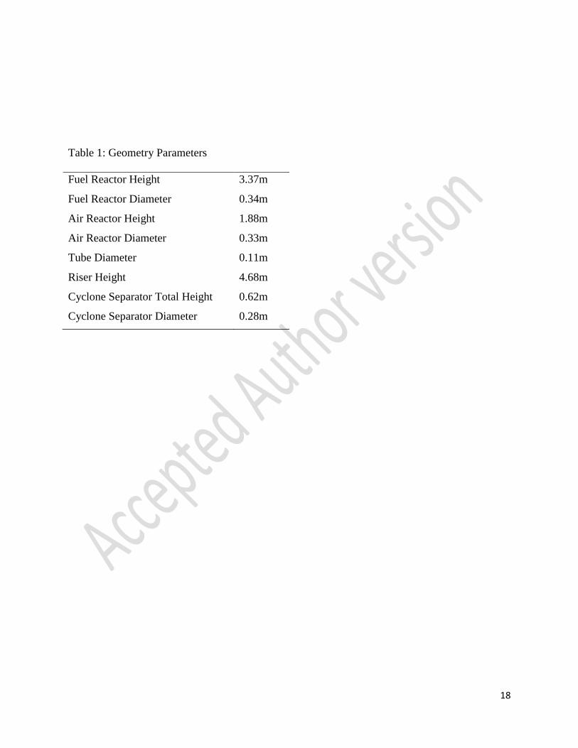
Geometrical parameters of a 25 kWth pilot plant developed by Ohio State University, USA and
described in [7] have been considered for the present CFD simulation. The pilot plant geometry,
taken from the thesis [9], is shown in Fig. 2 with dimension of different section in Table 1. Two
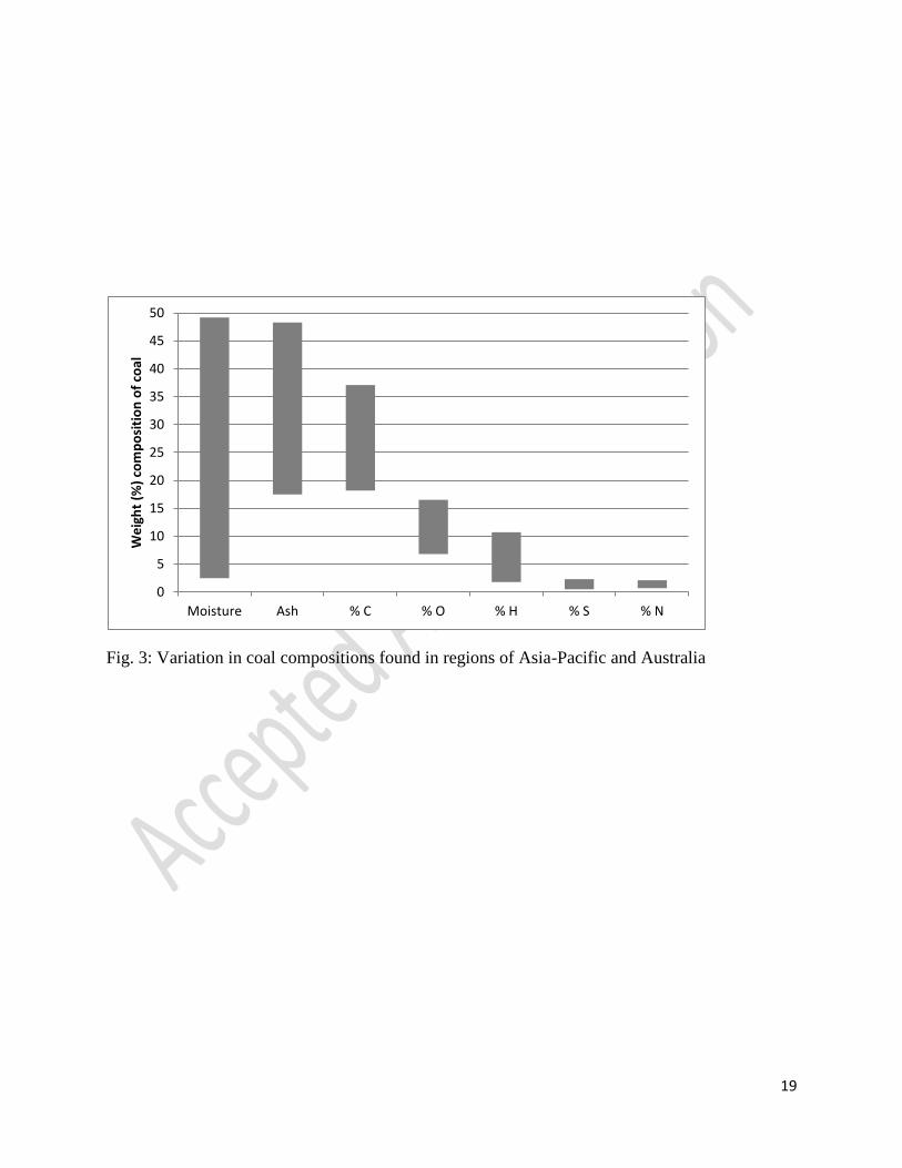
different types of coal namely A and B having high ash contents are used one at a time in the
pilot plant with iron (III) oxide as an oxygen carrier [7]. Both coal samples have been selected in
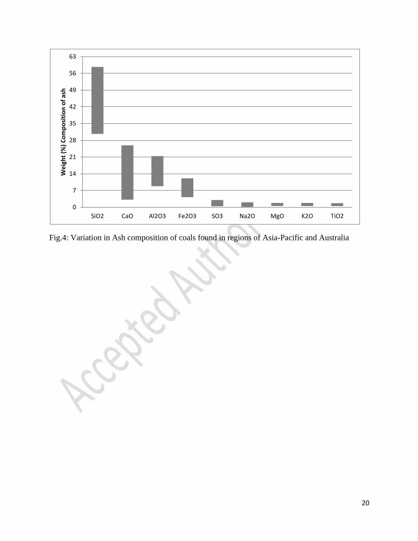
such a way that these depict average composition in the range of compositions for coal and ash
shown in Figs. 3 and 4. These figures cover overall variation in the components of coal found in
the reserves of Asia-Pacific and Australia regions.
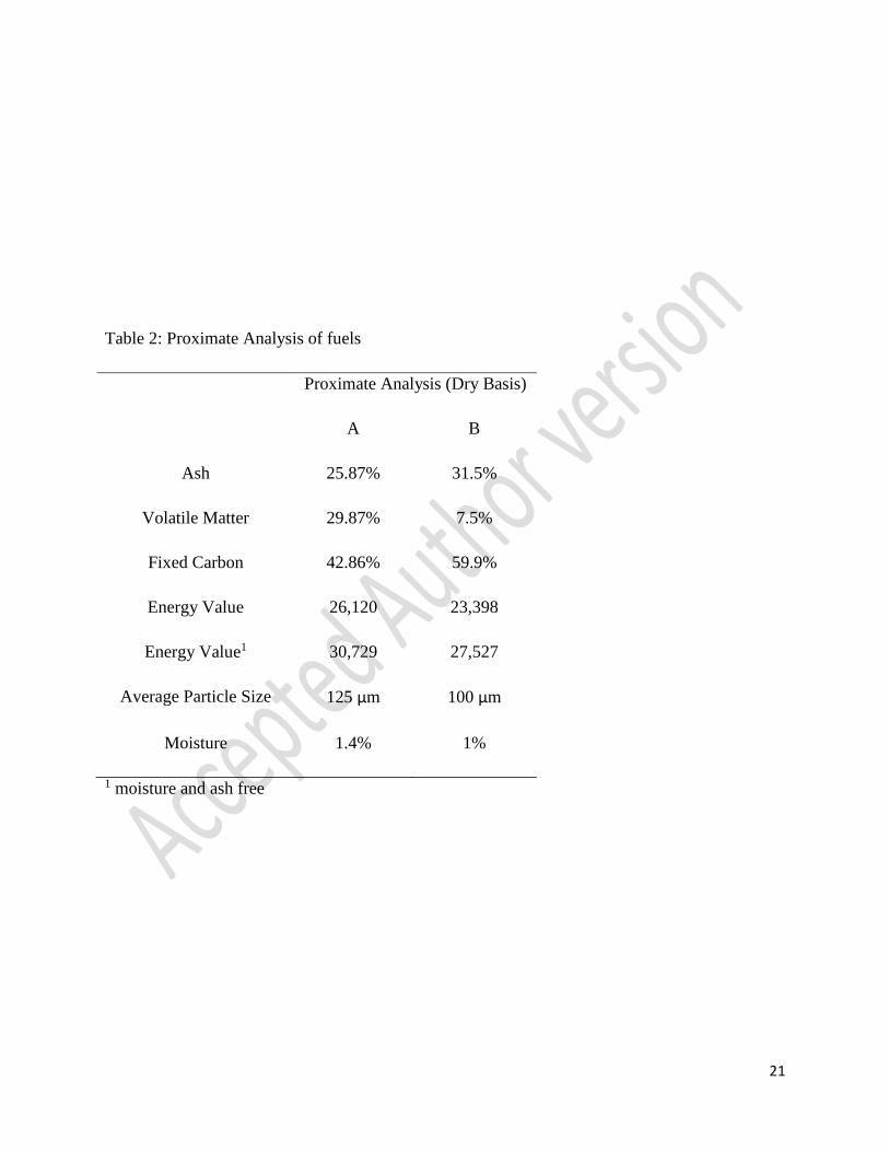
Tables 2 and 3 show the proximate analysis and ultimate analysis (on dry basis) for two coals i.e.
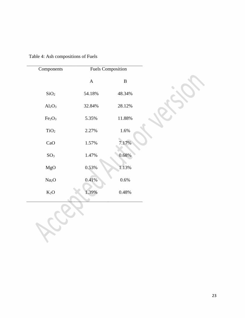
A and B respectively that are used as fuels in the pilot plant described by [7]. Table 4 describes
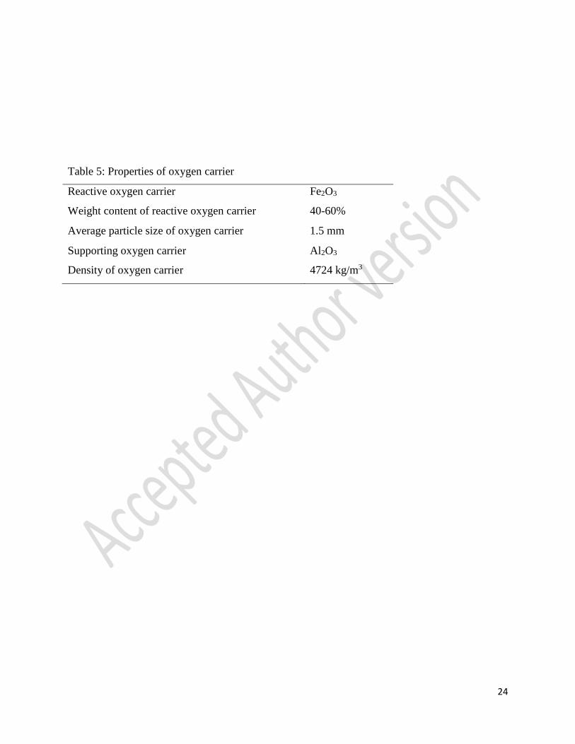
the composition of ash found in the coals used for simulation. Table 5 details properties of
oxygen carrier that has been used for simulation.

5
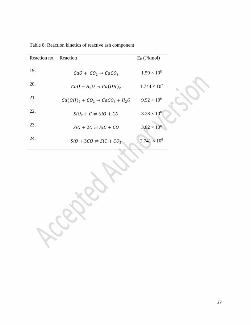
Further, the ash has been classified into two types as reactive ash component and non-reactive
ash component for simulation purpose; the reactive ash component includes SiO2, Fe2O3, CaO
while non-reactive ash components consist of the rest of ash components. Aluminum oxide being
fairly inert is considered as a non-reactive component; while Magnesium oxide and Titanium
dioxide are considered as non-reactive components as well because their presence (wt. %) in ash
is very less (< 3 wt. %). On the other hand, Silica (SiO2) being fairly inert (mass weighted rate of
reaction in the order of 10-22) is taken as a reactive component due to its reasonable presence in
the ash composition.
4. Model Development:
A 2-D CFD model for the inter-connected fuel and air reactor is developed using commercial
computational software Fluent 6.3.2 and mesh for above process layout has been developed
using GAMBIT 2.3.16. The amount of gases injected in the system as well as generated from the
reaction amounts to about 90% by volume. Thus, the gas and the mixture of solids are assumed
to flow as a fluid inside both the reactors and their inter-connecting parts. This assumption has
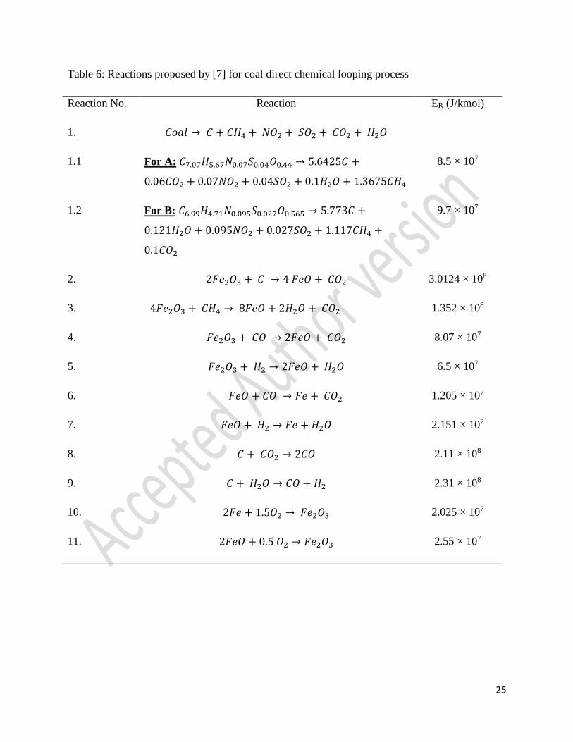
been used for the development of an approximate CFD model. Eleven reactions discussed in [7]
along with 7 other significant reactions plus 6 reactions related to ash (not incorporated by [7]),
as given in Table 6, 7 and 8, respectively are considered for the present CFD simulation. Before
a complicated two phase CFD model is selected for the analysis for the present problem, it is
thought logical to use the least complicated model, the Species-Transport model with volumetric
reaction for the present study to check whether it validates the pilot plant data under acceptable
error limits or not. Following governing equations are solved on commercially available software
Fluent 6.3.2 for the present model:
Mass Conservation Equation:
The equation for mass conservation/continuity equation valid for compressible and
incompressible flows can be written as:
𝜕𝜌
𝜕𝑡+ ∇. (𝜌��) = 𝑆𝑚 ..(1)
Momentum Conservation Equations:

6
In an inertial frame, the momentum conservation equation is described as below Eq. 2:
𝜕(𝜌��)
𝜕𝑡+ ∇. (𝜌����) = −∇𝑝 + ∇. (𝜏) + 𝜌�� + �� ..(2)
The stress tensor 𝜏 is given by Eq. 3
𝜏 = 𝜇 [(∇�� + ∇��𝑇) −2
3∇. ��𝐼] ..(3)
The second term on the right hand side of Eq. 3 is the effect of volume dilation.
Energy Conservation Equation:
The conservation of Energy is defined by the following Eq. 4:
𝜕(𝜌𝐸)
𝜕𝑡+ ∇. (��(𝜌𝐸 + 𝑝)) = ∇. (𝑘𝑒𝑓𝑓∇𝑇 − ∑ ℎ𝑗𝐽𝑗𝑗 + (𝜏��𝑓𝑓. ��)) + 𝑆ℎ ..(4)
𝐸 = ℎ −𝑝
𝜌+
𝑣2
2 ..(5)
Species Transport Equations:
The local mass fraction of each species (Yi) through the solution of a convection-diffusion
equation for the ith species is solved. It takes the following general form:
𝜕
𝜕𝑡(𝜌𝑌𝑖) + ∇. (𝜌��𝑌𝑖) = −∇. 𝐽𝑖
+ 𝑅𝑖 + 𝑆𝑖 ..(6)
Mass Diffusion in Laminar Flows:
In the above Eq. 6, this arises due to concentration gradients. In the present model, dilute
approximation is assumed, under which it is defined as follows:
𝐽𝑖 = −𝜌𝐷𝑖,𝑚∇𝑌𝑖 ..(7)
The Laminar Finite-Rate Model:
The net source of chemical species ith due to reaction is computed as the sum of the Arrhenius
reaction sources over the NR reactions that the species participate in:
7
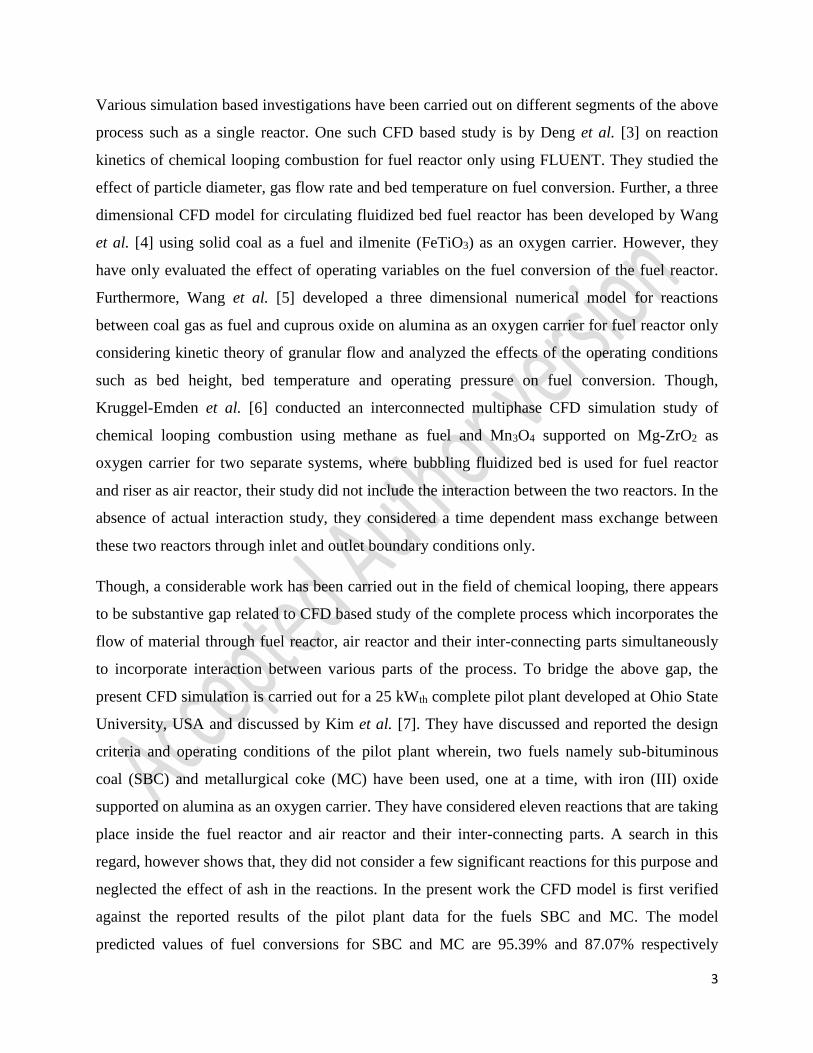
𝑅𝑖 = 𝑀𝑤,𝑖 ∑ 𝑅𝑖,��𝑁𝑅𝑟=1 ..(8)
Consider the rth reaction written in general form as follows in Eq. 9 which is valid for both
reversible and non reversible reactions. For non-reversible reactions the backward rate constant
is omitted.
∑ 𝑣𝑖,𝑟′𝑁
𝑖=1 𝑀𝑖 ⇌ 𝑘𝑏,𝑟
𝑘𝑓,𝑟 ∑ 𝑣𝑖,𝑟′′𝑁
𝑖=1 𝑀𝑖 ..(9)
For a non-reversible reaction, the molar rate of creation/destruction of specie i in
reaction r (𝐑𝐢,��in Eq. 8) is given by,
𝑅𝑖,�� = Γ(𝑣𝑖,𝑟" − 𝑣𝑖,𝑟
′ ) (𝑘𝑓,𝑟 ∏ [𝐶𝑗,𝑟](𝜂𝑗,𝑟
′ +𝜂𝑗,𝑟" )𝑁
𝑗=1 ) .. (10)
For a reversible reaction, the molar rate of creation/destruction of species i in reaction r, is given
by,
𝑅𝑖,�� = Γ(𝑣𝑖,𝑟" − 𝑣𝑖,𝑟
′ ) (𝑘𝑓,𝑟 ∏ [𝐶𝑗,𝑟]𝜂𝑗,𝑟
′𝑁𝑗=1 − 𝑘𝑏,𝑟 ∏ [𝐶𝑗,𝑟]
𝑣𝑗,𝑟′′
𝑁𝑗=1 ) ..(11)
The forward rate constant kf,r for reaction r, is computed using the Arrhenius expression
𝑘𝑓,𝑟 = 𝐴𝑟𝑇𝛽𝑟𝑒−𝐸𝑅
𝑅𝑇⁄ ..(12)
Values of v’i,r , v”i,r , η’j,r ,η”j,r , βr ,Ar and ER are provided to solve Eq. 10
For reversible reactions, the backward rate constant kb,r for reaction r, is computed from the
forward rate constant using the following relation:
𝑘𝑏,𝑟 =𝑘𝑓,𝑟
𝐾𝑟 ..(13)
The value of Kr is computed from the following Eq. 14
𝐾𝑟 = 𝑒(
Δ𝑆𝑟0
𝑅 −
Δ𝐻𝑟0
𝑅𝑇)
(𝑝𝑎𝑡𝑚
𝑅𝑇)
∑ (𝑣𝑖,𝑟′′ −𝑣𝑖,𝑟
′ )𝑁𝑖=1
..(14)

8
Where, the term within the exponential function represents the change in Gibbs free energy, and
its components are computed as follows:
Δ𝑆𝑟0
𝑅= ∑ (𝑣𝑖,𝑟
′′ − 𝑣𝑖,𝑟′ )𝑁
𝑖=1𝑆𝑖
0
𝑅 ..(15)
∆𝐻𝑟0
𝑅𝑇= ∑ (𝑣𝑖,𝑟
′′ − 𝑣𝑖,𝑟′ )
ℎ𝑖0
𝑅𝑇
𝑁𝑖=1 ..(16)
Reactions Kinetics:
The present study is carried out for two types of coal A, and B; it utilizes 24 reactions for the
process which are taking place inside two reactors and their inter-connecting parts. In Table 6,
11, reactions proposed by [7] are described while, in Tables 7 and 8, other seven significant
reactions and reactions pertaining to reactive ash components with their kinetics are tabulated.
Standard k-ε turbulence model:
The standard k-ε turbulence model described by Launder and Spalding in 1974 is used for the
present study.
Eq. 17 is described for turbulent kinetic energy k
𝜕(𝜌𝑘)
𝜕𝑡+
𝜕(𝜌𝑘𝑢𝑖)
𝜕𝑥𝑖=
𝜕
𝜕𝑥𝑖[(𝜇 +
𝜇𝑡
𝜎𝑘)
𝜕𝑘
𝜕𝑥𝑗] + 𝐺𝑘 + 𝐺𝑏 − 𝜌𝜖 − 𝑌𝑀 + 𝑆𝑘 ..(17)
And Eq. 18 is described for the rate of dissipation ε
𝜕(𝜌 )
𝜕𝑡+
𝜕(𝜌 𝑢𝑖)
𝜕𝑥𝑖=
𝜕
𝜕𝑥𝑖[(𝜇 +
𝜇𝑡
𝜎𝑘)
𝜕
𝛿𝑥𝑗] + 𝐶1 𝑘
(𝐺𝑘 + 𝐶3 𝐺𝑏) − 𝐶2 𝜌2
𝑘+ 𝑆 ..(18)
Where, Gk is calculated by Eq. 19, Gb is calculated by Eq. 20, YM is calculated by Eq. 21
C1ε, C2ε, C3ε are the constants (C1ε = 1.44, C2ε =1.92)
σk =1, σε =1.3
𝐺𝑘 = −𝜌𝑢𝑖′𝑢𝑗
′ 𝜕𝑢𝑗
𝜕𝑥𝑖 ..(19)

9
𝐺𝑏 = 𝛽𝑔𝑖𝜇𝑡
𝑃𝑟𝑡
𝜕𝑇
𝜕𝑥𝑖 ..(20)
Where, Prt = 0.85
𝑌𝑀 = 2𝜌𝜀𝑀𝑡2 ..(21)
𝑀𝑡 = √𝑘
𝑎2 and 𝑎 = √𝛾𝑅𝑇
Mass-weighted average of rate of reaction:
The mass-weighted average of rate of reaction in different sections are computed by dividing, the
summation of the values of the rate of reaction multiplied by the absolute value of the dot
product of the facet area and momentum vectors, by the summation of the absolute value of the
dot product of the facet area and momentum vectors as given in Eq.22:
∫ 𝑅�� 𝜌|��.𝑑��|
∫ 𝜌|��.𝑑��|=
∑ 𝑅𝑖,��𝜌𝑖|𝑣𝑖 .𝐴𝑖|𝑛𝑖=1
∑ 𝜌𝑖|𝑣𝑖 .𝐴𝑖|𝑛𝑖=1
..(22)
5. Solution Technique:
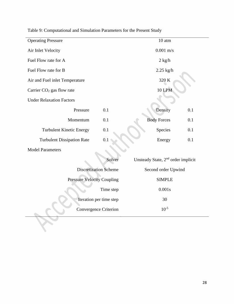
In this section, solution technique adopted for the present study is described. The pilot plant
dimensions are taken from the mechanical drawing of the pilot plant described in [7]. The
boundary condition for air and coal inlets are defined as velocity inlet and mass flow inlet, while,
fuel reactor and cyclone exhausts are defined as pressure outlets. Unsteady state simulations are
carried out for present study and a time step of 0.001s is chosen for mesh grid size of 0.01(m)
obtained from grid independence test for MC during model verification. The computational
parameters used in present study are discussed in Table 9.
6. Result and Discussion:
In this section, the results obtained from the study of the effect of ash components present in
coal during coal direct chemical looping combustion using the validated 2-D CFD model
developed in present study is discussed. The previously developed model incorporating eighteen
reactions for MC and SBC showed a better agreement with the pilot plant data. In present study
only reaction kinetic aspect of ash is studied, the melting of ash and its associated effects, oxygen
10
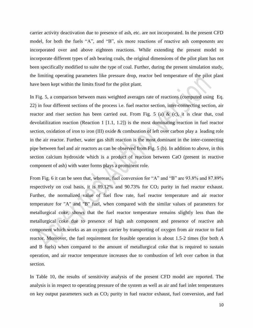
carrier activity deactivation due to presence of ash, etc. are not incorporated. In the present CFD
model, for both the fuels “A”, and “B”, six more reactions of reactive ash components are
incorporated over and above eighteen reactions. While extending the present model to
incorporate different types of ash bearing coals, the original dimensions of the pilot plant has not
been specifically modified to suite the type of coal. Further, during the present simulation study,
the limiting operating parameters like pressure drop, reactor bed temperature of the pilot plant
have been kept within the limits fixed for the pilot plant.
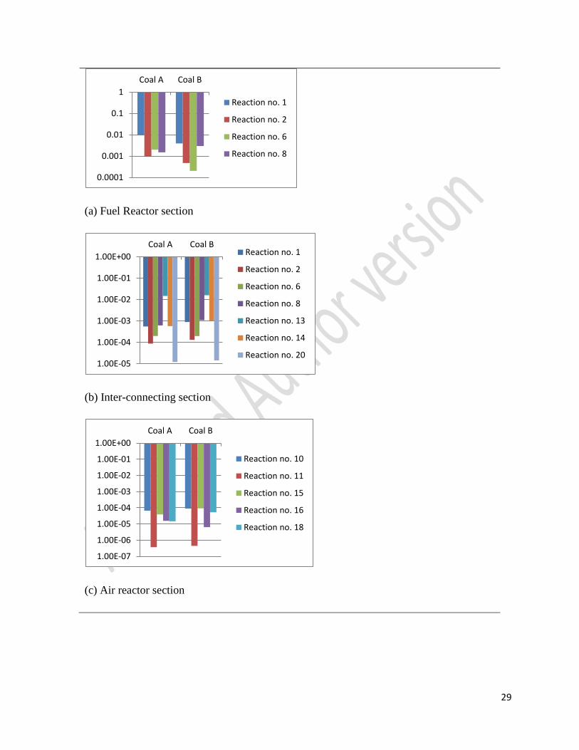
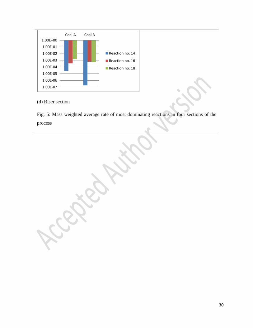
In Fig. 5, a comparison between mass weighted averages rate of reactions (computed using Eq.
22) in four different sections of the process i.e. fuel reactor section, inter-connecting section, air
reactor and riser section has been carried out. From Fig. 5 (a) & (c), it is clear that, coal
devolatilization reaction (Reaction 1 [1.1, 1.2]) is the most dominating reaction in fuel reactor
section, oxidation of iron to iron (III) oxide & combustion of left over carbon play a leading role
in the air reactor. Further, water gas shift reaction is the most dominant in the inter-connecting
pipe between fuel and air reactors as can be observed from Fig. 5 (b). In addition to above, in this
section calcium hydroxide which is a product of reaction between CaO (present in reactive
component of ash) with water forms plays a prominent role.
From Fig. 6 it can be seen that, whereas, fuel conversion for “A” and “B” are 93.8% and 87.89%
respectively on coal basis, it is 89.12% and 90.73% for CO2 purity in fuel reactor exhaust.
Further, the normalized value of fuel flow rate, fuel reactor temperature and air reactor
temperature for "A" and "B" fuel, when compared with the similar values of parameters for
metallurgical coke, shows that the fuel reactor temperature remains slightly less than the
metallurgical coke due to presence of high ash component and presence of reactive ash
component which works as an oxygen carrier by transporting of oxygen from air reactor to fuel
reactor. Moreover, the fuel requirement for feasible operation is about 1.5-2 times (for both A
and B fuels) when compared to the amount of metallurgical coke that is required to sustain
operation, and air reactor temperature increases due to combustion of left over carbon in that
section.
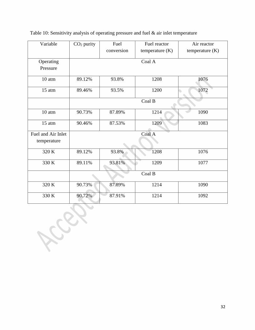
In Table 10, the results of sensitivity analysis of the present CFD model are reported. The
analysis is in respect to operating pressure of the system as well as air and fuel inlet temperatures
on key output parameters such as CO2 purity in fuel reactor exhaust, fuel conversion, and fuel

11
and air reactor temperature. It can be seen that the sensitivity of system for change in operating
pressure is significant while, sensitivity for fuel and air inlet temperature is almost negligible.
7. Conclusion:
In present study, following salient features are observed:
1. Fuel conversion on dry ash free basis for fuel coals “A” and “B” are 93.8% and 90.73%
respectively.
2. CaO and Fe2O3 as a part of reactive ash component shows reactivity under the process
condition while SiO2 exhibits a mass weighted average rate of reactions which is less
than 10-20 kmol/m3-s indicating that it works almost as an inert material.
3. The amount of ash present in fuel coal increases its fuel flow rate proportionately to
maintain required feasible process conditions for chemical looping combustion. The
carbon capturing efficiency decreases as fuel flow rate is increased. This observation is in
conformity to Abad et al. [10]. Further, it can be seen that overall fuel conversion
decreases as amount of non-carbonaceous species increases such as moisture and ash in
the fuel coal as also been identified by Azis et al. [11]
4. The carbon dioxide purity in fuel reactor exhaust increases with the rise in fuel reactor
temperature for the two fuels used in the present study. This fact is in tune with the
observations of Abad et al. [10] carried out for El Cerrejόn coal with less than 10% ash
content.
8. Nomenclature
Ar pre-exponential factor
β coefficient of thermal expansion
βr temperature exponent
12
Cj,r molar concentration of species j in reaction r
Di,m diffusion coefficient for the ith species in the mixture
ε the rate of dissipation
ER activation energy for the reaction
�� external body forces and also contains user-defined terms
γj,r third-body efficiency of the jth species in the rth reaction
gi gravitational vector in the ith direction
Gb the generation of turbulence kinetic energy due to buoyancy
Gk generation of turbulence kinetic energy due to mean velocity gradients
h0i standard-state enthalpy (heat of formation) which are specified as properties for
every species
I unit tensor
𝐽𝑖 diffusion flux of the ith species,
𝐽𝑗 diffusion flux of species j
K turbulent kinetic energy
kb,r backward rate constant for reaction r
keff effective conductive (=k+kt)
kf,r forward rate constant for reaction r
kt turbulent thermal conductivity
Kr equilibrium constant for the rth reaction
Μ molecular viscosity
μt turbulent viscosity
Mi symbol denoting species i
Mt turbulent Mach number
Mw,i molecular weight of ith species
η'j,r rate exponent for reactant species j in reaction r
η”j,r rate exponent for product species j in reaction r
13
N number of chemical species in the system
P static pressure
patm atmospheric pressure (101.325 kPa)
Prt turbulent Prandtl number for energy
𝜌�� gravitational body force
R universal gas constant
Ri net rate of production of species i by chemical reaction
𝐑𝐢,�� Arrhenius molar rate of creation/destruction of species ith in reaction r
σε turbulent Prandtl number for ε
σk turbulent Prandtl number for k
Sε User defined source term
Sh the heat of chemical reaction and any other volumetric source by user defined
function
Si rate of creation by addition from dispersed phase plus any user defined sources
S0i standard-state entropy which are specified as properties for every species
Sk User defined source term
Sm mass added to continuous phase from second phase or any user-defined sources
𝜏 stress tensor
Γ the net effect of third bodies on the reaction rate
v’i,r stoichiometric coefficient for reactant i in reaction r
v”i,r stoichiometric coefficient for product i in reaction r
Yj the mass fraction of species j
YM the contribution of the fluctuating dilation in compressible turbulence to the overall
dissipation rate
9. References:
14
[1] BP Statistical Review of World Energy, June 2013
[2] Energy Information Administration, “International Energy Outlook 2006”, U.S. Department
of Energy, Washington DC, 2006
[3] Zhongyi Deng, Rui Xiao, Baosheng Jin, Qilei Song, He Huang, “Multiphase CFD Modeling
for a Chemical Looping Combustion Process (Fuel Reactor)”, Chemical Engineering
Technology, Vol. 31, Issue 12, 2008, pp.1754-1766
[4] Xiaojia Wang, Baosheng Jin, Yong Zhang, Yi Zhang, Xianli Liu, “Three Dimensional
Modeling of a Coal-Fired Chemical Looping Combustion Process in the Circulating Fluidized
Bed Fuel Reactor”, Energy & Fuels, Vol. 27, 2013, pp. 2173-2184
[5] Xiaojia Wang, Baosheng Jin, Yong Zhang, Wenqi Zhong, Shangyi Yin, “Multiphase
Computational Fluid Dynamics (CFD) modeling of chemical looping combustion using a
CuO/Al2O3 oxygen carrier: effect of operating conditions on coal gas combustion”, Energy &
Fuels, Vol. 25, 2011, pp. 3815-3824
[6] H. Kruggel-Emden, S.Rickelt, F.Stepanek, A.Munjiza, “Development and testing of an
interconnected multiphase CFD-model for chemical looping combustion”, Chemical Engineering
Sciences, Vol. 65, 2010, pp. 4732-4745
[7] Hyung R. Kim, Dawei Wang, Liang Zeng, Samuel Bayham, Andrew Tong, Elena Chung,
Mandar V. Kathe, Siwei Luo, Omar McGiveron, Aining Wang, Zhenchao Sun, David Chen,
Liang-Shih Fan, “Coal direct chemical looping combustion process: Design and operation of a
25-kWth sub-pilot unit”, Fuel, Vol. 108, 2013, pp. 370-384
[8] L.S. Fan, Chemical looping systems for fossil energy conversion, A John Wiley & sons Inc.,
publication, 2010
[9] Rahul Wadhwani, “CFD study of a coal direct chemical looping pilot plant”, IDD Thesis,
Indian Institute of Technology Roorkee, Roorkee, India, 2014
[10] A. Abad, J. Adánez, L. F. de Deigo, P. Gayán, F. G. Labiano, A. Lyngfelt, “Fuel reactor
model validation: Assessment of the key parameters affecting the chemical looping combustion
of coal”, International Journal of Greenhouse Gas Control, Vol. 19, 2013, pp. 541- 551

15
[11] M. M. Azis, H. Leion, E. Jerndal, B. M. Steenari, T. Mattison, A. Lyngfelt, “The effect of
bituminous and lignite ash on the performance of ilmenite as oxygen carrier in chemical looping
combustion”, Chemical Engineering Technology, Vol. 36, 2013, pp. 1460-1468
16
Fig. 1: Process overview

17
Fig. 2: Pilot plant of present problem
18
Table 1: Geometry Parameters
Fuel Reactor Height 3.37m
Fuel Reactor Diameter 0.34m
Air Reactor Height 1.88m
Air Reactor Diameter 0.33m
Tube Diameter 0.11m
Riser Height 4.68m
Cyclone Separator Total Height 0.62m
Cyclone Separator Diameter 0.28m
19
Fig. 3: Variation in coal compositions found in regions of Asia-Pacific and Australia
0
5
10
15
20
25
30
35
40
45
50
Moisture Ash % C % O % H % S % N
We
igh
t (%
) co
mp
osi
tio
n o
f co
al
20
Fig.4: Variation in Ash composition of coals found in regions of Asia-Pacific and Australia
0
7
14
21
28
35
42
49
56
63
SiO2 CaO Al2O3 Fe2O3 SO3 Na2O MgO K2O TiO2
We
igh
t (%
) C
om
po
siti
on
of
ash
21
Table 2: Proximate Analysis of fuels
Proximate Analysis (Dry Basis)
A B
Ash 25.87% 31.5%
Volatile Matter 29.87% 7.5%
Fixed Carbon 42.86% 59.9%
Energy Value 26,120 23,398
Energy Value1 30,729 27,527
Average Particle Size 125 μm 100 μm
Moisture 1.4% 1%
1 moisture and ash free

22
Table 3: Ultimate Analysis of fuels
Ultimate Analysis (Dry Basis)
A B
Carbon 61.76% 56.7%
Hydrogen 4.16% 3.2%
Nitrogen 0.76% 0.9%
Sulfur 0.91% 0.6%
Oxygen 5.14% 6.1%
23
Table 4: Ash compositions of Fuels
Components Fuels Composition
A B
SiO2 54.18% 48.34%
Al2O3 32.84% 28.12%
Fe2O3 5.35% 11.88%
TiO2 2.27% 1.6%
CaO 1.57% 7.17%
SO3 1.47% 0.68%
MgO 0.53% 1.13%
Na2O 0.41% 0.6%
K2O 1.39% 0.48%
24
Table 5: Properties of oxygen carrier
Reactive oxygen carrier Fe2O3
Weight content of reactive oxygen carrier 40-60%
Average particle size of oxygen carrier 1.5 mm
Supporting oxygen carrier Al2O3
Density of oxygen carrier 4724 kg/m3
25
Table 6: Reactions proposed by [7] for coal direct chemical looping process
Reaction No. Reaction ER (J/kmol)
1. 𝐶𝑜𝑎𝑙 → 𝐶 + 𝐶𝐻4 + 𝑁𝑂2 + 𝑆𝑂2 + 𝐶𝑂2 + 𝐻2𝑂
1.1 For A: 𝐶7.07𝐻5.67𝑁0.07𝑆0.04𝑂0.44 → 5.6425𝐶 +
0.06𝐶𝑂2 + 0.07𝑁𝑂2 + 0.04𝑆𝑂2 + 0.1𝐻2𝑂 + 1.3675𝐶𝐻4
8.5 × 10⁷
1.2 For B: 𝐶6.99𝐻4.71𝑁0.095𝑆0.027𝑂0.565 → 5.773𝐶 +
0.121𝐻2𝑂 + 0.095𝑁𝑂2 + 0.027𝑆𝑂2 + 1.117𝐶𝐻4 +
0.1𝐶𝑂2
9.7 × 10⁷
2. 2𝐹𝑒2𝑂3 + 𝐶 → 4 𝐹𝑒𝑂 + 𝐶𝑂2 3.0124 × 10⁸
3. 4𝐹𝑒2𝑂3 + 𝐶𝐻4 → 8𝐹𝑒𝑂 + 2𝐻2𝑂 + 𝐶𝑂2 1.352 × 10⁸
4. 𝐹𝑒2𝑂3 + 𝐶𝑂 → 2𝐹𝑒𝑂 + 𝐶𝑂2 8.07 × 10⁷
5. 𝐹𝑒2𝑂3 + 𝐻2 → 2𝐹𝑒𝑂 + 𝐻2𝑂 6.5 × 10⁷
6. 𝐹𝑒𝑂 + 𝐶𝑂 → 𝐹𝑒 + 𝐶𝑂2 1.205 × 10⁷
7. 𝐹𝑒𝑂 + 𝐻2 → 𝐹𝑒 + 𝐻2𝑂 2.151 × 10⁷
8. 𝐶 + 𝐶𝑂2 → 2𝐶𝑂 2.11 × 10⁸
9. 𝐶 + 𝐻2𝑂 → 𝐶𝑂 + 𝐻2 2.31 × 10⁸
10. 2𝐹𝑒 + 1.5𝑂2 → 𝐹𝑒2𝑂3 2.025 × 10⁷
11. 2𝐹𝑒𝑂 + 0.5 𝑂2 → 𝐹𝑒2𝑂3 2.55 × 10⁷

26
Table 7: Other significant reactions for coal direct chemical looping process
Reaction No. Reaction ER (J/kmol)
12. 𝐶 + 2𝐻2 → 𝐶𝐻4 1.5 × 10⁸
13. 𝐶𝑂 + 𝐻2𝑂 ⇌ 𝐶𝑂2 + 𝐻2 1.26 × 10⁷
14. 𝐶𝐻4 + 𝐻2𝑂 ⇌ 𝐶𝑂 + 3𝐻2 3 × 10⁷
15. 𝐶 + 𝑂2 → 𝐶𝑂2 1.794 × 10⁸
16. 𝐶𝑂 + 0.5 𝑂2 → 𝐶𝑂2 1.674 × 10⁸
17. 2𝐹𝑒𝑂 + 𝐻2𝑂 → 𝐹𝑒2𝑂3 + 𝐻2 7.79 × 10⁷
18. 2𝐻2 + 𝑂2 → 2𝐻2𝑂 2.852 × 10⁷
27
Table 8: Reaction kinetics of reactive ash component
Reaction no. Reaction ER (J/kmol)
19. 𝐶𝑎𝑂 + 𝐶𝑂2 → 𝐶𝑎𝐶𝑂3 1.59 × 10⁸
20. 𝐶𝑎𝑂 + 𝐻2𝑂 → 𝐶𝑎(𝑂𝐻)2 1.744 × 10⁷
21. 𝐶𝑎(𝑂𝐻)2 + 𝐶𝑂2 → 𝐶𝑎𝐶𝑂3 + 𝐻2𝑂 9.92 × 10⁶
22. 𝑆𝑖𝑂2 + 𝐶 ⇌ 𝑆𝑖𝑂 + 𝐶𝑂 3.28 × 10⁸
23. 𝑆𝑖𝑂 + 2𝐶 ⇌ 𝑆𝑖𝐶 + 𝐶𝑂 3.82 × 10⁸
24. 𝑆𝑖𝑂 + 3𝐶𝑂 ⇌ 𝑆𝑖𝐶 + 𝐶𝑂2 2.741 × 10⁸
28
Table 9: Computational and Simulation Parameters for the Present Study
Operating Pressure 10 atm
Air Inlet Velocity 0.001 m/s
Fuel Flow rate for A 2 kg/h
Fuel Flow rate for B 2.25 kg/h
Air and Fuel inlet Temperature 320 K
Carrier CO2 gas flow rate 10 LPM
Under Relaxation Factors
Pressure 0.1 Density 0.1
Momentum 0.1 Body Forces 0.1
Turbulent Kinetic Energy 0.1 Species 0.1
Turbulent Dissipation Rate 0.1 Energy 0.1
Model Parameters
Solver Unsteady State, 2nd order implicit
Discretization Scheme Second order Upwind
Pressure Velocity Coupling SIMPLE
Time step 0.001s
Iteration per time step 30
Convergence Criterion 10-5
29
(a) Fuel Reactor section
(b) Inter-connecting section
(c) Air reactor section
0.0001
0.001
0.01
0.1
1
Coal A Coal B
Reaction no. 1
Reaction no. 2
Reaction no. 6
Reaction no. 8
1.00E-05
1.00E-04
1.00E-03
1.00E-02
1.00E-01
1.00E+00
Coal A Coal BReaction no. 1
Reaction no. 2
Reaction no. 6
Reaction no. 8
Reaction no. 13
Reaction no. 14
Reaction no. 20
1.00E-07
1.00E-06
1.00E-05
1.00E-04
1.00E-03
1.00E-02
1.00E-01
1.00E+00
Coal A Coal B
Reaction no. 10
Reaction no. 11
Reaction no. 15
Reaction no. 16
Reaction no. 18
30
(d) Riser section
Fig. 5: Mass weighted average rate of most dominating reactions in four sections of the
process
1.00E-07
1.00E-06
1.00E-05
1.00E-04
1.00E-03
1.00E-02
1.00E-01
1.00E+00
Coal A Coal B
Reaction no. 14
Reaction no. 16
Reaction no. 18

31
Fig. 6: Comparative results for coal “A” and “B”
0
0.5
1
1.5
2
Fuel
Conversion
CO2 purity Normalized
Fuel Flow
rate
Normalized
Fuel reactor
temperature
Normalized
air reactor
temperature
Coal "A"
Coal "B"
32
Table 10: Sensitivity analysis of operating pressure and fuel & air inlet temperature
Variable CO2 purity Fuel
conversion
Fuel reactor
temperature (K)
Air reactor
temperature (K)
Operating
Pressure
Coal A
10 atm 89.12% 93.8% 1208 1076
15 atm 89.46% 93.5% 1200 1072
Coal B
10 atm 90.73% 87.89% 1214 1090
15 atm 90.46% 87.53% 1209 1083
Fuel and Air Inlet
temperature
Coal A
320 K 89.12% 93.8% 1208 1076
330 K 89.11% 93.81% 1209 1077
Coal B
320 K 90.73% 87.89% 1214 1090
330 K 90.72% 87.91% 1214 1092