Embed Size (px)
Citation preview
http://www.iaeme.com/IJMET/index.asp 178 [email protected]
International Journal of Mechanical Engineering and Technology (IJMET) Volume 8, Issue 1, January 2017, pp. 178–188, Article ID: IJMET_08_01_020
Available online at http://www.iaeme.com/IJMET/issues.asp?JType=IJMET&VType=8&IType=1
ISSN Print: 0976-6340 and ISSN Online: 0976-6359
© IAEME Publication
EFFECT OF A TIP CLEARANCE ON THE
PERFORMANCE OF A LOW SPEED CENTRIFUGAL
COMPRESSOR
S.M. Swamy
Assistant Professor, Department of Mechanical Engineering,
GNITS, Shaikpet, Hyderabad, India
V. Panndurangadu
Professor, Department of Mechanical Engineering,
JNTUA, Ananthapuramu, A.P, India
J.M. Shamkumar
Design Engineer, Airframe Aero designs Pvt. Ltd., Bangaluru, India
ABSTRACT
Tip clearance effects on flow field of a low speed centrifugal compressor without and with
partial shroud (PS) attached to the rotor blade tip at three values of tip clearance, viz. φ =2.2%,
5.1% and 7.9% of rotor blade height at the exit at three flow coefficients, namely, φ=0.12,0.18
(below design flow coefficient), φ=0.28 (design flow coefficient) and φ=0.34 (above design flow
coefficient), is analysed computationally using structured multi block grid with fine grid in the tip
clearance region. The paper aims to study several flow characteristics between blade channels
using commercial flow solver ANSYS CFX 15.0 based on finite volume techniques. The centrifugal
compressor in aerodynamic requirement is that edge velocities along the impeller channel passage
surfaces like hub, shroud, pressure and suction surfaces vary smoothly without sudden
decelerations, which cause flow separation leading to losses. Using the periodic boundaries and
defined flow conditions at inflow / exit flow and blade rotations, the turbulent viscous flow between
blade channels are computed. The efficiency related parameters using average quantities, besides
flow pattern in terms of velocities, streamlines and pressure distribution on blade surfaces are
graphically interpreted. An attempt is also made to study the influence of pressure loads on
structural deformations in the chosen blade profile. This paper highlights aero-mechanical features
of centrifugal impeller obtained from several numerical simulations, which are expected to provide
a sound basis for further investigations.
Key words: Centrifugal compressor, Flow coefficient, Partial shroud attached to the rotor blade tip,
Streamlines, passage wake.
Cite this Article: S.M. Swamy, V. Panndurangadu and J.M. Shamkumar. Effect of a Tip Clearance
on the Performance of a Low Speed Centrifugal Compressor. International Journal of Mechanical
Engineering and Technology, 8(1), 2017, pp. 178–188.
http://www.iaeme.com/IJMET/issues.asp?JType=IJMET&VType=8&IType=1
Effect of a Tip Clearance on the Performance of a Low Speed Centrifugal Compressor
http://www.iaeme.com/IJMET/index.
1. INTRODUCTION
The centrifugal compressors have a wide range of applications especially for power plants for small
aircraft and helicopters, in process industries, compression of gases and vapours, because they can provide
high-pressure ratios and large operating ranges
are used primarily for their suitability for handling small volume flows, but other advantages include a
shorter length than an equivalent axial flow compressor, less susceptibility to loss of perf
buildup of deposits on the blade surfaces and their suitability to operate over a wide range of mass flow.
The gas turbine engines powering the most passenger and military aircrafts are also called jet engines.
clearance in centrifugal compressor causes the leakage of high pressure fluid from pressure surface to
suction surface of the impeller blade, making the flow field highly complex and effecting the performance.
In centrifugal compressor due to the low efficiency and thrust
range applications. However, the inability for spark ignition engines to work at high altitude warrants
further development to improve the efficiency of these miniature gas turbines.
from his experiments that axial movement of the casing has better efficiency over the movement of casing
in radial and axial directions. Radial movement of casing increases clearance at inducer, which reduces the
operating range. The tipclearance studies are conducted to und
minimise the effect of tip clearance. Pampreen (1973), Mashimo et al. (1979), Sitaram and Pandey (1990)
have conducted experimental studies and suggested that by reducing the tip clearance gap size, the tip
clearance effect can be minimised.
2. MODELING OF COMPRESS
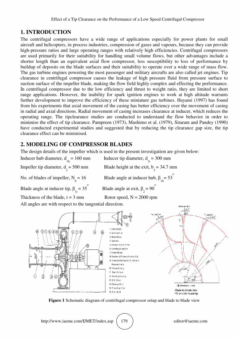
The design details of the impeller which is used in the present investigation are given below:
Inducer hub diameter, d1h
= 160 mm
Impeller tip diameter, d2
= 500 mm Blade height at the exit, b
No. of blades of impeller, Nb
= 16
Blade angle at inducer tip, β1t
= 35
Thickness of the blade, t = 3 mm
All angles are with respect to the tangential direction.
Figure 1 Schematic diagram of centrifugal compressor setup
Effect of a Tip Clearance on the Performance of a Low Speed Centrifugal Compressor
IJMET/index.asp 179
The centrifugal compressors have a wide range of applications especially for power plants for small
aircraft and helicopters, in process industries, compression of gases and vapours, because they can provide
pressure ratios and large operating ranges with relatively high efficiencies. Centrifugal compressors
are used primarily for their suitability for handling small volume flows, but other advantages include a
shorter length than an equivalent axial flow compressor, less susceptibility to loss of perf
buildup of deposits on the blade surfaces and their suitability to operate over a wide range of mass flow.
The gas turbine engines powering the most passenger and military aircrafts are also called jet engines.
essor causes the leakage of high pressure fluid from pressure surface to
suction surface of the impeller blade, making the flow field highly complex and effecting the performance.
In centrifugal compressor due to the low efficiency and thrust to weight ratio, they are limited to short
However, the inability for spark ignition engines to work at high altitude warrants
further development to improve the efficiency of these miniature gas turbines.
s that axial movement of the casing has better efficiency over the movement of casing
in radial and axial directions. Radial movement of casing increases clearance at inducer, which reduces the
operating range. The tipclearance studies are conducted to understand the flow behavior in order to
minimise the effect of tip clearance. Pampreen (1973), Mashimo et al. (1979), Sitaram and Pandey (1990)
have conducted experimental studies and suggested that by reducing the tip clearance gap size, the tip
ffect can be minimised.
MODELING OF COMPRESSOR BLADES
The design details of the impeller which is used in the present investigation are given below:
= 160 mm Inducer tip diameter, d1t
= 300 mm
= 500 mm Blade height at the exit, b2
= 34.7 mm
= 16 Blade angle at inducer hub, β1h
= 53o
= 35o
Blade angle at exit, β2
= 90o
Rotor speed, N = 2000 rpm
All angles are with respect to the tangential direction.
Schematic diagram of centrifugal compressor setup and blade to blade view
Effect of a Tip Clearance on the Performance of a Low Speed Centrifugal Compressor
The centrifugal compressors have a wide range of applications especially for power plants for small
aircraft and helicopters, in process industries, compression of gases and vapours, because they can provide
with relatively high efficiencies. Centrifugal compressors
are used primarily for their suitability for handling small volume flows, but other advantages include a
shorter length than an equivalent axial flow compressor, less susceptibility to loss of performance by
buildup of deposits on the blade surfaces and their suitability to operate over a wide range of mass flow.
The gas turbine engines powering the most passenger and military aircrafts are also called jet engines. Tip
essor causes the leakage of high pressure fluid from pressure surface to
suction surface of the impeller blade, making the flow field highly complex and effecting the performance.
io, they are limited to short
However, the inability for spark ignition engines to work at high altitude warrants
further development to improve the efficiency of these miniature gas turbines. Hayami (1997) has found
s that axial movement of the casing has better efficiency over the movement of casing
in radial and axial directions. Radial movement of casing increases clearance at inducer, which reduces the
erstand the flow behavior in order to
minimise the effect of tip clearance. Pampreen (1973), Mashimo et al. (1979), Sitaram and Pandey (1990)
have conducted experimental studies and suggested that by reducing the tip clearance gap size, the tip
The design details of the impeller which is used in the present investigation are given below:
= 34.7 mm
o
and blade to blade view
S.M. Swamy, V. Panndurangadu and J.M. Shamkumar
http://www.iaeme.com/IJMET/index.
Schematic diagram of centrifugal compressor setup
computational simulation of Centrifugal impeller with above specifications with 3mm thickness
throughout the blade for generation of three dimensional blades was done as sho
passage of the impeller with inlet at 50mm ahead of the impeller and outlet at a distance of 35mm
downstream of impeller is shown in
height. Three tip clearances of 2.2%, 5.1% and 7.9% of trailing edge blade height are obtained by moving
the casing axially. ANSYS CFX 15.0 version software is used for obtaining the solution and standard k
turbulence model is used for the closure. The computational domain is kept at
of the impeller in order to ensure that the inlet boundary conditions are not affected by the back pressure of
impeller blade. The blade gen layout with construction features related to wrapper angle, number of blades,
angles distribution and blade thickness for generation of three dimensional blades was done in order to
carry out structural analysis of the blade surfaces the software provided export options to generate
computational mesh accounting blade thickness is also explo
blade profiles generated in the software
block structured computational mesh software module called turbo grid. After these operations three
dimensional computational mesh generation process for compressor blade with boundary patches, periodic
surfaces are created.
Figure
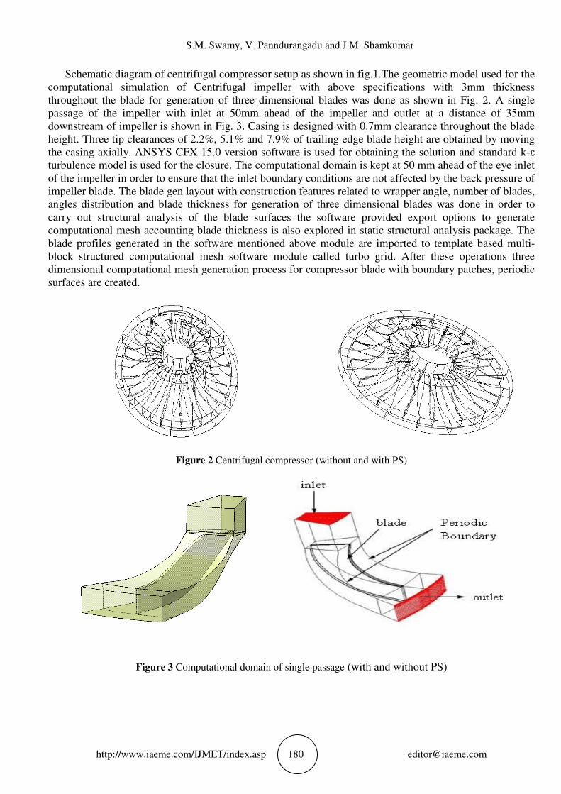
Figure 3 Computational domain of single
S.M. Swamy, V. Panndurangadu and J.M. Shamkumar
IJMET/index.asp 180
of centrifugal compressor setup as shown in fig.1.The geometric model used for the
computational simulation of Centrifugal impeller with above specifications with 3mm thickness
throughout the blade for generation of three dimensional blades was done as sho
passage of the impeller with inlet at 50mm ahead of the impeller and outlet at a distance of 35mm
downstream of impeller is shown in Fig. 3. Casing is designed with 0.7mm clearance throughout the blade
2.2%, 5.1% and 7.9% of trailing edge blade height are obtained by moving
the casing axially. ANSYS CFX 15.0 version software is used for obtaining the solution and standard k
turbulence model is used for the closure. The computational domain is kept at 50 mm ahead of the eye inlet
of the impeller in order to ensure that the inlet boundary conditions are not affected by the back pressure of
The blade gen layout with construction features related to wrapper angle, number of blades,
istribution and blade thickness for generation of three dimensional blades was done in order to
carry out structural analysis of the blade surfaces the software provided export options to generate
computational mesh accounting blade thickness is also explored in static structural analysis package. The
software mentioned above module are imported to template based multi
block structured computational mesh software module called turbo grid. After these operations three
dimensional computational mesh generation process for compressor blade with boundary patches, periodic
ure 2 Centrifugal compressor (without and with PS)
Computational domain of single passage (with and with
S.M. Swamy, V. Panndurangadu and J.M. Shamkumar
The geometric model used for the
computational simulation of Centrifugal impeller with above specifications with 3mm thickness
throughout the blade for generation of three dimensional blades was done as shown in Fig. 2. A single
passage of the impeller with inlet at 50mm ahead of the impeller and outlet at a distance of 35mm
Casing is designed with 0.7mm clearance throughout the blade
2.2%, 5.1% and 7.9% of trailing edge blade height are obtained by moving
the casing axially. ANSYS CFX 15.0 version software is used for obtaining the solution and standard k-ε
50 mm ahead of the eye inlet
of the impeller in order to ensure that the inlet boundary conditions are not affected by the back pressure of
The blade gen layout with construction features related to wrapper angle, number of blades,
istribution and blade thickness for generation of three dimensional blades was done in order to
carry out structural analysis of the blade surfaces the software provided export options to generate
structural analysis package. The
module are imported to template based multi-
block structured computational mesh software module called turbo grid. After these operations three
dimensional computational mesh generation process for compressor blade with boundary patches, periodic
Centrifugal compressor (without and with PS)
with and without PS)
Effect of a Tip Clearance on the Performance of a Low Speed Centrifugal Compressor
http://www.iaeme.com/IJMET/index.
3. COMPUTATIONAL METHOD
Most fluid flow simulation technology uses
compared to CFD simulation. And this is
the user is connecting up the dialogs within the
automatically, simply by dragging a connection between
of another. The geometry from either of the CAD
simulation model before setup option is activated. The next step is to generate the meshing solid
which several methods are provided in ANSYS
highly automated along with having a moderate to high degree of
meshing application meshing options panel displays, which allows you to
meshing preferences based on the phys
for this problem statement, with respective to this stationary, rotating components are defined. The density
going to vary compressible fluid with pressure fluid properties kept as air ideal gas. Reference pressure i
atm. Heat transfer is calculated by total energy because increase in density causes to increase in
temperature and because of rotational energy it will try to change the heat transfer rate, in total energy
methods only all this effects will get conside
because of near wall treatment is required and presence of ad
boundaries are pressure inlet with 0 Pa gauge pressure and mass flow 0.087 Kg/s at outlet respect
Rotating domain interface used as Stage. The stage averaging at the frame change interface incurs a one
time mixing loss. This loss is equivalent to assuming that the physical mixing supplied by the relative
motion between components is sufficiently
entering the downstream machine component. Stage analysis is most appropriate when the circumferential
variation of the flow is of the order of the component pitch stage for interfaces used
simulations. Physical Time scaling value was observed to be taken as 10
solution was decreased to 10-5
for better accuracy.
.
Effect of a Tip Clearance on the Performance of a Low Speed Centrifugal Compressor
IJMET/index.asp 181
COMPUTATIONAL METHODOLOGY
Most fluid flow simulation technology uses completely different meshing, loading and solving
simulation. And this is where the true power of Workbench 1
the user is connecting up the dialogs within the schematic layouts, many of these are handled
automatically, simply by dragging a connection between the outputs of one analysis system and the inputs
another. The geometry from either of the CAD Systems and Blade Gen Model can be connected to
simulation model before setup option is activated. The next step is to generate the meshing solid
which several methods are provided in ANSYS Workbench 15.0 these tools have the benefit of being
automated along with having a moderate to high degree of user control. Upon startup of the
meshing options panel displays, which allows you to quickly and easily set your
the physics you are preparing to solve. In CFX we have to use turbo mode
for this problem statement, with respective to this stationary, rotating components are defined. The density
going to vary compressible fluid with pressure fluid properties kept as air ideal gas. Reference pressure i
atm. Heat transfer is calculated by total energy because increase in density causes to increase in
temperature and because of rotational energy it will try to change the heat transfer rate, in total energy
methods only all this effects will get considered. Shear Stress Transport Turbulence model was used
because of near wall treatment is required and presence of ad-versed pressure gradient. Inlet and outlet
boundaries are pressure inlet with 0 Pa gauge pressure and mass flow 0.087 Kg/s at outlet respect
Rotating domain interface used as Stage. The stage averaging at the frame change interface incurs a one
time mixing loss. This loss is equivalent to assuming that the physical mixing supplied by the relative
motion between components is sufficiently large to cause any upstream velocity profile to mix out prior to
entering the downstream machine component. Stage analysis is most appropriate when the circumferential
variation of the flow is of the order of the component pitch stage for interfaces used
simulations. Physical Time scaling value was observed to be taken as 10-3
s. Accuracy criteria of RMS
for better accuracy.
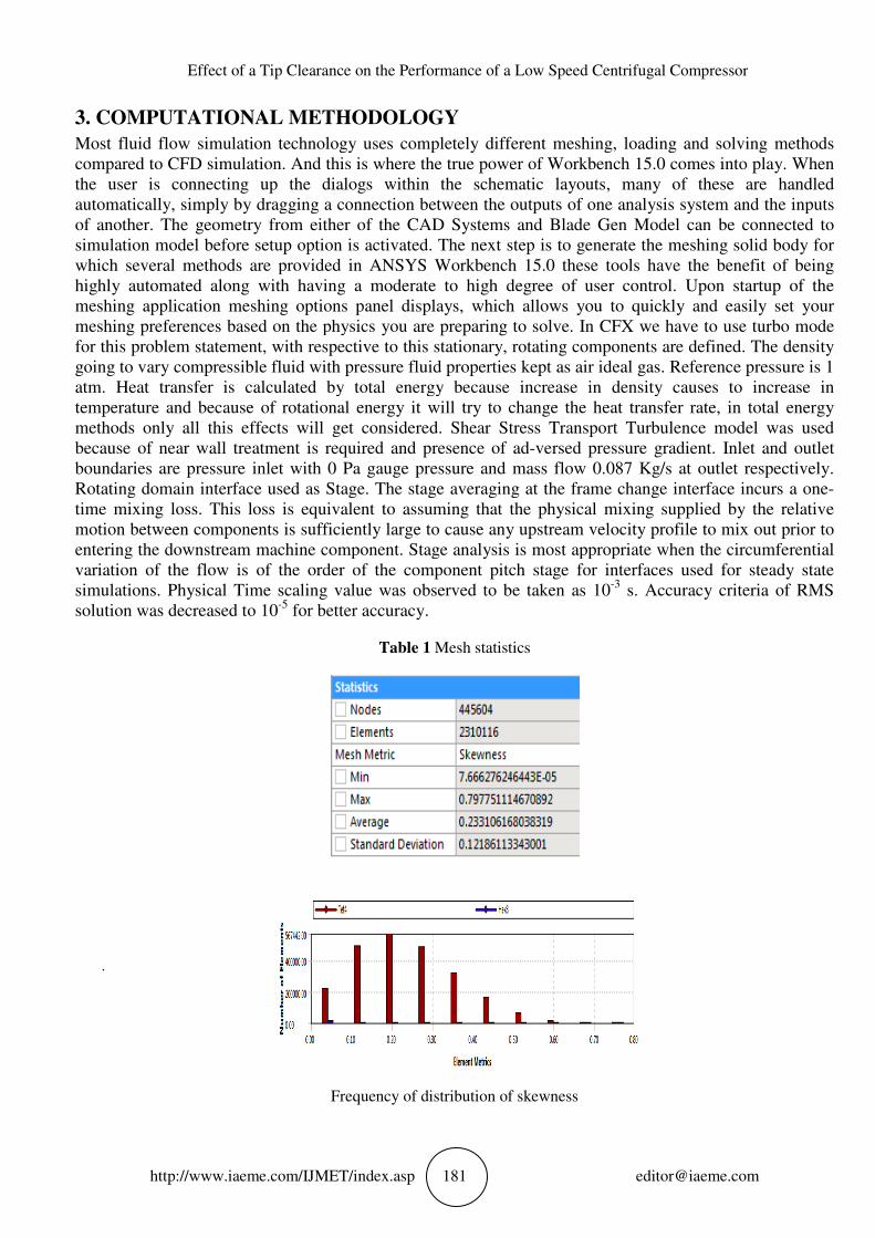
Table 1 Mesh statistics
Frequency of distribution of skewness
Effect of a Tip Clearance on the Performance of a Low Speed Centrifugal Compressor
completely different meshing, loading and solving methods
where the true power of Workbench 15.0 comes into play. When
schematic layouts, many of these are handled
the outputs of one analysis system and the inputs
Systems and Blade Gen Model can be connected to
simulation model before setup option is activated. The next step is to generate the meshing solid body for
these tools have the benefit of being
user control. Upon startup of the
quickly and easily set your
In CFX we have to use turbo mode
for this problem statement, with respective to this stationary, rotating components are defined. The density
going to vary compressible fluid with pressure fluid properties kept as air ideal gas. Reference pressure is 1
atm. Heat transfer is calculated by total energy because increase in density causes to increase in
temperature and because of rotational energy it will try to change the heat transfer rate, in total energy
red. Shear Stress Transport Turbulence model was used
versed pressure gradient. Inlet and outlet
boundaries are pressure inlet with 0 Pa gauge pressure and mass flow 0.087 Kg/s at outlet respectively.
Rotating domain interface used as Stage. The stage averaging at the frame change interface incurs a one-
time mixing loss. This loss is equivalent to assuming that the physical mixing supplied by the relative
large to cause any upstream velocity profile to mix out prior to
entering the downstream machine component. Stage analysis is most appropriate when the circumferential
variation of the flow is of the order of the component pitch stage for interfaces used for steady state
s. Accuracy criteria of RMS
S.M. Swamy, V. Panndurangadu and J.M. Shamkumar
http://www.iaeme.com/IJMET/index.asp 182 [email protected]
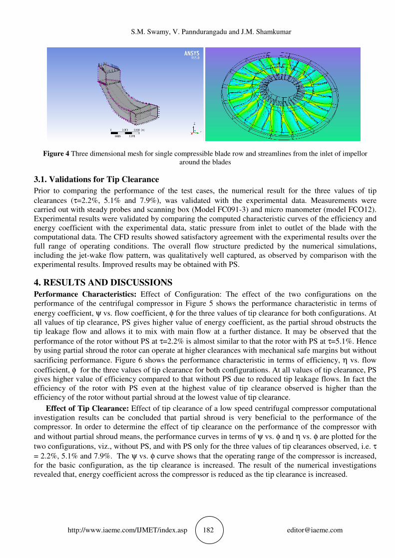
Figure 4 Three dimensional mesh for single compressible blade row and streamlines from the inlet of impellor
around the blades
3.1. Validations for Tip Clearance
Prior to comparing the performance of the test cases, the numerical result for the three values of tip
clearances (τ=2.2%, 5.1% and 7.9%), was validated with the experimental data. Measurements were
carried out with steady probes and scanning box (Model FC091-3) and micro manometer (model FCO12).
Experimental results were validated by comparing the computed characteristic curves of the efficiency and
energy coefficient with the experimental data, static pressure from inlet to outlet of the blade with the
computational data. The CFD results showed satisfactory agreement with the experimental results over the
full range of operating conditions. The overall flow structure predicted by the numerical simulations,
including the jet-wake flow pattern, was qualitatively well captured, as observed by comparison with the
experimental results. Improved results may be obtained with PS.
4. RESULTS AND DISCUSSIONS
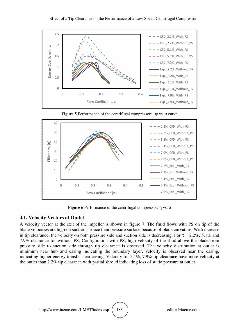
Performance Characteristics: Effect of Configuration: The effect of the two configurations on the
performance of the centrifugal compressor in Figure 5 shows the performance characteristic in terms of
energy coefficient, ψ vs. flow coefficient, φ for the three values of tip clearance for both configurations. At
all values of tip clearance, PS gives higher value of energy coefficient, as the partial shroud obstructs the
tip leakage flow and allows it to mix with main flow at a further distance. It may be observed that the
performance of the rotor without PS at τ=2.2% is almost similar to that the rotor with PS at τ=5.1%. Hence
by using partial shroud the rotor can operate at higher clearances with mechanical safe margins but without
sacrificing performance. Figure 6 shows the performance characteristic in terms of efficiency, η vs. flow
coefficient, φ for the three values of tip clearance for both configurations. At all values of tip clearance, PS
gives higher value of efficiency compared to that without PS due to reduced tip leakage flows. In fact the
efficiency of the rotor with PS even at the highest value of tip clearance observed is higher than the
efficiency of the rotor without partial shroud at the lowest value of tip clearance.
Effect of Tip Clearance: Effect of tip clearance of a low speed centrifugal compressor computational
investigation results can be concluded that partial shroud is very beneficial to the performance of the
compressor. In order to determine the effect of tip clearance on the performance of the compressor with
and without partial shroud means, the performance curves in terms of ψ vs. φ and η vs. φ are plotted for the
two configurations, viz., without PS, and with PS only for the three values of tip clearances observed, i.e. τ
= 2.2%, 5.1% and 7.9%. The ψ vs. φ curve shows that the operating range of the compressor is increased,
for the basic configuration, as the tip clearance is increased. The result of the numerical investigations
revealed that, energy coefficient across the compressor is reduced as the tip clearance is increased.
Effect of a Tip Clearance on the Performance of a Low Speed Centrifugal Compressor
http://www.iaeme.com/IJMET/index.asp 183 [email protected]
Figure 5 Performance of the centrifugal compressor: ψ vs. φ curve
Figure 6 Performance of the centrifugal compressor: η vs. φ
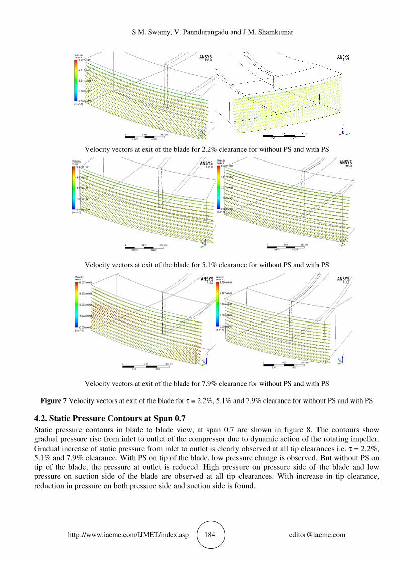
4.1. Velocity Vectors at Outlet
A velocity vector at the exit of the impeller is shown in figure 7. The fluid flows with PS on tip of the
blade velocities are high on suction surface than pressure surface because of blade curvature. With increase
in tip clearance, the velocity on both pressure side and suction side is decreasing. For τ = 2.2%, 5.1% and
7.9% clearance for without PS. Configuration with PS, high velocity of the fluid above the blade from
pressure side to suction side through tip clearance is observed. The velocity distribution at outlet is
minimum near hub and casing indicating the boundary layer, velocity is observed near the casing,
indicating higher energy transfer near casing. Velocity for 5.1%, 7.9% tip clearance have more velocity at
the outlet than 2.2% tip clearance with partial shroud indicating loss of static pressure at outlet.
0
0.5
1
1.5
2
2.5
0 0.1 0.2 0.3 0.4
En
erg
y C
oe
ffic
ien
t, ψ
Flow Coefficient, φ
CFD_2.2%_With_PS
CFD_2.2%_Without_PS
CFD_5.1%_With_PS
CFD_5.1%_Without_PS
CFD_7.9%_With_PS
Exp._2.2%_Without_PS
Exp._2.2%_With_PS
Exp._5.1%_With_PS
Exp._5.1%_Without_PS
Exp._7.9%_With_PS
Exp._7.9%_Without_PS
0
10
20
30
40
50
60
0 0.1 0.2 0.3 0.4 0.5
Eff
icie
ncy
, (η
)
Flow Coefficient (φ)
2.2%_CFD_With_PS
2.2%_CFD_Without_PS
5.1%_CFD_With_PS
5.1%_CFD_Without_PS
7.9%_CFD_With_PS
7.9%_CFD_Without_PS
2.2%_Exp._With_PS
2.2%_Exp_Without_PS
5.1%_Exp._With_PS
5.1%_Exp._Without_PS
7.9%_Exp._With_PS
S.M. Swamy, V. Panndurangadu and J.M. Shamkumar
http://www.iaeme.com/IJMET/index.
Velocity vectors at exit of the blade
Velocity vectors at exit of the blade
Velocity vectors at exit of the blade
Figure 7 Velocity vectors at exit of the blade
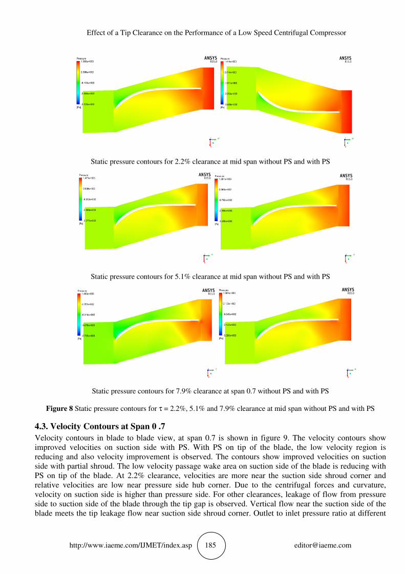
4.2. Static Pressure Contours at Span 0.7
Static pressure contours in blade to blade view, at span 0.7
gradual pressure rise from inlet to outlet of the compressor due to dynamic action of the rotating impeller.
Gradual increase of static pressure from inlet to outlet is clearly observed at all tip clearances
5.1% and 7.9% clearance. With PS
tip of the blade, the pressure at outlet is reduced. High pressure on pressure side of the blade and low
pressure on suction side of the blade are observed at all tip clearances. With
reduction in pressure on both pressure side and suction side is found.
S.M. Swamy, V. Panndurangadu and J.M. Shamkumar
IJMET/index.asp 184
Velocity vectors at exit of the blade for 2.2% clearance for without PS and with PS
Velocity vectors at exit of the blade for 5.1% clearance for without PS and with PS
Velocity vectors at exit of the blade for 7.9% clearance for without PS and with
Velocity vectors at exit of the blade for τ = 2.2%, 5.1% and 7.9% clearance for without PS and with PS
Static Pressure Contours at Span 0.7
ressure contours in blade to blade view, at span 0.7 are shown in figure
gradual pressure rise from inlet to outlet of the compressor due to dynamic action of the rotating impeller.
Gradual increase of static pressure from inlet to outlet is clearly observed at all tip clearances
. With PS on tip of the blade, low pressure change is observed. But without PS on
tip of the blade, the pressure at outlet is reduced. High pressure on pressure side of the blade and low
pressure on suction side of the blade are observed at all tip clearances. With
reduction in pressure on both pressure side and suction side is found.
S.M. Swamy, V. Panndurangadu and J.M. Shamkumar
for 2.2% clearance for without PS and with PS
% clearance for without PS and with PS
for 7.9% clearance for without PS and with PS
clearance for without PS and with PS
figure 8. The contours show
gradual pressure rise from inlet to outlet of the compressor due to dynamic action of the rotating impeller.
Gradual increase of static pressure from inlet to outlet is clearly observed at all tip clearances i.e. τ = 2.2%,
on tip of the blade, low pressure change is observed. But without PS on
tip of the blade, the pressure at outlet is reduced. High pressure on pressure side of the blade and low
pressure on suction side of the blade are observed at all tip clearances. With increase in tip clearance,
Effect of a Tip Clearance on the Performance of a Low Speed Centrifugal Compressor
http://www.iaeme.com/IJMET/index.
Static pressure contours for 2.2% clearance at mid span without PS and with PS
Static pressure contours for 5.1% clearance at mid span without PS and
Static pressure contours for 7.9% clearance at span
Figure 8 Static pressure contours for
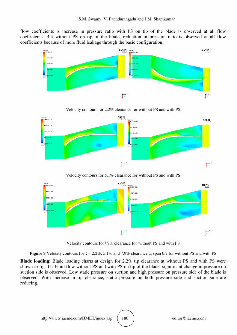
4.3. Velocity Contours at Span 0 .7
Velocity contours in blade to blade view, at span 0.7 is shown in
improved velocities on suction side with PS.
reducing and also velocity improvement is observed.
side with partial shroud. The low velocity passage wake area on suction side of the blade is reducing with
PS on tip of the blade. At 2.2% clearance, velocities are more near the suction side shroud corner a
relative velocities are low near pressure side hub corner. Due to the centrifugal forces and curvature,
velocity on suction side is higher than pressure side. For other clearances, leakage of flow from pressure
side to suction side of the blade through
blade meets the tip leakage flow near suction side shroud corner.
Effect of a Tip Clearance on the Performance of a Low Speed Centrifugal Compressor
IJMET/index.asp 185
pressure contours for 2.2% clearance at mid span without PS and with PS
pressure contours for 5.1% clearance at mid span without PS and
pressure contours for 7.9% clearance at span 0.7 without PS and with PS
pressure contours for τ = 2.2%, 5.1% and 7.9% clearance at mid span without PS and with PS
Velocity Contours at Span 0 .7
Velocity contours in blade to blade view, at span 0.7 is shown in figure 9. The velocity contours show
improved velocities on suction side with PS. With PS on tip of the blade, the low velocity region is
reducing and also velocity improvement is observed. The contours show improved velocities on suction
side with partial shroud. The low velocity passage wake area on suction side of the blade is reducing with
At 2.2% clearance, velocities are more near the suction side shroud corner a
relative velocities are low near pressure side hub corner. Due to the centrifugal forces and curvature,
velocity on suction side is higher than pressure side. For other clearances, leakage of flow from pressure
side to suction side of the blade through the tip gap is observed. Vertical flow near the suction side of the
blade meets the tip leakage flow near suction side shroud corner. Outlet to inlet pressure ratio at different
Effect of a Tip Clearance on the Performance of a Low Speed Centrifugal Compressor
pressure contours for 2.2% clearance at mid span without PS and with PS
pressure contours for 5.1% clearance at mid span without PS and with PS
without PS and with PS
= 2.2%, 5.1% and 7.9% clearance at mid span without PS and with PS
The velocity contours show
With PS on tip of the blade, the low velocity region is
The contours show improved velocities on suction
side with partial shroud. The low velocity passage wake area on suction side of the blade is reducing with
At 2.2% clearance, velocities are more near the suction side shroud corner and
relative velocities are low near pressure side hub corner. Due to the centrifugal forces and curvature,
velocity on suction side is higher than pressure side. For other clearances, leakage of flow from pressure
the tip gap is observed. Vertical flow near the suction side of the
Outlet to inlet pressure ratio at different
S.M. Swamy, V. Panndurangadu and J.M. Shamkumar
http://www.iaeme.com/IJMET/index.
flow coefficients is increase in pressure ratio with PS on tip of the blade is
coefficients. But without PS on tip of the blade, reduction in pressure ratio is observed at all flow
coefficients because of more fluid leakage through the basic configuration.
Velocity contours for 2.2% clearance for without PS a
Velocity contours for 5.1% clearance for without PS and with PS
Velocity contours for
Figure 9 Velocity contours for τ
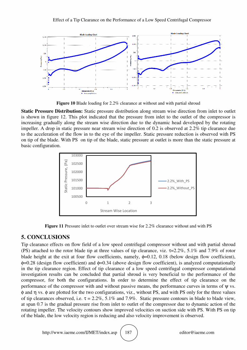
Blade loading: Blade loading ch
shown in fig. 11. Fluid flow without PS and with PS on tip of the blade, significant change in pressure on
suction side is observed. Low static pressure on
observed. With increase in tip clearance, static pressure on both pressure side and suction side are
reducing.
S.M. Swamy, V. Panndurangadu and J.M. Shamkumar
IJMET/index.asp 186
flow coefficients is increase in pressure ratio with PS on tip of the blade is
coefficients. But without PS on tip of the blade, reduction in pressure ratio is observed at all flow
coefficients because of more fluid leakage through the basic configuration.
contours for 2.2% clearance for without PS and with PS
contours for 5.1% clearance for without PS and with PS
contours for7.9% clearance for without PS and with PS
τ = 2.2%, 5.1% and 7.9% clearance at span 0.7 for without PS and with PS
Blade loading charts at design for 2.2% tip clearance at without PS and with PS
shown in fig. 11. Fluid flow without PS and with PS on tip of the blade, significant change in pressure on
suction side is observed. Low static pressure on suction and high pressure on pressure side of the blade is
observed. With increase in tip clearance, static pressure on both pressure side and suction side are
S.M. Swamy, V. Panndurangadu and J.M. Shamkumar
flow coefficients is increase in pressure ratio with PS on tip of the blade is observed at all flow
coefficients. But without PS on tip of the blade, reduction in pressure ratio is observed at all flow
nd with PS
contours for 5.1% clearance for without PS and with PS
% clearance for without PS and with PS
for without PS and with PS
for 2.2% tip clearance at without PS and with PS were
shown in fig. 11. Fluid flow without PS and with PS on tip of the blade, significant change in pressure on
suction and high pressure on pressure side of the blade is
observed. With increase in tip clearance, static pressure on both pressure side and suction side are
Effect of a Tip Clearance on the Performance of a Low Speed Centrifugal Compressor
http://www.iaeme.com/IJMET/index.
Figure 10 Blade loading for 2.2% clearance at without and with partial shroud
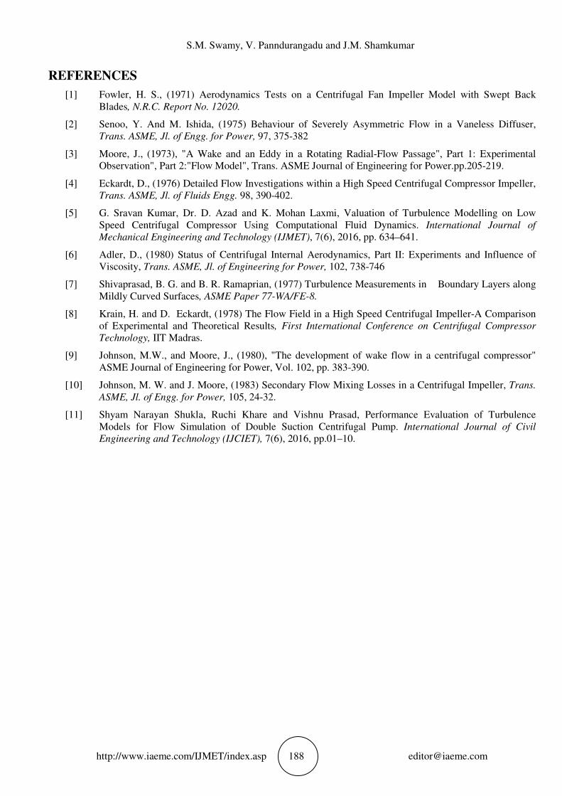
Static Pressure Distribution: Static pressure distribution along stream
is shown in figure 12. This plot indicated
increasing gradually along the stream wise direction due to the dynamic head
impeller. A drop in static pressure near stream
to the acceleration of the flow in to the eye of the impeller. Static pressure reduction is observed with PS
on tip of the blade. With PS on tip of the blade, static pressure at outlet is more than the static pressure
basic configuration.
Figure 11 Pressure inlet to outlet over stream
5. CONCLUSIONS
Tip clearance effects on flow field of a low speed centrifugal compressor
(PS) attached to the rotor blade tip at three values of tip clearance, viz.
blade height at the exit at four flow coefficients, namely,
φ=0.28 (design flow coefficient) and
in the tip clearance region. Effect of tip clearance of a low speed centrifugal compressor computational
investigation results can be concluded that par
compressor, for both the configurations. In order to determine the effect of tip clearance on the
performance of the compressor with and without passive means, the performance curves in terms of
φ and η vs. φ are plotted for the two configurations, viz., without PS, and with PS only for the three values
of tip clearances observed, i.e. τ = 2.2%, 5.1% and 7.9%.
at span 0.7 is the gradual pressure rise from inlet to outlet of the compressor due to dynamic action of the
rotating impeller. The velocity contours show improved velocities on suction side with PS. With PS
of the blade, the low velocity region is reducing and also velocity improvement is observed
100500
101000
101500
102000
102500
103000
0
Sta
tic
Pre
ssu
re,
(Pa
)
Effect of a Tip Clearance on the Performance of a Low Speed Centrifugal Compressor
IJMET/index.asp 187
Blade loading for 2.2% clearance at without and with partial shroud
Static pressure distribution along stream wise direction from inlet to outlet
indicated that the pressure from inlet to the outlet of the compressor is
increasing gradually along the stream wise direction due to the dynamic head
impeller. A drop in static pressure near stream wise direction of 0.2 is observed
to the acceleration of the flow in to the eye of the impeller. Static pressure reduction is observed with PS
on tip of the blade. With PS on tip of the blade, static pressure at outlet is more than the static pressure
Pressure inlet to outlet over stream wise for 2.2% clearance without
Tip clearance effects on flow field of a low speed centrifugal compressor without and with partial
(PS) attached to the rotor blade tip at three values of tip clearance, viz. τ=2.2%, 5.1% and 7.9% of rotor
flow coefficients, namely, φ=0.12, 0.18 (below design flow coefficient),
=0.28 (design flow coefficient) and φ=0.34 (above design flow coefficient),
Effect of tip clearance of a low speed centrifugal compressor computational
investigation results can be concluded that partial shroud is very beneficial to the performance of the
compressor, for both the configurations. In order to determine the effect of tip clearance on the
performance of the compressor with and without passive means, the performance curves in terms of
are plotted for the two configurations, viz., without PS, and with PS only for the three values
= 2.2%, 5.1% and 7.9%. Static pressure contours in blade to blade view,
at span 0.7 is the gradual pressure rise from inlet to outlet of the compressor due to dynamic action of the
The velocity contours show improved velocities on suction side with PS. With PS
of the blade, the low velocity region is reducing and also velocity improvement is observed
1 2 3
Stream Wise Location
2.2%_With_PS
2.2%_Without_PS
Effect of a Tip Clearance on the Performance of a Low Speed Centrifugal Compressor
Blade loading for 2.2% clearance at without and with partial shroud
wise direction from inlet to outlet
that the pressure from inlet to the outlet of the compressor is
increasing gradually along the stream wise direction due to the dynamic head developed by the rotating
wise direction of 0.2 is observed at 2.2% tip clearance due
to the acceleration of the flow in to the eye of the impeller. Static pressure reduction is observed with PS
on tip of the blade. With PS on tip of the blade, static pressure at outlet is more than the static pressure at
without and with PS
without and with partial shroud
=2.2%, 5.1% and 7.9% of rotor
(below design flow coefficient),
=0.34 (above design flow coefficient), is analyzed computationally
Effect of tip clearance of a low speed centrifugal compressor computational
tial shroud is very beneficial to the performance of the
compressor, for both the configurations. In order to determine the effect of tip clearance on the
performance of the compressor with and without passive means, the performance curves in terms of ψ vs.
are plotted for the two configurations, viz., without PS, and with PS only for the three values
Static pressure contours in blade to blade view,
at span 0.7 is the gradual pressure rise from inlet to outlet of the compressor due to dynamic action of the
The velocity contours show improved velocities on suction side with PS. With PS on tip
of the blade, the low velocity region is reducing and also velocity improvement is observed.
2.2%_With_PS
2.2%_Without_PS
S.M. Swamy, V. Panndurangadu and J.M. Shamkumar
http://www.iaeme.com/IJMET/index.asp 188 [email protected]
REFERENCES
[1] Fowler, H. S., (1971) Aerodynamics Tests on a Centrifugal Fan Impeller Model with Swept Back
Blades, N.R.C. Report No. 12020.
[2] Senoo, Y. And M. Ishida, (1975) Behaviour of Severely Asymmetric Flow in a Vaneless Diffuser,
Trans. ASME, Jl. of Engg. for Power, 97, 375-382
[3] Moore, J., (1973), "A Wake and an Eddy in a Rotating Radial-Flow Passage", Part 1: Experimental
Observation", Part 2:"Flow Model", Trans. ASME Journal of Engineering for Power.pp.205-219.
[4] Eckardt, D., (1976) Detailed Flow Investigations within a High Speed Centrifugal Compressor Impeller,
Trans. ASME, Jl. of Fluids Engg. 98, 390-402.
[5] G. Sravan Kumar, Dr. D. Azad and K. Mohan Laxmi, Valuation of Turbulence Modelling on Low
Speed Centrifugal Compressor Using Computational Fluid Dynamics. International Journal of
Mechanical Engineering and Technology (IJMET), 7(6), 2016, pp. 634–641.
[6] Adler, D., (1980) Status of Centrifugal Internal Aerodynamics, Part II: Experiments and Influence of
Viscosity, Trans. ASME, Jl. of Engineering for Power, 102, 738-746
[7] Shivaprasad, B. G. and B. R. Ramaprian, (1977) Turbulence Measurements in Boundary Layers along
Mildly Curved Surfaces, ASME Paper 77-WA/FE-8.
[8] Krain, H. and D. Eckardt, (1978) The Flow Field in a High Speed Centrifugal Impeller-A Comparison
of Experimental and Theoretical Results, First International Conference on Centrifugal Compressor
Technology, IIT Madras.
[9] Johnson, M.W., and Moore, J., (1980), "The development of wake flow in a centrifugal compressor"
ASME Journal of Engineering for Power, Vol. 102, pp. 383-390.
[10] Johnson, M. W. and J. Moore, (1983) Secondary Flow Mixing Losses in a Centrifugal Impeller, Trans.
ASME, Jl. of Engg. for Power, 105, 24-32.
[11] Shyam Narayan Shukla, Ruchi Khare and Vishnu Prasad, Performance Evaluation of Turbulence
Models for Flow Simulation of Double Suction Centrifugal Pump. International Journal of Civil
Engineering and Technology (IJCIET), 7(6), 2016, pp.01–10.