Embed Size (px)
Citation preview

Proceedings of the 1st Global Power and Propulsion Forum GPPF 2017
Jan 16-18, 2017, Zurich, Switzerland www.pps.global
This work is licensed under a Creative Commons Attribution-NonCommercial-NoDerivatives 4.0 International License
GPPF-2017-65
FEATURE OF INTERNAL FLOW PHENOMENA OF SELF RECIRCULATION CASING TREATMENT IN A CENTRIFUGAL COMPRESSOR FOR
TURBOCHARGERS
Tadashi Kanzaka Research & Innovation Center,
Mitsubishi Heavy Industries, Ltd. [email protected]
Sagamihara, Japan
Seiichi Ibaraki Research & Innovation Center,
Mitsubishi Heavy Industries, Ltd. [email protected]
Sagamihara, Japan
ABSTRACT Today, turbocharging has become a fundamental
technology to realize engine downsizing, which is an effective strategy for low carbon emissions. As for the compressor of turbocharger, enhancement of an operating range is strongly required. To increase the operating range, self recirculation casing treatment is used for some turbocharger applications. This recirculation device usually has bleed slots at shroud wall near impeller leading edge and several struts to form recirculation flow path. Since the flow inside recirculation flow path is very complexed, geometry of flow path affects on total performance and inducer flow of impeller.
In this study, the effects of self recirculation casing treatment on internal flow and association between the number of struts were investigated using experimental approach of stereoscopic particle image velocimetry(PIV) at the exit of recirculation flow path and numerical approach of steady Reynolds Averaged Navier-Stokes(RANS) analysis. The numerical results show good agreement with performance data and PIV results and could predict recirculation flow from casing treatment well. In the compressor without casing treatment, blade stall occurs at the shroud of impeller leading edge. In the compressor with casing treatment, on the other hand, the blade stall was suppressed due to the recirculation flow. In the compressor with 13 struts, axial velocity near shroud wall is a little higher than that of compressor with 3 struts and circumferential velocity decreases by 30%. These results show that the increase of the number of struts has effect of uniformalization of spanwise axial velocity distribution and reduce of swirling flow at leading edge of impeller.
INTRODUCTION Demands of turbocharger are growing year by year in
the background of exhaust gas and fuel consumption regulations. Especially, enhancement of an operating range of a centrifugal compressor is strongly required, however, it is difficult because of trade-off between pressure ratio and surging characteristics. In attempt to increase the operating range of centrifugal compressors, a number of approaches have been considered in the past. As a way of enhancing operating range by using extra devices, casing treatment with recirculation bypass of inducer was first investigated by Fisher [1] in the 1980s and is employed for some automotive applications. Also, some extra devices such as variable inlet guide vanes [2] and low solidity diffusers [3] have been studied. Furthermore, two stage turbocharging has been applied to give a considerable wider operating range [4]. In the automotive industry, due to the packaging and cost restriction recirculation devices is preferred to use passive bleeds system.
Recirculation device usually has circular bleed slots at shroud wall near impeller leading edge and several struts to form recirculation flow path. This enables to recirculate flow from the impeller inducer to the inlet of the compressor and has been confirmed to improve the compressor stability. Chen et al. [5] reviewed its development in more twenty years history and explored the mechanisms that deliver the performance improvement and put forward suggestions for possible further improvement. Experimental and numerical study for several design parameters of casing treatment such as cavity length, the slot location and circumferential gap were studied. Sivagnanasundaram et al. [6] presented an design policy of centrifugal compressor incorporating a classical bleeds slot system with various slot positions. Jung et al. [7] studied various design configurations of casing

2
treatment using numerical approach. This study found that the bleed position and width were the primary factors controlling performance of casing treatment. On the other hand, Tamaki et al. [8] focused on the geometry of recirculation flow path and applied non-axisymmetric recirculation devices which had improved the behavior of the compressor stage taking the asymmetry of the bleed slot and volute with a vaneless diffuser.
As for experimental approach, actual working mechanisms was investigated by using particle image velocimetry(PIV). PIV could measure whole velocity fields by taking two images shortly after each other and calculating the distance individual particles travelled within this time. From the known time difference and the measured displacement the velocity is calculated. Gancedo et al. [9] conducted stereoscopic PIV measurements for centrifugal compressor with casing treatment to obtain three dimension velocity flow field. The influence of recirculation device on inlet velocity flow field was shown with the presence of localized flow recirculation near shroud wall.
Besides, since flow structure inside recirculation path shows very complex due to strong swirl flow from impeller, it is thought that configuration of the struts affects on internal flow and performance. However, detailed measurement and numetical study for the effect of number of struts are few. In the present study, the authors performed experiments of stereoscopic PIV and steady numerical simulation of compressors without casing treatment, with 3 struts casing treatment and 13 struts casing treatment in order to evaluate the effect of the number of struts on performance and internal flow of impeller.
EFFECT OF STRUTS ON PERFORMANCE To clarify the effects of the number of struts on
performance, performance measurements were conducted as for compressor without casing treatment, compressor with casing treatments which have 3 struts and 12 struts. The compressor performance comparisons are showin in Fig.1. The flow rate is normalized by choking volume flow rate at 100% rotational speed of the compressor without casing treatment. Between 81% speed and 100% speed, the slope of the pressure characteristic curve is positive in the compressor without casing treatment. On the other hand, pressure ratio characteristic curves are improved in the compressors with casing treatment. In particular, surging flow rate is reduced in the compressor with recirculation device which has 12 struts compared with 3 struts. Therefore, this result shows that surging characteristic changes when the number of struts are a a lot.
EXPERIMENTAL SET UP To clarify actual working mechanisms of struts,
stereoscopic PIV were conducted as for the compressor without casing treatment and compressor with casing treatments which have 3 struts and 13 struts. Test compressor impeller has backswept blade and its outlet diameter 92 mm.
This type of turbocharger was selected because its size would be sufficiently large to enable flow visualization. Although impeller is not same as previous performance measurement as shown in Fig.1, the qualitative effects of the number of struts on internal flow can be evaluated by using common impeller in this pressure measurement and PIV.
Cross flow stereoscopic PIV set up is shown as Fig.2. Inlet pipe was removed in order to allow planer flow visualization clearly. LaVision with DaVis 8.3 was used to process PIV measurement. The cross flow seeded with Di-Ethyl-Hexyl-Sebacate(DEHS) though the use of in-house seeding generator with a diameter less than 1 μm. The particles were illuminated by a light sheet which thickness is about 1.8 mm. The light sheet was created by a double pulse Nd:YAG laser. The PIV laser was operated at a wavelength of 532 nm, with each pulse delivering 50 mJ of energy. The scattered laser light from tracer particles was recorded with two 2048 pixels x 2048 pixels CCD cameras. The window of view was approximately 110 mm x 110 mm, yielding a spatial resolution of 18.6 pixels/mm. The time lag between the laser pulse to illuminate DEHS particles was adjusted according to the flow velocity and camera magnification. In the present study, local maximum velocity was assumed to be 90 m/s and the time lag was set so that particle displacement between laser pulse was less than 8 pixels. As a result, the time lag Δt=4.5 μs was used. The laser plane of visualization was located 2 mm upstream of the compressor
1.0
1.5
2.0
2.5
3.0
3.5
0.0 0.2 0.4 0.6 0.8 1.0 1.2
Tota
l Pre
ssur
e R
atio
π[-
]
Volume Flow Ratio Q0/Qmax[-]
12 struts 3 struts Withoutcasing treatment
Fig.1 Comparison of Compressor Characteristics
(b) Compressor performance
3 struts 12 struts (a) Recirculation device
42% 53%
69% 81%
92%
100% N/Nmax=
12struts 3struts Without casing treatment

3
inlet edge normal to the axial direction of inlet flow. The angle between a camera and axial direction of inlet flow(θ) is about 39.8 deg. Thus, total stereoscopic angle is 79. 6 deg between two cameras. To obtain time averaged velocity field at each operation points, this measurement was repeated 200 times and the instant PIV data were averaged.
NUMERICAL SCHEME In this study, numerical simulation was conducted in
order to analyze the effects of casing treatment. ANSYS CFX version 14.5 was used for numerical calculation and Turbogrid and ICEM software were used in meshing process. In order to simulate flow improvement by recirculation flow at the casing treatment, evaluation of the recirculation flow rate is important. Since distortion of the flow is generated by the circumferential pressure distributions in the casing treatment and the scroll within the low flow rate operation in particular, numerical calculations were performed including whole impeller, and casing treatment, vaneless diffuser and scroll applying the Frozen-Rotor in boundary conditions. The calculation domains are shown in Fig.3. In this calculation, inlet pipe domain was removed and hemisphere inlet boundary was used as shown in Fig.3 so as to simulate the condition of PIV measurement. As the turbulence model, the SST k-omega turbulence model was adopted. And the numbers of cells were about 6,001,000 for inlet domain, 3,512,000 for impeller, 2,198,000 for diffuser, 2,117,000 for scroll. As for the impeller domain, hexahedral mesh is used
by using Turbogrid. As for the other part, tetrahedral and prism mesh are used by using ICEM CFD. For the CFD setup, the inlet boundary condition have been defined as the total pressure and temperature. Two types of boundary conditions have been used: the average static pressure at choke point and mass flow rate from mid-map to the surge point
Fig.2 PIV measurement set-up
8.6°
79.6°
Nd:YAG Laser
1100mm
660mm
PIV Cemara
1.8mm
Test Compressor
Fig.3 Calculation domain
(a) Calculation domain
(b) Computational grid
Inlet boundary Scroll domain
Casing treatment
Impeller
Scroll
Impeller
Casing treatment

4
RESULTS AND DISCUSSION Fig.4 shows the comparison of performance
characteristics obtained in the experiment and numerical calculation. The RANS calculations were conducted at five points where Q0/Qmax=0.36, 0.50, 0.76 0.95 and 1.00. Note that surge flow rate is not plotted in the figure. The pressure ratio was normalized by pressure ratio at design point and efficiency was normalized by the maximum efficiency of the compressor without casing treatment. The calculation results predict a little higher head coefficient and efficiency, but these are well agreed with the experimental results. At higher flow rate condition where Q0/Qmax is higher than 0.76, the performance differences between three cases are little. On the other hand, at low flow rate where Q0/Qmax is less than 0.50, the pressure head of the compressor with casing treatment is higher than that of compressor without casing treatment. Also, the efficiency of the compressor obtained from numerical simulation with casing treatment is lower than the compressor with casing treatment, which is same trend as measurement results. It is considered that recirculation flow from leading edge occurs and increase blade loading. To see the performance result with casing
treatment, pressure head in the compressor with 13 struts is higher than the compressor with 3 struts.
Fig.5 and Fig.6 show comparisons of PIV result and calculation result of time averaged axial velocity distribution, planar velocity vector and circumferential velocity distribution on laser light sheet at lower flow rate condition where Q0/Qmax = 0.36. In these figures, the axial velocity and circumferential velocity are normalized by impeller leading edge tip speed. The Laser sheet was located about 2 mm upstream of the compressor inlet edge. Rotational direction of impeller is in a clockwise direction. Note that due to the choice of cooordinate system, the flow entering from inlet represents positive value of Cm, while recirculation flow or reversed flow represents negative value. And flow in the same direction of rotation of impeller represents positive value of Ct. In the Fig.5 and Fig.6, calculation result predicts high circumferential velocity at near shroud wall compared to measurement result in the compressor without casing treatment. In the calculation result without casing treatment, small reversed flow near shroud wall was seen and strong swirling flow was detected near shroud wall. The swirling flow is thought to be due to locally reversed flow of
Fig.4 Performance characteristics
(a) Normalized pressure ratio
(b) Normalized efficiency
0.60
0.70
0.80
0.90
1.00
1.10
0.0 0.2 0.4 0.6 0.8 1.0 1.2
Nor
mal
ized
Effi
cien
cy[-
]
Volume Flow Ratio, Q0/Qmax[-]
EXP(without CT)EXP(3 struts)EXP(13 struts)
0.60
0.70
0.80
0.90
1.00
1.10
0.0 0.2 0.4 0.6 0.8 1.0 1.2
Nor
mal
ized
Effi
cien
cy[-
]
Volume Flow Ratio, Q0/Qmax[-]
CFD(without CT)CFD(3 struts)CFD(13 struts)
Volume Flow Ratio, Q0/Qmax[-]
Volume Flow Ratio, Q0/Qmax[-]
0.6
0.7
0.8
0.9
1.0
1.1
1.2
0.0 0.2 0.4 0.6 0.8 1.0 1.2
EXP(without CT)EXP(3 struts)EXP(13 struts)
Nor
mal
ized
Pres
sure
ratio
, π/π
desi
gn[-
]
0.6
0.7
0.8
0.9
1.0
1.1
1.2
0.0 0.2 0.4 0.6 0.8 1.0 1.2
CFD(without CT)CFD(3 struts)CFD(13 struts)
Nor
mal
ized
Pres
sure
ratio
, π/π
desi
gn[-
]

5
Fig.5 Normalized axial velocity distribution at exit of recirculation flow: Q0/Qmax=0.36 (b) CFD results
(ii) 3 struts
(a) PIV results (i) Without casing treatment (ii) 3 struts
(iii) 13 struts
(iii) 13 struts
(i) Without casing treatment
Fig.6 Normalized circumferential Velocity distribution at exit of recirculation flow: Q0/Qmax=0.36 (b) CFD results
(i) Without casing treatment (ii) 3 struts
(a) PIV results (i) Without casing treatment (ii) 3 struts
(iii) 13 struts
(iii) 13 struts

6
impeller. Thus, it is considered that calculation result overestimated reversed flow. As for compressor with casing treatment, on the other hand, negative value of axial velocity was seen inside recirculation flow path. In addition, the axial velocity was higher than that of compressor without casing treatment. It is considered that recirculation flow occurs and increased apparent mass flow. For both cases of 3 struts and 13 struts, recirculated flow has circumferential velocity component as shown in Fig.6 due to work of impeller and affect on inflow. Thus, swirling inflow that was same direction of rotating was induced. In the compressor with 3 struts, large swirling flow was seen near casing, on the other hand, swirling flow of 13 struts was reduced. It is considered that the recirculation air through recirculation flow path tend to flow along strut wall surface when the number of struts are a lot.
Mach number distribution at 90% of blade height span obtained from calculation results are compared in Fig.6. In the compressor without casing treatment, low mach number distribution near leading edge and upstream of impeller are detected and blade loading is very low. On the other hand, in the compressor with casing treatment, acceleration at suction surface are confirmed and high blade loading region near leading edge is detected. This result shows that recirculation flows from recirculation path flow near leading edge and suppresses blade stall. In addition, strong deceleration region could be seen near slit position and low Mach number region could be seen near trailing edge. It is considered that decrease of apparent mass flow due to suction from shroud slit lead to strong deceleration of main flow. In the compressor with 13 struts, Mach number at leading edge is slightly higher than that of compressor with 3 struts. It is suggested that swirling flow velocity in the same direction of rotation of impeller is lower than that of 3 struts, thus blade loading increases in the compressor with 13 struts.
Fig.8 shows axial velocity distribution and circumferential distribution in the direction of blade span
(a) Axial velocity
Fig.8 Pitchwise averaged velocity distribution in the blade height direction(CFD): Q0/Qmax=0.36
(b) Circumferential velocity
0.00.10.20.30.40.50.60.70.80.91.0
0.0 0.1 0.2 0.3 0.4
Bla
de H
eigh
t spa
n[-]
Cm[-]
Without CT3 struts13 struts
0.00.10.20.30.40.50.60.70.80.91.0
0.0 0.1 0.2 0.3 0.4
Bla
de H
eigh
t spa
n[-]
Ct[-]
Without CT3 struts13 struts
(i) Without casing treatment
(ii) 3struts
(ii) 13struts
No blade loading Low mach number region
Inflow
Rotation
Mach number[-] 1.0
0.0
Fig.7 Mach number distribution at 90% blade span(CFD): Q0/Qmax=0.36
High mach number region Inflow
Slit
Slit
7
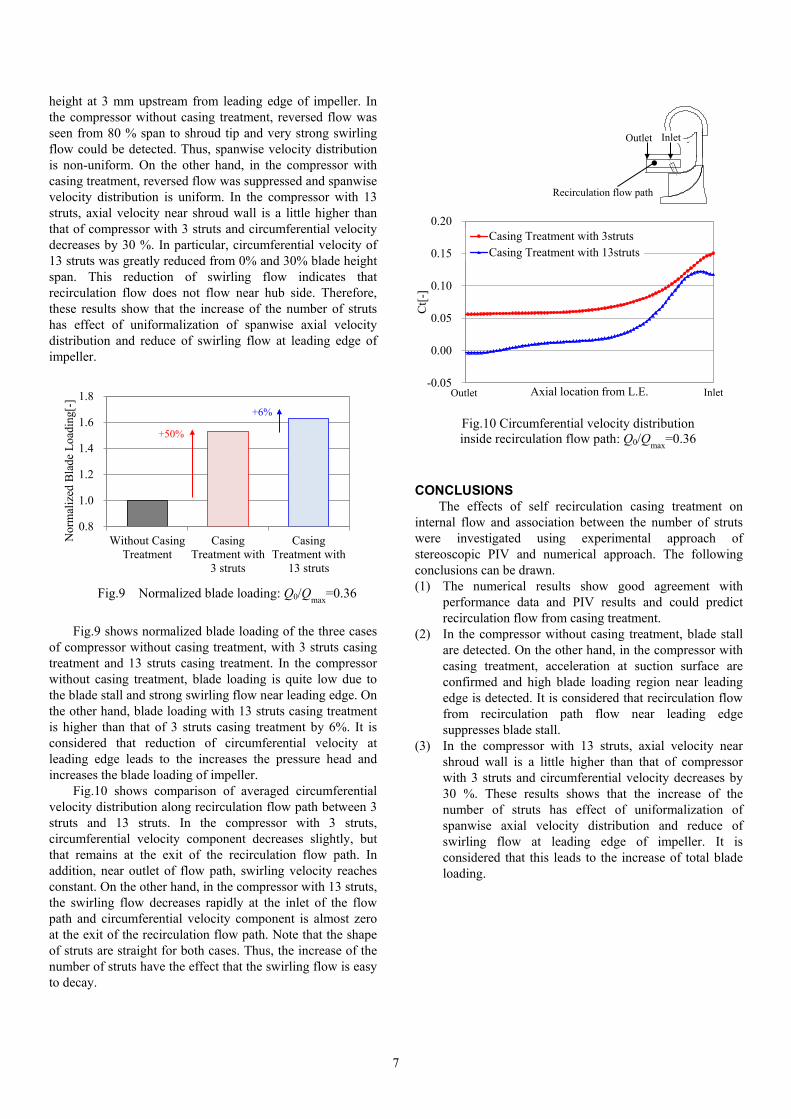
height at 3 mm upstream from leading edge of impeller. In the compressor without casing treatment, reversed flow was seen from 80 % span to shroud tip and very strong swirling flow could be detected. Thus, spanwise velocity distribution is non-uniform. On the other hand, in the compressor with casing treatment, reversed flow was suppressed and spanwise velocity distribution is uniform. In the compressor with 13 struts, axial velocity near shroud wall is a little higher than that of compressor with 3 struts and circumferential velocity decreases by 30 %. In particular, circumferential velocity of 13 struts was greatly reduced from 0% and 30% blade height span. This reduction of swirling flow indicates that recirculation flow does not flow near hub side. Therefore, these results show that the increase of the number of struts has effect of uniformalization of spanwise axial velocity distribution and reduce of swirling flow at leading edge of impeller.
Fig.9 shows normalized blade loading of the three cases of compressor without casing treatment, with 3 struts casing treatment and 13 struts casing treatment. In the compressor without casing treatment, blade loading is quite low due to the blade stall and strong swirling flow near leading edge. On the other hand, blade loading with 13 struts casing treatment is higher than that of 3 struts casing treatment by 6%. It is considered that reduction of circumferential velocity at leading edge leads to the increases the pressure head and increases the blade loading of impeller.
Fig.10 shows comparison of averaged circumferential velocity distribution along recirculation flow path between 3 struts and 13 struts. In the compressor with 3 struts, circumferential velocity component decreases slightly, but that remains at the exit of the recirculation flow path. In addition, near outlet of flow path, swirling velocity reaches constant. On the other hand, in the compressor with 13 struts, the swirling flow decreases rapidly at the inlet of the flow path and circumferential velocity component is almost zero at the exit of the recirculation flow path. Note that the shape of struts are straight for both cases. Thus, the increase of the number of struts have the effect that the swirling flow is easy to decay.
CONCLUSIONS The effects of self recirculation casing treatment on
internal flow and association between the number of struts were investigated using experimental approach of stereoscopic PIV and numerical approach. The following conclusions can be drawn. (1) The numerical results show good agreement with
performance data and PIV results and could predict recirculation flow from casing treatment.
(2) In the compressor without casing treatment, blade stall are detected. On the other hand, in the compressor with casing treatment, acceleration at suction surface are confirmed and high blade loading region near leading edge is detected. It is considered that recirculation flow from recirculation path flow near leading edge suppresses blade stall.
(3) In the compressor with 13 struts, axial velocity near shroud wall is a little higher than that of compressor with 3 struts and circumferential velocity decreases by 30 %. These results shows that the increase of the number of struts has effect of uniformalization of spanwise axial velocity distribution and reduce of swirling flow at leading edge of impeller. It is considered that this leads to the increase of total blade loading.
0.8
1.0
1.2
1.4
1.6
1.8
Without CasingTreatment
CasingTreatment with
3 struts
CasingTreatment with
13 struts
Nor
mal
ized
Bla
de L
oadi
ng[-
]
Fig.9 Normalized blade loading: Q0/Qmax=0.36
+50%
+6%
-0.05
0.00
0.05
0.10
0.15
0.20
Ct[-
]
Axial location from L.E.
Casing Treatment with 3strutsCasing Treatment with 13struts
Fig.10 Circumferential velocity distribution inside recirculation flow path: Q0/Qmax=0.36
Inlet Outlet
Outlet Inlet
Recirculation flow path
8
NOMENCLATURE Cm Normalized axial velocity [-] Ct Normalized circumferential velocity [-] N rotational speed of impeller [rpm] Q Air flow rate [m3/s] U Blade speed [m/s] Vθ Circumferential velocity [m/s] Vz Axial velocity [m/s] z Axial direction [m/s] Δt Time separation between the laser pulse [sec] Δx particle displacement [pixel] θ Camera angle [deg] π Total to total pressure ratio [-] πdesign Total to total pressure ratio at design point[-]
ACKNOWLEDGMENTS The author would like to thank Mr. Masaki Osako, Mr.
Yoshihiro Hayashi and Mr. Gou Toyoda for helping experimental works and data analyzing.
REFERENCES [1] Fisher, F. B., 1988, “Application of Map Width
Enhancement Devices to Turbocharger Compressor,” SAE paper 880794.
[2] Japikse, D., 1996, Centrifugal Compressor Design and Per-formance, Concepts ETI, Inc., Wilder, VT.
[3] Ibaraki, S., Ogita, H. and Yamada, T., 2007, “Development of a Wide Operating Range Turbocharger Compressor with a Low Solidity Vaned Difuuser,” CIMAC No. 166.
[4] An, B., Shiraishi, T., 2010, “Development of Variable Two-Stage Turbocharger for Passenger Cae Diesel Engines,” MHI Technical Review, Vol. 47, No. 4..
[5] Chen, H. and Lei, V., 2012, “Casing Treatment & Inlet Swirl of Centrifugal Compressors,” , Proceedings of ASME Turbo Expo 2012, GT2012-69340.
[6] Sivagnanasundaram, S., Spence, S. and Early, J., 2012, “Experimental and numerical analysis of a classical bleed slot system for a turbocharger compressor,” , 10th International conference on Turbocharging, IMechE, pp.325-341.
[7] Jung, S., Pelton, R., 2016, “Numerically Derived Design Guidelines of Self Recirculation Casing Treatment for Industrial Centrifugal Compressors,” Proceeding of ASME Turbo Expo 2016, GT2016-56672
[8] Tamaki, H., Zheng, X. and Zhang, Y., 2012, “Experimental Investigation of High Pressure Ratio Centrifugal Compressor with Axisymmetric and Non-Axisymmetric Recirculation De-vice,” Proceedings of ASME Turbo Expo 2012, GT2012-68219.
[9] Gancedo, M., Guillou, E. and Gutmark, E., 2013, “Experimental Investigation of Flow Instability in a Turbocharger Ported Shroud Compressor,” , Proceedings of ASME Turbo Expo 2013, GT2013-95134.


![[Date] - Grumman/Butkusgrummanbutkus.com/.../Draft_I2SL_Higher_Ed_Labs_Report.docx · Web viewTypically, the compressor loading of a chiller is varied using inlet vanes on the impeller](https://img.pdfslide.us/doc/110x75/5aabc9047f8b9a693f8c61ad/date-grumman-viewtypically-the-compressor-loading-of-a-chiller-is-varied-using.jpg)