Embed Size (px)
Citation preview
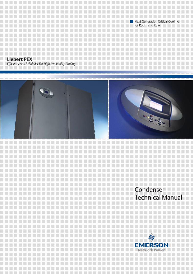
Next Generation Critical Coolingfor Room and Row
Liebert PEXEffi ciency And Reliability For High Availability Cooling
CondenserTechnical Manual
Liebert.PEX Condenser Technical Manual Version V1.0 Revision date May 27, 2010 BOM 31020761
Emerson Network Power provides customers with technical support. Users may contact the nearest Emerson local sales office or service center.
Copyright © 2010 by Emerson Network Power Co., Ltd.
All rights reserved. The contents in this document are subject to change without notice.
Emerson Network Power Co., Ltd.
Address: No.1 Kefa Rd., Science & Industry Park, Nanshan District 518057, Shenzhen China
Homepage: www.emersonnetworkpower.com.cn
E-mail: [email protected]

Contents
Chapter 1 Overview ............................................................................................................................................................ 1
1.1 Classification And Models..................................................................................................................................... 1 1.2 Model Description ................................................................................................................................................. 1 1.3 Appearance .......................................................................................................................................................... 1
Chapter 2 Technical Parameters......................................................................................................................................... 3
2.1 Environmental Parameters ................................................................................................................................... 3 2.1.1 Parameters Of Storage Environment......................................................................................................... 3 2.1.2 Parameters Of Operating Environment ..................................................................................................... 3 2.1.3 Signal Cable .............................................................................................................................................. 3
2.2 Mechanical Parameters ........................................................................................................................................ 4 2.2.1 Mechanical Parameters Of Condenser...................................................................................................... 4 2.2.2 Parameters Of Mounting Base .................................................................................................................. 5
2.3 Performance Parameters...................................................................................................................................... 6 2.3.1 Fan Design Parameters............................................................................................................................. 6 2.3.2 Heat Exchanging Capacity ........................................................................................................................ 7 2.3.3 SPL Parameters ........................................................................................................................................ 8 2.3.4 Configuration Parameters.......................................................................................................................... 9
Chapter 3 Fan Speed Controller ....................................................................................................................................... 10
3.1 Control Logic....................................................................................................................................................... 10 3.2 Wiring Terminal................................................................................................................................................... 11 3.3 HMI ..................................................................................................................................................................... 12 3.4 Operation Description Of HMI............................................................................................................................. 13 3.5 Protection Function ............................................................................................................................................. 16 3.6 Alarm Protection ................................................................................................................................................. 16
Chapter 4 Maintenance And Troubleshooting ................................................................................................................... 17
4.1 Maintenance ....................................................................................................................................................... 17 4.2 Troubleshooting .................................................................................................................................................. 19
Appendix 1 Condenser Matching Table ............................................................................................................................ 20
1. R22 Matching Table.............................................................................................................................................. 20 2. R407C Matching Table ......................................................................................................................................... 21
Appendix 2 Circuit Diagram............................................................................................................................................... 22
Appendix 3 Lifting Figure................................................................................................................................................... 24

Chapter 1 Overview 1
Chapter 1 Overview
The Liebert range of Air Cooled Condensers offer many unique benefits including low profile design, antirust aluminum cabinets, anticorrosive fins, low sound levels and efficient, reliable operation over a wide range of ambient conditions. To maximize performance and reduce downtime, the installation and commissioning of each unit must be carefully carried out.
This manual provides a guide to unit installation and commissioning. It should be read carefully before installation or commissioning commences. If an equipment defect is found, or if a malfunction occurs, it should be reported to your local sales office or distributor immediately.
Note: This manual refers only to standard production units. Units manufactured to a non-standard specification will generally be supplied with supplementary notes and drawings. Field alterations and/or external equipment alterations or connections are not covered by the Liebert product warranty.
This chapter gives a brief introduction to the classification & models, model description and appearance of the Liebert.PEX condenser (condenser for short).
1.1 Classification And Models
The condenser is classified into single circuit and dual circuit in 17 models. See Table 1-1 for details.
Table 1-1 Models
Type Model Single circuit LSF12, LSF18, LSF24, LSF32, LSF38, LSF42, LSF52, LSF62, LSF72, LSF76, LSF85 Dual circuit LDF42, LDF52, LDF62, LDF72, LDF76, LDF85
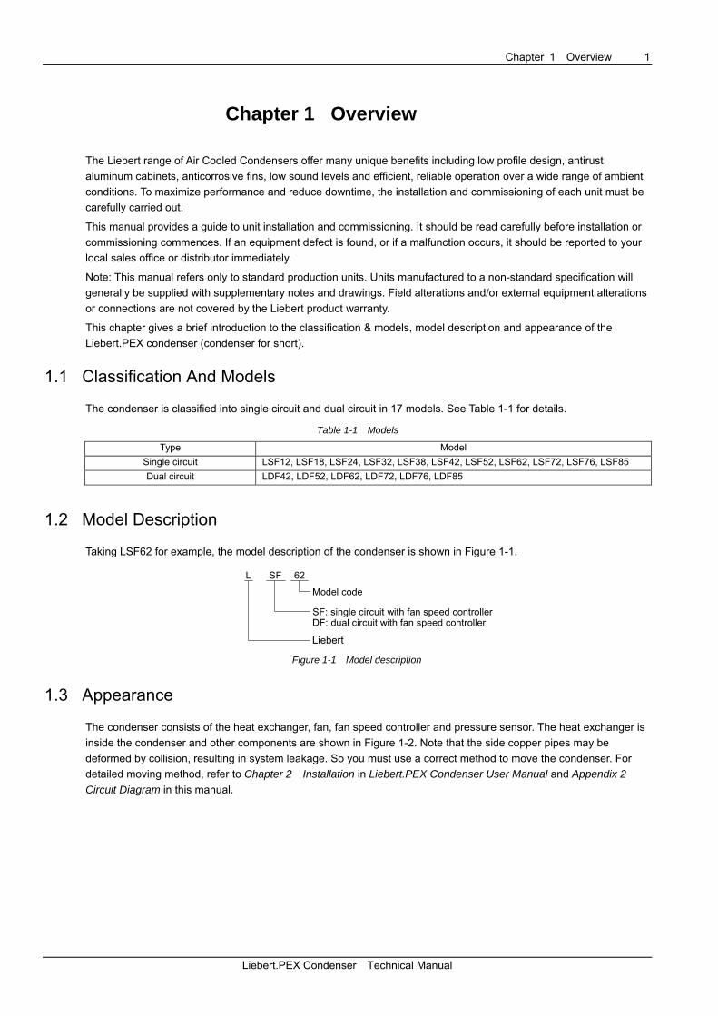
1.2 Model Description
Taking LSF62 for example, the model description of the condenser is shown in Figure 1-1.
L SF 62
Model code
SF: single circuit with fan speed controller
Liebert
DF: dual circuit with fan speed controller
Figure 1-1 Model description
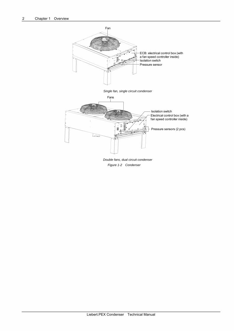
1.3 Appearance
The condenser consists of the heat exchanger, fan, fan speed controller and pressure sensor. The heat exchanger is inside the condenser and other components are shown in Figure 1-2. Note that the side copper pipes may be deformed by collision, resulting in system leakage. So you must use a correct method to move the condenser. For detailed moving method, refer to Chapter 2 Installation in Liebert.PEX Condenser User Manual and Appendix 2 Circuit Diagram in this manual.
Liebert.PEX Condenser Technical Manual
2 Chapter 1 Overview
Fan
ECB: electrical control box (witha fan speed controller inside)Isolation switchPressure sensor
Single fan, single circuit condenser
Fans
Pressure sensors (2 pcs)
Electrical control box (with afan speed controller inside)
Isolation switch
Double fans, dual circuit condenser
Figure 1-2 Condenser
Liebert.PEX Condenser Technical Manual
Chapter 2 Technical Parameters 3
Chapter 2 Technical Parameters
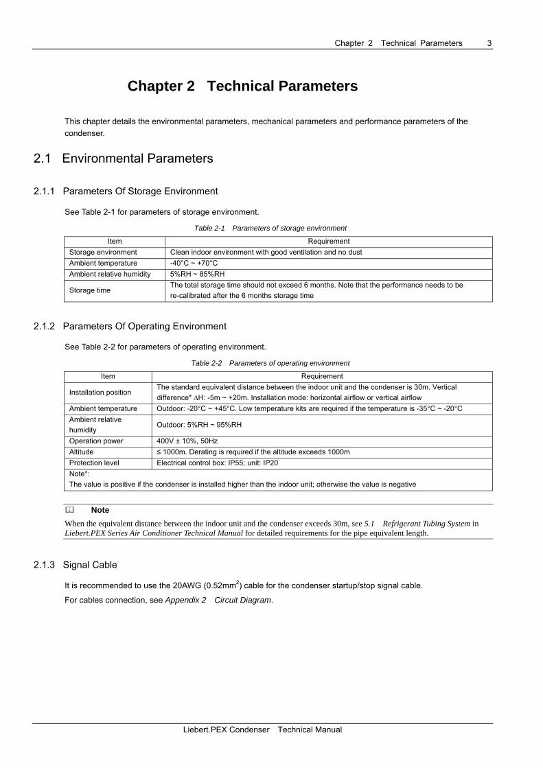
This chapter details the environmental parameters, mechanical parameters and performance parameters of the condenser.
2.1 Environmental Parameters
2.1.1 Parameters Of Storage Environment
See Table 2-1 for parameters of storage environment.
Table 2-1 Parameters of storage environment
Item Requirement Storage environment Clean indoor environment with good ventilation and no dust Ambient temperature -40°C ~ +70°C Ambient relative humidity 5%RH ~ 85%RH
Storage time The total storage time should not exceed 6 months. Note that the performance needs to be re-calibrated after the 6 months storage time
2.1.2 Parameters Of Operating Environment
See Table 2-2 for parameters of operating environment.
Table 2-2 Parameters of operating environment
Item Requirement
Installation position The standard equivalent distance between the indoor unit and the condenser is 30m. Vertical difference* ∆H: -5m ~ +20m. Installation mode: horizontal airflow or vertical airflow
Ambient temperature Outdoor: -20°C ~ +45°C. Low temperature kits are required if the temperature is -35°C ~ -20°C Ambient relative humidity
Outdoor: 5%RH ~ 95%RH
Operation power 400V ± 10%, 50Hz Altitude ≤ 1000m. Derating is required if the altitude exceeds 1000m Protection level Electrical control box: IP55; unit: IP20 Note*: The value is positive if the condenser is installed higher than the indoor unit; otherwise the value is negative
Note
When the equivalent distance between the indoor unit and the condenser exceeds 30m, see 5.1 Refrigerant Tubing System in Liebert.PEX Series Air Conditioner Technical Manual for detailed requirements for the pipe equivalent length.
2.1.3 Signal Cable
It is recommended to use the 20AWG (0.52mm2) cable for the condenser startup/stop signal cable.
For cables connection, see Appendix 2 Circuit Diagram.
Liebert.PEX Condenser Technical Manual
4 Chapter 2 Technical Parameters
2.2 Mechanical Parameters
2.2.1 Mechanical Parameters Of Condenser
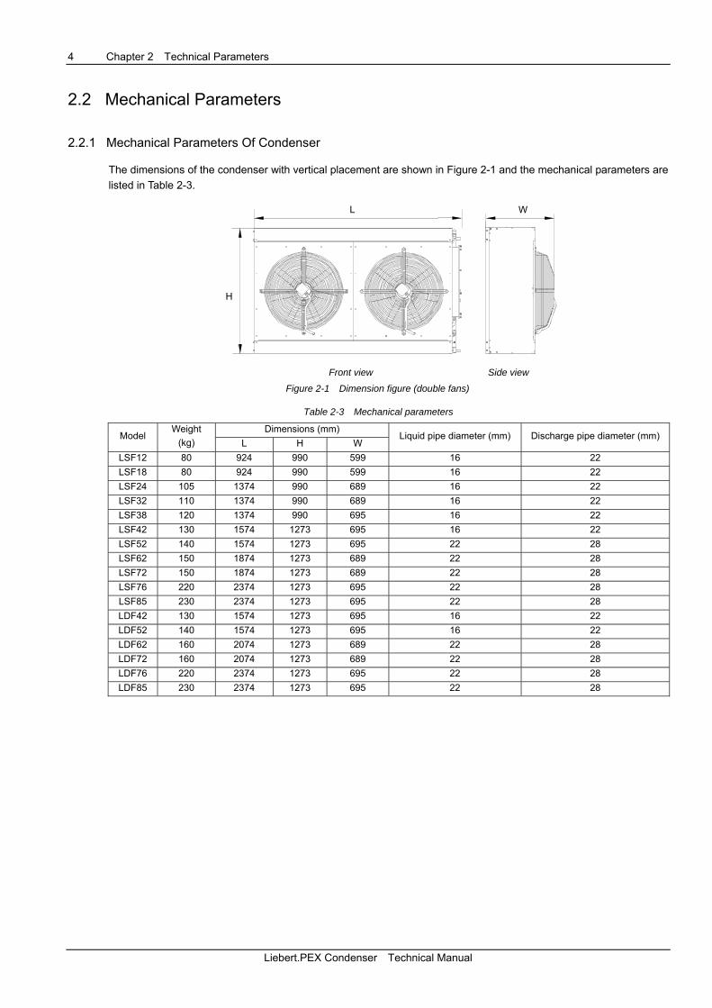
The dimensions of the condenser with vertical placement are shown in Figure 2-1 and the mechanical parameters are listed in Table 2-3.
W
H
LL
H
Front view Side view
Figure 2-1 Dimension figure (double fans)
Table 2-3 Mechanical parameters
Dimensions (mm) Model
Weight (kg) L H W
Liquid pipe diameter (mm) Discharge pipe diameter (mm)
LSF12 80 924 990 599 16 22 LSF18 80 924 990 599 16 22 LSF24 105 1374 990 689 16 22 LSF32 110 1374 990 689 16 22 LSF38 120 1374 990 695 16 22 LSF42 130 1574 1273 695 16 22 LSF52 140 1574 1273 695 22 28 LSF62 150 1874 1273 689 22 28 LSF72 150 1874 1273 689 22 28 LSF76 220 2374 1273 695 22 28 LSF85 230 2374 1273 695 22 28 LDF42 130 1574 1273 695 16 22 LDF52 140 1574 1273 695 16 22 LDF62 160 2074 1273 689 22 28 LDF72 160 2074 1273 689 22 28 LDF76 220 2374 1273 695 22 28 LDF85 230 2374 1273 695 22 28
Liebert.PEX Condenser Technical Manual
Chapter 2 Technical Parameters 5
2.2.2 Parameters Of Mounting Base
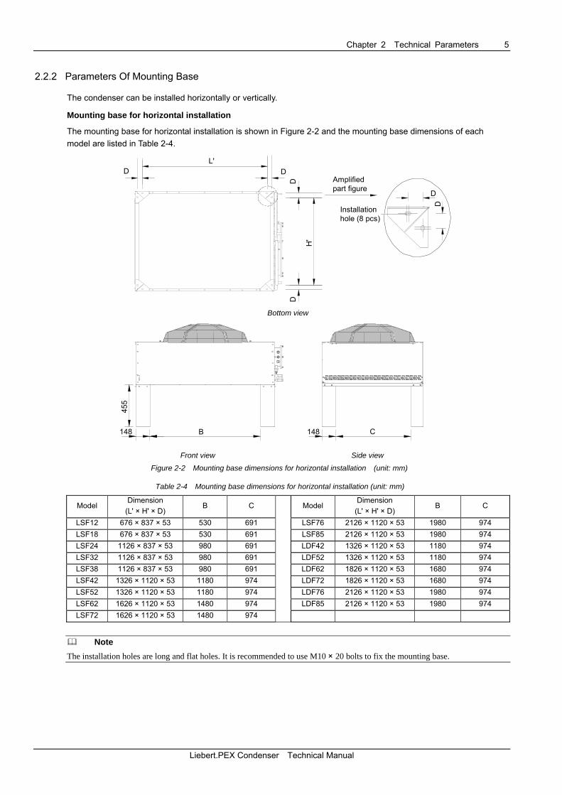
The condenser can be installed horizontally or vertically.
Mounting base for horizontal installation
The mounting base for horizontal installation is shown in Figure 2-2 and the mounting base dimensions of each model are listed in Table 2-4.
D DL'
D
H'
D
D
D
Amplifiedpart figure
Installationhole (8 pcs)
Bottom view
455
455
148 B
148 C
Front view Side view
Figure 2-2 Mounting base dimensions for horizontal installation (unit: mm)
Table 2-4 Mounting base dimensions for horizontal installation (unit: mm)
Model Dimension
(L' × H' × D) B C Model
Dimension (L' × H' × D)
B C
LSF12 676 × 837 × 53 530 691 LSF76 2126 × 1120 × 53 1980 974 LSF18 676 × 837 × 53 530 691 LSF85 2126 × 1120 × 53 1980 974 LSF24 1126 × 837 × 53 980 691 LDF42 1326 × 1120 × 53 1180 974 LSF32 1126 × 837 × 53 980 691 LDF52 1326 × 1120 × 53 1180 974 LSF38 1126 × 837 × 53 980 691 LDF62 1826 × 1120 × 53 1680 974 LSF42 1326 × 1120 × 53 1180 974 LDF72 1826 × 1120 × 53 1680 974 LSF52 1326 × 1120 × 53 1180 974 LDF76 2126 × 1120 × 53 1980 974 LSF62 1626 × 1120 × 53 1480 974 LDF85 2126 × 1120 × 53 1980 974 LSF72 1626 × 1120 × 53 1480 974
Note The installation holes are long and flat holes. It is recommended to use M10 × 20 bolts to fix the mounting base.
Liebert.PEX Condenser Technical Manual
6 Chapter 2 Technical Parameters
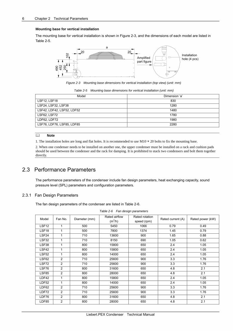
Mounting base for vertical installation
The mounting base for vertical installation is shown in Figure 2-3, and the dimensions of each model are listed in Table 2-5.
250
102
452
490
a2020
Installationhole (4 pcs)Amplified
part figure
Figure 2-3 Mounting base dimensions for vertical installation (top view) (unit: mm)
Table 2-5 Mounting base dimensions for vertical installation (unit: mm)
Model Dimension ‘a’ LSF12, LSF18 830 LSF24, LSF32, LSF38 1280 LSF42, LDF42, LSF52, LDF52 1480 LSF62, LSF72 1780 LDF62, LDF72 1980 LSF76, LDF76, LSF85, LDF85 2280
Note 1. The installation holes are long and flat holes. It is recommended to use M10 × 20 bolts to fix the mounting base. 2. When one condenser needs to be installed on another one, the upper condenser must be installed on a rack and cushion pads should be used between the condenser and the rack for damping. It is prohibited to stack two condensers and bolt them together directly.
2.3 Performance Parameters
The performance parameters of the condenser include fan design parameters, heat exchanging capacity, sound pressure level (SPL) parameters and configuration parameters.
2.3.1 Fan Design Parameters
The fan design parameters of the condenser are listed in Table 2-6.
Table 2-6 Fan design parameters
Model Fan No. Diameter (mm) Rated airflow
(m3/h) Rated rotation speed (rpm)
Rated current (A) Rated power (kW)
LSF12 1 500 5450 1066 0.79 0.49 LSF18 1 500 7800 1374 1.45 0.79 LSF24 1 710 13600 900 1.65 0.88 LSF32 1 710 8150 690 1.05 0.62 LSF38 1 800 15800 650 2.4 1.05 LSF42 1 800 15800 650 2.4 1.05 LSF52 1 800 14000 650 2.4 1.05 LSF62 2 710 25600 900 3.3 1.76 LSF72 2 710 25600 900 3.3 1.76 LSF76 2 800 31600 650 4.8 2.1 LSF85 2 800 28000 650 4.8 2.1 LDF42 1 800 15800 650 2.4 1.05 LDF52 1 800 14000 650 2.4 1.05 LDF62 2 710 25600 900 3.3 1.76 LDF72 2 710 25600 900 3.3 1.76 LDF76 2 800 31600 650 4.8 2.1 LDF85 2 800 28000 650 4.8 2.1
Liebert.PEX Condenser Technical Manual
Chapter 2 Technical Parameters 7
Note 1. The rated airflow, rated rotation speed, rated current and rated power are the parameters of the fan operating at 400V, which is provided by the factory. 2. The power supply of the condenser, as determined by the rated current in Table 2-6, is provided by yourself on site.
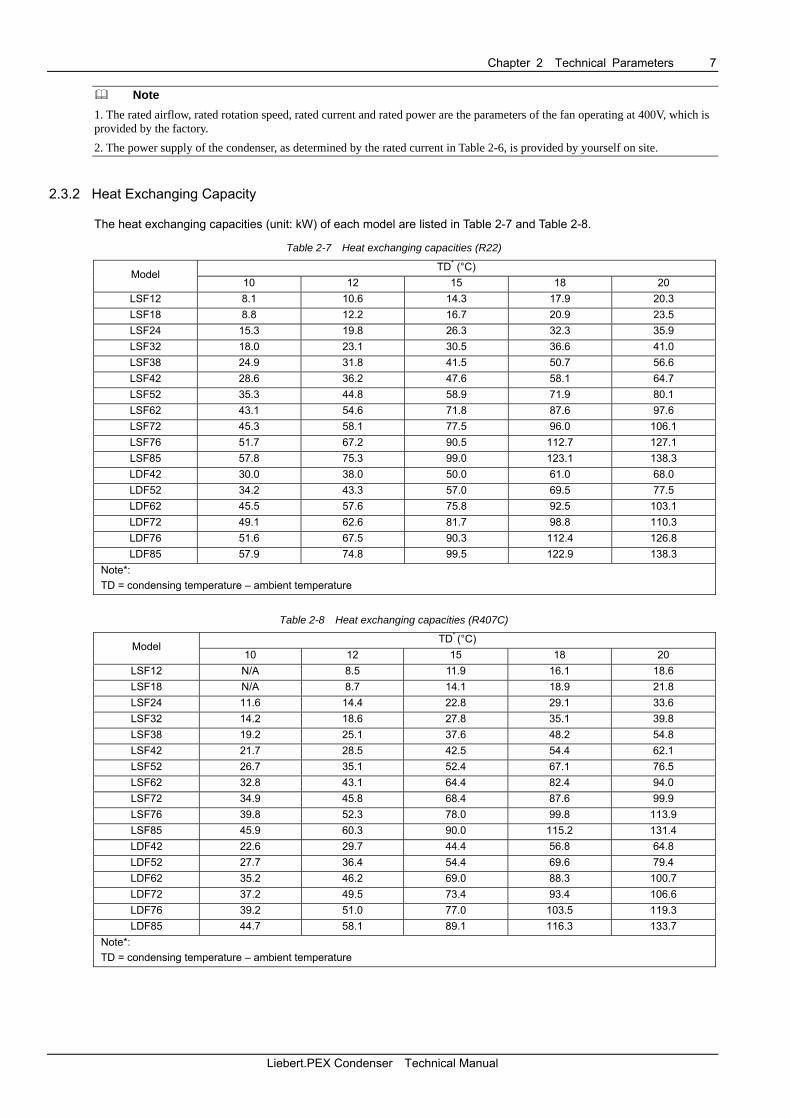
2.3.2 Heat Exchanging Capacity
The heat exchanging capacities (unit: kW) of each model are listed in Table 2-7 and Table 2-8.
Table 2-7 Heat exchanging capacities (R22)
TD* (°C) Model
10 12 15 18 20 LSF12 8.1 10.6 14.3 17.9 20.3 LSF18 8.8 12.2 16.7 20.9 23.5 LSF24 15.3 19.8 26.3 32.3 35.9 LSF32 18.0 23.1 30.5 36.6 41.0 LSF38 24.9 31.8 41.5 50.7 56.6 LSF42 28.6 36.2 47.6 58.1 64.7 LSF52 35.3 44.8 58.9 71.9 80.1 LSF62 43.1 54.6 71.8 87.6 97.6 LSF72 45.3 58.1 77.5 96.0 106.1 LSF76 51.7 67.2 90.5 112.7 127.1 LSF85 57.8 75.3 99.0 123.1 138.3 LDF42 30.0 38.0 50.0 61.0 68.0 LDF52 34.2 43.3 57.0 69.5 77.5 LDF62 45.5 57.6 75.8 92.5 103.1 LDF72 49.1 62.6 81.7 98.8 110.3 LDF76 51.6 67.5 90.3 112.4 126.8 LDF85 57.9 74.8 99.5 122.9 138.3
Note*: TD = condensing temperature – ambient temperature
Table 2-8 Heat exchanging capacities (R407C)
TD* (°C) Model
10 12 15 18 20 LSF12 N/A 8.5 11.9 16.1 18.6 LSF18 N/A 8.7 14.1 18.9 21.8 LSF24 11.6 14.4 22.8 29.1 33.6 LSF32 14.2 18.6 27.8 35.1 39.8 LSF38 19.2 25.1 37.6 48.2 54.8 LSF42 21.7 28.5 42.5 54.4 62.1 LSF52 26.7 35.1 52.4 67.1 76.5 LSF62 32.8 43.1 64.4 82.4 94.0 LSF72 34.9 45.8 68.4 87.6 99.9 LSF76 39.8 52.3 78.0 99.8 113.9 LSF85 45.9 60.3 90.0 115.2 131.4 LDF42 22.6 29.7 44.4 56.8 64.8 LDF52 27.7 36.4 54.4 69.6 79.4 LDF62 35.2 46.2 69.0 88.3 100.7 LDF72 37.2 49.5 73.4 93.4 106.6 LDF76 39.2 51.0 77.0 103.5 119.3 LDF85 44.7 58.1 89.1 116.3 133.7
Note*: TD = condensing temperature – ambient temperature
Liebert.PEX Condenser Technical Manual
8 Chapter 2 Technical Parameters
2.3.3 SPL Parameters
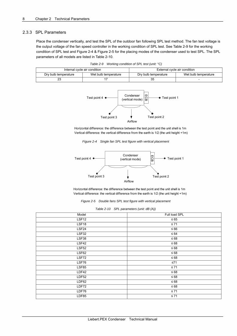
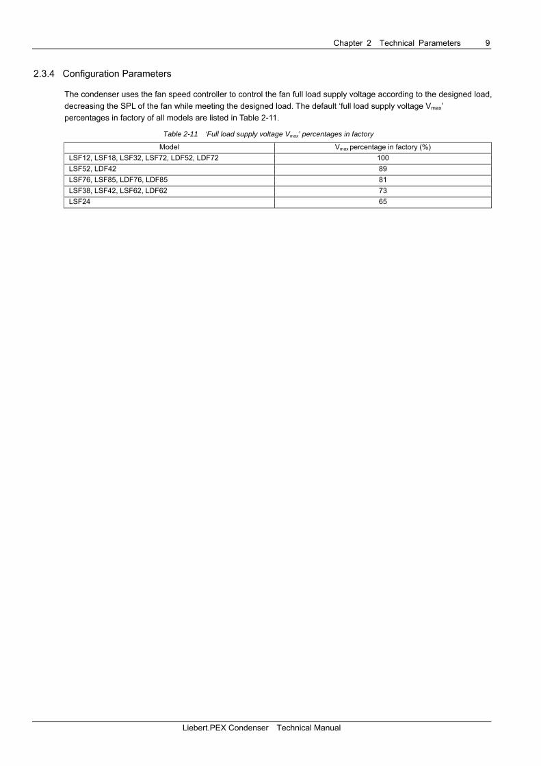
Place the condenser vertically, and test the SPL of the outdoor fan following SPL test method. The fan test voltage is the output voltage of the fan speed controller in the working condition of SPL test. See Table 2-9 for the working condition of SPL test and Figure 2-4 & Figure 2-5 for the placing modes of the condenser used to test SPL. The SPL parameters of all models are listed in Table 2-10.
Table 2-9 Working condition of SPL test (unit: °C)
Internal cycle air condition External cycle air condition Dry bulb temperature Wet bulb temperature Dry bulb temperature Wet bulb temperature
23 17 35 -
Airflow
Test point 1
Test point 2Test point 3
Test point 4Condenser
(vertical mode)
Horizontal difference: the difference between the test point and the unit shell is 1mVertical difference: the vertical difference from the earth is 1/2 (the unit height +1m)
EC
B
Figure 2-4 Single fan SPL test figure with vertical placement
Airflow
Test point 1
Test point 2Test point 3
Test point 4Condenser
(vertical mode)
Horizontal difference: the difference between the test point and the unit shell is 1mVertical difference: the vertical difference from the earth is 1/2 (the unit height +1m)
EC
B
Figure 2-5 Double fans SPL test figure with vertical placement
Table 2-10 SPL parameters (unit: dB (A))
Model Full load SPL LSF12 ≤ 65 LSF18 ≤ 71 LSF24 ≤ 66 LSF32 ≤ 64 LSF38 ≤ 68 LSF42 ≤ 68 LSF52 ≤ 68 LSF62 ≤ 68 LSF72 ≤ 68 LSF76 ≤71 LSF85 ≤ 71 LDF42 ≤ 68 LDF52 ≤ 68 LDF62 ≤ 68 LDF72 ≤ 68 LDF76 ≤ 71 LDF85 ≤ 71
Liebert.PEX Condenser Technical Manual
Chapter 2 Technical Parameters 9
2.3.4 Configuration Parameters
The condenser uses the fan speed controller to control the fan full load supply voltage according to the designed load, decreasing the SPL of the fan while meeting the designed load. The default ‘full load supply voltage Vmax’ percentages in factory of all models are listed in Table 2-11.
Table 2-11 ‘Full load supply voltage Vmax’ percentages in factory
Model Vmax percentage in factory (%) LSF12, LSF18, LSF32, LSF72, LDF52, LDF72 100 LSF52, LDF42 89 LSF76, LSF85, LDF76, LDF85 81 LSF38, LSF42, LSF62, LDF62 73 LSF24 65
Liebert.PEX Condenser Technical Manual
10 Chapter 3 Fan Speed Controller
Chapter 3 Fan Speed Controller
This chapter details the fan speed controller, including control logic, wiring terminal, human-machine interface (HMI), HMI operation, protection function and alarm function.
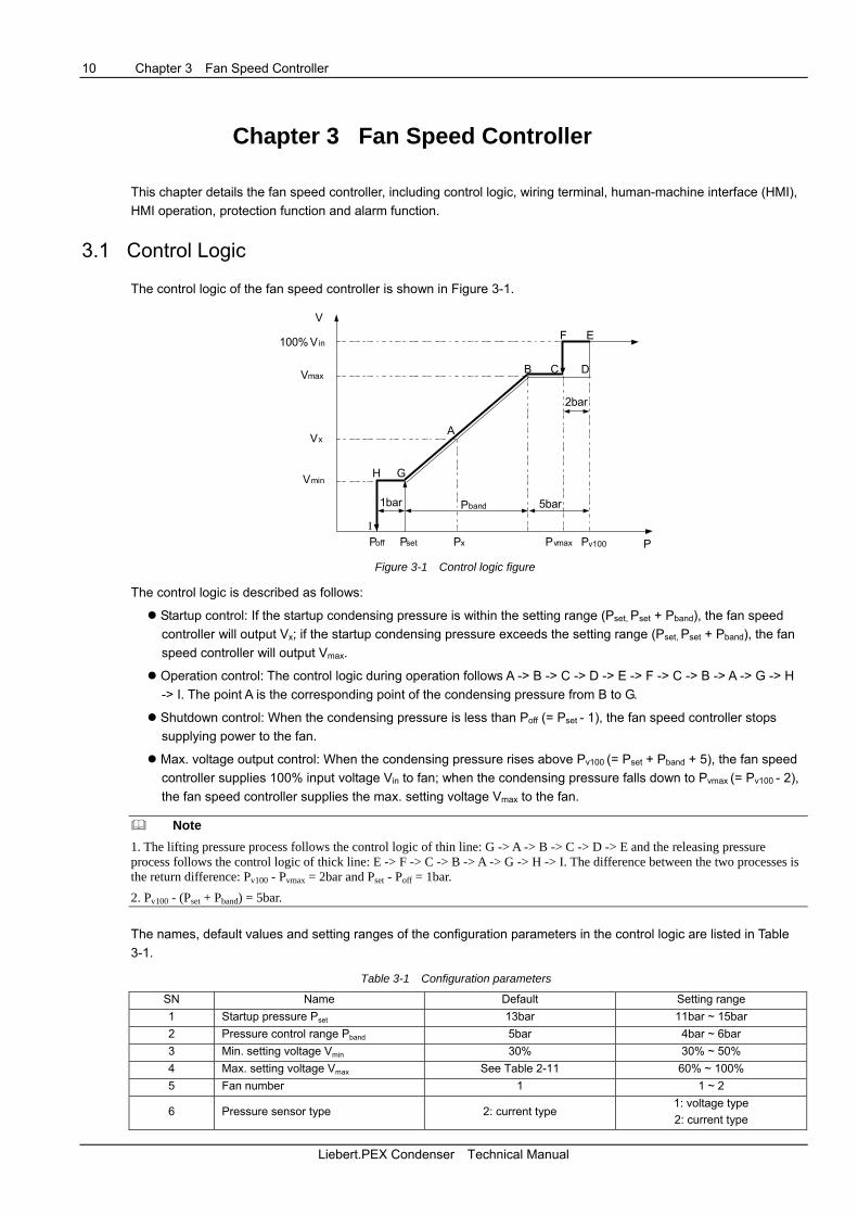
3.1 Control Logic
The control logic of the fan speed controller is shown in Figure 3-1.
V
PPoff Pset Pvmax Pv100
100% Vin
Vmax
Vmin
Vx
Px
A
B C D
EF
GH
I
2bar
1bar 5barPband
Figure 3-1 Control logic figure
The control logic is described as follows:
Startup control: If the startup condensing pressure is within the setting range (Pset, Pset + Pband), the fan speed controller will output Vx; if the startup condensing pressure exceeds the setting range (Pset, Pset + Pband), the fan speed controller will output Vmax.
Operation control: The control logic during operation follows A -> B -> C -> D -> E -> F -> C -> B -> A -> G -> H -> I. The point A is the corresponding point of the condensing pressure from B to G.
Shutdown control: When the condensing pressure is less than Poff (= Pset - 1), the fan speed controller stops supplying power to the fan.
Max. voltage output control: When the condensing pressure rises above Pv100 (= Pset + Pband + 5), the fan speed controller supplies 100% input voltage Vin to fan; when the condensing pressure falls down to Pvmax (= Pv100 - 2), the fan speed controller supplies the max. setting voltage Vmax to the fan.
Note 1. The lifting pressure process follows the control logic of thin line: G -> A -> B -> C -> D -> E and the releasing pressure process follows the control logic of thick line: E -> F -> C -> B -> A -> G -> H -> I. The difference between the two processes is the return difference: Pv100 - Pvmax = 2bar and Pset - Poff = 1bar. 2. Pv100 - (Pset + Pband) = 5bar. The names, default values and setting ranges of the configuration parameters in the control logic are listed in Table 3-1.
Table 3-1 Configuration parameters
SN Name Default Setting range 1 Startup pressure Pset 13bar 11bar ~ 15bar 2 Pressure control range Pband 5bar 4bar ~ 6bar 3 Min. setting voltage Vmin 30% 30% ~ 50% 4 Max. setting voltage Vmax See Table 2-11 60% ~ 100% 5 Fan number 1 1 ~ 2
6 Pressure sensor type 2: current type 1: voltage type 2: current type
Liebert.PEX Condenser Technical Manual
Chapter 3 Fan Speed Controller 11
Note 1. The configured fan number must be the same as the number of the actual fans. Otherwise, a false alarm will appear. 2. The configured type of the pressure sensor must be the same as the actual type. Otherwise, the pressure will not be measured accurately, and the deviation will be increased during the control process.
3.2 Wiring Terminal
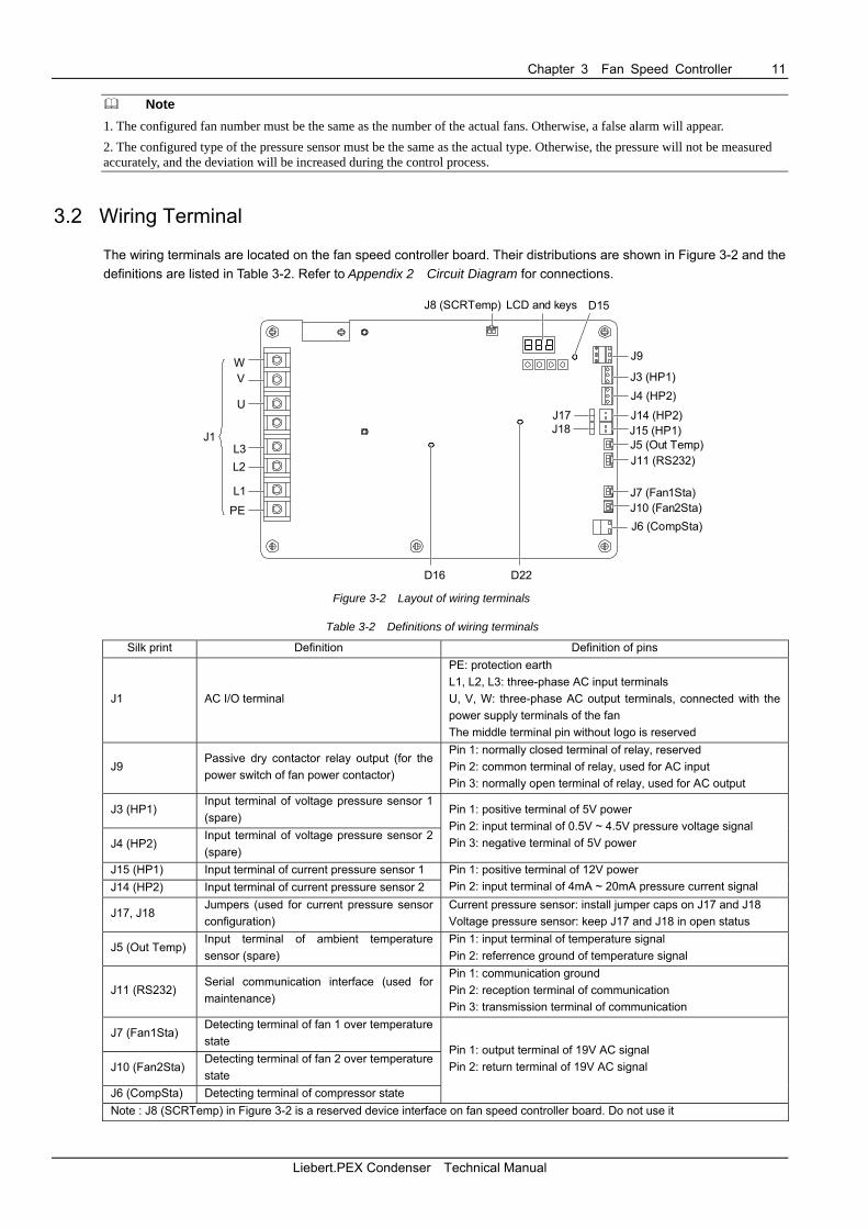
The wiring terminals are located on the fan speed controller board. Their distributions are shown in Figure 3-2 and the definitions are listed in Table 3-2. Refer to Appendix 2 Circuit Diagram for connections.
J9
J3 (HP1)J4 (HP2)
J14 (HP2)J15 (HP1)J5 (Out Temp)J11 (RS232)
J7 (Fan1Sta)J10 (Fan2Sta)J6 (CompSta)
WV
U
L3
L1
L2
PE
J8 (SCRTemp)
J17J18
J1
D16 D22
D15LCD and keys
Figure 3-2 Layout of wiring terminals
Table 3-2 Definitions of wiring terminals
Silk print Definition Definition of pins
J1 AC I/O terminal
PE: protection earth L1, L2, L3: three-phase AC input terminals U, V, W: three-phase AC output terminals, connected with the power supply terminals of the fan The middle terminal pin without logo is reserved
J9 Passive dry contactor relay output (for the power switch of fan power contactor)
Pin 1: normally closed terminal of relay, reserved Pin 2: common terminal of relay, used for AC input Pin 3: normally open terminal of relay, used for AC output
J3 (HP1) Input terminal of voltage pressure sensor 1 (spare)
J4 (HP2) Input terminal of voltage pressure sensor 2 (spare)
Pin 1: positive terminal of 5V power Pin 2: input terminal of 0.5V ~ 4.5V pressure voltage signal Pin 3: negative terminal of 5V power
J15 (HP1) Input terminal of current pressure sensor 1 J14 (HP2) Input terminal of current pressure sensor 2
Pin 1: positive terminal of 12V power Pin 2: input terminal of 4mA ~ 20mA pressure current signal
J17, J18 Jumpers (used for current pressure sensor configuration)
Current pressure sensor: install jumper caps on J17 and J18 Voltage pressure sensor: keep J17 and J18 in open status
J5 (Out Temp) Input terminal of ambient temperature sensor (spare)
Pin 1: input terminal of temperature signal Pin 2: referrence ground of temperature signal
J11 (RS232) Serial communication interface (used for maintenance)
Pin 1: communication ground Pin 2: reception terminal of communication Pin 3: transmission terminal of communication
J7 (Fan1Sta) Detecting terminal of fan 1 over temperature state
J10 (Fan2Sta) Detecting terminal of fan 2 over temperature state
J6 (CompSta) Detecting terminal of compressor state
Pin 1: output terminal of 19V AC signal Pin 2: return terminal of 19V AC signal
Note : J8 (SCRTemp) in Figure 3-2 is a reserved device interface on fan speed controller board. Do not use it
Liebert.PEX Condenser Technical Manual
12 Chapter 3 Fan Speed Controller
Note 1. If the phase sequence of the three-phase AC inputs (L1, L2 and L3) is incorrect, the fan speed controller will generate a phase loss alarm A00 and cannot supply the AC output. 2. If the phase sequence of the three-phase AC outputs (U, V and W) is incorrect, the fan will rotate in the reverse direction. 3. If the upper temperature detecting terminals of the fan 1 & 2 (J7, J10), and the detecting terminal of the compressor (J6) are not connected with cables, you can short them with short cables to make sure that the fan speed controller can operate normally. If the terminals are disconnected, the fan speed controller cannot supply the AC output.
3.3 HMI
The fan speed controller operation and setup is provided through indicators, RS232 serial port, keys and LED.
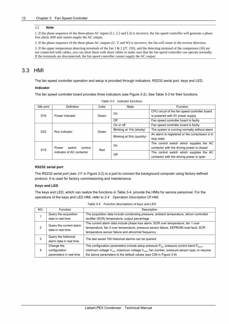
Indicator
The fan speed controller board provides three indicators (see Figure 3-2). See Table 3-3 for their functions.
Table 3-3 Indicator functions
Silk print Definition Color State Function
On CPU circuit of the fan speed controller board is powered with 5V power supply D16 Power indicator Green
Off Fan speed controller board is faulty On or off Fan speed controller board is faulty Blinking at 1Hz (slowly) The system is running normally without alarm
D22 Run indicator Green Blinking at 5Hz (quickly)
An alarm is registered or the compressor is in stop state
On The control switch which supplies the AC contactor with the driving power is closed
D15 Power switch control indicator of AC contactor
Red Off
The control switch which supplies the AC contactor with the driving power is open
RS232 serial port
The RS232 serial port (see J11 in Figure 3-2) is a port to connect the background computer using factory-defined protocol. It is used for factory commissioning and maintenance.
Keys and LED
The keys and LED, which can realize the functions in Table 3-4, provide the HMIs for service personnel. For the operations of the keys and LED HMI, refer to 3.4 Operation Description Of HMI.
Table 3-4 Function descriptions of keys and LED
NO. Function Description
1 Query the acquisition data in real time
The acquisition data include condensing pressure, ambient temperature, silicon controlled rectifier (SCR) temperature, output percentage
2 Query the current alarm data in real time
The current alarm data include phase loss alarm, SCR over temperature, fan 1 over temperature, fan 2 over temperature, pressure sensor failure, EEPROM read fault, SCR temperature sensor failure and abnormal frequency
3 Query the historical alarm data in real time
The last saved 100 historical alarms can be queried
4 Change the configuration parameters in real time
The configuration parameters include setup pressure Pset, pressure control band Pband, minimum voltage Vmin, maximum voltage Vmax, fan number, pressure sensor type; or resume the above parameters to the default values (see C99 in Figure 3-9)
Liebert.PEX Condenser Technical Manual
Chapter 3 Fan Speed Controller 13
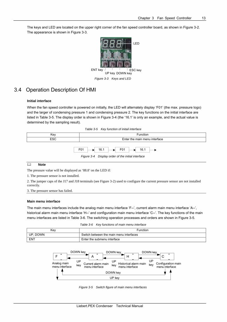
The keys and LED are located on the upper right corner of the fan speed controller board, as shown in Figure 3-2. The appearance is shown in Figure 3-3.
LCD
ENT keyDOWN key
ESC keyUP key
LED
Figure 3-3 Keys and LED
3.4 Operation Description Of HMI
Initial interface
When the fan speed controller is powered on initially, the LED will alternately display ‘F01’ (the max. pressure logo) and the larger of condensing pressure 1 and condensing pressure 2. The key functions on the initial interface are listed in Table 3-5. The display order is shown in Figure 3-4 (the ‘16.1’ is only an example, and the actual value is determined by the sampling result).
Table 3-5 Key function of initail interface
Key Function ESC Enter the main menu interface
F01 16.1 F01 16.1
Figure 3-4 Display order of the initial interface
Note The pressure value will be displayed as ‘88.8’ on the LED if: 1. The pressure sensor is not installed. 2. The jumper caps of the J17 and J18 terminals (see Figure 3-2) used to configure the current pressure sensor are not installed correctly. 3. The pressure sensor has failed. Main menu interface
The main menu interfaces include the analog main menu interface ‘F--’, current alarm main menu interface ‘A--’, historical alarm main menu interface ‘H--’ and configuration main menu interface ‘C--’. The key functions of the main menu interfaces are listed in Table 3-6. The switching operation processes and orders are shown in Figure 3-5.
Table 3-6 Key functions of main menu interface
Key Function UP, DOWN Switch between the main menu interfaces ENT Enter the submenu interface
F A H CDOWN keyDOWN keyDOWN key
UPkey
UPkey
UPkey
DOWN key
UP key
Configuration mainAnalog main Current alarm main Historical alarm mainmenu interface menu interface menu interface
--
--
--
--
menu interface
Figure 3-5 Switch figure of main menu interfaces
Liebert.PEX Condenser Technical Manual
14 Chapter 3 Fan Speed Controller
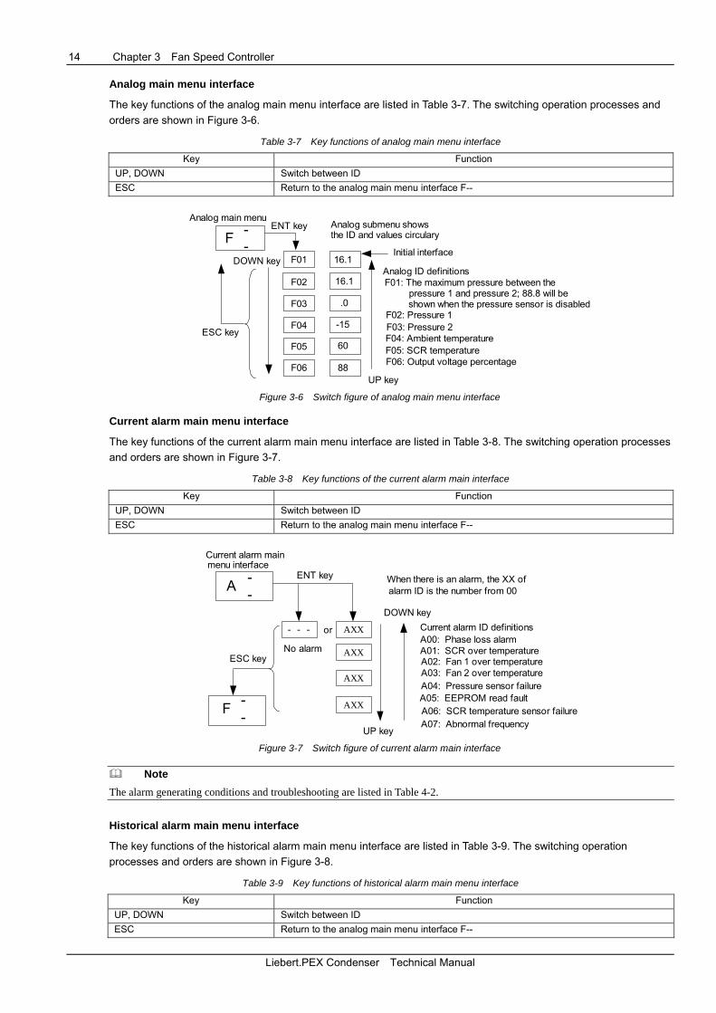
Analog main menu interface
The key functions of the analog main menu interface are listed in Table 3-7. The switching operation processes and orders are shown in Figure 3-6.
Table 3-7 Key functions of analog main menu interface
Key Function UP, DOWN Switch between ID ESC Return to the analog main menu interface F--
ENT key
DOWN key
ESC key
UP key
F --
F01
F02
F03
F04
F05
F06
16.1
16.1
.0
-15
60
88
Analog main menuAnalog submenu shows
Initial interface
Analog ID definitionsF01: The maximum pressure between the
F02: Pressure 1F03: Pressure 2F04: Ambient temperatureF05: SCR temperatureF06: Output voltage percentage
pressure 1 and pressure 2; 88.8 will beshown when the pressure sensor is disabled
the ID and values circulary
Figure 3-6 Switch figure of analog main menu interface
Current alarm main menu interface
The key functions of the current alarm main menu interface are listed in Table 3-8. The switching operation processes and orders are shown in Figure 3-7.
Table 3-8 Key functions of the current alarm main interface
Key Function UP, DOWN Switch between ID ESC Return to the analog main menu interface F--
No alarm
Current alarm main
ENT key
ESC key
UP key
DOWN keyCurrent alarm ID definitionsA00: Phase loss alarmA01: SCR over temperatureA02: Fan 1 over temperatureA03: Fan 2 over temperatureA04: Pressure sensor failureA05: EEPROM read faultA06: SCR temperature sensor failureA07: Abnormal frequency
A --
F --
- - - AXX
AXX
AXX
AXX
or
When there is an alarm, the XX of menu interface
alarm ID is the number from 00
Figure 3-7 Switch figure of current alarm main interface
Note The alarm generating conditions and troubleshooting are listed in Table 4-2. Historical alarm main menu interface
The key functions of the historical alarm main menu interface are listed in Table 3-9. The switching operation processes and orders are shown in Figure 3-8.
Table 3-9 Key functions of historical alarm main menu interface
Key Function UP, DOWN Switch between ID ESC Return to the analog main menu interface F--
Liebert.PEX Condenser Technical Manual

Chapter 3 Fan Speed Controller 15
H - -
F - -
1.X
2.X
99.X
0.X
Historical alarm ID definitions
1: SCR over temperature2: Fan 1 over temperature3: Fan 2 over temperature4: Pressure sensor failure
6: SCR temperature sensor failure7: Abnormal frequency
5: EEPROM read fault
0: Phase loss alarm
Historical alarm mainmenu interface
ESC key
UP key
DOWN key
-: No alarmAnalog main menu
ENT key
The radix point is the space mark between the number order andalarm ID. The number is the alarm number and from1 whcih isthe present historical alarm. 0 is the 100th historical alarm. X isthe historical alarm ID. When there is no alarm, '-' will be shown
Figure 3-8 Switch figure of historical alarm main menu interface
Configuration main menu interface
Note The configuration main menu interface is designed only for maintenance personnel to set parameters, others are prohibited to operate it. The key functions of the configuration main menu interface are listed in Table 3-10. The switching operation processes and orders are shown in Figure 3-9.
Table 3-10 Key functions of configuration main menu interface
Key Function
UP, DOWN 1. Switch between ID 2. Change the ID value
ENT 1. Enter the changing interface of ID value 2. Confirm the changed ID value
ESC
1. Return to the configuration main menu interface C-- 2. Return to the configuration value change submenu interface from the configuration ID selected submenu interface 3. Return to the configuration value change submenu interface from the prompt interface ‘888’ of successful change
C01
C02
C03
C04
C05
C06
C99
888
13
4
30
100
1
2
C - -
Configuration mainmenu interface
UP key
DOWN key
ESC key
ESC keyENT key
ESC key
ENT key
ENT key
Configuration IDselected submenu
Configuration valuechanged submenu (using
DOWN and UP keys)
C01: Pressure set PsetC02: Pressure band PbandC03: Minimum voltage VminC04: Maximum voltage VmaxC05: Fan numberC06: Sensor typeC99: Resume the default
Configuration ID definitions
Prompt interface ofsuccessful change
Figure 3-9 Switch figure of configuration data main menu interface
Liebert.PEX Condenser Technical Manual
16 Chapter 3 Fan Speed Controller
3.5 Protection Function
The fan speed controller can provide a corresponding protection function according to the acquired information. The detailed protection functions are as follows:
Compressor operation synchronization protection
When the compressor operates normally, the fan speed controller can provide an output control according to the measured condensing pressure. Otherwise, the fan power will be stopped.
Fan power protection 1
Before starting the fan power output, if the AC abnormal frequency alarm (the normal range of AC frequency is 45Hz ~ 65Hz) is detected, the fan power output will be stopped until the AC frequency resumes normal.
Fan power protection 2
If a fault such as fan over temperature, phase loss alarm or SCR over temperature occurs during single fan configuration, the fan power output will be stopped until the fault is removed. When the temperature rises up to 100°C, the SCR will cut off the fan power; when the temperature drops down to 70°C, the fan power will be restored.
Fan power protection 3
When a single fan is configured, if the interval between two consecutive over temperature alarms of fan 1 is less than 24 hours, the power of fan contactor coil will be cut off and the fan power output will be stopped. After the maintenance personnel remove the faults and restart the fan speed controller, the fan re-works.
When two fans are configured, if the interval between two consecutive over temperature alarms of both fan 1 and fan 2 is less than 24 hours, the power of fan contactor coil will be cut off and the fan power output will be stopped. After the maintenance personnel remove the faults and restart the fan speed controller, the fans re-work.
3.6 Alarm Protection
The fan speed controller can handle the corresponding alarms according to the acquired alarm information. The detailed alarms include:
1. Phase loss alarm 2. SCR over temperature 3. Fan 1 over temperature
4. Fan 2 over temperature 5. Pressure sensor failure 6. EEPROM read fault
7. SCR temperature sensor failure 8. Abnormal frequency See Table 4-2 for alarm generating conditions and troubleshooting.
Liebert.PEX Condenser Technical Manual
Chapter 4 Maintenance And Troubleshooting 17
Chapter 4 Maintenance And Troubleshooting
This chapter gives an introduction to the maintenance and troubleshooting of the condenser. You should check the condenser regularly to ensure reliable operation and system performance. When the unit is in operation, the isolation switch outside the electrical control box is turned on. There is hazardous high voltage inside the electrical control box, thus non-staff operation is strictly prohibited.
4.1 Maintenance
Refrigeration system
1. Check that the refrigeration pipes are firmly fixed. The refrigeration pipes shall not shake with the vibration of wall, earth or equipment frame. Otherwise reinforce the refrigeration pipes with fastening objects.
2. Check that there is no oil near any refrigeration pipes, and make sure that the pipes do not leak.
Heat exchanger
1. Clean the fins of the heat exchanger regularly.
2. Clean the fins of the heat exchanger with compressed air or fin detergent (weakly alkaline) if the condenser airflow is blocked. When the compressed air is used, blow the fins in reverse airflow direction. Chemical reagent cleaning is strictly prohibited.
3. Check for damaged fins and repair them in time.
4. Avoid snow accumulation around the condenser in winter.
Fan
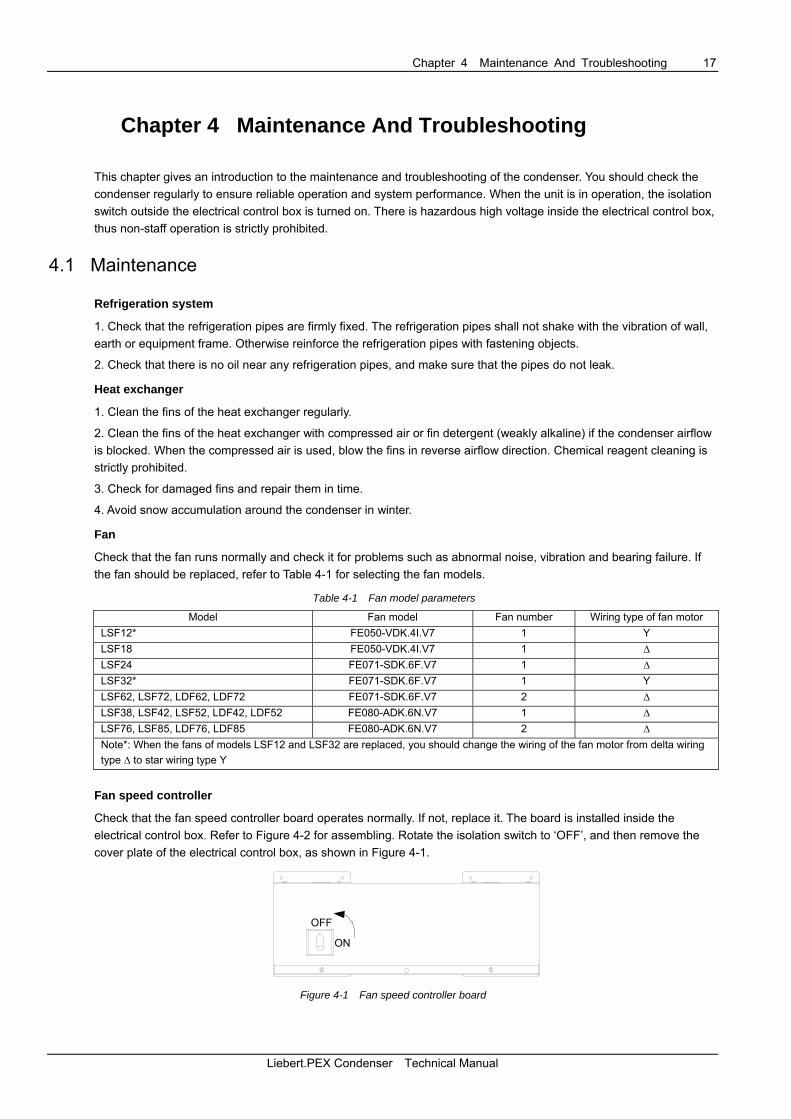
Check that the fan runs normally and check it for problems such as abnormal noise, vibration and bearing failure. If the fan should be replaced, refer to Table 4-1 for selecting the fan models.
Table 4-1 Fan model parameters
Model Fan model Fan number Wiring type of fan motor LSF12* FE050-VDK.4I.V7 1 Y LSF18 FE050-VDK.4I.V7 1 ∆ LSF24 FE071-SDK.6F.V7 1 ∆ LSF32* FE071-SDK.6F.V7 1 Y LSF62, LSF72, LDF62, LDF72 FE071-SDK.6F.V7 2 ∆ LSF38, LSF42, LSF52, LDF42, LDF52 FE080-ADK.6N.V7 1 ∆ LSF76, LSF85, LDF76, LDF85 FE080-ADK.6N.V7 2 ∆ Note*: When the fans of models LSF12 and LSF32 are replaced, you should change the wiring of the fan motor from delta wiring type ∆ to star wiring type Y
Fan speed controller
Check that the fan speed controller board operates normally. If not, replace it. The board is installed inside the electrical control box. Refer to Figure 4-2 for assembling. Rotate the isolation switch to ‘OFF’, and then remove the cover plate of the electrical control box, as shown in Figure 4-1.
ON
OFF
Figure 4-1 Fan speed controller board
Liebert.PEX Condenser Technical Manual

18 Chapter 4 Maintenance And Troubleshooting
Fan speed controller board
Heat sink
71
2
3
4 56
Figure 4-2 Removing the fan speed controller board
Note 1. � ~ � in Figure 4-2 are seven bolts (M4 × 10). The bolt � and bolt � are used to fix the heat sink, others are used to fix the fan speed controller board. 2. Except for the seven bolts in Figure 4-2, other bolts are prohibited to remove. 3. While installing the fan speed controller board, bolt � and bolt �, used to fix the heat sink, must be fastened firstly. The heat sink must cling to the back plate of the electrical control box. After installing the heat sink, use other five bolts to fix the fan speed controller board. Pressure sensor
If the standard configuration pressure sensor fails, follow the instructions below to select the type and install the sensor.
Selecting pressure sensor type
To ensure the measurement precision of the condensing pressure, the pressure sensor should be selected as follows:
1. The type of the pressure sensor should match the fan speed controller.
2. The configured pressure sensor type (see Figure 3-9) must be the same as the actual type.
3. The current type pressure sensor must meet 4mA ~ 20mA corresponding to 0 ~ 30bar; the voltage type pressure sensor must meet 0.5V ~ 4.5V corresponding to 0 ~ 34bar.
4. Except for the type configuration, all parameters of the pressure sensor should be amended by factory prior to use.
Installing pressure sensor
The condenser is configured with current type pressure sensor in factory. If the pressure sensor should be replaced, the current type pressure sensor is recommended. If the voltage pressure sensor has to be used because of special condition, refer to the following steps:
1. Remove the current type pressure sensors on J14 and J15 terminals (see Figure 3-2) and the jumper caps of the current type pressure sensors on J17 and J18 terminals (see Figure 3-2).
2. Connect the voltage type pressure sensor to J3 and J4 terminals (see Figure 3-2). For the type configuration of pressure sensor, refer to Configuration main menu interface in 3.4 Operation Description Of HMI.
Liebert.PEX Condenser Technical Manual
Chapter 4 Maintenance And Troubleshooting 19
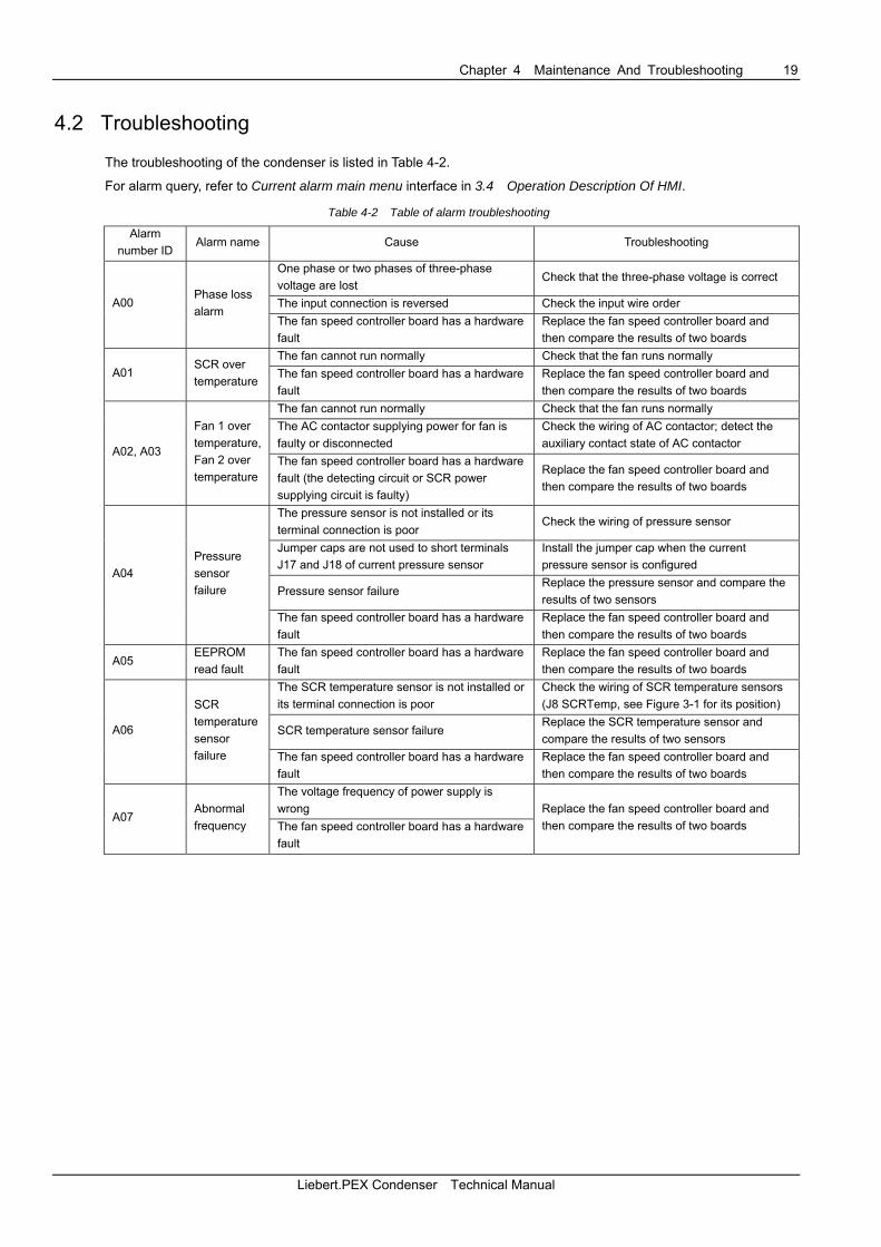
4.2 Troubleshooting
The troubleshooting of the condenser is listed in Table 4-2.
For alarm query, refer to Current alarm main menu interface in 3.4 Operation Description Of HMI.
Table 4-2 Table of alarm troubleshooting
Alarm number ID
Alarm name Cause Troubleshooting
One phase or two phases of three-phase voltage are lost
Check that the three-phase voltage is correct
The input connection is reversed Check the input wire order A00 Phase loss alarm
The fan speed controller board has a hardware fault
Replace the fan speed controller board and then compare the results of two boards
The fan cannot run normally Check that the fan runs normally A01
SCR over temperature The fan speed controller board has a hardware
fault Replace the fan speed controller board and then compare the results of two boards
The fan cannot run normally Check that the fan runs normally The AC contactor supplying power for fan is faulty or disconnected
Check the wiring of AC contactor; detect the auxiliary contact state of AC contactor
A02, A03
Fan 1 over temperature, Fan 2 over temperature
The fan speed controller board has a hardware fault (the detecting circuit or SCR power supplying circuit is faulty)
Replace the fan speed controller board and then compare the results of two boards
The pressure sensor is not installed or its terminal connection is poor
Check the wiring of pressure sensor
Jumper caps are not used to short terminals J17 and J18 of current pressure sensor
Install the jumper cap when the current pressure sensor is configured
Pressure sensor failure Replace the pressure sensor and compare the results of two sensors
A04 Pressure sensor failure
The fan speed controller board has a hardware fault
Replace the fan speed controller board and then compare the results of two boards
A05 EEPROM read fault
The fan speed controller board has a hardware fault
Replace the fan speed controller board and then compare the results of two boards
The SCR temperature sensor is not installed or its terminal connection is poor
Check the wiring of SCR temperature sensors (J8 SCRTemp, see Figure 3-1 for its position)
SCR temperature sensor failure Replace the SCR temperature sensor and compare the results of two sensors
A06
SCR temperature sensor failure The fan speed controller board has a hardware
fault Replace the fan speed controller board and then compare the results of two boards
The voltage frequency of power supply is wrong
A07 Abnormal frequency The fan speed controller board has a hardware
fault
Replace the fan speed controller board and then compare the results of two boards
Liebert.PEX Condenser Technical Manual

20 Appendix 1 Condenser Matching Table
Appendix 1 Condenser Matching Table
1. R22 Matching Table
See Table 1 for the matching relationships of single circuit condensers for PEX Small Frame.
Table 1 Matching table of single circuit condensers
Matching condensers at different temperatures Model of indoor unit
30°C 35°C 40°C P1010 LSF12 LSF12 LSF12 P1015 LSF18 LSF18 LSF18 P2020 LSF24 LSF24 LSF24 P2025 LSF32 LSF32 LSF32
See Table 2 for the matching relationships of single circuit condensers for PEX Large Frame.
Table 2 Matching table of single circuit condensers
Matching condensers at different temperatures Model of indoor unit
30°C 35°C 40°C P1020 LSF24 LSF24 LSF32 P1025 LSF32 LSF32 LSF32 P1030 LSF38 LSF38 LSF42 P1035 LSF42 LSF42 LSF52 P2035 LSF42 LSF42 LSF52 P2045 LSF52 LSF52 LSF62 P2055 LSF62 LSF62 LSF62 P2040 LSF24 × 2 LSF24 × 2 LSF32 × 2 P2050 LSF32 × 2 LSF32 × 2 LSF32 × 2 P2060 LSF38 × 2 LSF38 × 2 LSF42 × 2 P2070 LSF42 × 2 LSF42 × 2 LSF52 × 2 P3070 LSF42 × 2 LSF42 × 2 LSF52 × 2 P3080 LSF52 × 2 LSF52 × 2 LSF52 × 2 P3090 LSF52 × 2 LSF52 × 2 LSF62 × 2 P3100 LSF62 × 2 LSF62 × 2 LSF62 × 2
See Table 3 for the matching relationships of dual circuit condensers for PEX Large Frame.
Table 3 Matching table of dual circuit condensers
Matching condensers at different temperatures Model of indoor unit
30°C 35°C 40°C P2040 LDF42 LDF42 LDF52 P2050 LDF52 LDF52 LDF62 P2060 LDF62 LDF62 LDF72 P2070 LDF76 LDF76 LDF85 P3070 LDF76 LDF76 LDF85 P3080 - - - P3090 - - - P3100 - - -
Liebert.PEX Condenser Technical Manual
Appendix 1 Condenser Matching Table 21
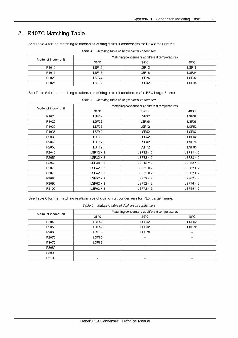
2. R407C Matching Table
See Table 4 for the matching relationships of single circuit condensers for PEX Small Frame.
Table 4 Matching table of single circuit condensers
Matching condensers at different temperatures Model of indoor unit
30°C 35°C 40°C P1010 LSF12 LSF12 LSF18 P1015 LSF18 LSF18 LSF24 P2020 LSF24 LSF24 LSF32 P2025 LSF32 LSF32 LSF38
See Table 5 for the matching relationships of single circuit condensers for PEX Large Frame.
Table 5 Matching table of single circuit condensers
Matching condensers at different temperatures Model of indoor unit
30°C 35°C 40°C P1020 LSF32 LSF32 LSF38 P1025 LSF32 LSF38 LSF38 P1030 LSF38 LSF42 LSF52 P1035 LSF42 LSF52 LSF62 P2035 LSF42 LSF52 LSF62 P2045 LSF62 LSF62 LSF76 P2055 LSF62 LSF72 LSF85 P2040 LSF32 × 2 LSF32 × 2 LSF38 × 2 P2050 LSF32 × 2 LSF38 × 2 LSF38 × 2 P2060 LSF38 × 2 LSF42 × 2 LSF52 × 2 P2070 LSF42 × 2 LSF52 × 2 LSF62 × 2 P3070 LSF42 × 2 LSF52 × 2 LSF62 × 2 P3080 LSF52 × 2 LSF52 × 2 LSF62 × 2 P3090 LSF62 × 2 LSF62 × 2 LSF76 × 2 P3100 LSF62 × 2 LSF72 × 2 LSF85 × 2
See Table 6 for the matching relationships of dual circuit condensers for PEX Large Frame.
Table 6 Matching table of dual circuit condensers
Matching condensers at different temperatures Model of indoor unit
35°C 35°C 40°C P2040 LDF52 LDF52 LDF62 P2050 LDF52 LDF62 LDF72 P2060 LDF76 LDF76 - P2070 LDF85 - - P3070 LDF85 P3080 - - - P3090 - - - P3100 - - -
Liebert.PEX Condenser Technical Manual
22 Appendix 2 Circuit Diagram
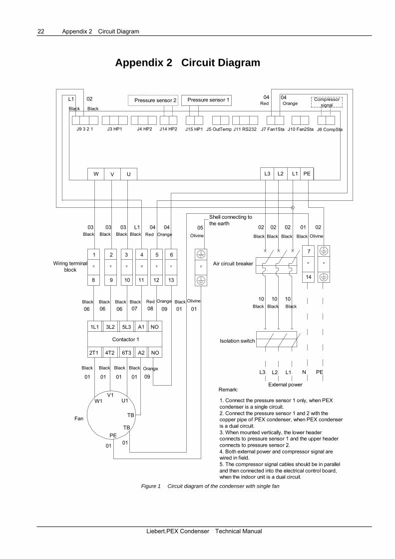
Appendix 2 Circuit Diagram
W UV
J11 RS232J5 OutTemp J10 Fan2StaJ7 Fan1Sta J6 CompSta
02
Remark:
Black
Contactor 1
Olivine
Wiring terminalblock
Olivine
Shell connecting tothe earth
Air circuit breaker
Olivine
External power
Pressure sensor 2 Pressure sensor 1 CompressorsignalRed
1. Connect the pressure sensor 1 only, when PEXcondenser is a single circuit.2. Connect the pressure sensor 1 and 2 with thecopper pipe of PEX condenser, when PEX condenseris a dual circuit.3. When mounted vertically, the lower headerconnects to pressure sensor 1 and the upper headerconnects to pressure sensor 2.4. Both external power and compressor signal arewired in field.5. The compressor signal cables should be in paralleland then connected into the electrical control board,when the indoor unit is a dual circuit.
Fan
Isolation switch
Black
Black
BlackBlack
Black Black
Black Black
BlackBlackBlack
Black Black BlackBlack Black
Black Black
Black
Red OrangeBlack Black
Orange
OrangeRed
Orange
L1
J9 3 2 1 J3 HP1 J4 HP2 J14 HP2 J15 HP1
0404
L3 L2 L1 PE
03 03 03 L1 04 04 05 02 02 02 01 02
1 2 3 4 5 6
8 9 10 11 12 13
7
14
10 10 10
01 01090807060606
1L1 3L2 A15L3 NO
NOA26T34T22T1
0901010101
W1V1
U1
TB
TBPE
01 01
L3 L2 L1 N PE
Figure 1 Circuit diagram of the condenser with single fan
Liebert.PEX Condenser Technical Manual

Appendix 2 Circuit Diagram 23
76
J3 HP1 J4 HP2 J14 HP2 J15 HP1 J5 OutTemp J11 RS232 J7 Fan1Sta J10 Fan2Sta J6 CompSta
Remark:
1. Connect the pressure sensor 1 only, when PEXcondenser is a single circuit.2. Connect the pressure sensor 1 and 2 with thecopper pipe of PEX condenser, when PEXcondenser is a dual circuit.3. When mounted vertically, the lower headerconnects to pressure sensor 1 and the upperheader connects to pressure sensor 2.4. Both external power and compressor signal arewired in field.5. The compressor signal cables should be inparallel and then connected into the electricalcontrol board, when the indoor unit is a dual circuit.
Air circuitbreaker
External power
Shell connectingto the earth OlivineBlack White Orange
Olivine
Black White Orange Olivine
Brown
OlivineBrown
Black Orange Black Orange
Contactor 1 Contactor 2
Fan1 (remote) Fan2(proximal)
Wiring terminalblock
CompressorWhite Brown Orange
Isolationswitch
Black Black Black Black Black Black
Black Black Black BlackBlack
Black Black Black BlackBlack Black
BlackBlack Black
03 Pressure sensor 2Black Black
L1
J9 3 2 1
Pressure sensor 1 06 10 11
W UV L3 L2 L1 PE
04 04 04 L1 06
1 2 3 4 5
10 11
12 13 14
07 07 07 08 09
15 16
05 03 03 03 03
8 9
17 18
10 10 1009 09 02 01 02 01
1L1 3L2 A15L3 NO 1L1 3L2 A15L3 NO
2T1 4T2 6T3 A2 NO 2T1 4T2 6T3 A2 NO
01 01 01 01 09 02 02 02 02 09
01 01 02 02
W1V1 U1
TBTB
PE
W1V1 U1
TBTB
PE
L3 L2 L1 N PE
signal
Figure 2 Circuit diagram of the condenser with double fans
Liebert.PEX Condenser Technical Manual
24 Appendix 3 Lifting Figure
Appendix 3 Lifting Figure
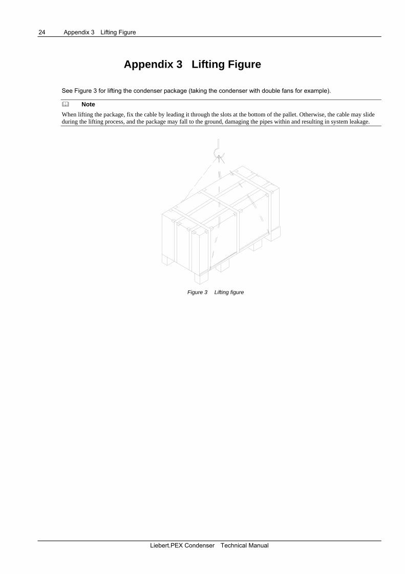
See Figure 3 for lifting the condenser package (taking the condenser with double fans for example).
Note When lifting the package, fix the cable by leading it through the slots at the bottom of the pallet. Otherwise, the cable may slide during the lifting process, and the package may fall to the ground, damaging the pipes within and resulting in system leakage.
Figure 3 Lifting figure
Liebert.PEX Condenser Technical Manual

Emerson Network Power Asia
Emerson Network Power.
EmersonNetworkPower.com
AP11ENT-PEXCondenserV1-TDM