Embed Size (px)
Citation preview
United Launch Alliance 58th International Astronautical Congress, 2007
- 1 -
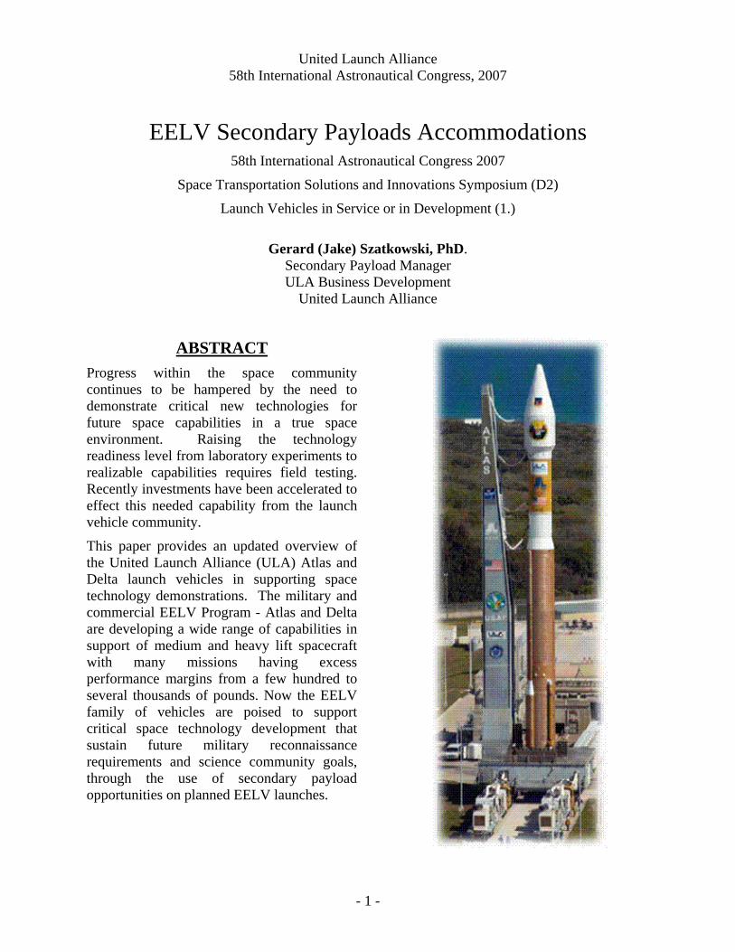
EELV Secondary Payloads Accommodations 58th International Astronautical Congress 2007
Space Transportation Solutions and Innovations Symposium (D2)
Launch Vehicles in Service or in Development (1.)
Gerard (Jake) Szatkowski, PhD.
Secondary Payload Manager ULA Business Development
United Launch Alliance
ABSTRACT Progress within the space community continues to be hampered by the need to demonstrate critical new technologies for future space capabilities in a true space environment. Raising the technology readiness level from laboratory experiments to realizable capabilities requires field testing. Recently investments have been accelerated to effect this needed capability from the launch vehicle community.
This paper provides an updated overview of the United Launch Alliance (ULA) Atlas and Delta launch vehicles in supporting space technology demonstrations. The military and commercial EELV Program - Atlas and Delta are developing a wide range of capabilities in support of medium and heavy lift spacecraft with many missions having excess performance margins from a few hundred to several thousands of pounds. Now the EELV family of vehicles are poised to support critical space technology development that sustain future military reconnaissance requirements and science community goals, through the use of secondary payload opportunities on planned EELV launches.
United Launch Alliance 58th International Astronautical Congress, 2007
- 2 -
1 Secondary Payload Benefits In recent years the efforts applied to space technologies have exploded. Many universities and government labs have become involved. The rapid development of secondary payloads (SPs), leading to integration and test, only serves to improve the technology readiness level (TRL) for these emerging systems. Further, the Operationally Responsive Space (ORS) technology initiatives need to demonstrate these technologies and techniques to have them available for new space systems.
The bottleneck in this process is that present launch vehicles (LVs) have not had the focus on providing near-term inexpensive rides into space so that these small satellites can be demonstrated within a reasonable academic or R&D study period. Waiting years to field a demonstration renders moot any technology benefit.
From a self-serving point of view, the benefit of secondary payloads to the LV is not as a source of revenue. The true benefit is to improve the TRL of new techniques so that the risk to the larger programs employing that new technology can be reduced so that they in turn can be fully deployed in their planned constellation and on schedule. A full deployment vs a reduced or delayed deployment means more launches to the LV community.
On the larger scale, the benefit to society of supporting secondaries is that the student, engineers, and scientists that work on their development, can remain active in their field of expertise and later are part of the new work force that serves the next generation. Without that opportunity the labor force misses out on the experience and bears the risk of leaving the space industry.
2. Philosophical Approach for Secondary Payloads The reality for LVs is that their primary focus remains the Primary customer mission. What this means to the Secondary community is that the Primary retains the schedule, maintains the manifest, the day-of-launch authority and approval of flying SP on their mission. Until the Primary community gets comfortable with flying Secondaries, the Primary will complete their mission first before any Secondaries get deployed. In time, this kind of restriction hopefully will relax. Further, the Primary integration, launch, and mission can not be impacted by the SPs. That means we will have to provide mass simulators for any SP in the event that the SP is not ready to be integrated at the time for encapsulation.
With that said, now the question is how to make the SP and carrier a more robust design so that we maintain the maximum degree of flexibility in the launch. First the carrier needs to dynamically isolate the SP from the Primary to the maximum extent possible. Simplifying the dynamic loads introduced by the SPs to the system make the accommodation much easier. Also the margin on a given mission get released in stages as the development process matures. By allowing SPs to be added when that margin does become available is a goal. This degree of flexibility may not be permissible at present, but we can work toward that end. Today the designation of a mission to support SPs must come at the initiation of the launch campaign to avoid any re-work actives. One way to help in this effort is to develop enveloping specifications to reduce the variety of mission integration tasks and a more robust Interface Control Document (ICD) to provide a better user guide to the SP community.
United Launch Alliance 58th International Astronautical Congress, 2007
- 3 -
Another area that would help the SPs become better accepted by the Primaries is to reduce integration risks. Part of ULA's LV philosophy has been to do "test-like-you-fly" (TLYF). What this means is that SPs need to take the time to verify integration activities prior to getting to the launch site. Things like mechanical match/mate, electrical I/Fs, telemetry interfaces, software loads, required checkout testing, and commands from the LV, etc. To do this ULA is developing a facility to allow SPs to resolve these interfaces in a lab or clean-room environment. Schedule is another risk, particularly at the launch site. By having the ability to do things in parallel independent of the Primary mission integration frees schedule. Things that permit late integration, right up to final encapsulation, are helpful.
3. Issues for SPs So what are the issues that still face SPs acceptance by the Primary customer community? Well the Primary is footing the bill for the mission and is reluctant to share any risk with lower priority payloads. There is little incentive for the Primary. If SPs are to be allowed a ride, the Primary authorizing agency must decide if this is a policy they want to embrace. Directive for such a policy must be made at the highest levels for it to change things down at the mission level.
Similarly, the LVs have a risk-adverse mind-set. In the commercial sector, and SPs would be risk assumed by the LV. Again, until SPs become more common, LVs have little incentive to fly SPs. From our EELV perspective, the driving function to accept SPs is if the government customers adopt this acceptance. The LVs recognize the need and if the government customers push the non-recurring engineering, then the launch vehicles will go along. In this environment however, the LV is likely to be very conservative with the required analyses and associated costs.
The lessons learned from the STP-1 Mission need to be digested. There were a variety of problems that occurred during integration. First was just from the complexity of integrating such a variety of spacecraft (S/C). Adding to the problem was the late arrival of some of the experiments. Much misunderstanding among the SP providers about the environments caused qualification concerns. Extra work was done to decide if load-simulators would be required and if there were further control/dynamic concerns. Late in the integration testing electromagnetic interference (EMI) erupted regarding the motorized release mechanism. Changes were ultimately made that re-designed the separation device and this further delayed the final integration testing. All in all the entire integration process was very expensive and time-consuming, with a great deal of re-work effort that need to be avoided in the future.
Other issues concern qualifying and accepting the SPs by the launch provider. A defined method for qualification and certification of the SPs needs to be developed. Some testing can only be done by the LV shop but much can be done by independent laboratories well suited to that kind of work. The LV would like to have the SPs arrive for integration with their paperwork all in order and with range release certificates in hand.
4. SPs Interface Definitions As mentioned earlier, an ICD that contains enough material to be used as a user manual for developers of SP would be a good start in reducing costs and integration time-lines.
The following is what ULA envisions is need to be in such an ICD: • Enveloping guides for mass, volume, etc. • Separation clearances, spin rates, tip-off angle rates, etc.
United Launch Alliance 58th International Astronautical Congress, 2007
- 4 -
• Allowable shock environments, qualified separation devices • RF environments and interface limitations • Power availability in-flight, trickle-charge power • Telemetry interleave availability • Environmental control and standards, certification requirements • Events and timing requirements • Range certification requirements
ULA is pursuing the development of some of these elements under R&D activities.
A link to the Atlas and Delta MISSION PLANNERS GUIDES is below: http://www.ulalaunch.com/index_products_services.html
5. SPs Systems Integration As discussed earlier, an integration plan for SPs must be independent of the Primary. The desire of the SP community is to decide as late as possible to designate a particular mission as a SP mission. To begin the integration process with the LV as late as possible and to seamlessly move on to encapsulation and launch.
The reality is that, for the initial launch capability, the designation of a mission for an SP must be made at the beginning of a new launch campaign. To satisfy the TLYF requirement, the LV would want the SP up to 1 year ahead of launch to perform certification testing in our avionics SIL. Motorized device separation systems would be particularly suspect until proven that they pose no EMI issues.
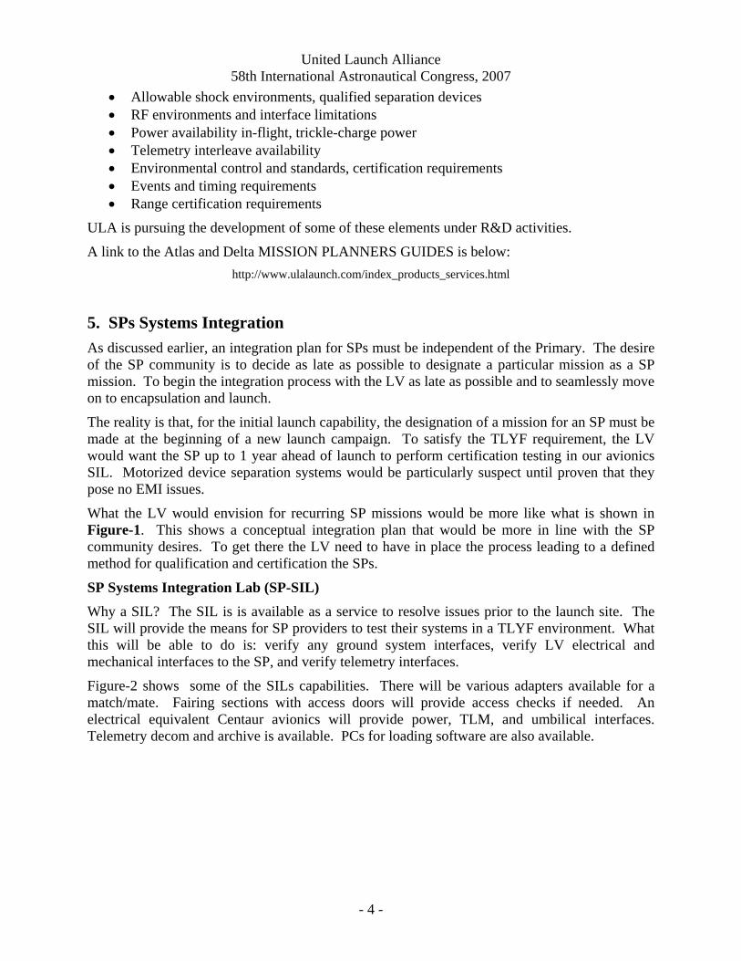
What the LV would envision for recurring SP missions would be more like what is shown in Figure-1. This shows a conceptual integration plan that would be more in line with the SP community desires. To get there the LV need to have in place the process leading to a defined method for qualification and certification the SPs.
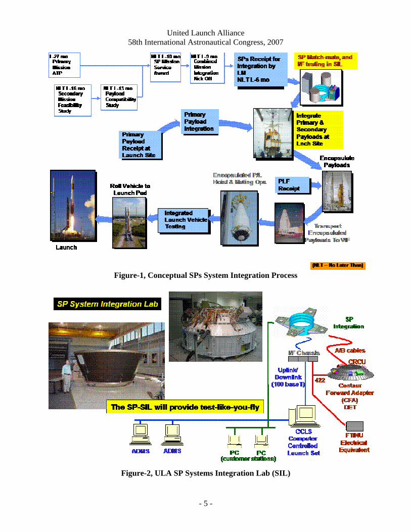
SP Systems Integration Lab (SP-SIL) Why a SIL? The SIL is is available as a service to resolve issues prior to the launch site. The SIL will provide the means for SP providers to test their systems in a TLYF environment. What this will be able to do is: verify any ground system interfaces, verify LV electrical and mechanical interfaces to the SP, and verify telemetry interfaces.
Figure-2 shows some of the SILs capabilities. There will be various adapters available for a match/mate. Fairing sections with access doors will provide access checks if needed. An electrical equivalent Centaur avionics will provide power, TLM, and umbilical interfaces. Telemetry decom and archive is available. PCs for loading software are also available.
United Launch Alliance 58th International Astronautical Congress, 2007
- 5 -
Figure-1, Conceptual SPs System Integration Process
Figure-2, ULA SP Systems Integration Lab (SIL)
United Launch Alliance 58th International Astronautical Congress, 2007
- 6 -
6. SPs Mission Concept: Delta II and IV Rideshare Capabilities: ULA has been working with the Air Force Space and Missile Systems Command (SMC) to investigate SPs on EELV missions that have adequate margins. The end goal is to regularly fly SPs with both government and commercial payloads that have excess payload margin.
The EELV program has been developing, both under contract and IR&D, multiple approaches to support SPs. These SP's options are at varying levels of design maturity ranging from conceptual to flight qualified hardware.
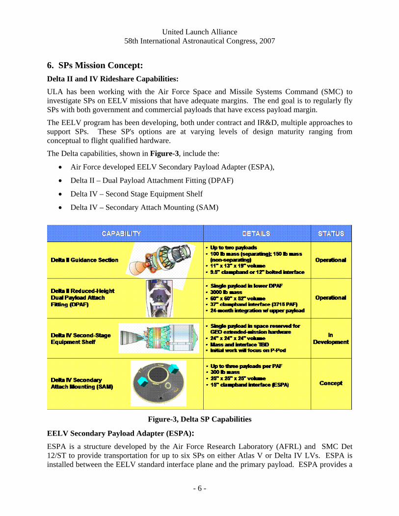
The Delta capabilities, shown in Figure-3, include the:
• Air Force developed EELV Secondary Payload Adapter (ESPA),
• Delta II – Dual Payload Attachment Fitting (DPAF)
• Delta IV – Second Stage Equipment Shelf
• Delta IV – Secondary Attach Mounting (SAM)
Figure-3, Delta SP Capabilities
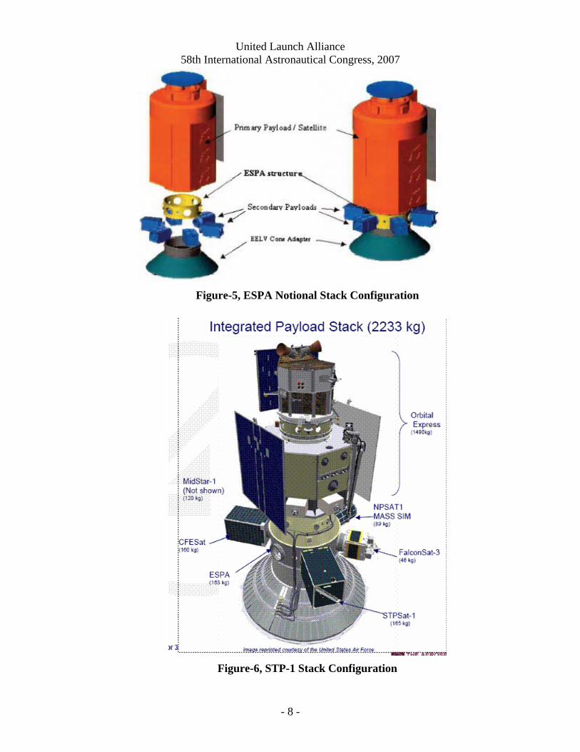
EELV Secondary Payload Adapter (ESPA): ESPA is a structure developed by the Air Force Research Laboratory (AFRL) and SMC Det 12/ST to provide transportation for up to six SPs on either Atlas V or Delta IV LVs. ESPA is installed between the EELV standard interface plane and the primary payload. ESPA provides a
United Launch Alliance 58th International Astronautical Congress, 2007
- 7 -
structure to support all required thermal, mechanical and electrical interfaces to the SPs. SPs are deployed post Primary separation. ESPA SPs are limited to 400 lbm each with dimensions of 24 in. X 28 in. X 38 in. approximately.
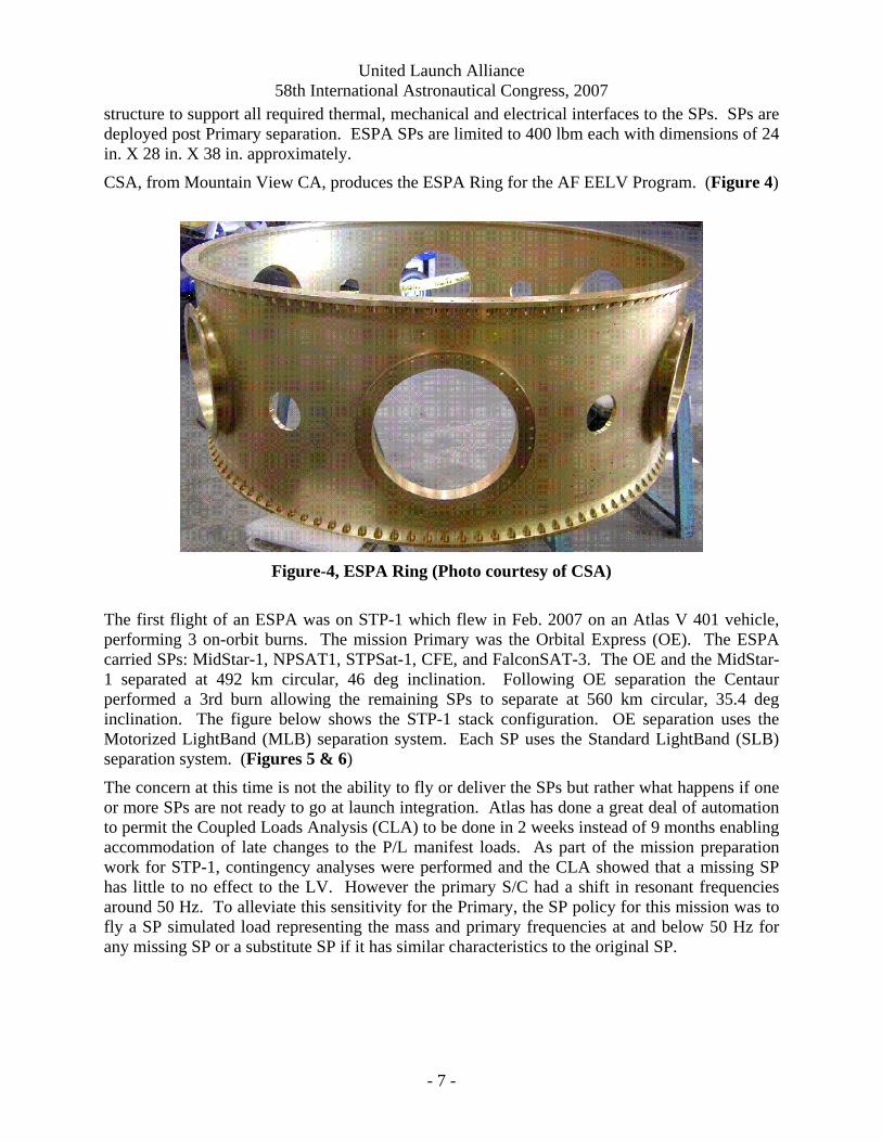
CSA, from Mountain View CA, produces the ESPA Ring for the AF EELV Program. (Figure 4)
Figure-4, ESPA Ring (Photo courtesy of CSA)
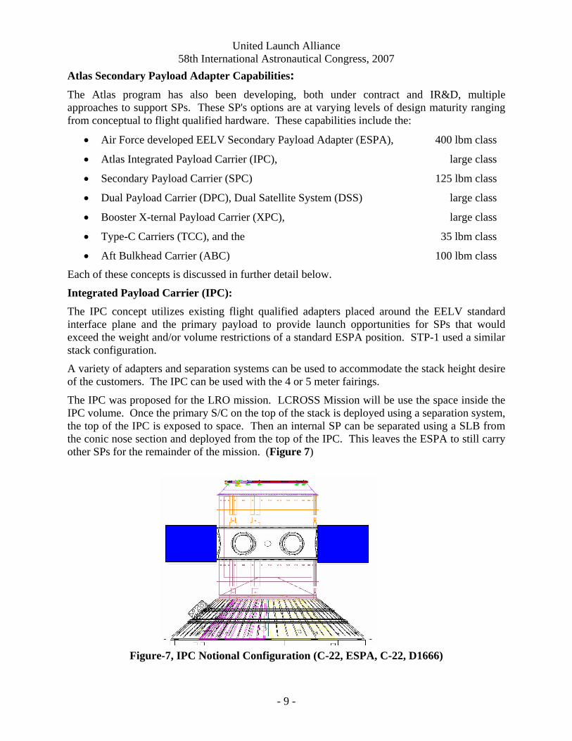
The first flight of an ESPA was on STP-1 which flew in Feb. 2007 on an Atlas V 401 vehicle, performing 3 on-orbit burns. The mission Primary was the Orbital Express (OE). The ESPA carried SPs: MidStar-1, NPSAT1, STPSat-1, CFE, and FalconSAT-3. The OE and the MidStar-1 separated at 492 km circular, 46 deg inclination. Following OE separation the Centaur performed a 3rd burn allowing the remaining SPs to separate at 560 km circular, 35.4 deg inclination. The figure below shows the STP-1 stack configuration. OE separation uses the Motorized LightBand (MLB) separation system. Each SP uses the Standard LightBand (SLB) separation system. (Figures 5 & 6)
The concern at this time is not the ability to fly or deliver the SPs but rather what happens if one or more SPs are not ready to go at launch integration. Atlas has done a great deal of automation to permit the Coupled Loads Analysis (CLA) to be done in 2 weeks instead of 9 months enabling accommodation of late changes to the P/L manifest loads. As part of the mission preparation work for STP-1, contingency analyses were performed and the CLA showed that a missing SP has little to no effect to the LV. However the primary S/C had a shift in resonant frequencies around 50 Hz. To alleviate this sensitivity for the Primary, the SP policy for this mission was to fly a SP simulated load representing the mass and primary frequencies at and below 50 Hz for any missing SP or a substitute SP if it has similar characteristics to the original SP.
United Launch Alliance 58th International Astronautical Congress, 2007
- 8 -
Figure-5, ESPA Notional Stack Configuration
Figure-6, STP-1 Stack Configuration
United Launch Alliance 58th International Astronautical Congress, 2007
- 9 -
Atlas Secondary Payload Adapter Capabilities: The Atlas program has also been developing, both under contract and IR&D, multiple approaches to support SPs. These SP's options are at varying levels of design maturity ranging from conceptual to flight qualified hardware. These capabilities include the:
• Air Force developed EELV Secondary Payload Adapter (ESPA), 400 lbm class
• Atlas Integrated Payload Carrier (IPC), large class
• Secondary Payload Carrier (SPC) 125 lbm class
• Dual Payload Carrier (DPC), Dual Satellite System (DSS) large class
• Booster X-ternal Payload Carrier (XPC), large class
• Type-C Carriers (TCC), and the 35 lbm class
• Aft Bulkhead Carrier (ABC) 100 lbm class
Each of these concepts is discussed in further detail below.
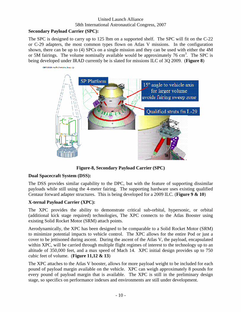
Integrated Payload Carrier (IPC): The IPC concept utilizes existing flight qualified adapters placed around the EELV standard interface plane and the primary payload to provide launch opportunities for SPs that would exceed the weight and/or volume restrictions of a standard ESPA position. STP-1 used a similar stack configuration.
A variety of adapters and separation systems can be used to accommodate the stack height desire of the customers. The IPC can be used with the 4 or 5 meter fairings.
The IPC was proposed for the LRO mission. LCROSS Mission will be use the space inside the IPC volume. Once the primary S/C on the top of the stack is deployed using a separation system, the top of the IPC is exposed to space. Then an internal SP can be separated using a SLB from the conic nose section and deployed from the top of the IPC. This leaves the ESPA to still carry other SPs for the remainder of the mission. (Figure 7)
Figure-7, IPC Notional Configuration (C-22, ESPA, C-22, D1666)
United Launch Alliance 58th International Astronautical Congress, 2007
- 10 -
Secondary Payload Carrier (SPC): The SPC is designed to carry up to 125 lbm on a supported shelf. The SPC will fit on the C-22 or C-29 adapters, the most common types flown on Atlas V missions. In the configuration shown, there can be up to (4) SPCs on a single mission and they can be used with either the 4M or 5M fairings. The volume nominally available would be approximately 76 cm3. The SPC is being developed under IRAD currently be is slated for missions ILC of 3Q 2009. (Figure 8)
Figure-8, Secondary Payload Carrier (SPC)
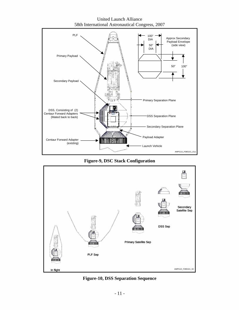
Dual Spacecraft System (DSS): The DSS provides similar capability to the DPC, but with the feature of supporting dissimilar payloads while still using the 4-meter fairing. The supporting hardware uses existing qualified Centaur forward adapter structures. This is being developed for a 2009 ILC. (Figure 9 & 10)
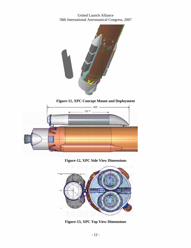
X-ternal Payload Carrier (XPC): The XPC provides the ability to demonstrate critical sub-orbital, hypersonic, or orbital (additional kick stage required) technologies, The XPC connects to the Atlas Booster using existing Solid Rocket Motor (SRM) attach points.
Aerodynamically, the XPC has been designed to be comparable to a Solid Rocket Motor (SRM) to minimize potential impacts to vehicle control. The XPC allows for the entire Pod or just a cover to be jettisoned during ascent. During the ascent of the Atlas V, the payload, encapsulated within XPC, will be carried through multiple flight regimes of interest to the technology up to an altitude of 350,000 feet, and a max speed of Mach 14. XPC initial design provides up to 750 cubic feet of volume. (Figure 11,12 & 13)
The XPC attaches to the Atlas V booster, allows for more payload weight to be included for each pound of payload margin available on the vehicle. XPC can weigh approximately 8 pounds for every pound of payload margin that is available. The XPC is still in the preliminary design stage, so specifics on performance indexes and environments are still under development.
United Launch Alliance 58th International Astronautical Congress, 2007
- 11 -
Primary Payload
Secondary Payload
PLF
Centaur Forward Adapter(existing)
DSS, Consisting of (2)Centaur Forward Adapters
(Mated back to back)
AMPG10_F080101_01a
DSS Separation Plane
Primary Separation Plane
Secondary Separation Plane
Payload Adapter
Launch Vehicle
Approx Secondary Payload Envelope
(side view)50”DIA
50” 100”
100”DIA
Figure-9, DSC Stack Configuration
AMPG10_F080101_02
PLF SepPLF Sep
Primary Satellite SepPrimary Satellite Sep
AMPG10_XXXX
DSS Sep
AMPG10_XXXX
DSS Sep
SecondarySatellite SepSecondary
Satellite Sep
In flightIn flight Figure-10, DSS Separation Sequence
United Launch Alliance 58th International Astronautical Congress, 2007
- 12 -
Figure-11, XPC Concept Mount and Deployment
Figure-12, XPC Side View Dimensions
Figure-13, XPC Top View Dimensions

United Launch Alliance 58th International Astronautical Congress, 2007
- 13 -
Type-C Carrier (TCC): The TCC is a reference to the Atlas payload interface C-Adapters. These ring-sections are produced in various heights and used as spacers to adjust the positioning of the primary payload with the fairing. Each flight carries at least one C-Adapter section which doubles as a strongback during hoist operations. These structures are monolithic aluminum with identical ring fittings on either end. The sides of the C-Adapter and the internal volume are available for SPs. Since every Atlas mission already uses a C adapter the TCC provides an extremely low cost, low impact method to fly SPs on most Atlas missions. Two potential uses of the TCC are to carry pPodsTM or RocketPodsTM by Ecliptic. (Figure 14)
Figure-14, Type-C Carrier (TCC) for pPods
pPod – The pPodTM is a carrier mounting and deployment system for CubeSatsTM produced by the Aerospace Deptartment of the California Polytechnic Institute, San Luis Obisbo, CA. The pPodTM can carry up to three CubeSatsTM units in the same pod. A safe-arm / activation mechanism is enabled by the Centaur avionics to power a thermal release mechanism to open the trap-door retaining the CubeSats. A spring system then deploys them out away from the TCC. The pPodTM measures about 10 cm x 10 cm x 40 cm.
CubeSat –The CubeSat is a deployable nano-satellite that is self contained, powered by solar cells on the cube surface, and can transmit data on commercial short-wave band signals. The CubeSatTM requires no support from the launch vehicle either from the ground or in flight. As a result, the CubeSatTM can be integrated long before the actual launch.
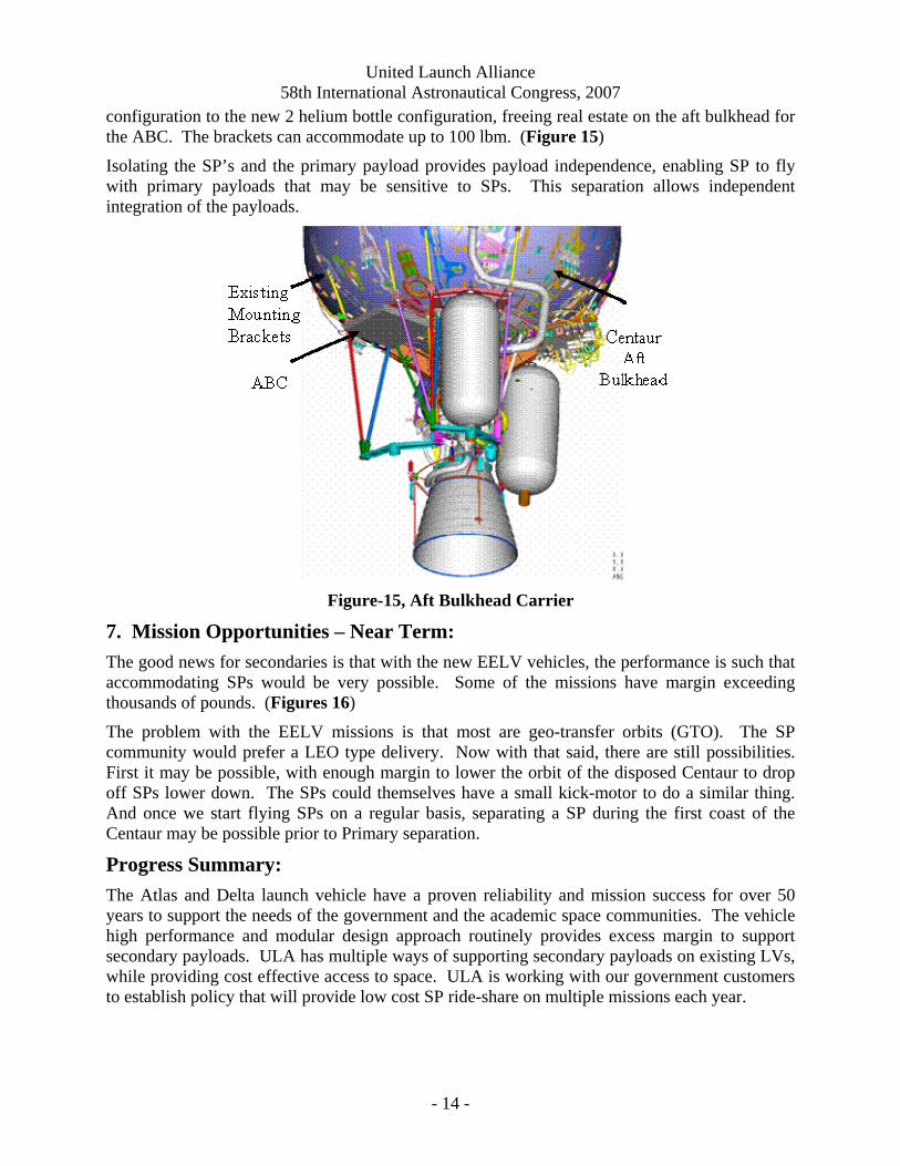
Aft Bulkhead Carrier (ABC): The ABC provides a SP capability completely independent from the primary payload. The ABC consists of a shelf that is mounted to the Centaur LO2 tank aft bulkhead. The mounting takes advantage of existing unused brackets and mounting design similar to the current helium bottle mounting struts. The ABC is enabled by the Centaur transition from a 3 helium bottle
United Launch Alliance 58th International Astronautical Congress, 2007
- 14 -
configuration to the new 2 helium bottle configuration, freeing real estate on the aft bulkhead for the ABC. The brackets can accommodate up to 100 lbm. (Figure 15)
Isolating the SP’s and the primary payload provides payload independence, enabling SP to fly with primary payloads that may be sensitive to SPs. This separation allows independent integration of the payloads.
Figure-15, Aft Bulkhead Carrier
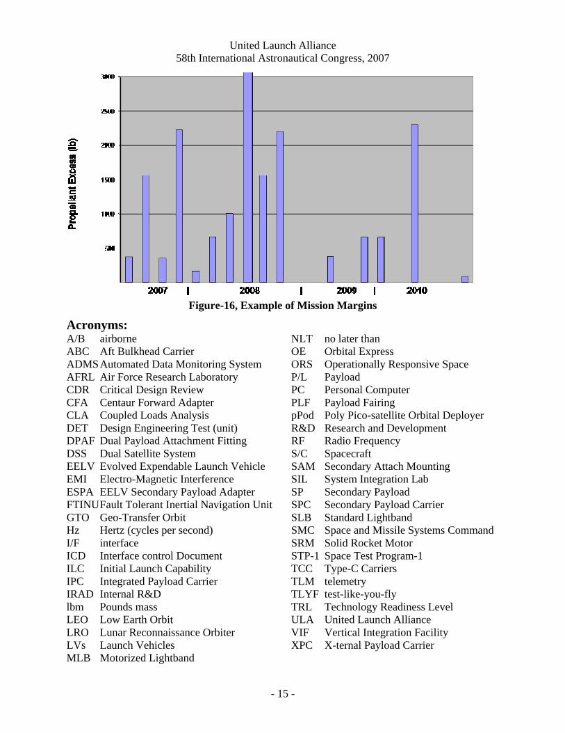
7. Mission Opportunities – Near Term: The good news for secondaries is that with the new EELV vehicles, the performance is such that accommodating SPs would be very possible. Some of the missions have margin exceeding thousands of pounds. (Figures 16)
The problem with the EELV missions is that most are geo-transfer orbits (GTO). The SP community would prefer a LEO type delivery. Now with that said, there are still possibilities. First it may be possible, with enough margin to lower the orbit of the disposed Centaur to drop off SPs lower down. The SPs could themselves have a small kick-motor to do a similar thing. And once we start flying SPs on a regular basis, separating a SP during the first coast of the Centaur may be possible prior to Primary separation.
Progress Summary: The Atlas and Delta launch vehicle have a proven reliability and mission success for over 50 years to support the needs of the government and the academic space communities. The vehicle high performance and modular design approach routinely provides excess margin to support secondary payloads. ULA has multiple ways of supporting secondary payloads on existing LVs, while providing cost effective access to space. ULA is working with our government customers to establish policy that will provide low cost SP ride-share on multiple missions each year.
United Launch Alliance 58th International Astronautical Congress, 2007
- 15 -
Figure-16, Example of Mission Margins
Acronyms: A/B airborne ABC Aft Bulkhead Carrier ADMS Automated Data Monitoring System AFRL Air Force Research Laboratory CDR Critical Design Review CFA Centaur Forward Adapter CLA Coupled Loads Analysis DET Design Engineering Test (unit) DPAF Dual Payload Attachment Fitting DSS Dual Satellite System EELV Evolved Expendable Launch Vehicle EMI Electro-Magnetic Interference ESPA EELV Secondary Payload Adapter FTINU Fault Tolerant Inertial Navigation Unit GTO Geo-Transfer Orbit Hz Hertz (cycles per second) I/F interface ICD Interface control Document ILC Initial Launch Capability IPC Integrated Payload Carrier IRAD Internal R&D lbm Pounds mass LEO Low Earth Orbit LRO Lunar Reconnaissance Orbiter LVs Launch Vehicles MLB Motorized Lightband
NLT no later than OE Orbital Express ORS Operationally Responsive Space P/L Payload PC Personal Computer PLF Payload Fairing pPod Poly Pico-satellite Orbital Deployer R&D Research and Development RF Radio Frequency S/C Spacecraft SAM Secondary Attach Mounting SIL System Integration Lab SP Secondary Payload SPC Secondary Payload Carrier SLB Standard Lightband SMC Space and Missile Systems Command SRM Solid Rocket Motor STP-1 Space Test Program-1 TCC Type-C Carriers TLM telemetry TLYF test-like-you-fly TRL Technology Readiness Level ULA United Launch Alliance VIF Vertical Integration Facility XPC X-ternal Payload Carrier