Embed Size (px)
Citation preview
1
Fall 2011 EECS150 Lecture 8 Page 1
EECS150 - Digital DesignLecture 8 –MIPS Processor Review
September 20, 2011
Elad AlonElectrical Engineering and Computer Sciences
University of California, Berkeley
http://www-inst.eecs.berkeley.edu/~cs150
Fall 2011 EECS150 Lecture 8 Page 2
Announcements• Homework #3 due Thurs.
• Homework #4 out this Thurs.– Due next Thurs.
2
Fall 2011 EECS150 Lecture 8 Page 3
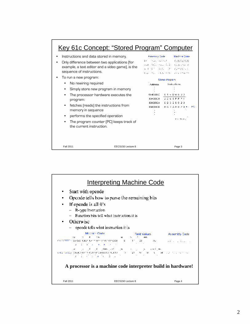
Key 61c Concept: “Stored Program” Computer• Instructions and data stored in memory.
• Only difference between two applications (for example, a text editor and a video game), is the sequence of instructions.
• To run a new program:
• No rewiring required
• Simply store new program in memory
• The processor hardware executes the program:
• fetches (reads) the instructions from memory in sequence
• performs the specified operation
• The program counter (PC) keeps track of the current instruction.
Fall 2011 EECS150 Lecture 8 Page 4
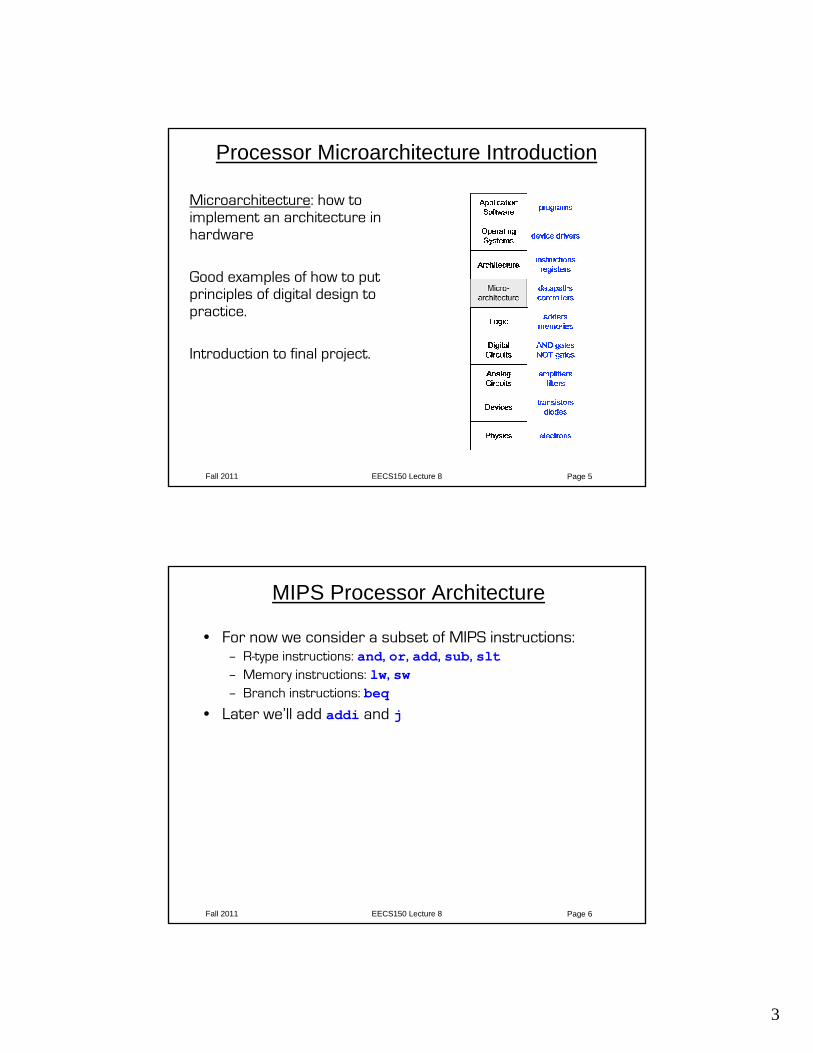
Interpreting Machine Code
A processor is a machine code interpreter build in hardware!
3
Fall 2011 EECS150 Lecture 8 Page 5
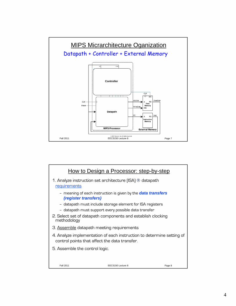
Processor Microarchitecture Introduction
Microarchitecture: how to implement an architecture in hardware
Good examples of how to put principles of digital design to practice.
Introduction to final project.
Fall 2011 EECS150 Lecture 8 Page 6
MIPS Processor Architecture
• For now we consider a subset of MIPS instructions:– R-type instructions: and, or, add, sub, slt– Memory instructions: lw, sw– Branch instructions: beq
• Later we’ll add addi and j
4
Fall 2011 EECS150 Lecture 8 Page 7
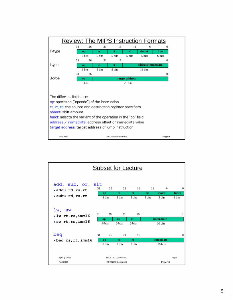
MIPS Micrarchitecture OganizationDatapath + Controller + External Memory
Controller
Fall 2011 EECS150 Lecture 8 Page 8
How to Design a Processor: step-by-step1. Analyze instruction set architecture (ISA) ® datapath
requirements
– meaning of each instruction is given by the data transfers (register transfers)
– datapath must include storage element for ISA registers– datapath must support every possible data transfer
2. Select set of datapath components and establish clocking methodology
3. Assemble datapath meeting requirements
4. Analyze implementation of each instruction to determine setting of control points that affect the data transfer.
5. Assemble the control logic.
5
Fall 2011 EECS150 Lecture 8 Page 9
Review: The MIPS Instruction FormatsR-type
I-type
J-type
The different fields are:op: operation (“opcode”) of the instructionrs, rt, rd: the source and destination register specifiersshamt: shift amountfunct: selects the variant of the operation in the “op” fieldaddress / immediate: address offset or immediate valuetarget address: target address of jump instruction
op target address02631
6 bits 26 bits
op rs rt rd shamt funct061116212631
6 bits 6 bits5 bits5 bits5 bits5 bits
op rs rt address/immediate016212631
6 bits 16 bits5 bits5 bits
Fall 2011 EECS150 Lecture 8 Page 10
Spring 2011 EECS150 - Lec09-cpu Page
Subset for Lecture
add, sub, or, slt•addu rd,rs,rt•subu rd,rs,rt
lw, sw•lw rt,rs,imm16•sw rt,rs,imm16
beq•beq rs,rt,imm16
op rs rt rd shamt funct061116212631
6 bits 6 bits5 bits5 bits5 bits5 bits
op rs rt immediate016212631
6 bits 16 bits5 bits5 bits
op rs rt immediate016212631
6 bits 16 bits5 bits5 bits
6
Fall 2011 EECS150 Lecture 8 Page 11
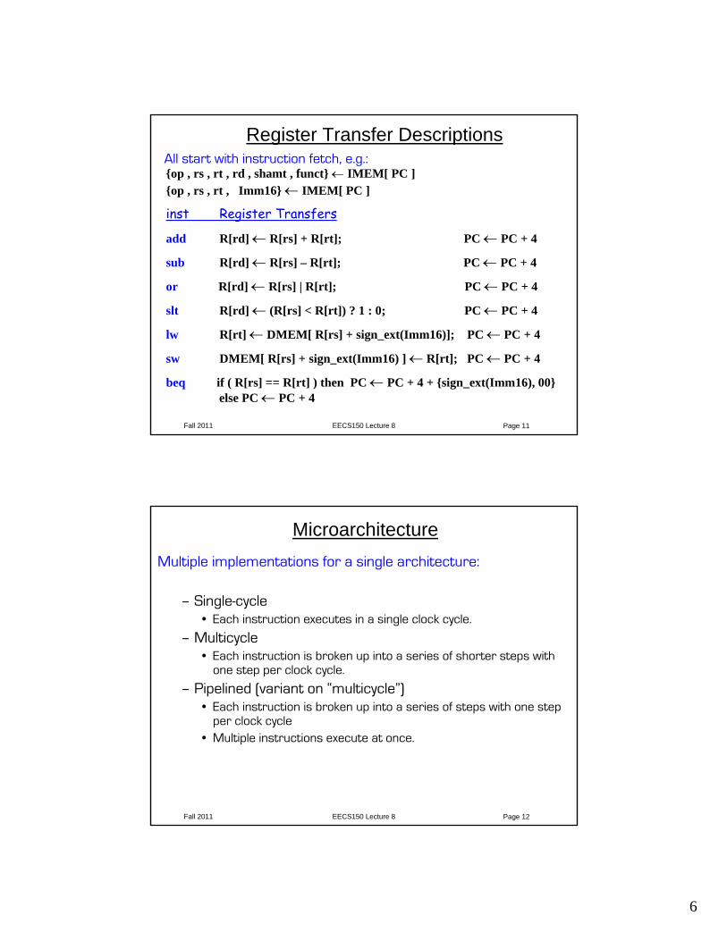
Register Transfer DescriptionsAll start with instruction fetch, e.g.:{op , rs , rt , rd , shamt , funct} ← IMEM[ PC ] {op , rs , rt , Imm16} ← IMEM[ PC ]
inst Register Transfers
add R[rd] ← R[rs] + R[rt]; PC ← PC + 4
sub R[rd] ← R[rs] – R[rt]; PC ← PC + 4
or R[rd] ← R[rs] | R[rt]; PC ← PC + 4
slt R[rd] ← (R[rs] < R[rt]) ? 1 : 0; PC ← PC + 4
lw R[rt] ← DMEM[ R[rs] + sign_ext(Imm16)]; PC ← PC + 4
sw DMEM[ R[rs] + sign_ext(Imm16) ] ← R[rt]; PC ← PC + 4
beq if ( R[rs] == R[rt] ) then PC ← PC + 4 + {sign_ext(Imm16), 00}else PC ← PC + 4
Fall 2011 EECS150 Lecture 8 Page 12
MicroarchitectureMultiple implementations for a single architecture:
– Single-cycle• Each instruction executes in a single clock cycle.
– Multicycle• Each instruction is broken up into a series of shorter steps with
one step per clock cycle.
– Pipelined (variant on “multicycle”)• Each instruction is broken up into a series of steps with one step
per clock cycle• Multiple instructions execute at once.
7
Fall 2011 EECS150 Lecture 8 Page 13
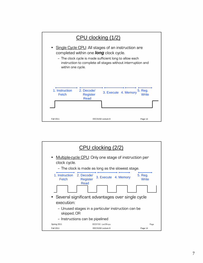
CPU clocking (1/2)
• Single Cycle CPU: All stages of an instruction are completed within one long clock cycle. – The clock cycle is made sufficient long to allow each
instruction to complete all stages without interruption and within one cycle.
1. InstructionFetch
2. Decode/RegisterRead
3. Execute 4. Memory 5. Reg.Write
Fall 2011 EECS150 Lecture 8 Page 14
Spring 2011 EECS150 - Lec09-cpu Page
CPU clocking (2/2)
• Multiple-cycle CPU: Only one stage of instruction per clock cycle. – The clock is made as long as the slowest stage.
• Several significant advantages over single cycle execution:– Unused stages in a particular instruction can be
skipped, OR
– Instructions can be pipelined
1. InstructionFetch
2. Decode/RegisterRead
3. Execute 4. Memory 5. Reg.Write
8
Fall 2011 EECS150 Lecture 8 Page 15
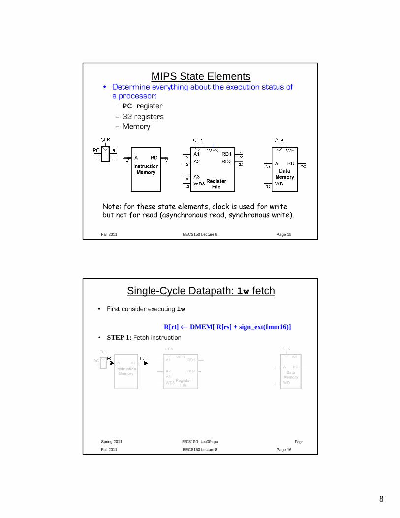
MIPS State Elements• Determine everything about the execution status of
a processor:– PC register– 32 registers– Memory
Note: for these state elements, clock is used for write but not for read (asynchronous read, synchronous write).
Fall 2011 EECS150 Lecture 8 Page 16
Spring 2011 EECS150 - Lec09-cpu Page
Single-Cycle Datapath: lw fetch• First consider executing lw
• STEP 1: Fetch instruction
R[rt] ← DMEM[ R[rs] + sign_ext(Imm16)]
9
Fall 2011 EECS150 Lecture 8 Page 17
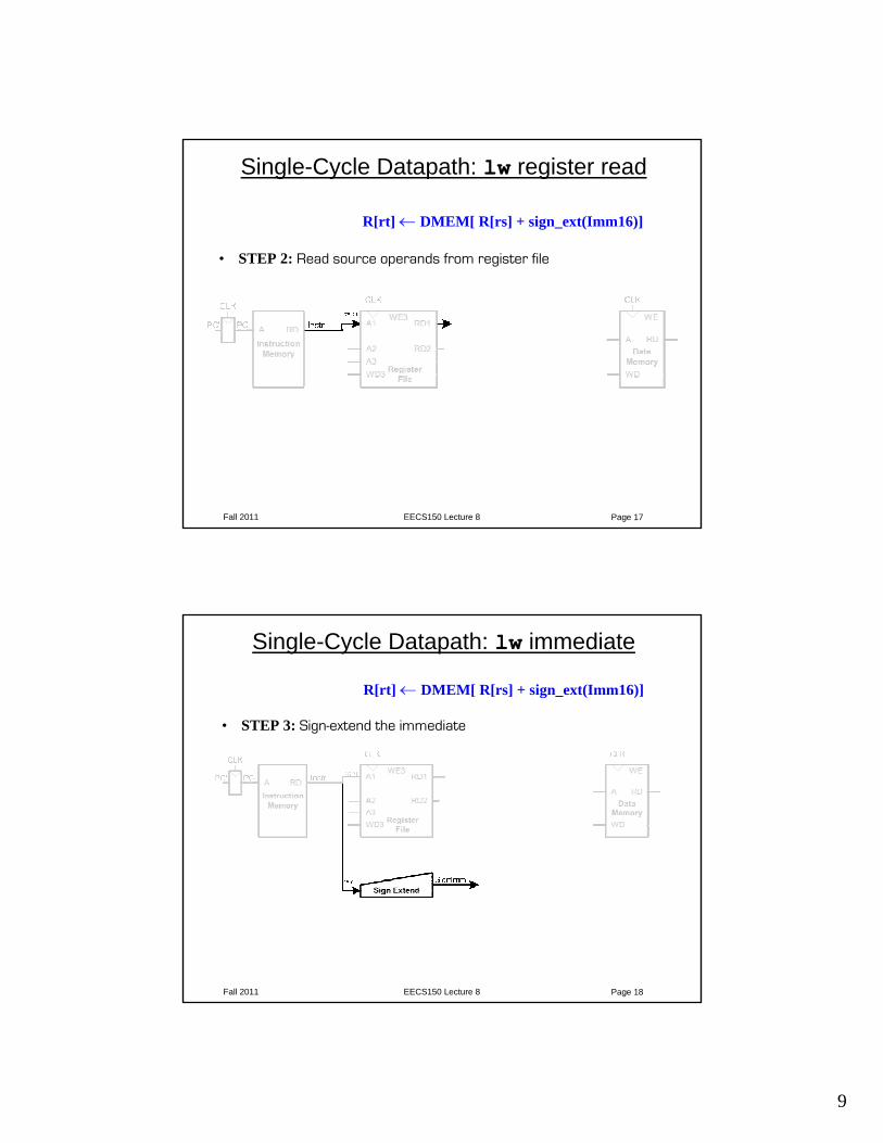
Single-Cycle Datapath: lw register read
• STEP 2: Read source operands from register file
R[rt] ← DMEM[ R[rs] + sign_ext(Imm16)]
Fall 2011 EECS150 Lecture 8 Page 18
Single-Cycle Datapath: lw immediate
• STEP 3: Sign-extend the immediate
R[rt] ← DMEM[ R[rs] + sign_ext(Imm16)]
10
Fall 2011 EECS150 Lecture 8 Page 19
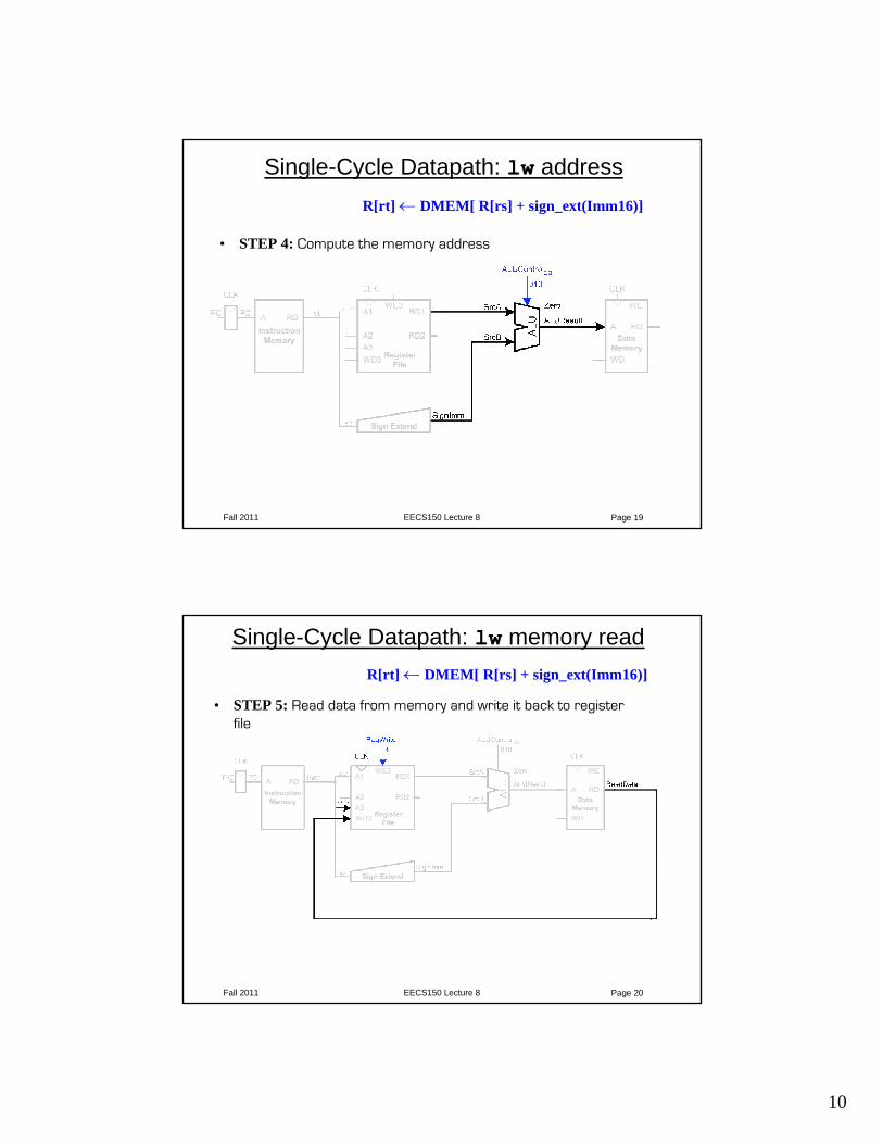
Single-Cycle Datapath: lw address
• STEP 4: Compute the memory address
R[rt] ← DMEM[ R[rs] + sign_ext(Imm16)]
Fall 2011 EECS150 Lecture 8 Page 20
Single-Cycle Datapath: lw memory read
• STEP 5: Read data from memory and write it back to register file
R[rt] ← DMEM[ R[rs] + sign_ext(Imm16)]
11
Fall 2011 EECS150 Lecture 8 Page 21
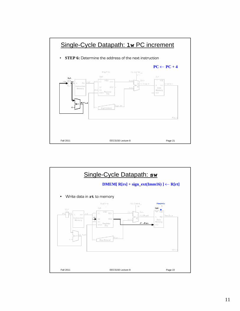
Single-Cycle Datapath: lw PC increment
• STEP 6: Determine the address of the next instruction
PC ← PC + 4
Fall 2011 EECS150 Lecture 8 Page 22
Single-Cycle Datapath: sw
• Write data in rt to memory
DMEM[ R[rs] + sign_ext(Imm16) ] ← R[rt]
12
Fall 2011 EECS150 Lecture 8 Page 23
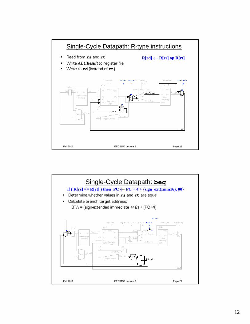
Single-Cycle Datapath: R-type instructions• Read from rs and rt• Write ALUResult to register file• Write to rd (instead of rt)
R[rd] ← R[rs] op R[rt]
Fall 2011 EECS150 Lecture 8 Page 24
Single-Cycle Datapath: beq
• Determine whether values in rs and rt are equal
• Calculate branch target address: BTA = (sign-extended immediate << 2) + (PC+4)
if ( R[rs] == R[rt] ) then PC ← PC + 4 + {sign_ext(Imm16), 00}
13
Fall 2011 EECS150 Lecture 8 Page 25
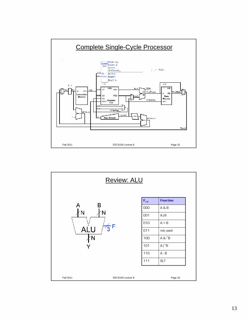
Complete Single-Cycle Processor
Fall 2011 EECS150 Lecture 8 Page 26
Review: ALU
F2:0 Function
000 A & B
001 A | B
010 A + B
011 not used
100 A & ~B
101 A | ~B
110 A - B
111 SLT
14
Fall 2011 EECS150 Lecture 8 Page 27
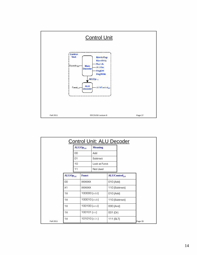
Control Unit
Fall 2011 EECS150 Lecture 8 Page 28
Control Unit: ALU DecoderALUOp1:0 Meaning
00 Add
01 Subtract
10 Look at Funct
11 Not Used
ALUOp1:0 Funct ALUControl2:0
00 XXXXXX 010 (Add)
X1 XXXXXX 110 (Subtract)
1X 100000 (add) 010 (Add)
1X 100010 (sub) 110 (Subtract)
1X 100100 (and) 000 (And)
1X 100101 (or) 001 (Or)
1X 101010 (slt) 111 (SLT)
15
Fall 2011 EECS150 Lecture 8 Page 29
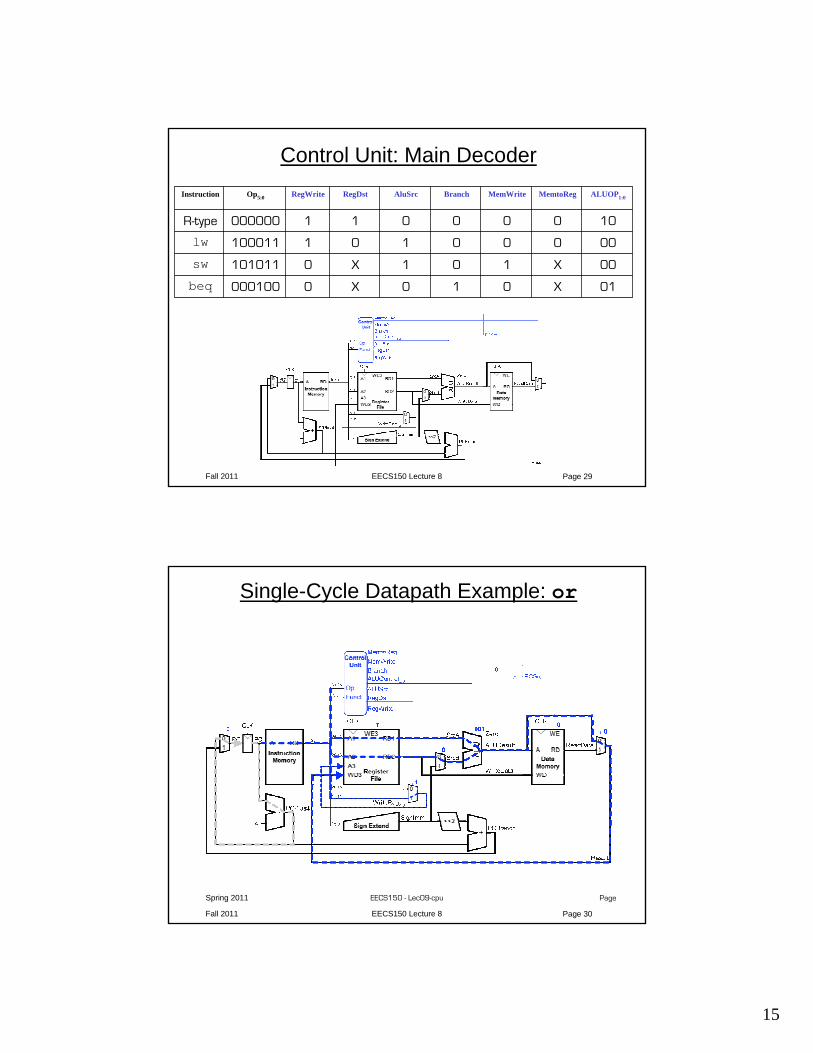
Control Unit: Main DecoderInstruction Op5:0 RegWrite RegDst AluSrc Branch MemWrite MemtoReg ALUOP1:0
R-type 000000 1 1 0 0 0 0 10
lw 100011 1 0 1 0 0 0 00
sw 101011 0 X 1 0 1 X 00
beq 000100 0 X 0 1 0 X 01
Fall 2011 EECS150 Lecture 8 Page 30
Spring 2011 EECS150 - Lec09-cpu Page
Single-Cycle Datapath Example: or
16
Fall 2011 EECS150 Lecture 8 Page 31
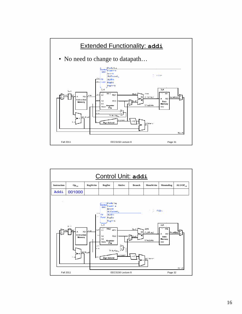
Extended Functionality: addi
• No need to change to datapath…
Fall 2011 EECS150 Lecture 8 Page 32
Control Unit: addiInstruction Op5:0 RegWrite RegDst AluSrc Branch MemWrite MemtoReg ALUOP1:0
Addi 001000
17
Fall 2011 EECS150 Lecture 8 Page 33
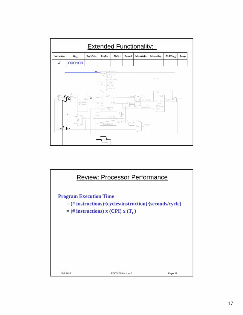
Extended Functionality: jInstruction Op5:0 RegWrite RegDst AluSrc Branch MemWrite MemtoReg ALUOp1:0 Jump
J 000100
Fall 2011 EECS150 Lecture 8 Page 34
Review: Processor Performance
Program Execution Time = (# instructions)·(cycles/instruction)·(seconds/cycle)= (# instructions) x (CPI) x (TC)
18
Fall 2011 EECS150 Lecture 8 Page 35
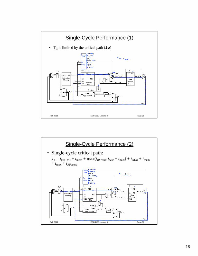
Single-Cycle Performance (1)
• TC is limited by the critical path (lw)
Fall 2011 EECS150 Lecture 8 Page 36
Single-Cycle Performance (2)• Single-cycle critical path:
Tc = tpcq_PC + tmem + max(tRFread, tsext + tmux) + tALU + tmem+ tmux + tRFsetup
19
Fall 2011 EECS150 Lecture 8 Page 37
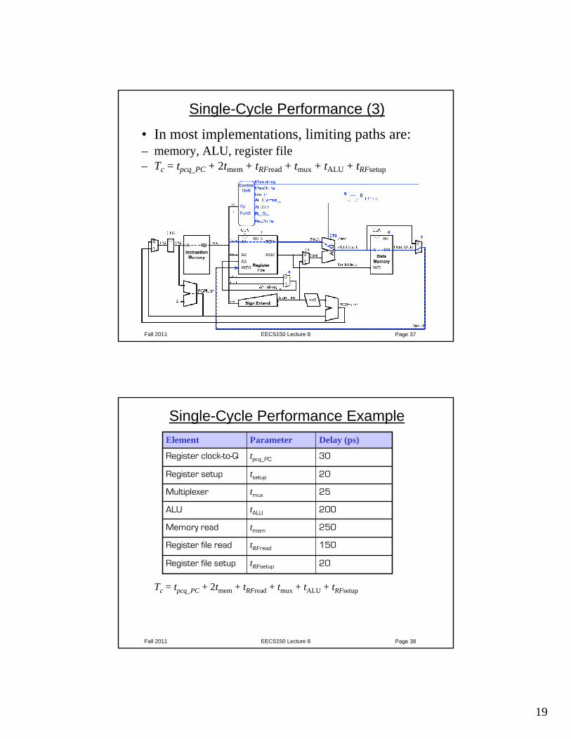
Single-Cycle Performance (3)
• In most implementations, limiting paths are: – memory, ALU, register file – Tc = tpcq_PC + 2tmem + tRFread + tmux + tALU + tRFsetup
Fall 2011 EECS150 Lecture 8 Page 38
Single-Cycle Performance Example
Tc = tpcq_PC + 2tmem + tRFread + tmux + tALU + tRFsetup
Element Parameter Delay (ps)
Register clock-to-Q tpcq_PC 30
Register setup tsetup 20
Multiplexer tmux 25
ALU tALU 200
Memory read tmem 250
Register file read tRFread 150
Register file setup tRFsetup 20
20
Fall 2011 EECS150 Lecture 8 Page 39
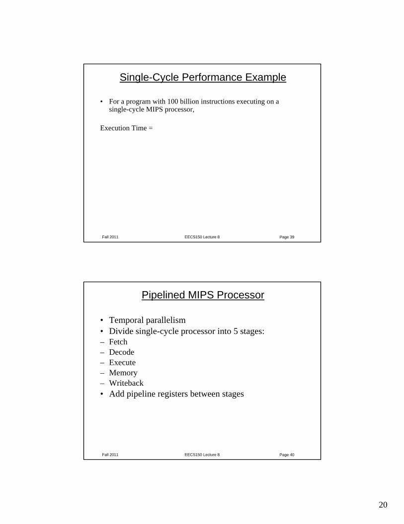
Single-Cycle Performance Example
• For a program with 100 billion instructions executing on a single-cycle MIPS processor,
Execution Time =
Fall 2011 EECS150 Lecture 8 Page 40
Pipelined MIPS Processor
• Temporal parallelism• Divide single-cycle processor into 5 stages:– Fetch– Decode– Execute– Memory– Writeback• Add pipeline registers between stages
21
Fall 2011 EECS150 Lecture 8 Page 41
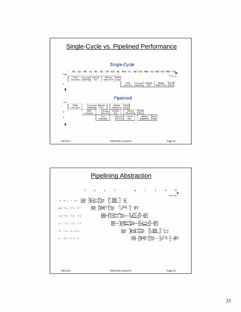
Single-Cycle vs. Pipelined Performance
Fall 2011 EECS150 Lecture 8 Page 42
Pipelining Abstraction
22
Fall 2011 EECS150 Lecture 8 Page 43
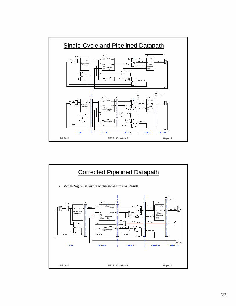
Single-Cycle and Pipelined Datapath
Fall 2011 EECS150 Lecture 8 Page 44
Corrected Pipelined Datapath
• WriteReg must arrive at the same time as Result
23
Fall 2011 EECS150 Lecture 8 Page 45
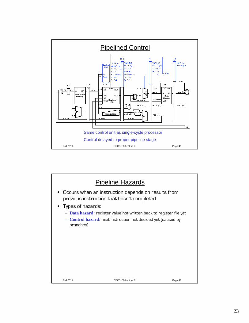
Pipelined Control
Same control unit as single-cycle processor
Control delayed to proper pipeline stage
Fall 2011 EECS150 Lecture 8 Page 46
Pipeline Hazards• Occurs when an instruction depends on results from
previous instruction that hasn’t completed.
• Types of hazards:– Data hazard: register value not written back to register file yet
– Control hazard: next instruction not decided yet (caused by branches)