Embed Size (px)
Citation preview

EECS 42, Spring 2005 Week 3a 1
Announcements
New topics: Mesh (loop) method of circuit analysis Superposition method of circuit analysis Equivalent circuit idea (Thevenin, Norton) Maximum power transfer from a circuit to a load
To stop blowing fuses in the lab, note how the breadboards are wired …

EECS 42, Spring 2005 Week 3a 2
Top view of board

EECS 42, Spring 2005 Week 3a 3
Bottom view of board – note which way the wires go
EECS 42, Spring 2005 Week 3a 4
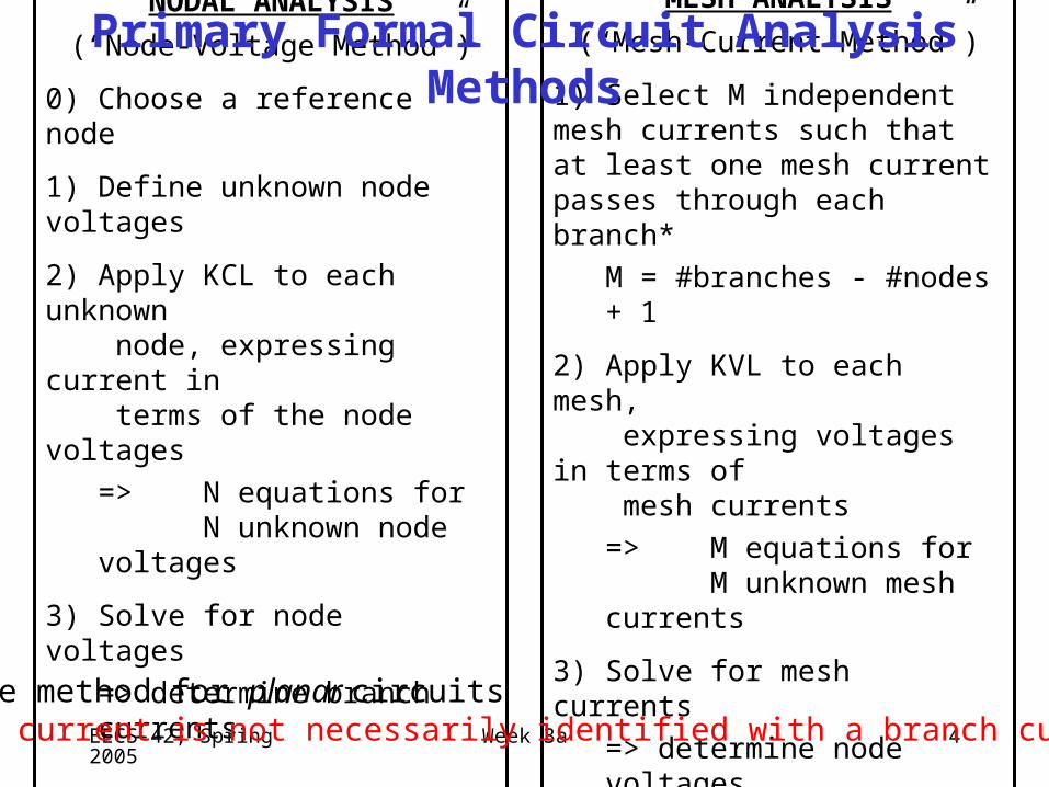
NODAL ANALYSIS
(“Node-Voltage Method”)
0) Choose a reference node
1) Define unknown node voltages
2) Apply KCL to each unknown node, expressing current in terms of the node voltages
=> N equations forN unknown node
voltages
3) Solve for node voltages
=> determine branch currents
MESH ANALYSIS
(“Mesh-Current Method”)
1) Select M independent mesh currents such that at least one mesh current passes through each branch*
M = #branches - #nodes + 1
2) Apply KVL to each mesh, expressing voltages in terms of mesh currents
=> M equations forM unknown mesh
currents
3) Solve for mesh currents
=> determine node voltages
Primary Formal Circuit Analysis Methods
*Simple method for planar circuitsA mesh current is not necessarily identified with a branch current.
EECS 42, Spring 2005 Week 3a 5
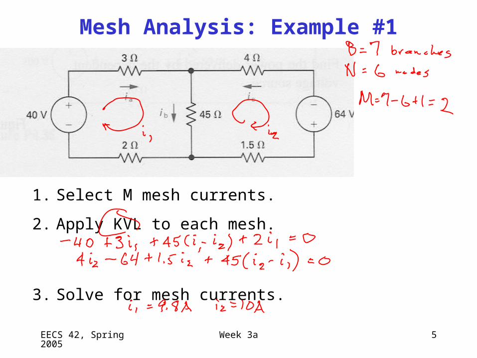
1. Select M mesh currents.
2. Apply KVL to each mesh.
3. Solve for mesh currents.
Mesh Analysis: Example #1
EECS 42, Spring 2005 Week 3a 6
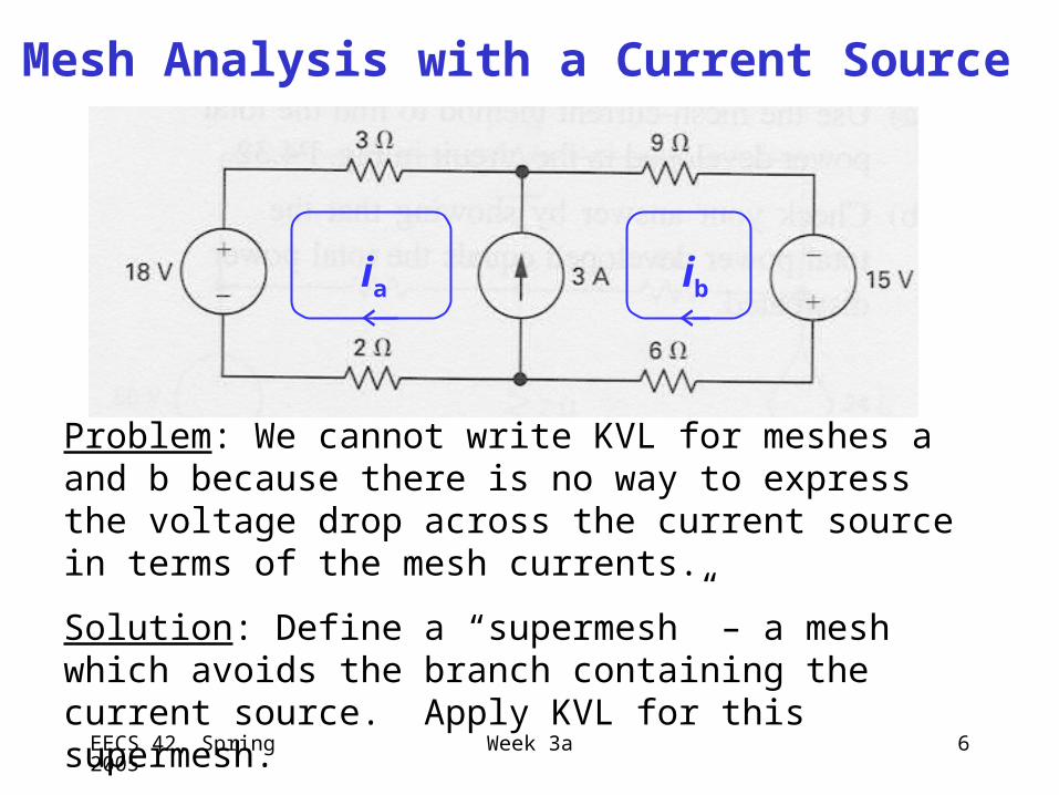
Problem: We cannot write KVL for meshes a and b because there is no way to express the voltage drop across the current source in terms of the mesh currents.
Solution: Define a “supermesh” – a mesh which avoids the branch containing the current source. Apply KVL for this supermesh.
Mesh Analysis with a Current Source
ia ib
EECS 42, Spring 2005 Week 3a 7
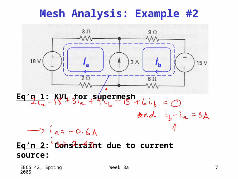
Eq’n 1: KVL for supermesh
Eq’n 2: Constraint due to current source:
Mesh Analysis: Example #2
ia ib
EECS 42, Spring 2005 Week 3a 8
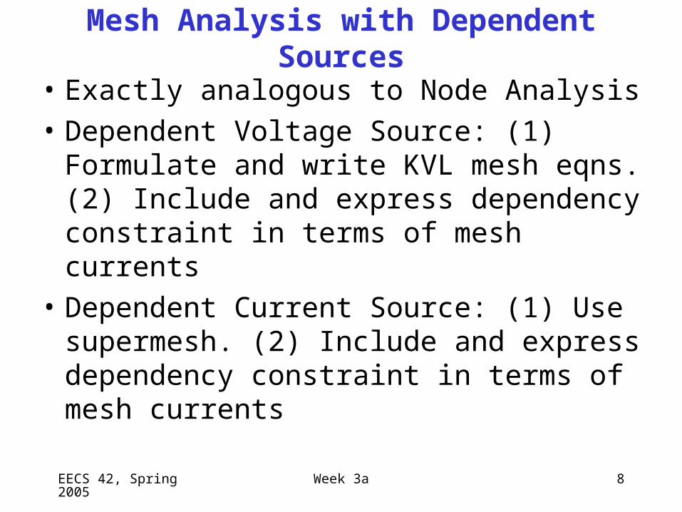
Mesh Analysis with Dependent Sources
• Exactly analogous to Node Analysis
• Dependent Voltage Source: (1) Formulate and write KVL mesh eqns. (2) Include and express dependency constraint in terms of mesh currents
• Dependent Current Source: (1) Use supermesh. (2) Include and express dependency constraint in terms of mesh currents
EECS 42, Spring 2005 Week 3a 9
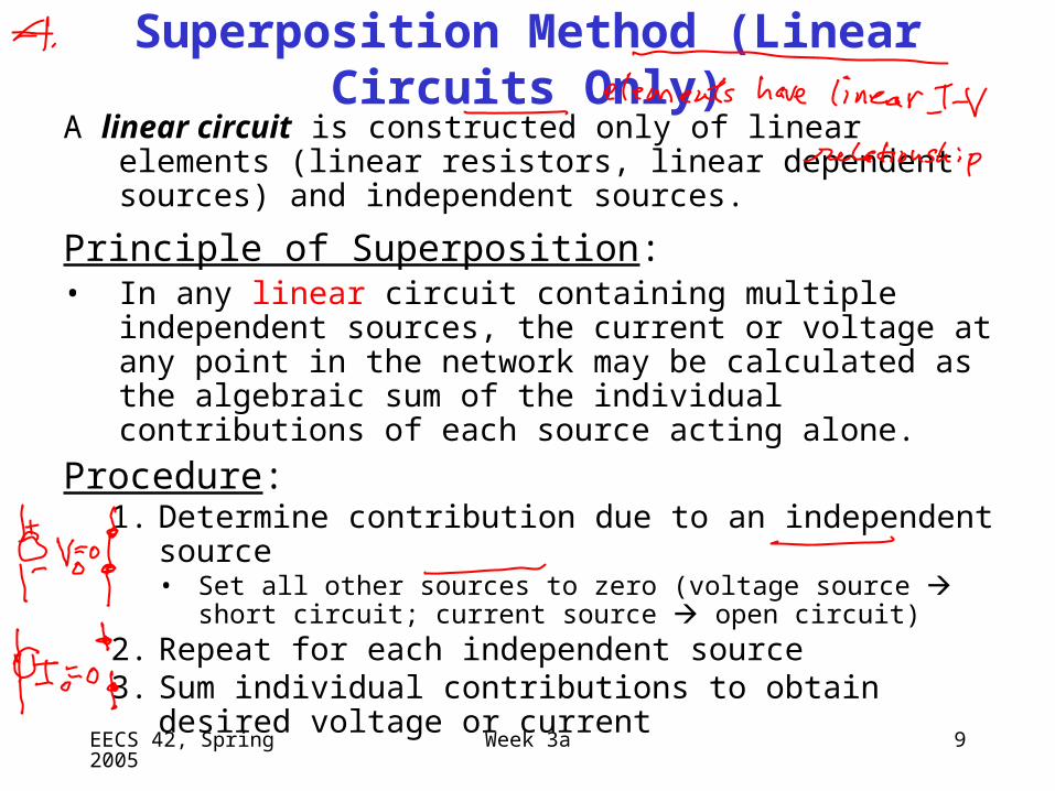
Superposition Method (Linear Circuits Only)
A linear circuit is constructed only of linear elements (linear resistors, linear dependent sources) and independent sources.
Principle of Superposition:• In any linear circuit containing multiple independent sources,
the current or voltage at any point in the network may be calculated as the algebraic sum of the individual contributions of each source acting alone.
Procedure:1. Determine contribution due to an independent source
• Set all other sources to zero (voltage source short circuit; current source open circuit)
2. Repeat for each independent source3. Sum individual contributions to obtain desired voltage or
current
EECS 42, Spring 2005 Week 3a 10
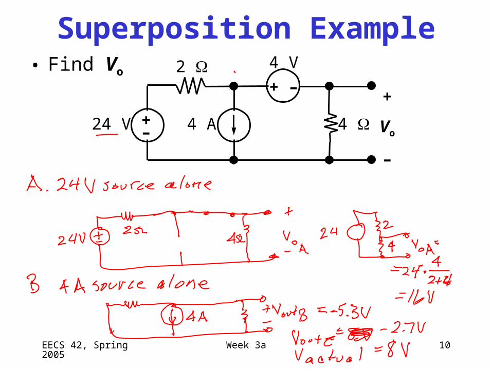
Superposition Example• Find Vo
–+
24 V
2
4 4 A
4 V
+ –+
Vo
–

EECS 42, Spring 2005 Week 3a 11
EECS 42, Spring 2005 Week 3a 12
Lecture 6, Slide 1EECS40, Spring 2004 Prof. Sanders
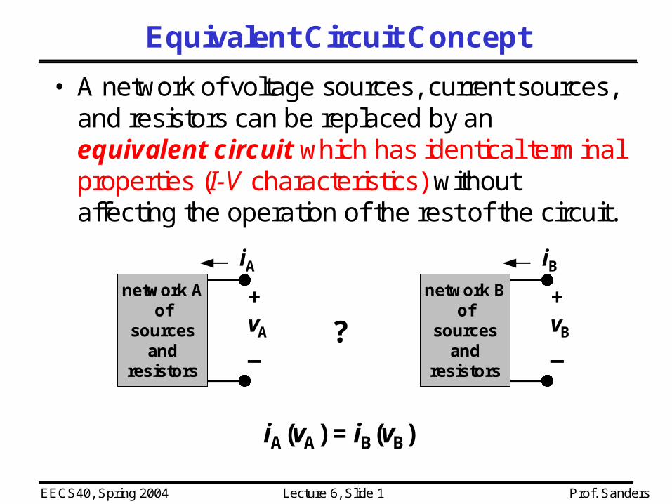
Equivalent Circuit Concept
• A network of voltage sources, current sources, and resistors can be replaced by an equivalent circuit which has identical terminal properties (I-V characteristics) without affecting the operation of the rest of the circuit.
+vA
_
network Aof
sourcesand
resistors
iA
?+vB
_
network Bof
sourcesand
resistors
iB
iA(vA) = iB(vB)

EECS 42, Spring 2005 Week 3a 13
• Voltage sources in series can be replaced by an equivalent voltage source:
• Current sources in parallel can be replaced by an equivalent current source:
Source Combinations
i1 i2 ≡ i1+i2
–+
–+
v1
v2
≡ –+
v1+v2
EECS 42, Spring 2005 Week 3a 14
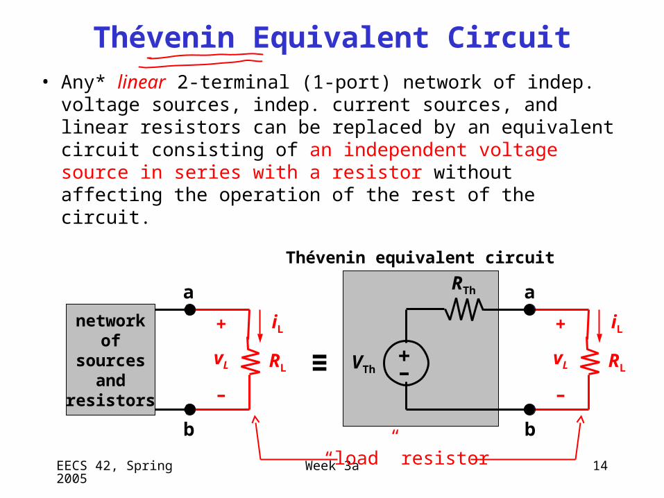
Thévenin Equivalent Circuit
• Any* linear 2-terminal (1-port) network of indep. voltage sources, indep. current sources, and linear resistors can be replaced by an equivalent circuit consisting of an independent voltage source in series with a resistor without affecting the operation of the rest of the circuit.
networkof
sourcesand
resistors
≡ –+
VTh
RTh
RL
iL+
vL
–
a
b
RL
iL+
vL
–
a
b
Thévenin equivalent circuit
“load” resistor
EECS 42, Spring 2005 Week 3a 15
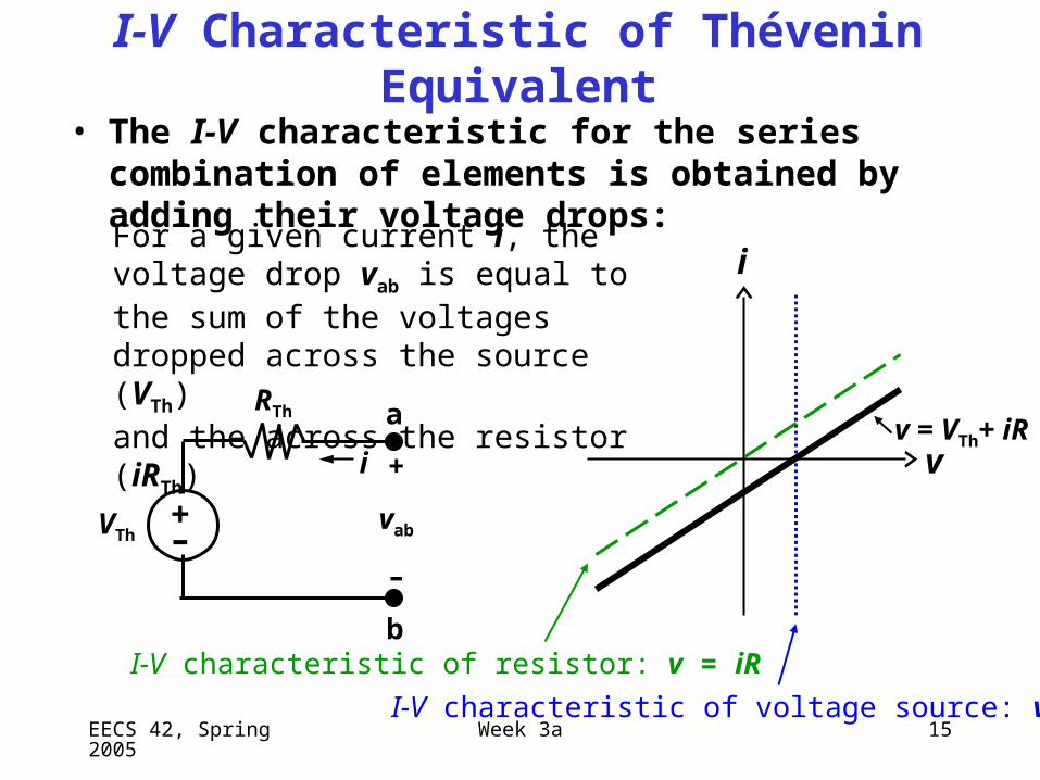
I-V Characteristic of Thévenin Equivalent
• The I-V characteristic for the series combination of elements is obtained by adding their voltage drops:
–+
VTh
RTh a
b
i
i
+
vab
–
v = VTh+ iR
I-V characteristic of resistor: v = iR
I-V characteristic of voltage source: v = VTh
For a given current i, the voltage drop vab is equal to the sum of the voltages dropped across the source (VTh)and the across the resistor (iRTh)
v
EECS 42, Spring 2005 Week 3a 16
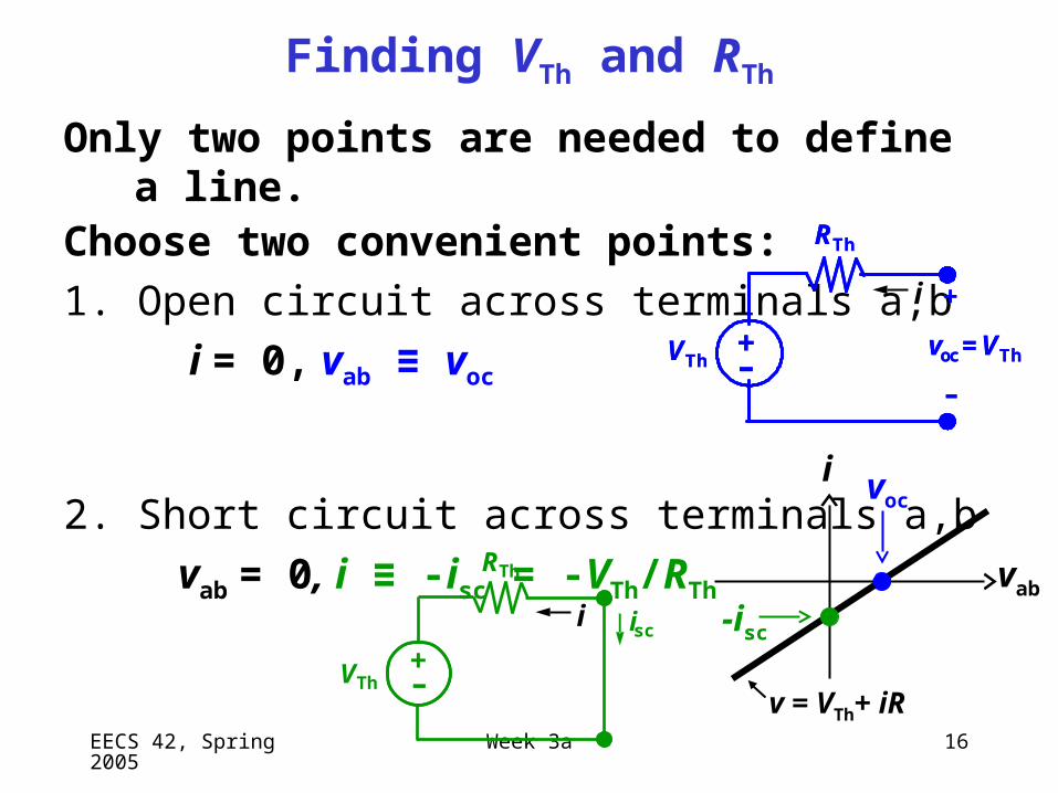
Finding VTh and RTh
Only two points are needed to define a line. Choose two convenient points:
1. Open circuit across terminals a,b
i = 0, vab ≡ voc
2. Short circuit across terminals a,b
vab = 0, i ≡ -isc = -VTh/RTh
–+
VTh
RTh
+
voc = VTh
––+
VTh
RTh
+
voc = VTh
–
i
v = VTh+ iR
vab
-isc
voc
–+
VTh
RTh
isci
i
EECS 42, Spring 2005 Week 3a 17
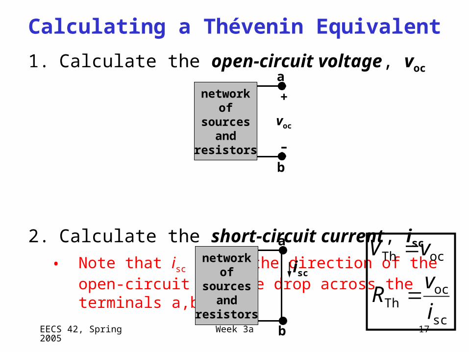
Calculating a Thévenin Equivalent
1. Calculate the open-circuit voltage, voc
2. Calculate the short-circuit current, isc
• Note that isc is in the direction of the open-circuit voltage drop across the terminals a,b !
networkof
sourcesand
resistors
a
b
+
voc
–
networkof
sourcesand
resistors
a
b
isc
sc
ocTh
ocTh
i
vR
vV
EECS 42, Spring 2005 Week 3a 18
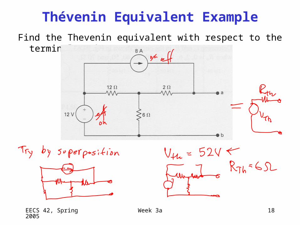
Thévenin Equivalent Example
Find the Thevenin equivalent with respect to the terminals a,b:

EECS 42, Spring 2005 Week 3a 19
EECS 42, Spring 2005 Week 3a 20
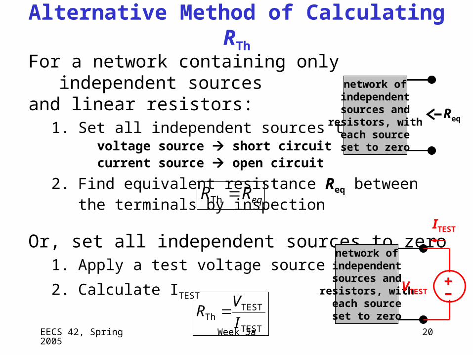
Alternative Method of Calculating RTh
For a network containing only independent sources and linear resistors:
1. Set all independent sources to zerovoltage source short circuitcurrent source open circuit
2. Find equivalent resistance Req between the terminals by inspection
Or, set all independent sources to zero1. Apply a test voltage source VTEST
2. Calculate ITEST
eqRR Th
TEST
TESTTh I
VR
network ofindependentsources and
resistors, witheach sourceset to zero
Req
network ofindependentsources and
resistors, witheach sourceset to zero
ITEST
–+
VTEST
EECS 42, Spring 2005 Week 3a 21
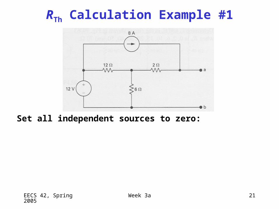
RTh Calculation Example #1
Set all independent sources to zero:

EECS 42, Spring 2005 Week 3a 22
Comments on Dependent Sources
A dependent source establishes a voltage or current whose value depends on the value of a voltage or current at a specified location in the circuit.
(device model, used to model behavior of transistors & amplifiers)
To specify a dependent source, we must identify:1. the controlling voltage or current (must be calculated, in general)2. the relationship between the controlling voltage or current and
the supplied voltage or current3. the reference direction for the supplied voltage or current
The relationship between the dependent sourceand its reference cannot be broken!
– Dependent sources cannot be turned off for various purposes (e.g. to find the Thévenin resistance, or in analysis using Superposition).
EECS 42, Spring 2005 Week 3a 23
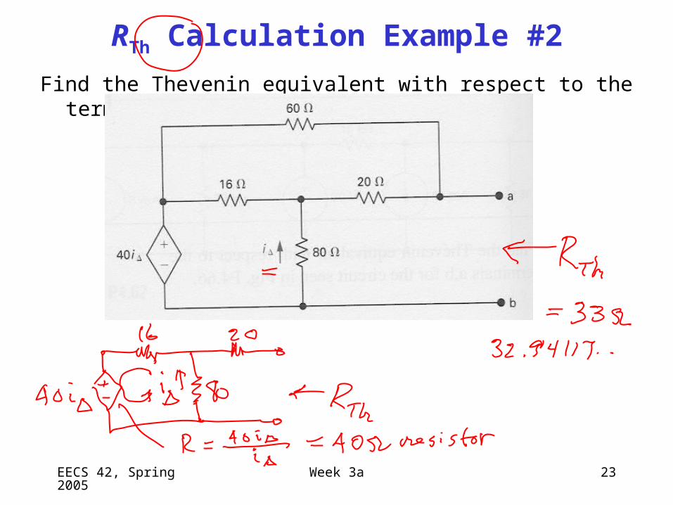
RTh Calculation Example #2
Find the Thevenin equivalent with respect to the terminals a,b:
EECS 42, Spring 2005 Week 3a 24
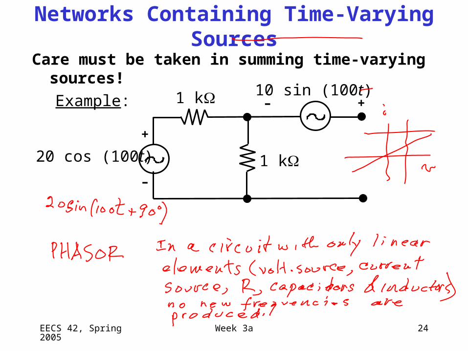
Networks Containing Time-Varying Sources
Care must be taken in summing time-varying sources!
Example:
20 cos (100t)
1 k
1 k
10 sin (100t)
+
–
– +
EECS 42, Spring 2005 Week 3a 25
Norton equivalent circuit
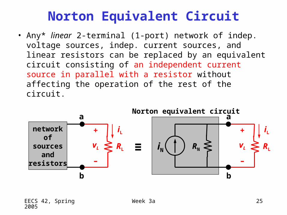
Norton Equivalent Circuit
• Any* linear 2-terminal (1-port) network of indep. voltage sources, indep. current sources, and linear resistors can be replaced by an equivalent circuit consisting of an independent current source in parallel with a resistor without affecting the operation of the rest of the circuit.
networkof
sourcesand
resistors
≡RL
iL+
vL
–
a
b
a
RL
iL+
vL
–
iN
b
RN
EECS 42, Spring 2005 Week 3a 26
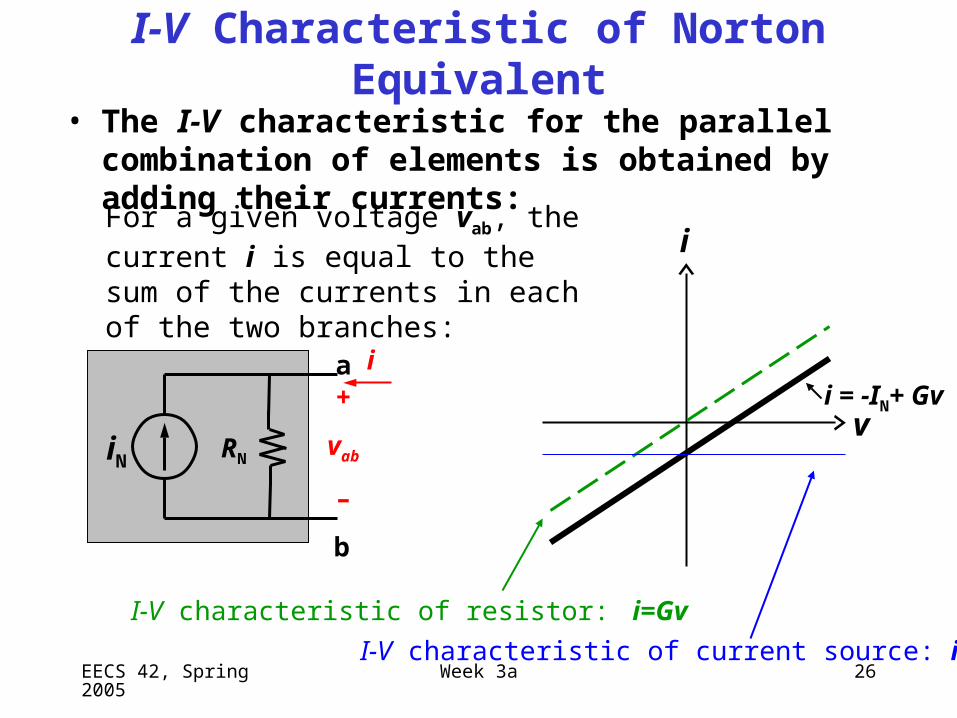
I-V Characteristic of Norton Equivalent
• The I-V characteristic for the parallel combination of elements is obtained by adding their currents:
i
i = -IN+ Gv
I-V characteristic of resistor: i=Gv
I-V characteristic of current source: i = -IN
For a given voltage vab, the current i is equal to the sum of the currents in each of the two branches:
v
i+
vab
–
iN
b
RN
a
EECS 42, Spring 2005 Week 3a 27
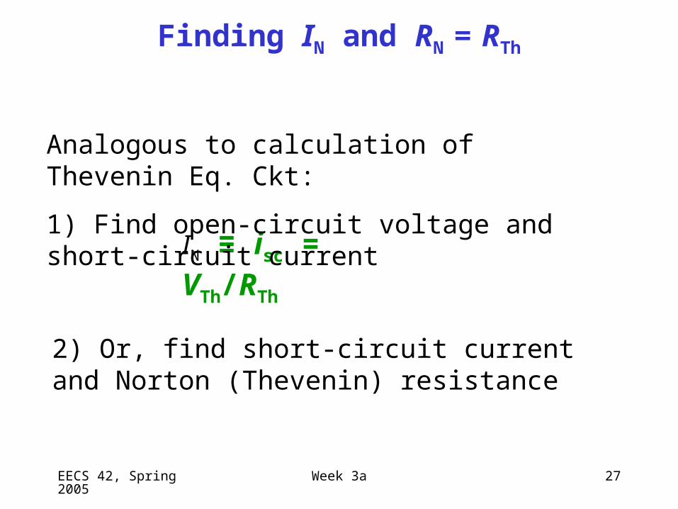
Finding IN and RN = RTh
IN ≡ isc = VTh/RTh
Analogous to calculation of Thevenin Eq. Ckt:
1) Find open-circuit voltage and short-circuit current
2) Or, find short-circuit current and Norton (Thevenin) resistance
EECS 42, Spring 2005 Week 3a 28
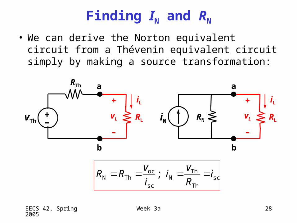
Finding IN and RN
• We can derive the Norton equivalent circuit from a Thévenin equivalent circuit simply by making a source transformation:
RLRN
iL
iN
+
vL
–
a
b
–+
RL
iL+
vL
–
vTh
RTh
scTh
ThN
sc
ocThN ; i
R
vi
i
vRR
a
b
EECS 42, Spring 2005 Week 3a 29
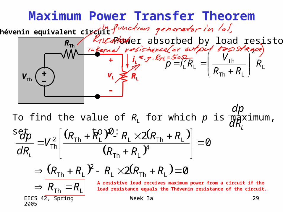
Maximum Power Transfer Theorem
A resistive load receives maximum power from a circuit if the load resistance equals the Thévenin resistance of the circuit.
L
2
LTh
ThL
2L R
RR
VRip
–+
VTh
RTh
RL
iL+
vL
–
Thévenin equivalent circuit
LTh
LThL2
LTh
4LTh
LThL2
LTh2Th
02
02
RR
RRRRR
RR
RRRRRV
dR
dp
L
To find the value of RL for which p is maximum, set to 0:
Power absorbed by load resistor:
LdR
dp

EECS 42, Spring 2005 Week 3a 30