Embed Size (px)
Citation preview
-EE494 POWER SYSTEMS -
• Professor:
– Dennis Hite.
• Presenters:
– Jürgen Sawatzki.
– Aaron Mashburn.
– Summer Emmons.
– Bryan Fernandez.
GEARLESS MAGNETIC WIND/SOLAR POWERED TURBINE STORAGE SYSTEM (GMAG-WINDSOPTSS)

U.S POWER CONSUMPTION
http://www.eia.gov/tools/faqs/faq.cfm?id=97&t=3
• Based on the U.S Energy Information Administration, theaverage annual residential electricity consumption for amodest U.S. home in 2012 was around 10,837 kWh.
• Louisiana had the highest annual consumption at 15,046kWh.
• Maine had the lowest annual consumption at 6,367 kWh.
• The average monthly residential electricity consumptionfor a modest U.S. home was around 903 kWh per month.
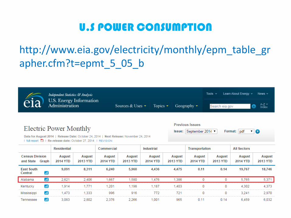
U.S POWER CONSUMPTION
http://www.eia.gov/electricity/monthly/epm_table_grapher.cfm?t=epmt_5_05_b

• The numbers on the previous slide shows a staggering number forrevenue in millions of dollars that electric companies earn byproviding electricity to consumer.
• This number is projected to increase exponentially in the next 20years due to population overgrowth in the U.S. as well asWorldwide.
• The majority of the sources used in generating this electricitypollute the environment and destroy the ecosystem.
• Unfortunately they are the only sources that can generate vastamounts of electricity for today’s demand.
• The minority of the other resources still do pollute the environmentbut not to a degree like the majority sources do. This is due to thefact that materials have to be made of elements, which in turn haveto be dug from the earth, and/or that in their manufacturingprocess release 𝐶𝑂2 into the environment.
U.S POWER CONSUMPTION

U.S NET GENERATION BY SOURCESJan 2010 - August 2010 (MWhx1000)
45%
24%
19%
7%
2% 1% 1% 1% 0%0%
Coal Natural Gas
Nuclear Hydro
Wind Petroleum
Wood Biomass
Geothermal Solar
http://www.eia.gov

• If the less pollutant sources are:– Hydro– Wind– Biomass– Geothermal– Solar
• Then one could state that it is crucial to increase the percentage of thesesources and to decrease the percentage of sources that pollute theenvironment.
• Therefore, the focus of this presentation is to demonstrate wind and/orsolar power can decrease the amount of pollutants being dumped into theatmosphere along with lowering to some extent or *completelyeliminating a household electric bill by relying on an off the gridalternative ; such as in the case of GMAG-WINDSOPTSS.
*Depends on user’s geographical location based on wind speed, and possiblescalability of GMAG-WINDSOPTSS.
U.S POWER CONSUMPTION

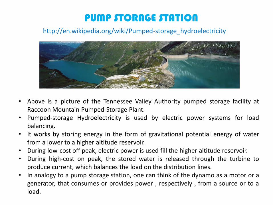
• A pump Storage station resembles a wind generator, withthe only difference that the flow of water is used torotate the rotor in order to produce electricity.
PUMP STORAGE STATION
http://thinkprogress.org/wp-content/uploads/2013/08/pump-storage-gr-555x206.jpeg
Dynamo
http://en.wikipedia.org/wiki/Pumped-storage_hydroelectricity
PUMP STORAGE STATION
• Above is a picture of the Tennessee Valley Authority pumped storage facility atRaccoon Mountain Pumped-Storage Plant.
• Pumped-storage Hydroelectricity is used by electric power systems for loadbalancing.
• It works by storing energy in the form of gravitational potential energy of waterfrom a lower to a higher altitude reservoir.
• During low-cost off peak, electric power is used fill the higher altitude reservoir.• During high-cost on peak, the stored water is released through the turbine to
produce current, which balances the load on the distribution lines.• In analogy to a pump storage station, one can think of the dynamo as a motor or a
generator, that consumes or provides power , respectively , from a source or to aload.

GEORGIA POWER ELECTRICAL SAFETY
• http://www.georgiapower.com/in-your-community/electric-safety/chart.cshtml
Electronic Watts-Hour (Wh) Amps-Hour (Ah) Small Appliances Watts-Hour (Wh) Amps-Hour (Ah)
Computer 300 2.50 Blender 300 2.50
Stereo 1,200 10 Box Fan 175 1.46
Television 150 1.25 Clock Radio 70 0.58
Major Appliances Watts-Hour (Wh) Amps-Hour (Ah) Coffee Maker 1,200 10
Baseboard Heater 1,600 13.33 Food Processor 200 1.67
Clothes Dryer 4,900 40.83 Hair Dryer 600 5
Dishwasher 1,200 10 Heating Blanket 200 1.67
Frost-Free Deep Freeze 500 4.17 Heating Pad 65 0.54
Frost-Free Refrigerator 615 5.13 Iron 1,100 9.17
Furnace 500 4.17 Microwave Oven 1,450 12.08
Garbage Disposal 450 to 950 3.75 to 7.92 Mixer 130 1.08
Oven 4,000 to 8,000 33.33 to 66.70 Sewing Machine 75 0.63
Range 4,000 to 5,000 33.33 to 41.70 Toaster 1,150 9.58
Room Heater 1,350 11.25Toaster/Toaster
Oven 1,150 9.58
Standard Deep Freeze 400 3.33
Two Burner Hot Plate 1,650 13.75
Standard Refrigerator 325 2.71 Vacuum Cleaner 750 to 1,350 6.25 to 11.25
Washing Machine 500 4.17
Water Heater 2,000 to 5,000 16.70 to 41.70
GEARLESS MAGNETIC WIND-SOLAR POWERED TURBINE
Mission:
To design and implement an operable proto-type ofa gearless Magnetic Levitated Wind/Solar PoweredSpiral Axis Turbine powering a dual storage system(Flywheel Energy Storage + Array of Batteries),delivering a “steady” auxiliary power to the user’shome grid in emergency scenarios; such as whenpower from the grid has either failed or is notavailable at all.
WHY CHOOSE TO DESIGN A TURBINE?
• Wind Turbine Designs are commercially available,therefore, it is easier to improve upon an existingdesign.
• To apply concepts learned by team members in theareas of: Electrical and Mechanical Engineering.
• To create a backup emergency system, that willcommercially rival those available 3-10kW Powergenerators in: cost, maintenance, energy delivery, andtrue cost to own.
• To help deliver a “semi-favorable” impact on theenvironment based on wind energy. (Lead-AcidBatteries and the process of designing solar panels areNOT environmentally friendly).
WHAT WILL THE DESIGN CONSIST OF?
• The use of 1 DC current source: array of Mono-Crystalline solarpanels.
• The use of 2 source 3∅ Phase AC generators: WPG and FES.• 1 power inverter circuit, located between the array of batteries
and the home.• 1 charge controller circuit, located at the input of the battery
array.• 1 Rectifier circuit, located at the input of the charge controller.• 1 Frequency converter located at the output of the FES.• A Turbine blade design based on the “Liam F1 UWT” model by
The Archimedes BV -RDM Campus, in the Netherlands.• Sources of Wind and Solar. For a combined efficiency (𝐸𝑓)
of: 28% <𝐸𝑓< 44%.

• Use of 4 High Powered semi-flexible Mono-Crystalline Solar Cells to provide 1.2 kW of power.
• Arduino-One Micro-controller to be interfacedbetween all circuits to read data from them, and tocontrol the direction of current flow through theuse of several switches.
• A small scale flywheel Energy Storage system tostore the electrical energy converted by the windpowered generator into angular kinetic energy.
• A set of 4 parallel connected 250Ah batteries.
WHAT WILL THE DESIGN CONSIST OF?
DESIGNING STEPS
• Upscaling/downscaling available designs for the inverter, turbine blades,charge controller, frequency converter and power inverter to meet thisproject requirements in MULTISIM.
• To Calculate Power losses along individual circuit modules.• Integrating switches in the design schematics to: disconnect wind powered
generator in excess winds (allowing the turbine to cruise freely), to switchbetween FES charging the battery array or delivering power to the home, toswitch between the wind powered generator charging the battery array orthe solar cells array charging the battery array.
• Create a prototype of the FES in solid edge, run a stress analysis on it usingFEMAP, then built it at the UAH Machine Shop.
• Creating a model of the spiral axis turbine blade in Solid Edge, run a CFDanalysis, and a stress analysis using FEMAP, then built it at the UAHMachine Shop.
• After either FES or SAWSPT has been machined, run a real stress analysis onboth structures.
• Write the code in C++ to be used with the Arduino One to monitor themodules.

• Winds of at least 10 mph are needed to generateusable energy(20% Ef).
• Solar panels will not work at night.• System will only work in single mode (Wind) during
night or it wont work at all till daylight (depending onthe wind conditions at night, altitude of turbine, etc.).
• Limited access to UAH’s machine shop during 2015year.
DESIGNING PROBLEMS?
WHAT TO DETERMINE?
• Money that the group has available + Sponsorships money.
• Use GOFUNDME to have the teams project sponsored.• Geographical area of interest where the turbine will
function as expected.• Wind speeds of the selected demographical area.• The overall efficiency of the system based on power
stored and delivered by the different modules, and of power losses throughout the system.
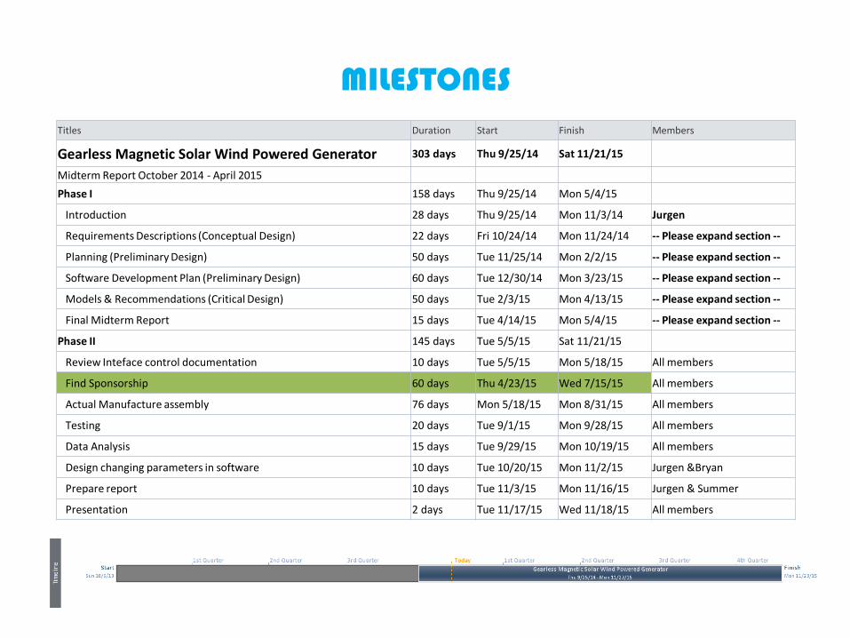
MILESTONESTitles Duration Start Finish Members
Gearless Magnetic Solar Wind Powered Generator 303 days Thu 9/25/14 Sat 11/21/15
Midterm Report October 2014 - April 2015
Phase I 158 days Thu 9/25/14 Mon 5/4/15
Introduction 28 days Thu 9/25/14 Mon 11/3/14 Jurgen
Requirements Descriptions (Conceptual Design) 22 days Fri 10/24/14 Mon 11/24/14 -- Please expand section --
Planning (Preliminary Design) 50 days Tue 11/25/14 Mon 2/2/15 -- Please expand section --
Software Development Plan (Preliminary Design) 60 days Tue 12/30/14 Mon 3/23/15 -- Please expand section --
Models & Recommendations (Critical Design) 50 days Tue 2/3/15 Mon 4/13/15 -- Please expand section --
Final Midterm Report 15 days Tue 4/14/15 Mon 5/4/15 -- Please expand section --
Phase II 145 days Tue 5/5/15 Sat 11/21/15
Review Inteface control documentation 10 days Tue 5/5/15 Mon 5/18/15 All members
Find Sponsorship 60 days Thu 4/23/15 Wed 7/15/15 All members
Actual Manufacture assembly 76 days Mon 5/18/15 Mon 8/31/15 All members
Testing 20 days Tue 9/1/15 Mon 9/28/15 All members
Data Analysis 15 days Tue 9/29/15 Mon 10/19/15 All members
Design changing parameters in software 10 days Tue 10/20/15 Mon 11/2/15 Jurgen &Bryan
Prepare report 10 days Tue 11/3/15 Mon 11/16/15 Jurgen & Summer
Presentation 2 days Tue 11/17/15 Wed 11/18/15 All members

GEARLESS MAGNETIC WIND-SOLAR POWERED TURBINE STORAGE SYSTEM (GMAG-WINDSOPTSS)
FREQUENCY CONVERTER
120 VAC
RECTIFIER
POWER INVERTER
CHARGE CONTROLLER
18
0
45
9 7
63
2
*Paths 2-8 or 2,3,8 may be optional.
Dashed lines refer to optional modules.

GEARLESS MAGNETIC WIND-SOLAR POWERED TURBINE STORAGE SYSTEM (GMAG-WINDSOPTSS)
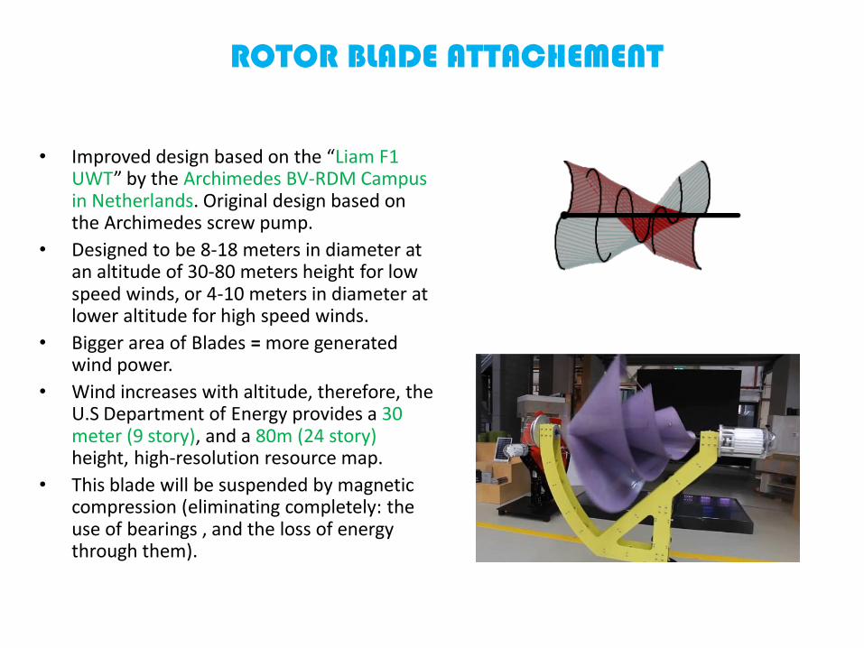
• Improved design based on the “Liam F1 UWT” by the Archimedes BV-RDM Campus in Netherlands. Original design based on the Archimedes screw pump.
• Designed to be 8-18 meters in diameter at an altitude of 30-80 meters height for low speed winds, or 4-10 meters in diameter at lower altitude for high speed winds.
• Bigger area of Blades = more generated wind power.
• Wind increases with altitude, therefore, the U.S Department of Energy provides a 30 meter (9 story), and a 80m (24 story) height, high-resolution resource map.
• This blade will be suspended by magnetic compression (eliminating completely: the use of bearings , and the loss of energy through them).
ROTOR BLADE ATTACHEMENT

• The SAWT is not suited for turbulent urban winds. This is due that the turbine is designed to be at an angle of attack of 60°to catch the wind.
• The turbine always turns itself in the direction of the wind.
• The energy arises because the wind is rotated by the blades by 90°. This results in almost no resistance on the blades, therefore the turbine is almost noiseless.
• The large surface area of the turbine blade translates into a higher 𝐶𝑝 value of efficiency, due to the bigger area of the blades capturing more wind.
• The Beaufort scale of the wind in Huntsville, Alabama is force 3 on a scale of 12.
• Small wind turbines do operate between force 3 and force 7.
ROTOR BLADE ATTACHEMENT

THE LIAM F1 SAWPT

SAWPT STRUCTURAL ANALYSIS

4mps = 8.95 mph winds

4mps = 8.95 mph winds

Alabama Average Wind Speed County Rank
Rank Average Wind Speed County / Population
1 18.60 mph Bullock, AL / 10,914
2 18.14 mph Barbour, AL / 27,457
3 17.89 mph Russell, AL / 52,947
4 17.34 mph Pike, AL / 32,899
5 16.98 mph Macon, AL / 21,452
6 16.92 mph Henry, AL / 17,302
7 16.84 mph Jackson, AL / 53,227
8 16.50 mph Montgomery, AL / 229,363
9 16.50 mph De Kalb, AL / 71,109
10 16.38 mph Crenshaw, AL / 13,906
11 16.18 mph Etowah, AL / 104,430
12 16.14 mph Cherokee, AL / 25,989
13 16.05 mph Dale, AL / 50,251
14 15.71 mph Coffee, AL / 49,948
15 15.67 mph Elmore, AL / 79,303
16 15.65 mph Walker, AL / 67,023
17 15.55 mph Marengo, AL / 21,027
18 15.52 mph Morgan, AL / 119,490
19 15.51 mph Lee, AL / 140,247
20 15.47 mph Lowndes, AL / 11,299
21 15.47 mph Hale, AL / 15,760
22 15.34 mph Marshall, AL / 93,019
23 15.28 mph Butler, AL / 20,947
24 15.25 mph Greene, AL / 9,045
25 15.15 mph Dallas, AL / 43,820
26 15.14 mph Tuscaloosa, AL / 194,656
27 15.11 mph Saint Clair, AL / 83,593
28 15.04 mph Fayette, AL / 17,241
29 15.04 mph Cullman, AL / 80,406
30 15.01 mph Tallapoosa, AL / 41,616
31 14.98 mph Conecuh, AL / 13,228
32 14.90 mph Chambers, AL / 34,215
33 14.81 mph Escambia, AL / 38,319
Rank Average Wind Speed County / Population
34 14.80 mph Madison, AL / 334,811
35 14.70 mph Wilcox, AL / 11,670
36 14.64 mph Sumter, AL / 13,763
37 14.54 mph Blount, AL / 57,322
38 14.53 mph Winston, AL / 24,484
39 14.53 mph Perry, AL / 10,591
40 14.49 mph Houston, AL / 101,547
41 14.47 mph Calhoun, AL / 118,572
42 14.42 mph Bibb, AL / 22,915
43 14.31 mph Pickens, AL / 19,746
44 14.22 mph Jefferson, AL / 658,466
45 14.19 mph Lamar, AL / 14,564
46 14.13 mph Covington, AL / 37,765
47 14.12 mph Monroe, AL / 23,068
48 14.04 mph Coosa, AL / 11,539
49 13.99 mph Lawrence, AL / 34,339
50 13.96 mph Franklin, AL / 31,704
51 13.79 mph Cleburne, AL / 14,972
52 13.78 mph Shelby, AL / 195,085
53 13.75 mph Autauga, AL / 54,571
54 13.73 mph Marion, AL / 30,776
55 13.64 mph Limestone, AL / 82,782
56 13.55 mph Choctaw, AL / 13,859
57 13.41 mph Chilton, AL / 43,643
58 13.35 mph Randolph, AL / 22,913
59 13.30 mph Colbert, AL / 54,428
60 13.20 mph Geneva, AL / 26,790
61 13.19 mph Clay, AL / 13,932
62 13.16 mph Lauderdale, AL / 92,709
63 12.96 mph Baldwin, AL / 182,265
64 12.84 mph Clarke, AL / 25,833
65 12.69 mph Mobile, AL / 412,992
66 12.58 mph Talladega, AL / 82,291
67 12.15 mph Washington, AL / 17,581
http://www.usa.com/rank/alabama-state--average-wind-speed--county-rank.htm

ROTOR BLADE SUPORTING FRAME (TOP)
Strong rare magnetPushing down on magnet #2. Magnets 1 and 2 are axially
magnetized.
1
2
3
4
Strong rare magnet containing magnet #3 inside its magnetic
field. Magnets 3 and 4 are radially magnetized.
Slider arm, can be adjusted at any height.

ROTOR BLADE SUPPORTING FRAME (BOTTOM)
5
6
7
8
Strong rare magnet containing magnet #6 inside its magnetic
field. Magnets 5 and 6 are radially magnetized.
Strong rare magnetPushing up on magnet #7.
Magnets 7 and 8 are axially magnetized.
Slider arm, can be adjusted at any height.

ROTOR BLADE FRAME MODIFICATIONS
• Frame to support Spiral AxisWind Turbine in vertical orhorizontal configuration as toemulate a HAWT or a VAWTturbine.
• Achieved by the use of anAltazimuth mount to controlthe altitude of the turbine, justlike a Dobsonian telescope.
http://en.wikipedia.org/wiki/Altazimuth_mount
ROTOR BLADE ATTACHEMENT
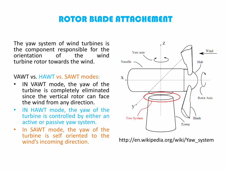
The yaw system of wind turbines isthe component responsible for theorientation of the windturbine rotor towards the wind.
VAWT vs. HAWT vs. SAWT modes:• IN VAWT mode, the yaw of the
turbine is completely eliminatedsince the vertical rotor can facethe wind from any direction.
• IN HAWT mode, the yaw of theturbine is controlled by either anactive or passive yaw system.
• In SAWT mode, the yaw of theturbine is self oriented to thewind’s incoming direction. http://en.wikipedia.org/wiki/Yaw_system

ROTOR BLADE ATTACHEMENT
The

ROTOR BLADE ATTACHEMENT
ROTOR BLADE ATTACHEMENT
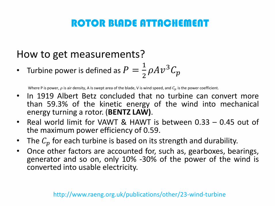
How to get measurements?
• Turbine power is defined as 𝑃 =1
2𝜌𝐴𝑣3𝐶𝑝
Where P is power, 𝜌 is air density, A Is swept area of the blade, V is wind speed, and 𝐶𝑝 is the power coefficient.
• In 1919 Albert Betz concluded that no turbine can convert morethan 59.3% of the kinetic energy of the wind into mechanicalenergy turning a rotor. (BENTZ LAW).
• Real world limit for VAWT & HAWT is between 0.33 – 0.45 out ofthe maximum power efficiency of 0.59.
• The 𝐶𝑝 for each turbine is based on its strength and durability.• Once other factors are accounted for, such as, gearboxes, bearings,
generator and so on, only 10% -30% of the power of the wind isconverted into usable electricity.
http://www.raeng.org.uk/publications/other/23-wind-turbine
ROTOR BLADE ATTACHEMENT
How to get measurements?
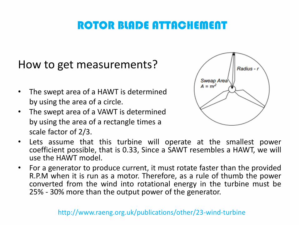
• The swept area of a HAWT is determinedby using the area of a circle.
• The swept area of a VAWT is determinedby using the area of a rectangle times ascale factor of 2/3.
• Lets assume that this turbine will operate at the smallest powercoefficient possible, that is 0.33, Since a SAWT resembles a HAWT, we willuse the HAWT model.
• For a generator to produce current, it must rotate faster than the providedR.P.M when it is run as a motor. Therefore, as a rule of thumb the powerconverted from the wind into rotational energy in the turbine must be25% - 30% more than the output power of the generator.
http://www.raeng.org.uk/publications/other/23-wind-turbine
ROTOR BLADE ATTACHEMENT
How to get measurements?
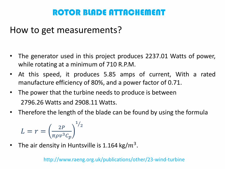
• The generator used in this project produces 2237.01 Watts of power,while rotating at a minimum of 710 R.P.M.
• At this speed, it produces 5.85 amps of current, With a ratedmanufacture efficiency of 80%, and a power factor of 0.71.
• The power that the turbine needs to produce is between
2796.26 Watts and 2908.11 Watts.
• Therefore the length of the blade can be found by using the formula
𝐿 = 𝑟 =2𝑃
𝜋𝜌𝑣3𝐶𝑝
1 2
• The air density in Huntsville is 1.164 kg/𝑚3.
http://www.raeng.org.uk/publications/other/23-wind-turbine
ROTOR BLADE ATTACHEMENT
How to get measurements?
http://www.raeng.org.uk/publications/other/23-wind-turbine
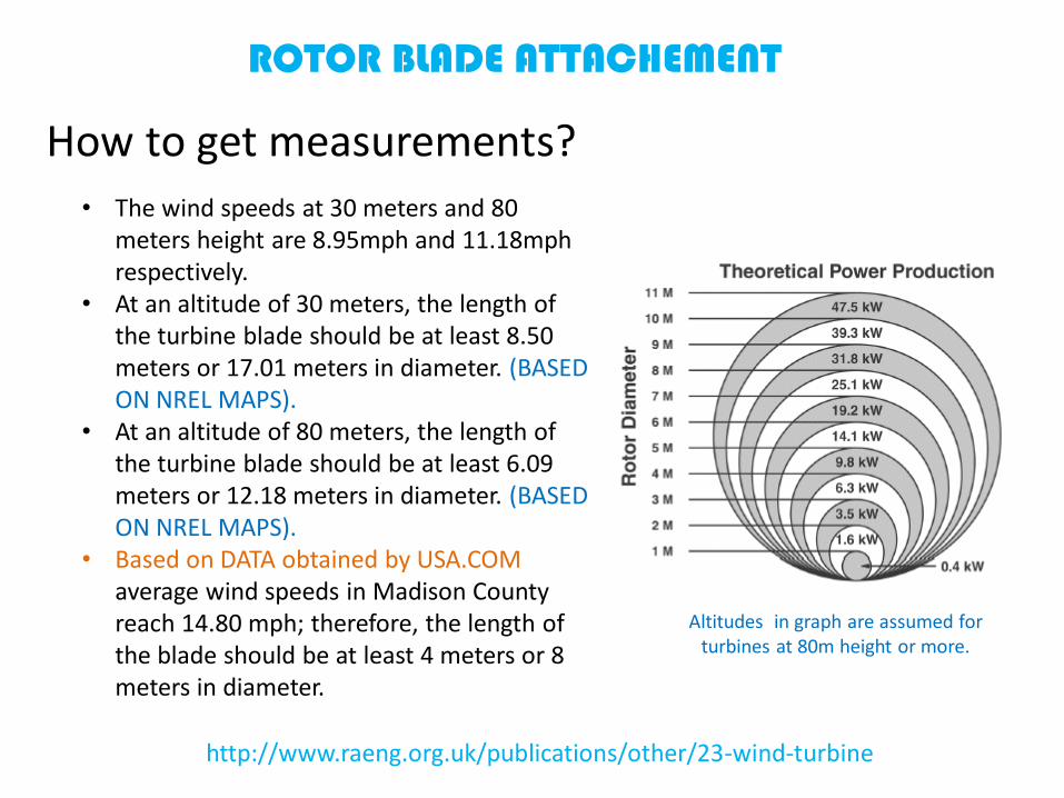
• The wind speeds at 30 meters and 80 meters height are 8.95mph and 11.18mph respectively.
• At an altitude of 30 meters, the length of the turbine blade should be at least 8.50 meters or 17.01 meters in diameter. (BASED ON NREL MAPS).
• At an altitude of 80 meters, the length of the turbine blade should be at least 6.09 meters or 12.18 meters in diameter. (BASED ON NREL MAPS).
• Based on DATA obtained by USA.COM average wind speeds in Madison County reach 14.80 mph; therefore, the length of the blade should be at least 4 meters or 8 meters in diameter.
Altitudes in graph are assumed for turbines at 80m height or more.

ROTOR BLADE ATTACHEMENT
Pros & Cons
• Ideal for small areas and rooftops.
• Aesthetically pleasing.
• Obtaining free wind power.
• Magnetically levitated = no friction from bearings.
• Efficiency of a VAWT is 2/3 less than a HAWT due toblade design and fluid dynamics.
• May be damaged by excessive high winds.
• Construction needs to be lightweight.
• Long construction time.

AC GENERATOR
What is an induction motor?
• An induction or asynchronous motor is an AC electricmotor in which the electric current in the rotorneeded to produce torque is obtained byelectromagnetic induction from the magnetic field ofthe stator winding.
• An AC induction motor consists of two assemblies - astator and a rotor. The interaction of currents flowingin the rotor bars and the stators' rotating magneticfield generates a torque. In an actual operation, therotor speed always lags the magnetic field's speed,allowing the rotor bars to cut magnetic lines of forceand produce useful torque.
• The difference between the synchronous speed of themagnetic field, and the shaft rotating speed is slip -and would be some number of RPM or frequency.
• The slip increases with an increasing load, thusproviding a greater torque.
AC GENERATOR
What is an induction motor?
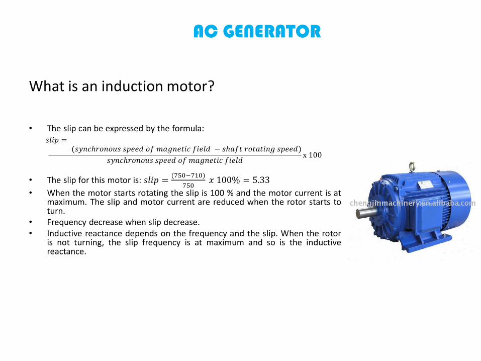
• The slip can be expressed by the formula:𝑠𝑙𝑖𝑝 =
(𝑠𝑦𝑛𝑐ℎ𝑟𝑜𝑛𝑜𝑢𝑠 𝑠𝑝𝑒𝑒𝑑 𝑜𝑓 𝑚𝑎𝑔𝑛𝑒𝑡𝑖𝑐 𝑓𝑖𝑒𝑙𝑑 − 𝑠ℎ𝑎𝑓𝑡 𝑟𝑜𝑡𝑎𝑡𝑖𝑛𝑔 𝑠𝑝𝑒𝑒𝑑)
𝑠𝑦𝑛𝑐ℎ𝑟𝑜𝑛𝑜𝑢𝑠 𝑠𝑝𝑒𝑒𝑑 𝑜𝑓 𝑚𝑎𝑔𝑛𝑒𝑡𝑖𝑐 𝑓𝑖𝑒𝑙𝑑x 100
• The slip for this motor is: 𝑠𝑙𝑖𝑝 =(750−710)
750𝑥 100% = 5.33
• When the motor starts rotating the slip is 100 % and the motor current is atmaximum. The slip and motor current are reduced when the rotor starts toturn.
• Frequency decrease when slip decrease.• Inductive reactance depends on the frequency and the slip. When the rotor
is not turning, the slip frequency is at maximum and so is the inductivereactance.
AC GENERATOR
What is an induction motor?
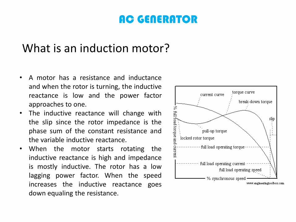
• A motor has a resistance and inductanceand when the rotor is turning, the inductivereactance is low and the power factorapproaches to one.
• The inductive reactance will change withthe slip since the rotor impedance is thephase sum of the constant resistance andthe variable inductive reactance.
• When the motor starts rotating theinductive reactance is high and impedanceis mostly inductive. The rotor has a lowlagging power factor. When the speedincreases the inductive reactance goesdown equaling the resistance.

AC GENERATOR
Why choose this model?
• Same quality as products being manufacturedin U.S or Europe.
• Lower price in China vs. U.S. vs. Europe.• Polyphase Squirrel-Cage induction motor
(Asynchronous motor) is used commonly inthe wind power industry; when operated inreverse acting as a generator.
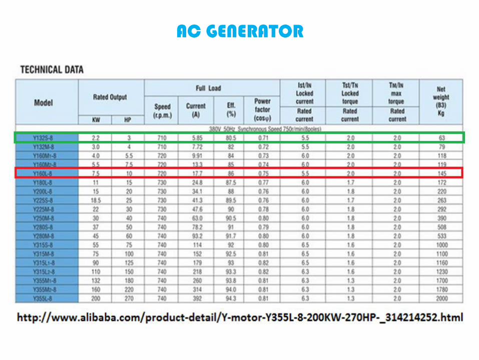
• Model Y132S-8 provides 3 HP of power =2237.01 Watts.
AC GENERATOR
AC GENERATOR
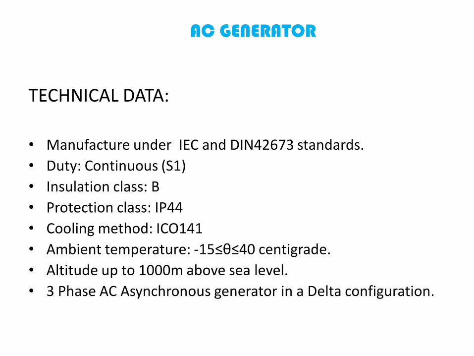
TECHNICAL DATA:
• Manufacture under IEC and DIN42673 standards.
• Duty: Continuous (S1)
• Insulation class: B
• Protection class: IP44
• Cooling method: ICO141
• Ambient temperature: -15≤θ≤40 centigrade.
• Altitude up to 1000m above sea level.
• 3 Phase AC Asynchronous generator in a Delta configuration.
AC GENERATOR
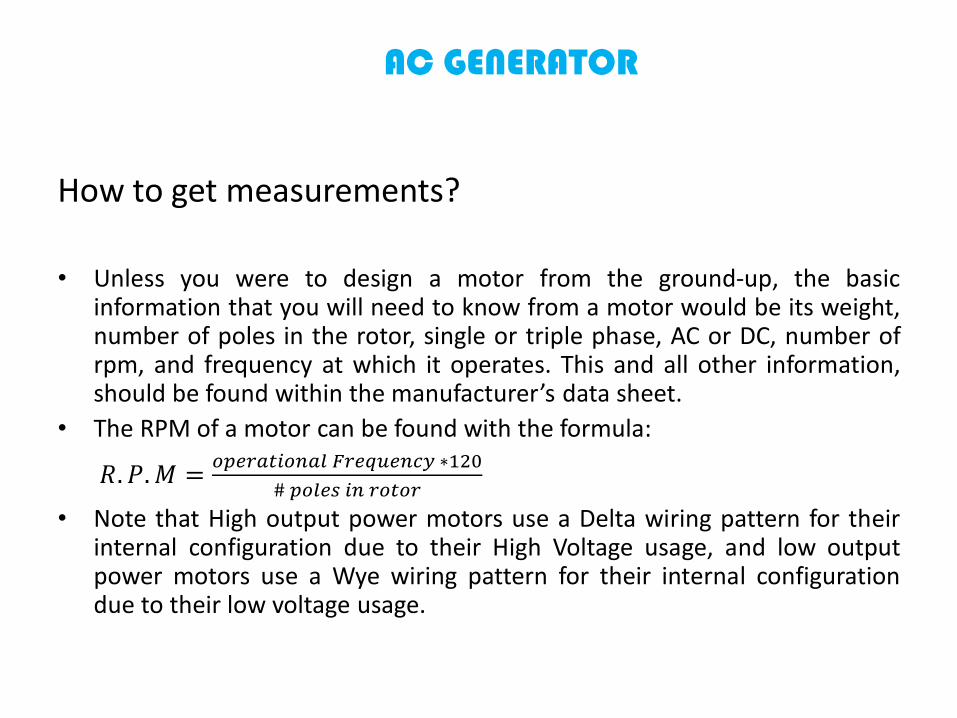
How to get measurements?
• Unless you were to design a motor from the ground-up, the basicinformation that you will need to know from a motor would be its weight,number of poles in the rotor, single or triple phase, AC or DC, number ofrpm, and frequency at which it operates. This and all other information,should be found within the manufacturer’s data sheet.
• The RPM of a motor can be found with the formula:
𝑅. 𝑃.𝑀 =𝑜𝑝𝑒𝑟𝑎𝑡𝑖𝑜𝑛𝑎𝑙 𝐹𝑟𝑒𝑞𝑢𝑒𝑛𝑐𝑦 ∗120
# 𝑝𝑜𝑙𝑒𝑠 𝑖𝑛 𝑟𝑜𝑡𝑜𝑟
• Note that High output power motors use a Delta wiring pattern for theirinternal configuration due to their High Voltage usage, and low outputpower motors use a Wye wiring pattern for their internal configurationdue to their low voltage usage.

AC GENERATOR SCHEMATIC
Animated example of a 3 Phase, 12 pole motor.
Example of a 3 Phase, 8 pole motor in a Delta configuration to
handle higher voltage.

Pros & Cons• Obtaining free wind power from rotor blade attachment.• Cheaper in price than a Synchronous motor.• Lagging power factor may be low at light loads.• Self-Starting motor.• No excitation required for the rotor.• May be damaged by excessive high winds.• Has to be opened and modified so that the turbine blades can be attached to the
rotor.• Bearings between rotor and stator has to be removed due to the rotor being
magnetically levitated.• Very heavy ~140 Lbs.• With increase or decrease in rotating speed, the generated AC frequency changes.• Generator creates an AC current with a Lagging power factor, high at heavy loads.• Requires 710 or more R.P.M to become higher efficient.
AC GENERATOR
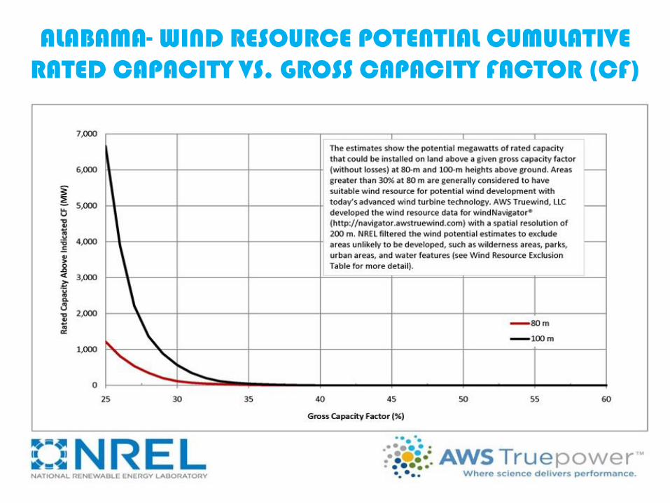
ALABAMA- WIND RESOURCE POTENTIAL CUMULATIVE RATED CAPACITY VS. GROSS CAPACITY FACTOR (CF)

ECONOMIC ESTIMATES FOR SMALL WIND TURBINES

ANEMOMETER
• An anemometer is a device thatmeasures wind speed. It is acommonly used weather stationinstrument. His name comesfrom the Greek word anemos,meaning wind, and is used todescribe any air speedmeasurement instrument usedin meteorology oraerodynamics.
http://en.wikipedia.org/wiki/Anemometer
SOLAR CELLS
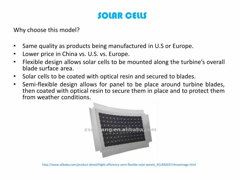
Why choose this model?
• Same quality as products being manufactured in U.S or Europe.• Lower price in China vs. U.S. vs. Europe.• Flexible design allows solar cells to be mounted along the turbine’s overall
blade surface area.• Solar cells to be coated with optical resin and secured to blades.• Semi-flexible design allows for panel to be place around turbine blades,
then coated with optical resin to secure them in place and to protect themfrom weather conditions.
http://www.alibaba.com/product-detail/Hight-efficiency-semi-flexible-solar-panels_451492037/showimage.html

ENCAPSULATING SOLAR CELLS
http://www.smooth-on.com/a103/New-Solaris%3D-Clear-Encapsulatingsilicone/article_info.html
• Optically clear platinum silicone that lets light pass thorough it unimpeded.• Mixed 1A:1B by volume .• Features a low viscosity and de-airs itself well.• To aid in de-airing, the pot life is an extra-long 240 minutes.• The rubber cures optically clear in 24 hours at room temperature.
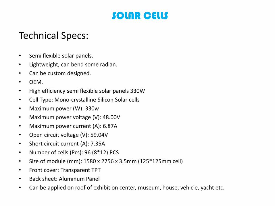
Technical Specs:
• Semi flexible solar panels.
• Lightweight, can bend some radian.
• Can be custom designed.
• OEM.
• High efficiency semi flexible solar panels 330W
• Cell Type: Mono-crystalline Silicon Solar cells
• Maximum power (W): 330w
• Maximum power voltage (V): 48.00V
• Maximum power current (A): 6.87A
• Open circuit voltage (V): 59.04V
• Short circuit current (A): 7.35A
• Number of cells (Pcs): 96 (8*12) PCS
• Size of module (mm): 1580 x 2756 x 3.5mm (125*125mm cell)
• Front cover: Transparent TPT
• Back sheet: Aluminum Panel
• Can be applied on roof of exhibition center, museum, house, vehicle, yacht etc.
SOLAR CELLS

SOLAR CELLS
Circuit Schematic of Solar Cells Array

SOLAR CELLS
Pros & Cons
• Lower unit price when buying from China.
• Panels are not encapsulated.
• Shipping time is longer.

BATTERIES
Why choose this model?
• Same quality as products being manufactured in U.S orEurope.
• Lower price in China vs. U.S. vs. Europe.• Batteries are rated for 250Ah at 12 VDC.
http://www.alibaba.com/product-detail/250A-12V-Gelled-High-Efficient-Solar_1969655706.html

Technical Specs:
• Weights 72 Kgs.
• OEM.
• Cell Type: Gelled Solar battery
• Maximum power (W): 3000w
• Capacity of Battery: 250Ah
• Number of cells (Pcs): 6
• Size of module (mm): 523x268x220mm
• Nominal Voltage: 12V
• Lead battery Type
• Fully Charged battery 77°F(25°C): 4mΩ
• Discharge: -20~60°C
• Charge: -10~60°C
• Storage:-20~60°C
BATTERIES

Circuit Schematic for Battery Array
BATTERIES
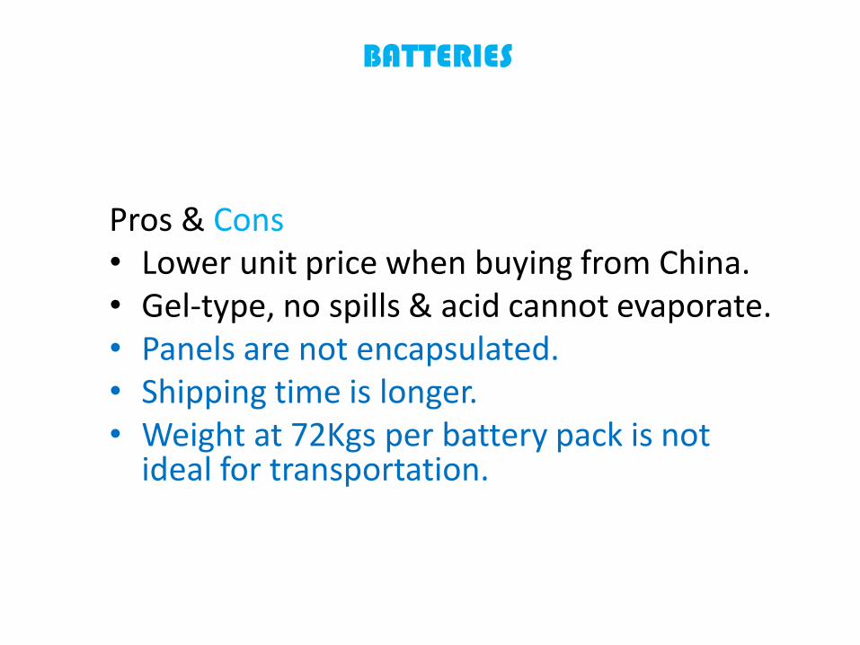
Pros & Cons• Lower unit price when buying from China.• Gel-type, no spills & acid cannot evaporate.• Panels are not encapsulated.• Shipping time is longer.• Weight at 72Kgs per battery pack is not
ideal for transportation.
BATTERIES

FREQUENCY CONVERTER
What is a Frequency Converter?
• A frequency converter is an electronic device that converts AC of one frequency to AC ofanother frequency.
• A frequency converter consist of a rectifier stage (producing direct current) which is theninverted to produce AC of the desired frequency. The inverter may use thyristors, IGCTsor IGBTs.
• Frequency changers are used in the airline industries. Often airplanes use 400 Hz power,so a 50 Hz or 60 Hz to 400 Hz frequency converter is needed for use in the ground powerunit (unit used to power the airplane while it is on the ground).
• Frequency changers are also used in renewable energy systems. They are an essentialcomponent of doubly fed induction generators (DFIGs) as used in modern multi-megawatt class wind turbines. A Doubly fed electric machines is an electric generatorsthat have windings on both stationary and rotating parts, where both windings transfersignificant power between shaft and electrical system.
• For this project a frequency converter will be use to regulate the frequency that the FESis running at and convert it to 60 Hz (U.S and Japan standard).
http://en.wikipedia.org/wiki/Frequency_changerhttp://en.wikipedia.org/wiki/Doubly_fed_electric_machine

FREQUENCY CONVERTER SCHEMATIC
THIS DESIGN IS FOR ILLUSTRATION PURPOSES ONLY

Pros & Cons
• Cheaper, since it is home built.
• Schematic is hard to understand.
• Soldering and testing components onto board is time consuming.
• Current design needs to be downscale or upscale to meet the projects' initial conditions.
FREQUENCY CONVERTER
RECTIFIER
What is a Rectifier?
• A rectifier is an electrical device that converts AC toDC.
• A full-wave rectifier converts the whole of the inputwaveform to one of constant polarity (positive ornegative) at its output.
• The rectifier used in this project will be a 3 Phase Full-wave rectifier using six Thrysistors (SCR’S: siliconcontrolled rectifiers), instead of diodes, due to thelarge current flowing in them.
http://en.wikipedia.org/wiki/Rectifierhttp://en.wikipedia.org/wiki/Thyristor
RECTIFIER SCHEMATIC
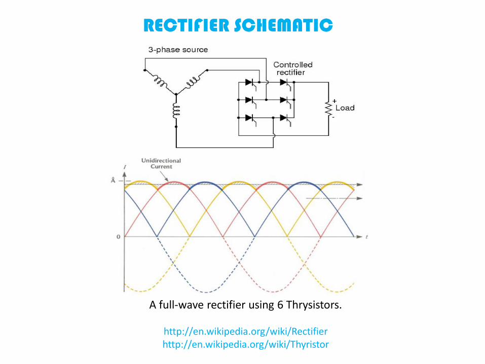
A full-wave rectifier using 6 Thrysistors.
http://en.wikipedia.org/wiki/Rectifierhttp://en.wikipedia.org/wiki/Thyristor

Pros & Cons• Cheaper, since it is home built.• Schematic is easy to understand.• Soldering and testing components onto board is
time consuming.• Current design needs to be downscale or upscale
to meet the projects' initial conditions.• SCR gates are expensive.
RECTIFIER

CHARGE CONTROLLER
What is a Charge Controller?
• A charge controller is a circuit that limits the rate at which electric current is added to or drawn from electric batteries.
• It prevents overcharging and may protect against overvoltage, which can reduce battery performance or lifespan, and may pose a safety risk.
• It may also prevent completely draining ("deep discharging") a battery.
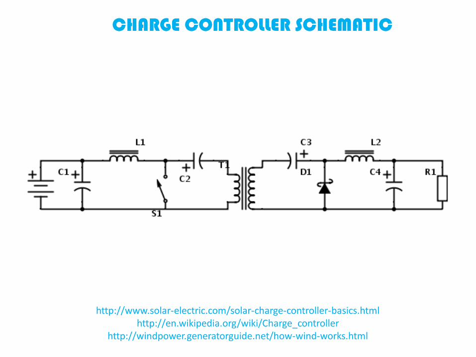
• The charge controller for this project will use a PWM regulator. This PWM regulator is called an isolated Ćuk converter.
http://www.solar-electric.com/solar-charge-controller-basics.htmlhttp://en.wikipedia.org/wiki/Charge_controller

CHARGE CONTROLLER
What is a Cok Converter?
• A Cok converter is a type of DC-DC converter that has an output voltagemagnitude that is either greater than or less than the input voltagemagnitude.
• It is essentially a boost converter followed by a buck converter with acapacitor to couple the energy (aka: it can provide a charge within a widerange of winds).
• The difference between isolated and non-isolated Cok converter is that anisolated Cok converter lets the user choose the 𝑉𝑜𝑢𝑡 polarity, where as witha non-isolated Cok converter the 𝑉𝑜𝑢𝑡 will be the inverse polarity of the 𝑉𝑖𝑛.
http://www.solar-electric.com/solar-charge-controller-basics.htmlhttp://en.wikipedia.org/wiki/Charge_controller
CHARGE CONTROLLER SCHEMATIC
http://www.solar-electric.com/solar-charge-controller-basics.htmlhttp://en.wikipedia.org/wiki/Charge_controller
http://windpower.generatorguide.net/how-wind-works.html

Pros & Cons
• Cheaper, since it is home built.
• Schematic is easy to understand.
• Soldering and testing components onto board is time consuming.
• Current design needs to be downscale or upscale to meet the projects' initial conditions.
CHARGE CONROLLER
POWER INVERTER
What is a Power Inverter?
• A power inverter is a circuit that changes DC to AC.
• This power inverter will produce a sine wave output.
• The Vin in this project is 12VDC and the output voltage will be 120VAC.
• T1:T2 has a ration of 1:10.
• This power inverter converts DC to AC at battery level and uses a line-frequency transformer to create the output voltage.
• A line frequency is the frequency of the oscillations AC in an electric powergrid transmitted from a power plant to the end-user.
http://en.wikipedia.org/wiki/Power_inverterhttp://www.wpi.edu/Pubs/E-project/Available/E-project-042507-092653/unrestricted/MQP_D_1_2.pdf
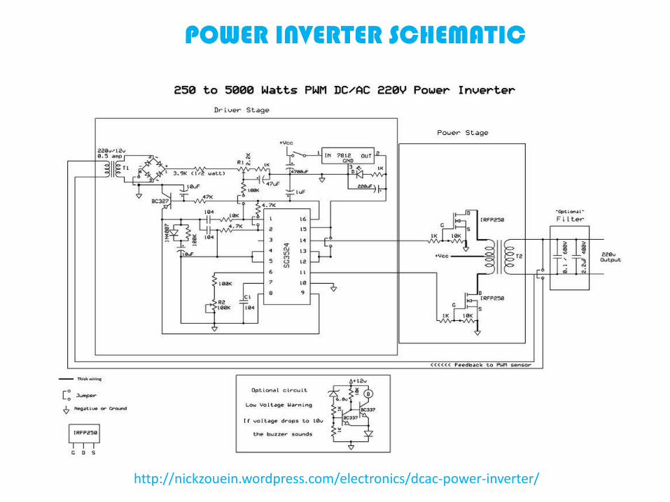
POWER INVERTER SCHEMATIC
http://nickzouein.wordpress.com/electronics/dcac-power-inverter/
Pros & Cons
• Cheaper, since it is home built.
• Schematic is hard to understand.
• Soldering and testing components onto board is time consuming.
• Current design needs to be downscale or upscale to meet the projects' initial conditions.
POWER INVERTER
FLYWHEEL ENERGY STORAGE (FES)
What is a FES?
• A device which consist of accelerating a rotor to a very high speed andmaintaining the energy in the system as rotational energy.
• The device can be accelerated or decelerated by adding or subtractingenergy from it.
• Most FES use electricity to accelerate and decelerate the flywheel.
• Energy density depends on two factors: the rotor geometry, and theproperty of the materials used in manufacturing the device. For isotropicrotors the following formula can be used:
𝐸
𝑚= 𝐾(
𝜎
𝜌), where E is the Kinetic energy, m the rotor’s mass, K the
rotor’s geometric shape factor, 𝜎 the tensile strength of the
material, and 𝜌 the material’s density.
http://en.wikipedia.org/wiki/Flywheel_energy_storage
FLYWHEEL ENERGY STORAGE (FES)
What is a FES?
• Materials with high strength, and low density are desirable. The use ofcarbon composite is recommended due to these properties and to its lowcost.
• When the tensile strength of the composite flywheel’s outer binding coveris exceeded, the binding cover will fracture, and the wheel will shatter atballistic speeds, therefore, the use of composite materials that are glued inlayers tend to disintegrate quickly into smaller diameter filaments withoutposing a higher risk to a person nearby.
• This design will incorporate a two pole rotor 3phase A-C generator, runningat 400HZ to achieve a maximum RPM of 24,000.
• A FES is a Dynamo that can run in a motor or in a generator configuration.
http://en.wikipedia.org/wiki/Flywheel_energy_storage

FES CUTOUT VIEWS
FES CUTOUT 2-D VIEW FES CUTOUT 3-D VIEW

FES CUTOUT ALTERNATE 3-D VIEW
NASA’S FLYWHEELThe National Aeronautics and Space Administration (NASA) is the United Statesgovernment agency that is responsible for the civilian space program as well as foraeronautics and aerospace research.

BEACON POWER FESBeacon Power is an American Limited Liability Company specializing in flywheel-based energy storage with headquartered in Tyngsborough, Massachusetts. Servingthe New York Area.


Pros & Cons
• Flywheel is very lightweight due to Carbon Fiber.
• Can charge and discharge within minutes.
• Not affected by temperature.
• Expensive to built.
• Current design needs to be downscale or upscale to meet the projects' initial conditions.
FLYWHEEL ENERGY STORAGE (FES)
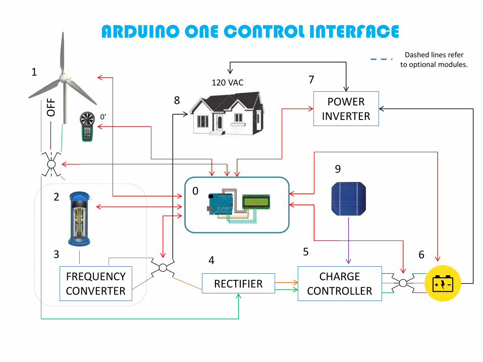
ARDUINO ONE CONTROL INTERFACE
Why choose this model?• Inexpensive @ $24 USD.
• Compatible with windows.
• Open source code.
• Easy interface.
• Programmable using C++.
ARDUINO ONE CONTROL INTERFACE
• The Control Interface will read and then display on aLCD the values for: the WPG torque, WPG speed,output voltage from WPG, output current from WPG,output power from WPG, charge stored in FES,output power from FES, angular velocity of FES,battery array charge levels, and total power output.
• The micro-controller will sound an alarm if thebattery stored power has depleted between 55% -50%.
• The micro-controller will control several switches:battery charging by FES, battery charging by WPG,battery charging by solar cells, disconnecting theWPG from all other modules during excess windconditions, and direct house feed; between the FESand the home.
ARDUINO ONE CONTROL INTERFACE
FREQUENCY CONVERTER
120 VAC
RECTIFIER
POWER INVERTER
CHARGE CONTROLLER
1
8
0
45
9
7
63
2
OFF
Dashed lines refer to optional modules.
0’
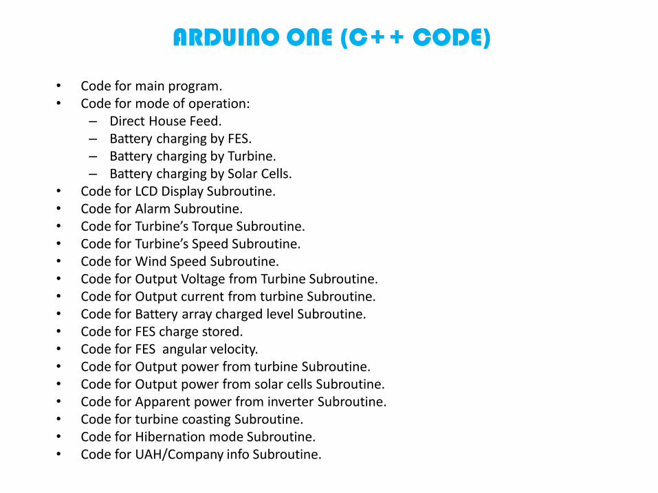
ARDUINO ONE (C++ CODE)
• Code for main program.• Code for mode of operation:
– Direct House Feed.– Battery charging by FES.– Battery charging by Turbine.– Battery charging by Solar Cells.
• Code for LCD Display Subroutine.• Code for Alarm Subroutine.• Code for Turbine’s Torque Subroutine.• Code for Turbine’s Speed Subroutine.• Code for Wind Speed Subroutine.• Code for Output Voltage from Turbine Subroutine.• Code for Output current from turbine Subroutine.• Code for Battery array charged level Subroutine.• Code for FES charge stored.• Code for FES angular velocity.• Code for Output power from turbine Subroutine.• Code for Output power from solar cells Subroutine.• Code for Apparent power from inverter Subroutine.• Code for turbine coasting Subroutine.• Code for Hibernation mode Subroutine.• Code for UAH/Company info Subroutine.

ARDUINO ONE CONTROL INTERFACE
Circuit Schematic for Arduino One

CONCLUSION
PROS
• Advantages are low pollution level to the environment, maintainable onceevery 5 years for FES and once every 3 years for batteries.
• For FES, device is enclose completely in vacuum, and magneticallylevitated, that means no drag for the rotor.
• For WPG, device is magnetically levitated, that means no friction in thebearings between rotor and stator.
• Long Lifetime for FES.• FES Unaffected by ambient temperatures extremes.• FES operation at < 24,000 rpm.• FES can fully charge within seconds.• GMAG-WINDSOPTSS can provide auxiliary power for a residential home in
case of a grid shutdown or simply to lower a household’s electric bill.

CONCLUSION
CONS
• Due to time constrains and funding, only theoretical design of FES will be covered.• FES Expensive and hard to manufacture. Cheapest way is using a carbon composite
disc.• FES can only provide power for minutes, therefore FES tends to discharge faster than
batteries.• If FES device reaches a very high speed, the carbon composite disc attached to one
end of the rotor will disintegrate violently due to centrifugal forces.• FES Device needs to be reinforce with thick steel for human protection against
explosions.• Chemical Batteries uses lead.• Chemical Batteries are affected by temperature changes.• Solar Panels are affected by accumulation of dust, snow, and depend on weather
conditions to be optimal for sunshine.• Modules had to be assembled.• Batteries and solar cells had to be ordered from overseas adding a high cost to
shipping.

CONCLUSION
Questions and answers session.
www.linkedin.com/pub/jürgen-andrés-sawatzki-chaw/87/979/262/


