Embed Size (px)
Citation preview
SUBJECT CODE : EE6702
SUBJECT NAME: Protection & switchgear
STAFF NAME : Ms.J.C.Vinitha
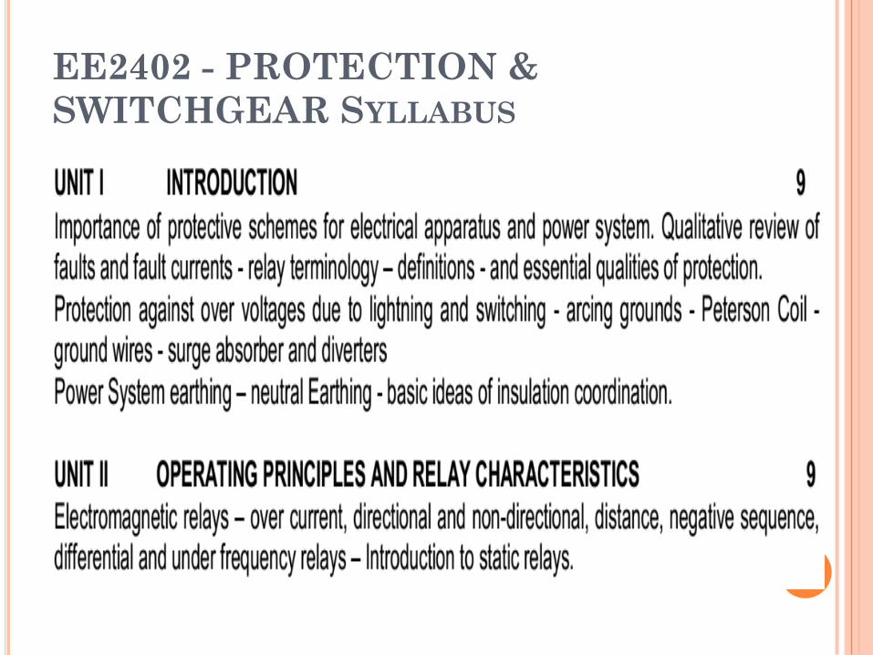
EE2402 - PROTECTION &
SWITCHGEAR SYLLABUS
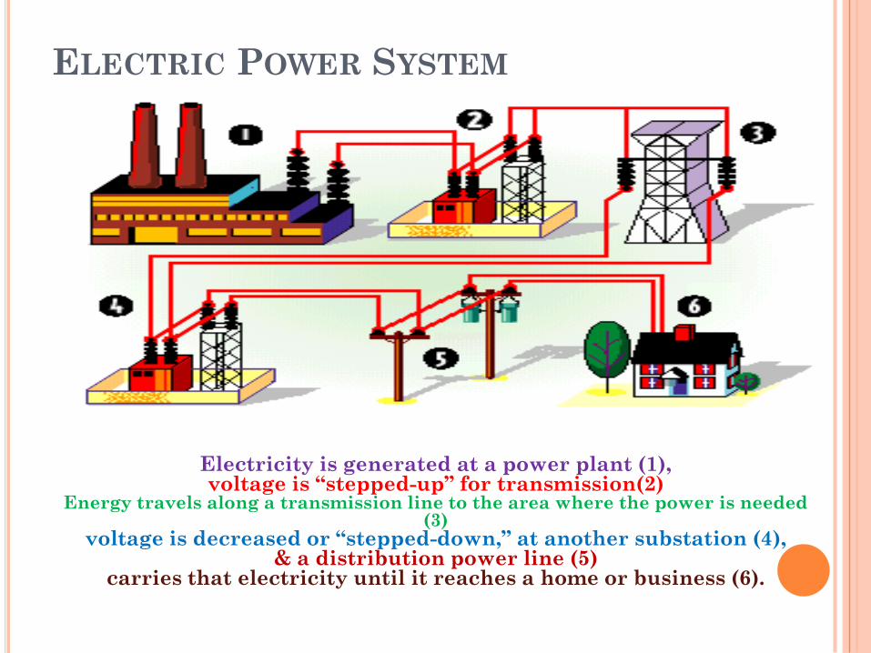
ELECTRIC POWER SYSTEM
Electricity is generated at a power plant (1), voltage is “stepped-up” for transmission(2)
Energy travels along a transmission line to the area where the power is needed (3)
voltage is decreased or “stepped-down,” at another substation (4),& a distribution power line (5)
carries that electricity until it reaches a home or business (6).
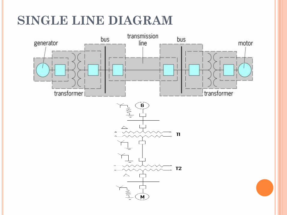
SINGLE LINE DIAGRAM
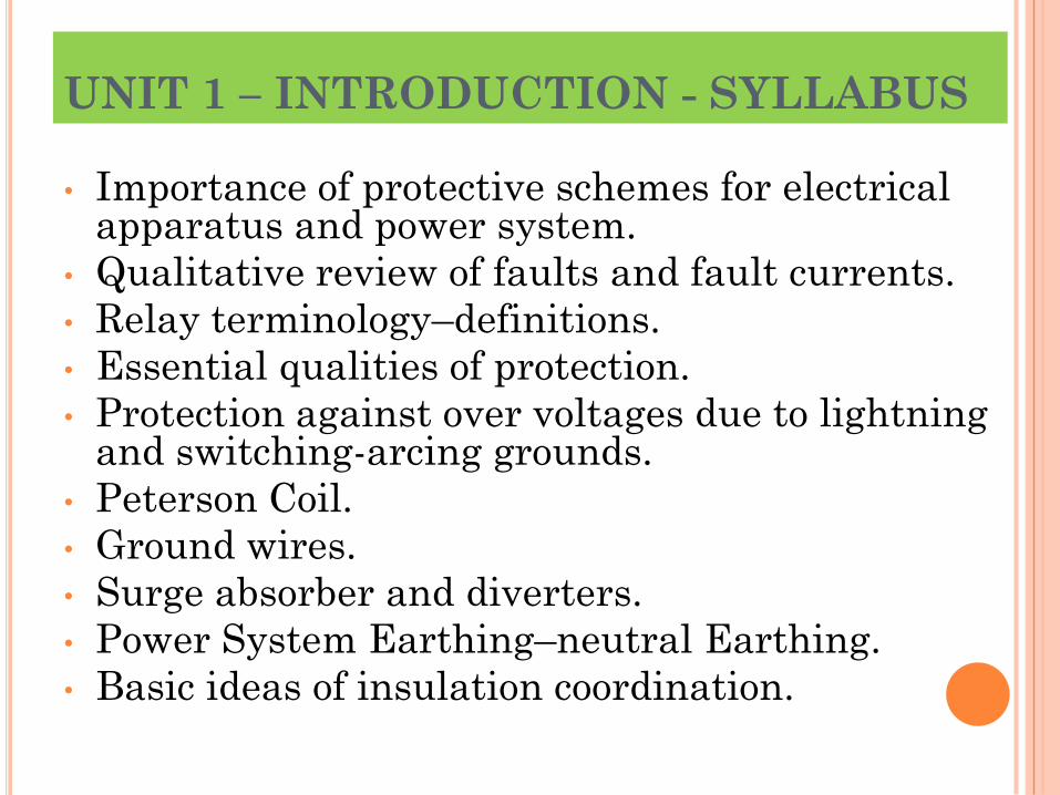
UNIT 1 – INTRODUCTION - SYLLABUS
• Importance of protective schemes for electrical apparatus and power system.
• Qualitative review of faults and fault currents.
• Relay terminology–definitions.
• Essential qualities of protection.
• Protection against over voltages due to lightning and switching-arcing grounds.
• Peterson Coil.
• Ground wires.
• Surge absorber and diverters.
• Power System Earthing–neutral Earthing.
• Basic ideas of insulation coordination.
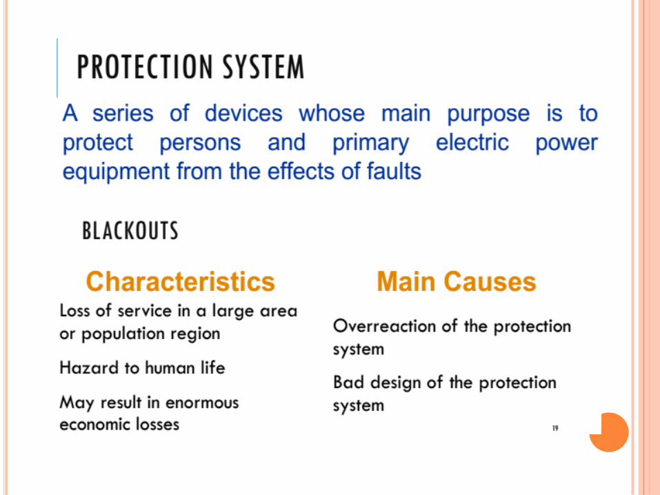
IMPORTANCE OF
PROTECTIVE SCHEMES FOR
ELECTRICAL APPARATUS
AND POWER SYSTEM
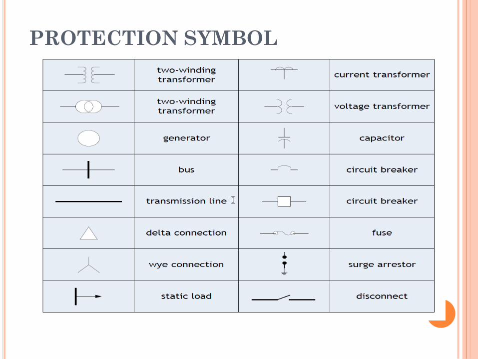
PROTECTION SYMBOL
PRIMARY EQUIPMENT & COMPONENTS
• Transformers-to step up or step down voltage level.
• Breakers-to energize equipment and interrupt fault
current to isolate faulted equipment.
• Insulators-to insulate equipment from ground and
other phases.
• Isolators (switches) -to create a visible and
permanent isolation of primary equipment for
maintenance purposes and route power flow over
certain buses.
• Bus-to allow multiple connections (feeders) to the
same source of power (transformer).
PRIMARY EQUIPMENT & COMPONENTS
• Grounding-to operate and maintain equipment safely
• Arrester-to protect primary equipment of sudden
overvoltage (lightning strike).
• Switchgear–integrated components to switch,
protect, meter and control power flow.
• Reactors-to limit fault current (series) or compensate
for charge current (shunt).
• VT and CT -to measure primary current and voltage
and supply scaled down values to P&C, metering,
SCADA, etc.
• Regulators-voltage, current, VAR, phase angle, etc.
WHY A SYSTEM NEEDS PROTECTION?
There is no „fault free‟ system.
Ensure safety of personnel.
Usually faults are caused by breakdown of insulation due to various reasons : system over current, over voltage, lighting etc.
POWER SYSTEM WITHOUT
PROTECTION
Short circuits and other
abnormal conditions often
occur on the power system.
The heavy current associated
with short circuits is likely to
cause damage to the
equipment.
ELEMENT OF PROTECTION
SYSTEM
(1) Current and Voltage
Transformers.
(2) Relays.
(3) Circuit breakers.
(4) Batteries.
(5) Fuses.
(6) Lighting Arresters.
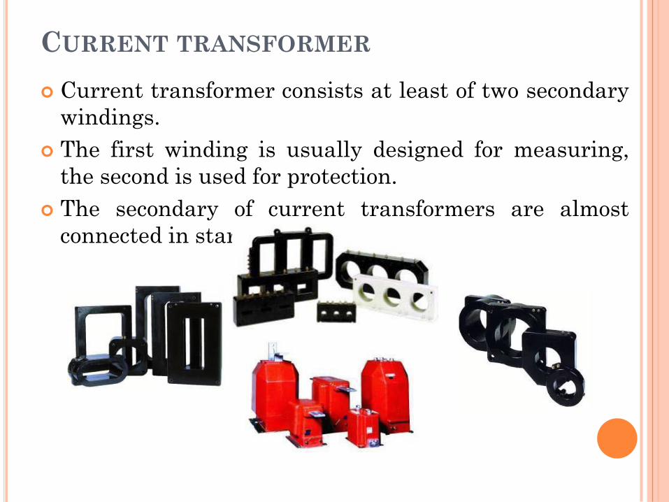
CURRENT TRANSFORMER
Current transformer consists at least of two secondary
windings.
The first winding is usually designed for measuring,
the second is used for protection.
The secondary of current transformers are almost
connected in star
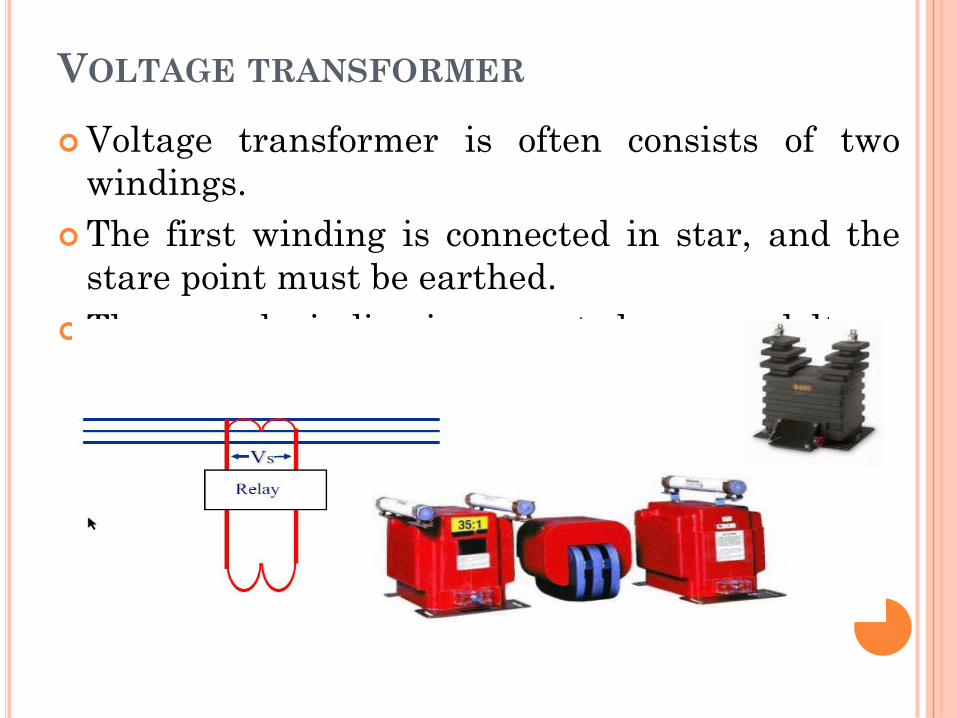
VOLTAGE TRANSFORMER
Voltage transformer is often consists of two
windings.
The first winding is connected in star, and the
stare point must be earthed.
The second winding is connected as open delta.
PURPOSE OF RELAY
• Isolate controlling circuit from
controlled circuit.
• Control high voltage system
with low voltage.
• Control high current system
with low current.
• Logic Functions
ADVANTAGES FOR USING PROTECTIVE
RELAYS
Detect system failures whenthey occur and isolate thefaulted section from theremaining of the system.
Mitigating the effects of failuresafter they occur.
Minimize risk of fire, danger topersonal and other high voltagesystems.
CIRCUIT BREAKER
Low voltage circuit breaker.
Magnetic circuit breaker.
Medium voltage circuit breaker.
High voltage circuit breaker.
BATTERY BANK
• Battery bank are called as
backbone of protection
system.
• Emergency use for power
system.
FUSE
• Fuses are selected to allowpassage of normal currentand of excessive current onlyfor short periods.
• It is used to protect the low voltage or current rating devices.
LIGHTING ARRESTER
A lightning arrester is adevice used on electricalpower system to protect theinsulation damaging effect oflightning.
All lighting arrester are earthed.
WHAT IS SWITCHGEAR ?
• Switchgear is the
combination of switches,
fuses or circuit breakers(CB)
used to control, protect &
isolate electrical equipment.
• It is used de-energize
equipment & clear faults.
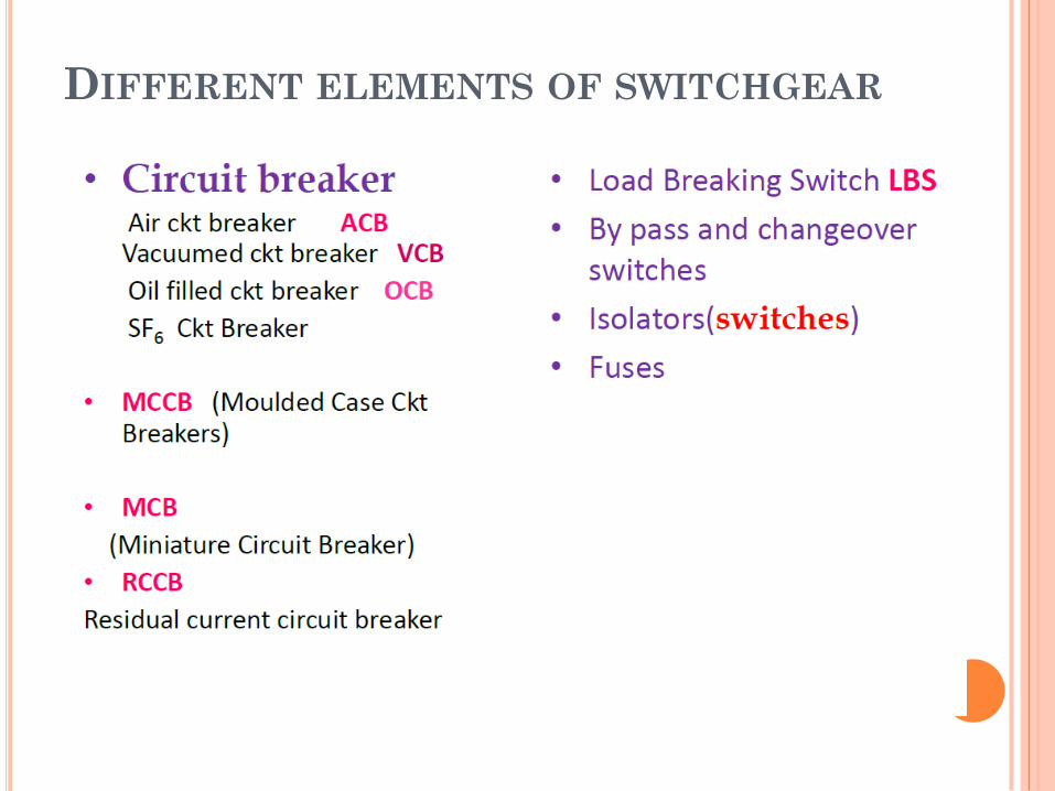
DIFFERENT ELEMENTS OF SWITCHGEAR
FUNCTION WISE CATEGORIES
• Automatic & Manual operation
{ example: Circuit breaker ,MCB ,
MCCB }
• Only automatic operation
Fuse
• Only manually activated / operated
Isolator, LBS
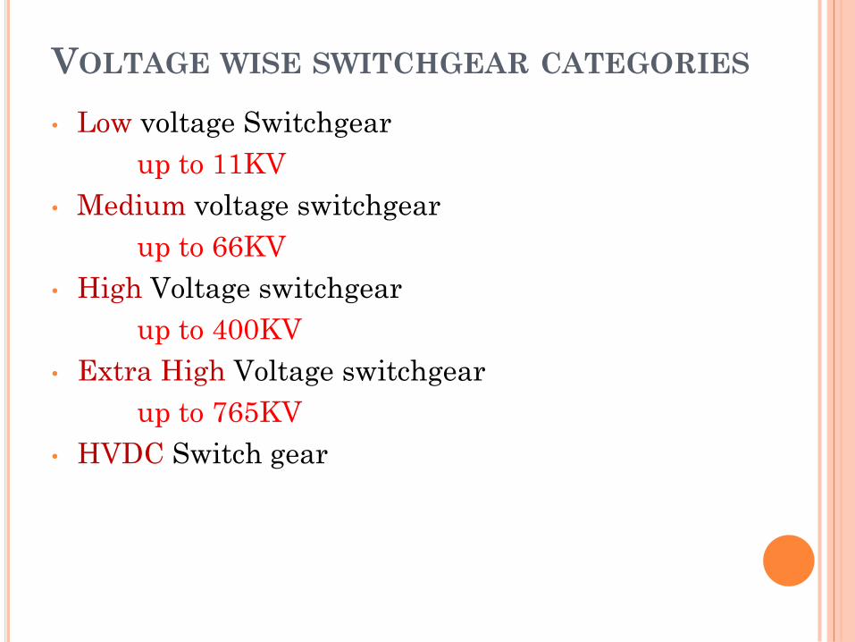
VOLTAGE WISE SWITCHGEAR CATEGORIES
• Low voltage Switchgear
up to 11KV
• Medium voltage switchgear
up to 66KV
• High Voltage switchgear
up to 400KV
• Extra High Voltage switchgear
up to 765KV
• HVDC Switch gear
QUALITATIVE
REVIEW OF FAULTS
& FAULT CURRENTS
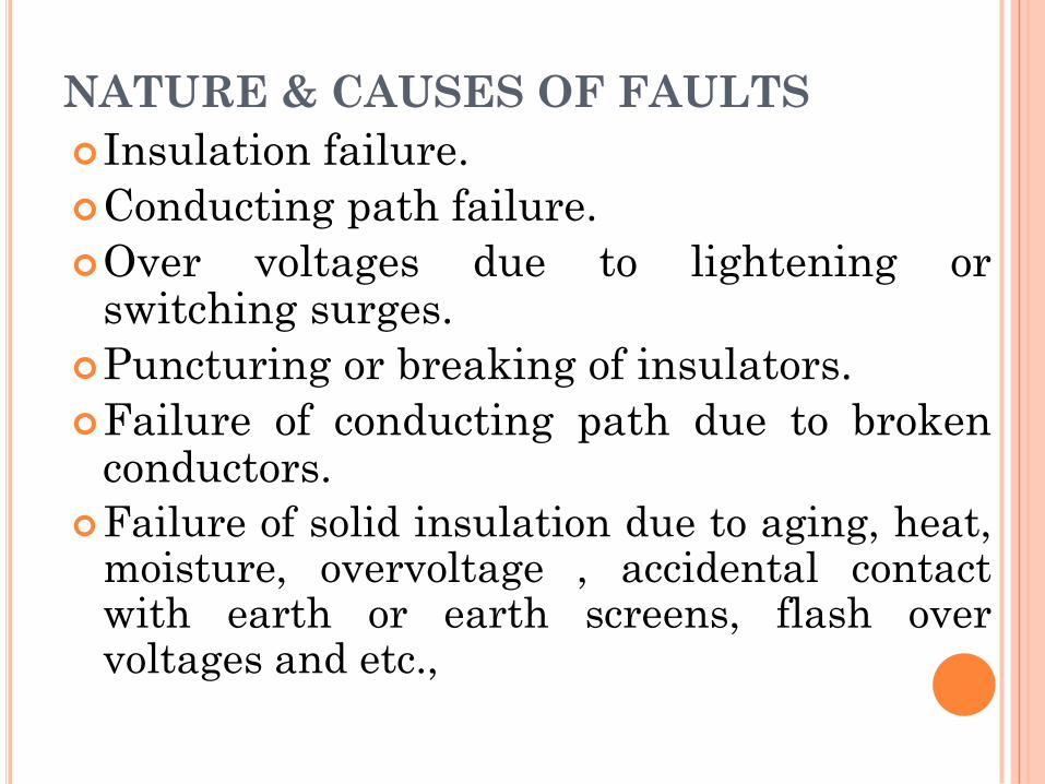
NATURE & CAUSES OF FAULTS
Insulation failure.
Conducting path failure.
Over voltages due to lightening orswitching surges.
Puncturing or breaking of insulators.
Failure of conducting path due to brokenconductors.
Failure of solid insulation due to aging, heat,moisture, overvoltage , accidental contactwith earth or earth screens, flash overvoltages and etc.,
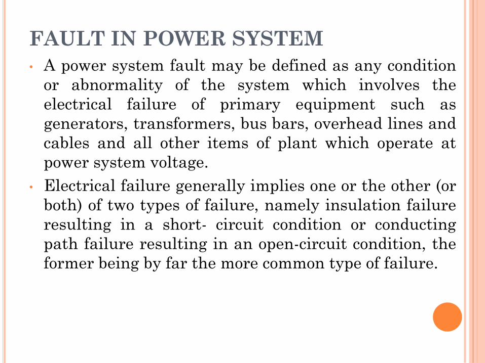
FAULT IN POWER SYSTEM
• A power system fault may be defined as any condition
or abnormality of the system which involves the
electrical failure of primary equipment such as
generators, transformers, bus bars, overhead lines and
cables and all other items of plant which operate at
power system voltage.
• Electrical failure generally implies one or the other (or
both) of two types of failure, namely insulation failure
resulting in a short- circuit condition or conducting
path failure resulting in an open-circuit condition, the
former being by far the more common type of failure.
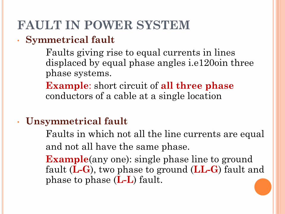
FAULT IN POWER SYSTEM• Symmetrical fault
Faults giving rise to equal currents in lines displaced by equal phase angles i.e120oin three phase systems.
Example: short circuit of all three phase conductors of a cable at a single location
• Unsymmetrical fault
Faults in which not all the line currents are equal
and not all have the same phase.
Example(any one): single phase line to ground fault (L-G), two phase to ground (LL-G) fault and phase to phase (L-L) fault.
ABNORMALITIES IN POWER SYSTEMS
• Overcurrent (overload, short circuit, open circuit)
• Ground Potential (ungrounded equipment, touch
potentials, step potentials)
• Surge Voltages (lightning strokes, switching
surges, harmonics)
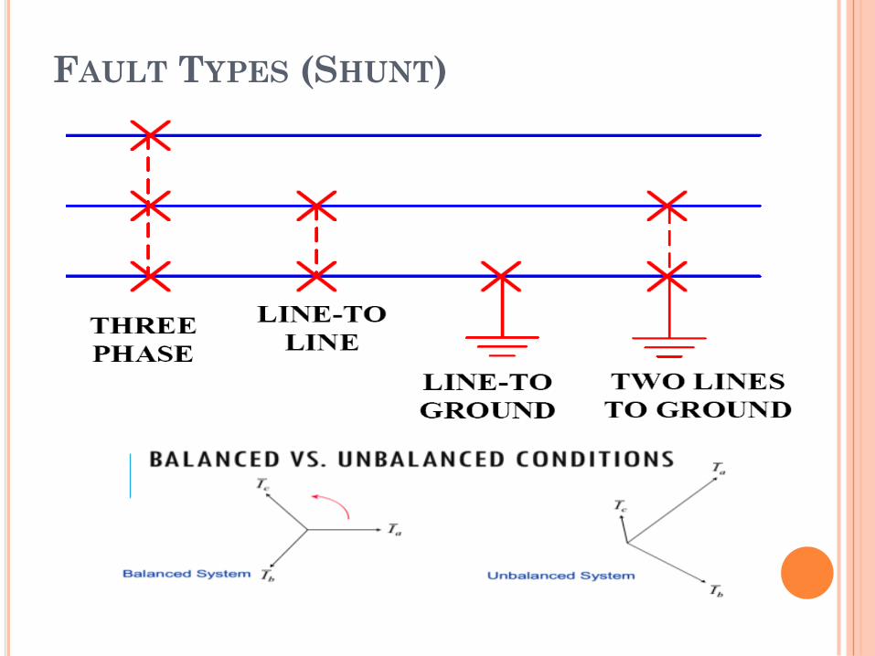
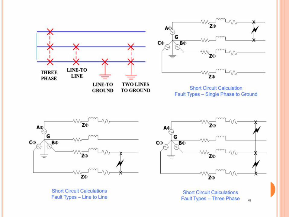
FAULT TYPES (SHUNT)
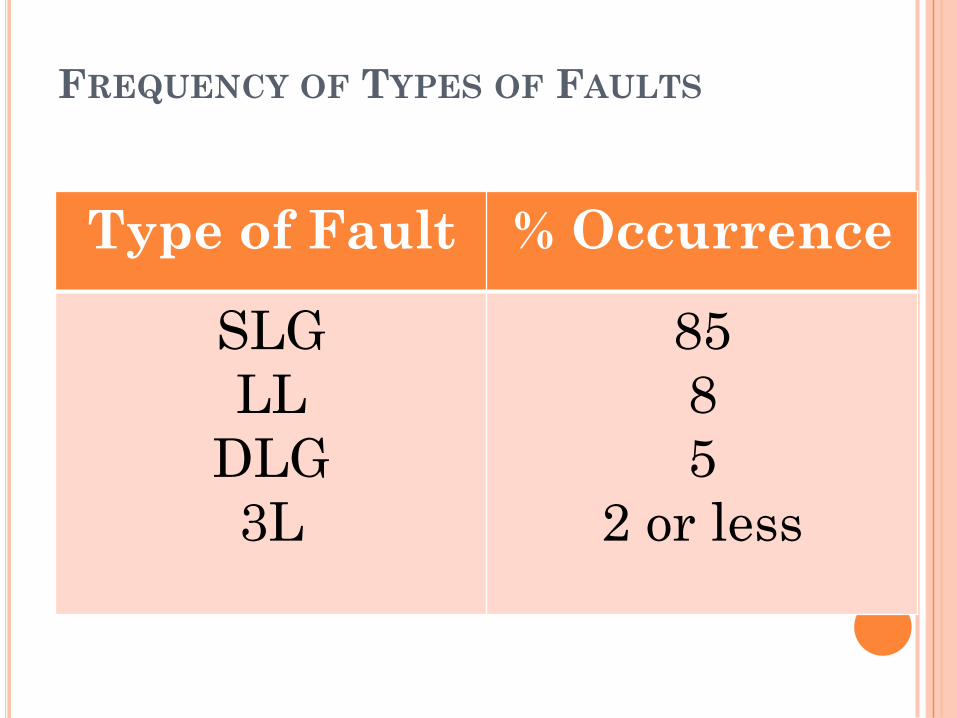
FREQUENCY OF TYPES OF FAULTS
Type of Fault % Occurrence
SLG
LL
DLG
3L
85
8
5
2 or less
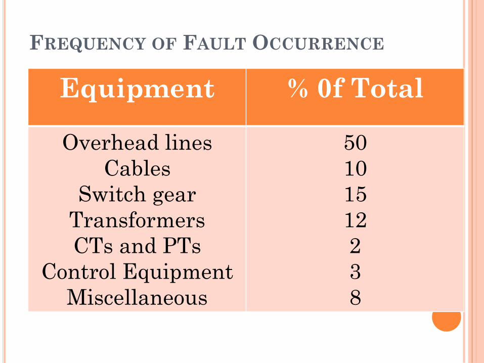
FREQUENCY OF FAULT OCCURRENCE
Equipment % 0f Total
Overhead lines
Cables
Switch gear
Transformers
CTs and PTs
Control Equipment
Miscellaneous
50
10
15
12
2
3
8
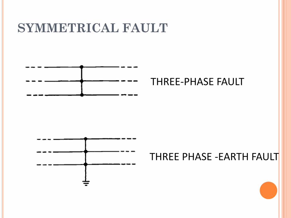
SYMMETRICAL FAULT
THREE-PHASE FAULT
THREE PHASE -EARTH FAULT
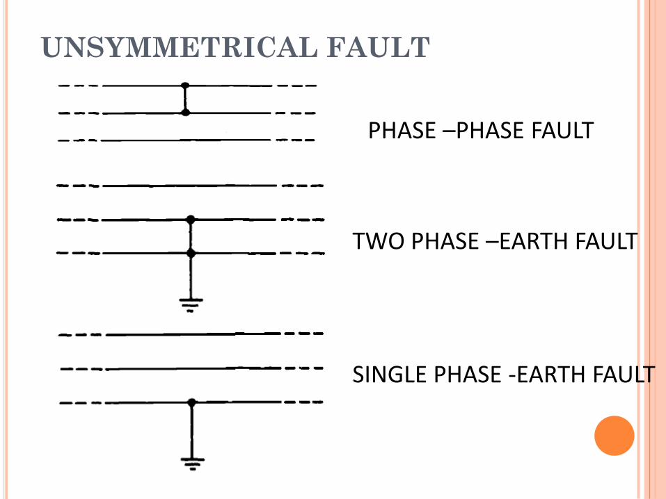
UNSYMMETRICAL FAULT
PHASE –PHASE FAULT
TWO PHASE –EARTH FAULT
SINGLE PHASE -EARTH FAULT
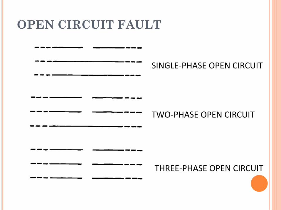
OPEN CIRCUIT FAULT
SINGLE-PHASE OPEN CIRCUIT
TWO-PHASE OPEN CIRCUIT
THREE-PHASE OPEN CIRCUIT
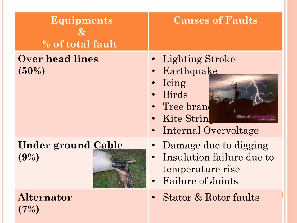
Equipments
&
% of total fault
Causes of Faults
Over head lines
(50%)
• Lighting Stroke
• Earthquake
• Icing
• Birds
• Tree branches
• Kite Strings
• Internal Overvoltage
Under ground Cable
(9%)
• Damage due to digging
• Insulation failure due to
temperature rise
• Failure of Joints
Alternator
(7%)
• Stator & Rotor faults
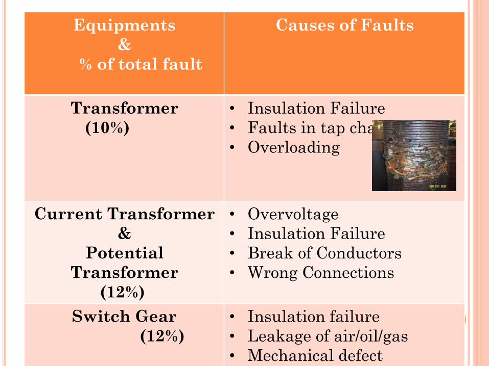
Equipments
&
% of total fault
Causes of Faults
Transformer
(10%)
• Insulation Failure
• Faults in tap changer
• Overloading
Current Transformer
&
Potential
Transformer
(12%)
• Overvoltage
• Insulation Failure
• Break of Conductors
• Wrong Connections
Switch Gear
(12%)
• Insulation failure
• Leakage of air/oil/gas
• Mechanical defect
• Lack of Maintenance
FAULT MINIMIZATION
Improving the quality of machines,
equipments, installation etc., by
improving the design techniques.
Adequate & reliable protection
system control.
Regular maintenance by trained
professionals.
Effective management of electrical
plant.
MERITS OF FAST FAULT CLEARING
Helps to avoid permanent damage
to equipment & components of
the apparatus.
Reduces the chances of risks like
fire hazards.
Maintains the continuity of the
power supply.
Brings back the power system to the
normal state sooner.
RELAY TERMINOLOGY –
DEFINITIONS
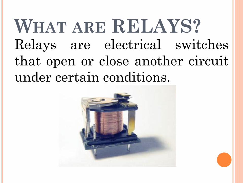
WHAT ARE RELAYS?Relays are electrical switches
that open or close another circuit
under certain conditions.
WHAT IS A PROTECTIVE
RELAY?
Protective relays are devices
which monitor power system
conditions and operate to quickly
and accurately isolate faults or
dangerous conditions. A well
designed protective system can limit
damage to equipment, as well as
minimize the extent of associated
service interruption.
RELAY PURPOSE
Isolate controlling circuit from
controlled circuit.
Control high voltage system
with low voltage.
Control high current system
with low current.
Logic Functions.
RELAY TYPES
• Electromagnetic Relays (EMRs)
• Solid-state Relays (SSRs)
There is no mechanical contacts to switch
the circuit.
• Microprocessor Based Relays
Commonly used in power system
monitoring and protection.
ADVANTAGES /
DISADVANTAGES• Electromagnetic Relays (EMRs)
– Simplicity
– Not expensive
• Solid-state Relays (SSRs)– No Mechanical movements
– Faster than EMR
• Microprocessor-based Relay– Much higher precision and more reliable and durable.
– Capable of both digital and analog I/O.
– Higher cost
ADVANTAGES FOR USING
PROTECTIVE RELAYS
Detect system failures when they
occur and isolate the faulted section
from the remaining of the system.
Mitigating the effects of failures
after they occur. Minimize risk of
fire, danger to personal and other
high voltage systems.
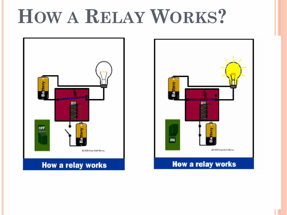
HOW A RELAY WORKS?
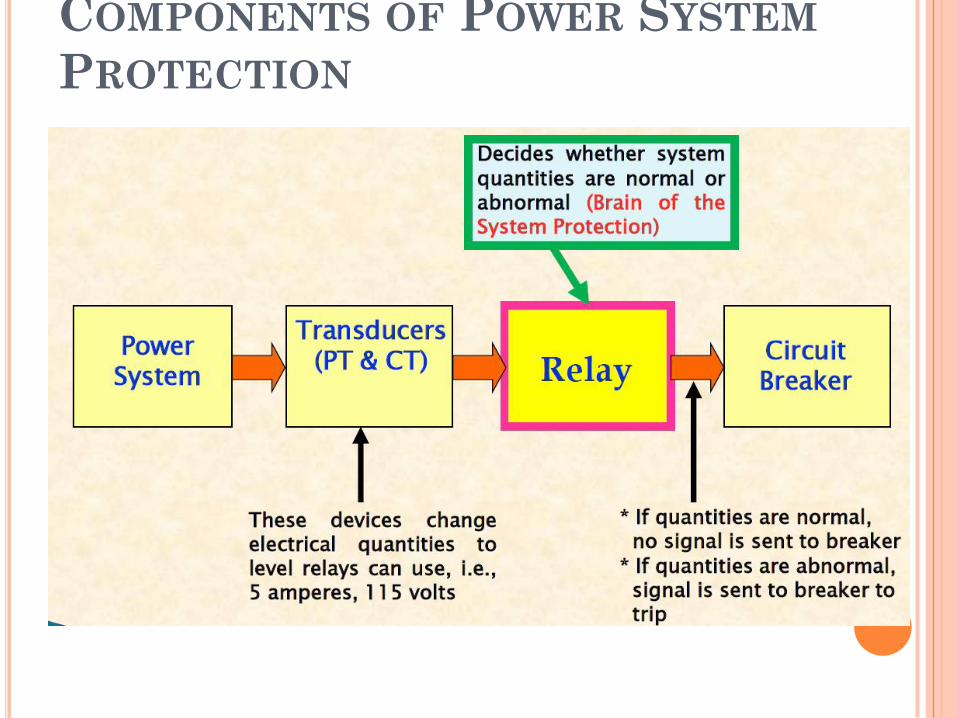
COMPONENTS OF POWER SYSTEM
PROTECTION
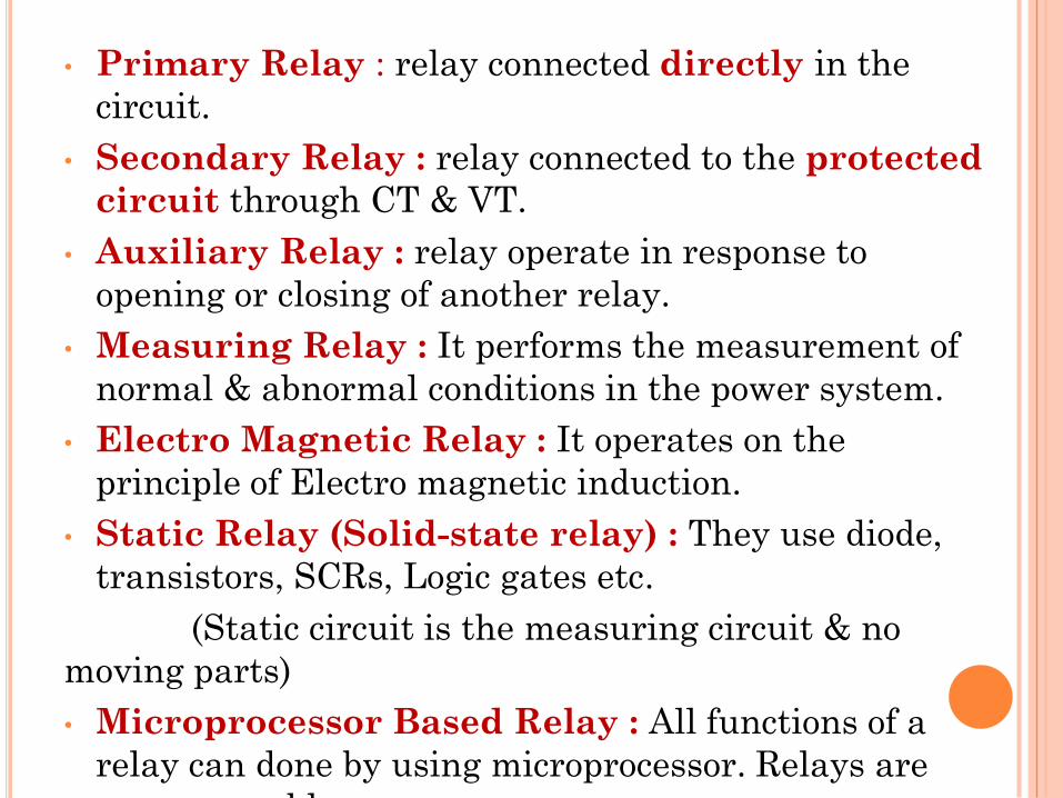
• Primary Relay : relay connected directly in the
circuit.
• Secondary Relay : relay connected to the protected
circuit through CT & VT.
• Auxiliary Relay : relay operate in response to
opening or closing of another relay.
• Measuring Relay : It performs the measurement of
normal & abnormal conditions in the power system.
• Electro Magnetic Relay : It operates on the
principle of Electro magnetic induction.
• Static Relay (Solid-state relay) : They use diode,
transistors, SCRs, Logic gates etc.
(Static circuit is the measuring circuit & no
moving parts)
• Microprocessor Based Relay : All functions of a
relay can done by using microprocessor. Relays are
programmable.
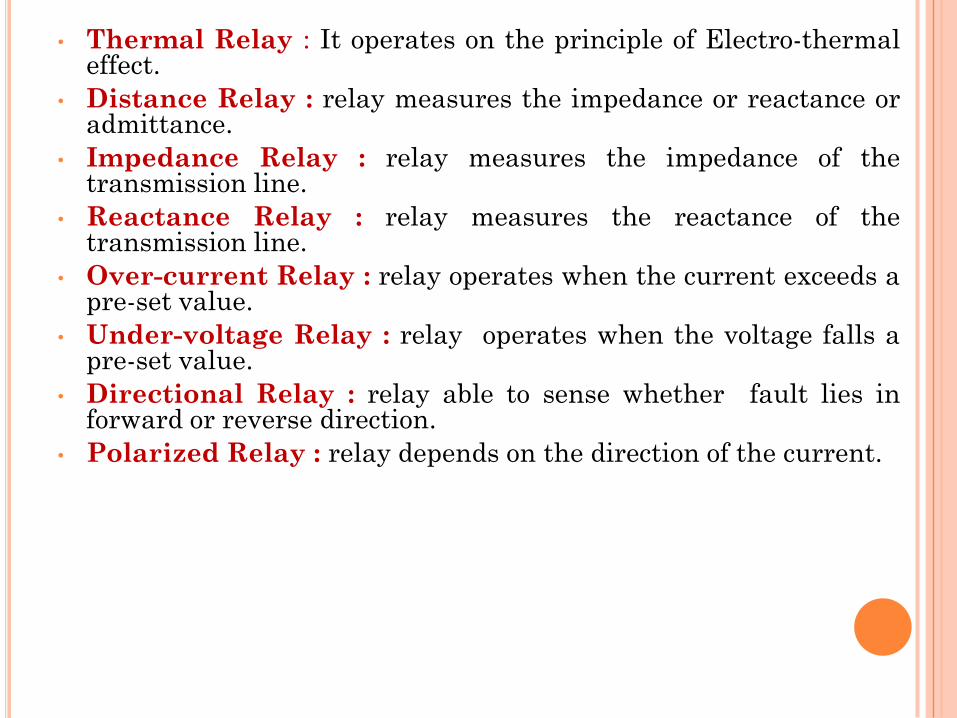
• Thermal Relay : It operates on the principle of Electro-thermaleffect.
• Distance Relay : relay measures the impedance or reactance oradmittance.
• Impedance Relay : relay measures the impedance of thetransmission line.
• Reactance Relay : relay measures the reactance of thetransmission line.
• Over-current Relay : relay operates when the current exceeds apre-set value.
• Under-voltage Relay : relay operates when the voltage falls apre-set value.
• Directional Relay : relay able to sense whether fault lies inforward or reverse direction.
• Polarized Relay : relay depends on the direction of the current.
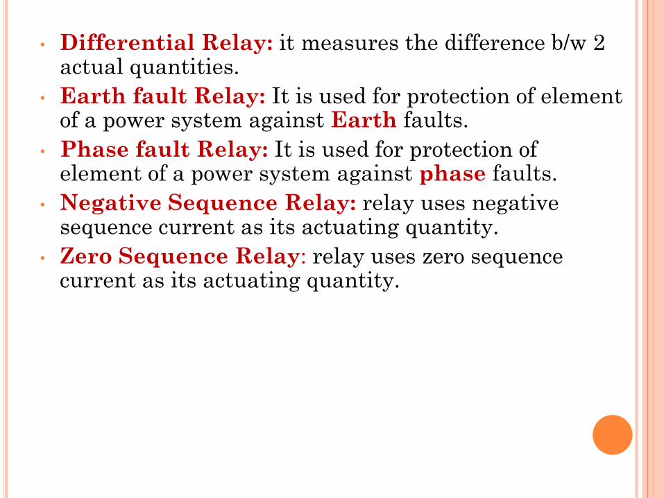
• Differential Relay: it measures the difference b/w 2 actual quantities.
• Earth fault Relay: It is used for protection of element of a power system against Earth faults.
• Phase fault Relay: It is used for protection of element of a power system against phase faults.
• Negative Sequence Relay: relay uses negative sequence current as its actuating quantity.
• Zero Sequence Relay: relay uses zero sequence current as its actuating quantity.
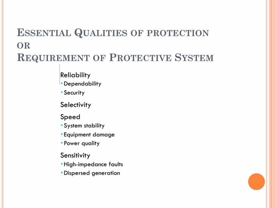
ESSENTIAL QUALITIES OF PROTECTION
OR
REQUIREMENT OF PROTECTIVE SYSTEM
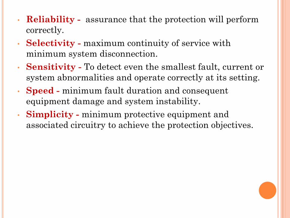
• Reliability - assurance that the protection will perform
correctly.
• Selectivity - maximum continuity of service with
minimum system disconnection.
• Sensitivity - To detect even the smallest fault, current or
system abnormalities and operate correctly at its setting.
• Speed - minimum fault duration and consequent
equipment damage and system instability.
• Simplicity - minimum protective equipment and
associated circuitry to achieve the protection objectives.
• Reliability
oThe level of assurance that the relay will function as intended.
oReliability denotes : – Dependability-certainty of correct operation
– Security-assurance against incorrect operation
• Sensitivity
oRelaying equipment must be sufficiently sensitive so that it will operate when required
oMust discriminate normal from abnormal conditions.
• Selectivityo Performance of protective devices to select between those
conditions for which prompt operation and those for which nooperation, or time delay operation is required.
o Isolate faulted circuit resulting in minimum interruptions.
o Implemented through “Zone of Protection”
• Speedo Remove a fault from the power system as quickly as possible
o Classification:
– Instantaneous -no intentional delay
– High Speed -less than 3 cycles
– Time-Delay -intentional time delay
POWER SYSTEM
EARTHING
Neutral Earthing /Grounding
Peterson coil
Arcing Grounds
EARTHING / GROUNDING
• The process of connecting the metallic frame (i.e.
non-current carrying part) of electrical equipment or
some electrical part of the system to earth (i.e. soil)
is called grounding or earthing.
• Grounding or earthing may be classified as:
(i) Equipment grounding
(ii) System grounding
GROUNDING TYPES
• Equipment Grounding
The process of connecting non-
current-carrying metal parts of the
electrical equipment to earth.
• System Grounding
The process of connecting some
electrical part of the power system to
earth (i.e.soil) is called system
grounding.

NEUTRAL EARTHING
NEUTRAL GROUNDING
• Connecting neutral point to earth (i.e.soil) either
directly or some circuit element
(e.g.resistance, reactance, Peterson coil etc.)
is called neutral grounding.
• Neutral grounding provides protection to equipment.
(during earth fault, the current path is completed
neutral)
ADVANTAGES OF NEUTRAL GROUNDING
(i) Voltages of the healthy phases do not exceed line to groundvoltages i.e. they remain nearly constant.
(ii) The high voltages due to arcing grounds are eliminated.
(iii) Life of insulation is long.
(iv) The over voltages is reduced.
(v) It provides greater safety to personnel and equipment.
(vi) It provides improved service reliability.
(vii) Operating and maintenance expenditures are reduced.
METHODS OF NEUTRAL GROUNDING
1. Solid or effective grounding
2. Resistance grounding
3. Reactance grounding
4. Peterson-coil grounding
5. Voltage transformer earthing
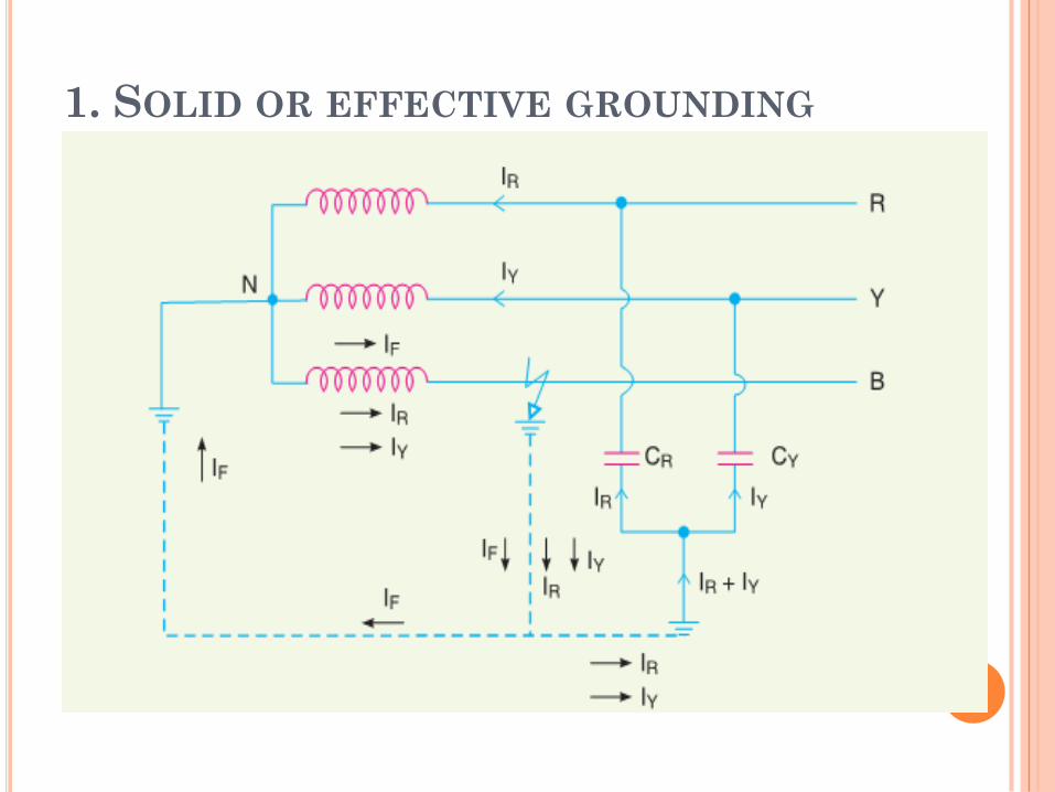
1. SOLID OR EFFECTIVE GROUNDING
1. SOLID OR EFFECTIVE GROUNDING
• When the neutral point of a 3-phase system is directly connected to earth(i.e. soil) is called solid grounding or effective grounding.
• When an earth fault occurs between earth and any one phase , the voltage to earth of the faulty phase becomes zero, but the healthy phases remains at normal phase values.
• Fault current(IF) completely nullified by capacitive current(IC)
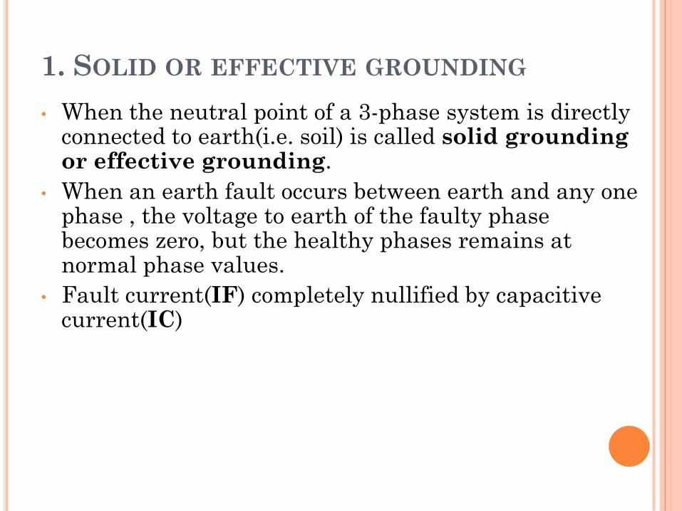
2. RESISTANCE GROUNDING
When the neutral point of a 3-phase system(e.g. 3-phase generator, 3-phase transformeretc.) is connected to earth ( i.e. soil) througha resistor, it is called resistance grounding.
2. RESISTANCE GROUNDING
Advantages:
• By adjusting the value of R, the arcing grounds can be minimized.
• It improves the stability.
• Less interference.
• Minimize hazards.
Disadvantages:
• By adjusting the value of R, the arcing grounds can be minimized.
• It improves the stability.
• Less interference.
• Minimize hazards.
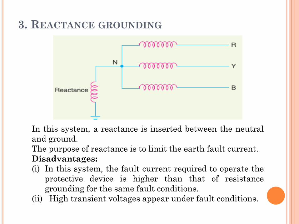
3. REACTANCE GROUNDING
In this system, a reactance is inserted between the neutral
and ground.
The purpose of reactance is to limit the earth fault current.
Disadvantages:
(i) In this system, the fault current required to operate the
protective device is higher than that of resistance
grounding for the same fault conditions.
(ii) High transient voltages appear under fault conditions.
4. PETERSON COIL
(OR)
ARC SUSPENSION COIL
GROUNDING
(OR)
RESONANT GROUNDING
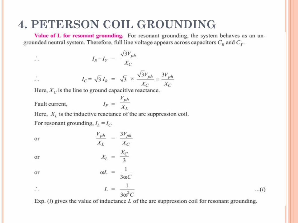
4. PETERSON COIL GROUNDINGIf inductance L of appropriate value is connected in
parallel with the capacitance of the system, the fault currentIF flowing through L will be in phase opposition to thecapacitive current IC of the system. If L is so adjusted that
IL = IC
then resultant current in the fault will be zero. Thiscondition is known as Resonant Grounding.
When the value of L of arc suppression coil is suchthat the fault current IF exactly balances the capacitivecurrent IC, it is called Resonant Grounding.
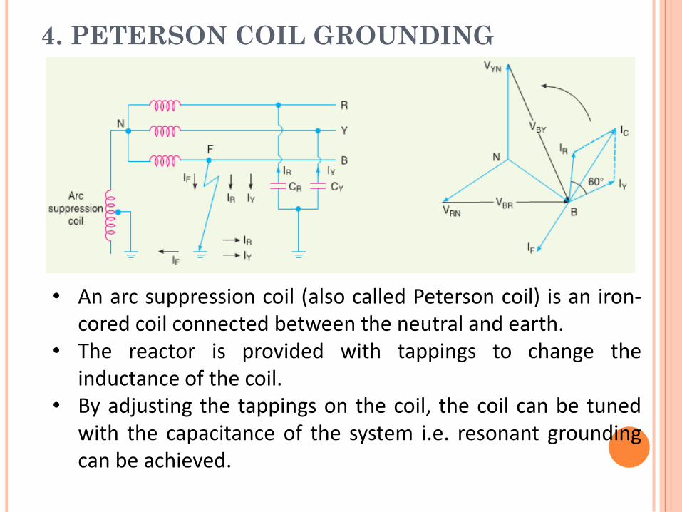
4. PETERSON COIL GROUNDING
• An arc suppression coil (also called Peterson coil) is an iron-cored coil connected between the neutral and earth.
• The reactor is provided with tappings to change theinductance of the coil.
• By adjusting the tappings on the coil, the coil can be tunedwith the capacitance of the system i.e. resonant groundingcan be achieved.
4. PETERSON COIL GROUNDING
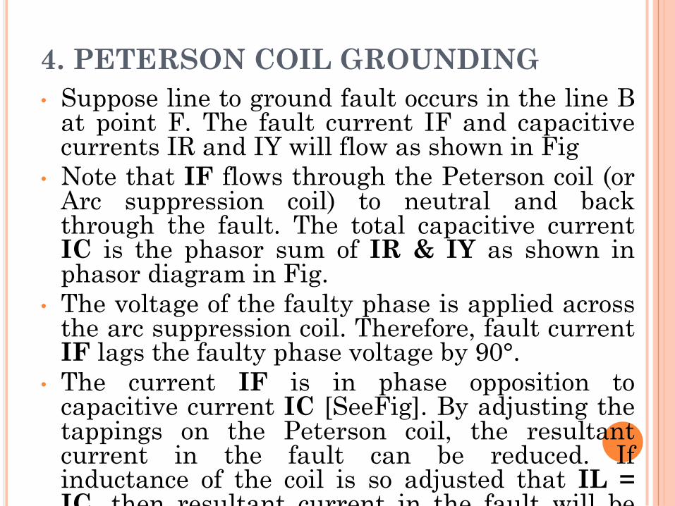
• Suppose line to ground fault occurs in the line Bat point F. The fault current IF and capacitivecurrents IR and IY will flow as shown in Fig
• Note that IF flows through the Peterson coil (orArc suppression coil) to neutral and backthrough the fault. The total capacitive currentIC is the phasor sum of IR & IY as shown inphasor diagram in Fig.
• The voltage of the faulty phase is applied acrossthe arc suppression coil. Therefore, fault currentIF lags the faulty phase voltage by 90°.
• The current IF is in phase opposition tocapacitive current IC [SeeFig]. By adjusting thetappings on the Peterson coil, the resultantcurrent in the fault can be reduced. Ifinductance of the coil is so adjusted that IL =IC, then resultant current in the fault will bezero.
4. PETERSON COIL GROUNDING
4. PETERSON COIL GROUNDING
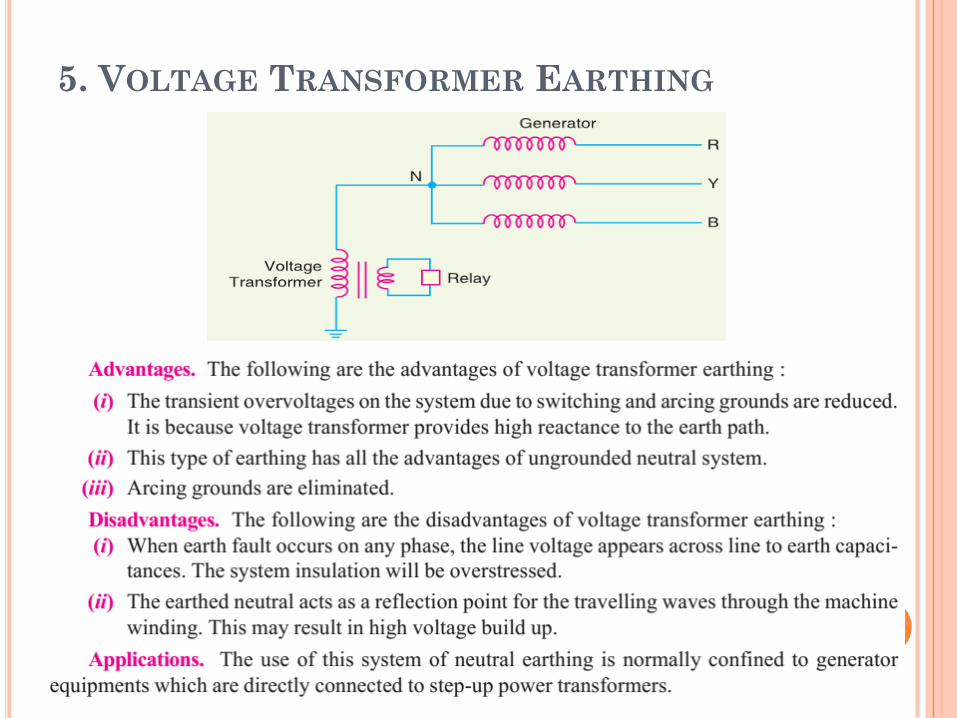
5. VOLTAGE TRANSFORMER EARTHING
In this method of neutral earthing, the primary of a
single-phase voltage transformer is connected between
the neutral and the earth as shown in Fig
A low resistor in series with a relay is connected across
the secondary of the voltage transformer. The voltage
transformer provides a high reactance in the neutral
earthing circuit and operates virtually as an
ungrounded neutral system.
5. VOLTAGE TRANSFORMER EARTHING
PROTECTION AGAINST
OVER VOLTAGES DUE
TO LIGHTNING AND
SWITCHING
PROTECTION AGAINST OVER VOLTAGES DUE
TO LIGHTNING AND SWITCHING
• During Operation , PS equipments such as Generator,
transformer, Tx. lines may subject to Over Voltage.
• OV occurs due to Lightning, opening of CB & so on.
• Causes Of OV• Internal Cause
• External Cause
PROTECTION AGAINST OVER VOLTAGES DUE
TO LIGHTNING AND SWITCHING
External
– Lightning
– Tree falls on Tx.lines causes SC
Internal
– Insulation Failure
– Resonance
– Arching Ground
– Switching Surges
TYPES OF OVER VOLTAGES
Power Frequency OV
Switching OV
Lightning OV
1. POWER FREQUENCY OV
Does not have damaging effects like switching or
lightning surges
It will be harmful, if sustained for longer duration
Mainly due to
Ground faults
Sudden load rejection
Loose connection
2. SWITCHING OV
• Also known as Switching surge or over voltage transient.
• Sudden rise of voltage for a very short duration in PS network isknown as transient voltage or voltage surge.
• An electrical transient appears, if there is sudden change in the stateof energy in PS network. This sudden change is due to
i. Closing a Switch
ii. Opening a Switch
iii. Occurrence of fault in system
• To control the switching OV , Resistor is inserted between thecontacts while switching off the circuit.
3. LIGHTNING OV
• Lightning is an electric discharge between cloud & Earth
or between clouds.
• It is basically a huge spark.
• A large number of discharge occurs between or with in
clouds than to earth & enough of them terminate on the
earth causing serious hazards.
• Following actions of the lightning stroke generate
transients:
* Direct Stroke to Phase Conductor
* Stroke to earth very close to line
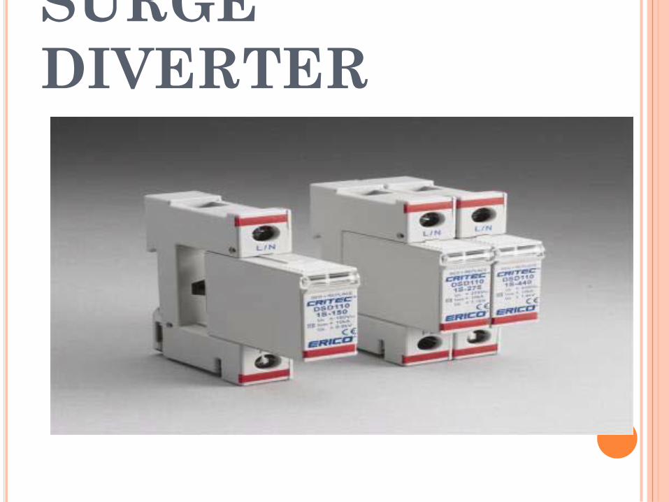
SURGE
DIVERTER
WHAT IS SURGE?
• Surges disturbances on a power
waveform that can damage, or
destroy equipment within any
home, commercial building, or
manufacturing facility.
• Surges are measured in
microseconds.
SURGE DIVERTERS
• A surge diverter is a piece ofequipment that diverts excessvoltages to earth, thusprotecting sensitive electricaland electronic equipment.
• The surge diverter is normallyinstalled in the mainswitchboard.
REQUIREMENT OF SURGE
DIVERTER
• It should not pass any current at normal and abnormalpower frequency voltage.
• It should breakdown as quickly as possible after theabnormal high frequency voltage arrives.
• It should not only protect the equipment for which it isused but should discharge current without damagingitself.
• It should interrupt power frequency follow currentafter the surge is discharge to ground.
TYPES OF SURGE
DIVERTERS
Rod gap type surge diverter.
Protector tube or expulsion
type surge diverter.
Valve type surge diverter.
1. ROD GAP TYPE SURGE
DIVERTER
• It is a very simple type of diverter andconsists of two 1.5 cm rods.
• One rod is connected to the line circuitand the other rod is connected to earth.
• The distance between gap and insulatormust not be less than one third of thegap length so that the arc may not reachthe insulator and damage it.
• The rod gap should be so set that itbreaks down to a voltage not less than30% below the voltage withstand level ofthe equipment to be protected.
ROD GAP TYPE SURGE DIVERTER
ROD GAP TYPE SURGE DIVERTER
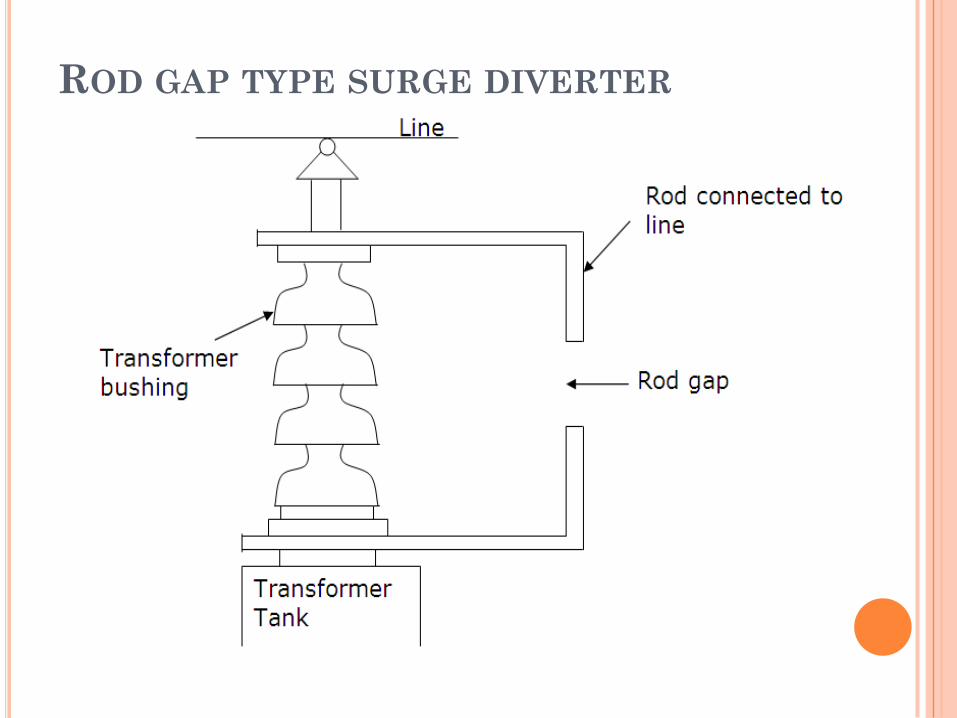
• The string of insulators for an overhead line on the bushing of transformer has frequently a rod gap across it.
• Under normal operating conditions, the gap remains non-conducting.
• On the occurrence of a high voltage surge on the line, the gap sparks over and the surge current is conducted to earth.
• In this way excess charge on the line due to the surge is harmlessly conducted to earth.

ROD GAP TYPE SURGE DIVERTER
Limitations :
• After the surge is over, the arc in the gap is maintained by the normal supply voltage, leading to short-circuit on the system.
• The rods may melt or get damaged due to excessive heat produced by the arc.
• The climatic conditions (e.g. rain, humidity, temperature etc.) affect the performance of rod gap arrester.
• The polarity of the surge also affects the performance of this arrester.

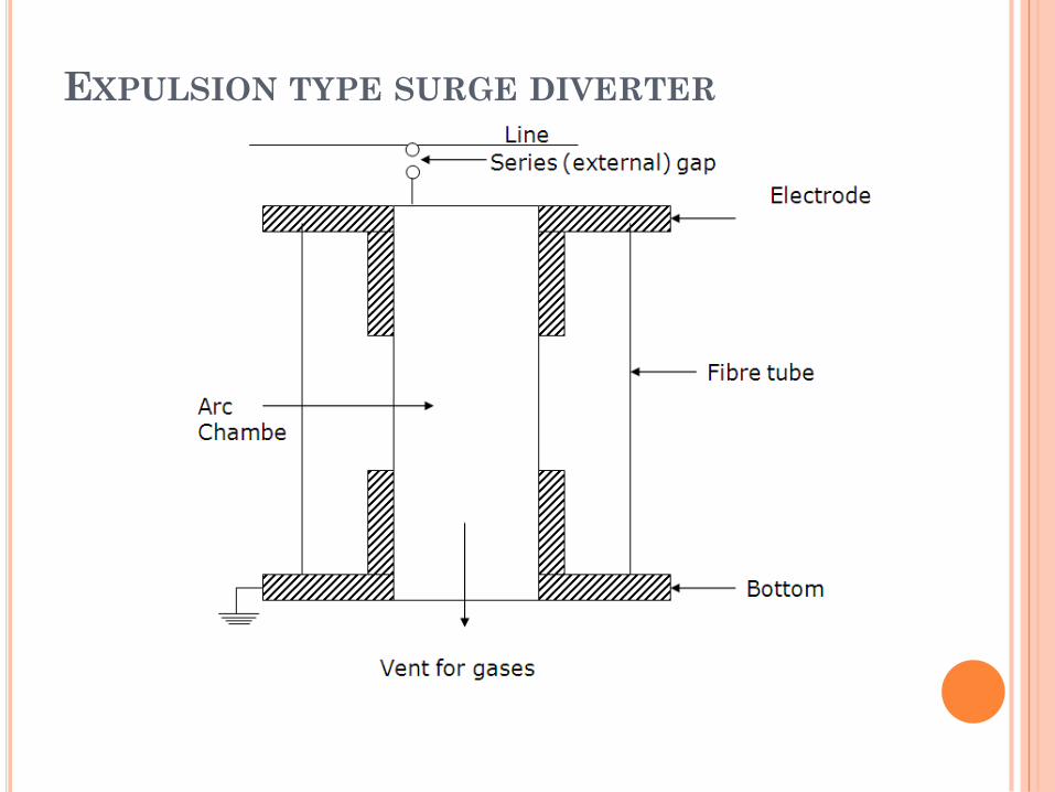
2. EXPULSION TYPE SURGE DIVERTER
This type of arrester is also called „protector tube‟
and is commonly used on system operating at voltages
up to 33kV.
It essentially consists of a rod gap in series with a
second gap enclosed within the fiber tube.
The gap in the fiber tube is formed by two electrodes.
The upper electrode is connected to rod gap and the
lower electrode to the earth.
EXPULSION TYPE SURGE DIVERTER
EXPULSION TYPE SURGE DIVERTER
• The series gap is set to arc over at a specified voltage lowerthan the withstand voltage of the equipment to beprotected.
• The follow-on current is confined to the space inside therelatively small fibre tube.
• Part of the tube material vaporizes, and the high pressuregases so formed are expelled through the vent at the lowerend of the tube, causing the power follow-in arc to beextinguished.
• The device, therefore, has the desired self-clearing property.
EXPULSION TYPE SURGE DIVERTER
Advantages
• They are not very expensive.
• They can be easily installed.
• They are improved form of rod gap arresters as they
block the flow of power frequency follow currents.
EXPULSION TYPE SURGE DIVERTER
Limitations
• An expulsion type arrester can perform only limited
number of operations as during each operation some of the
fiber material is used up.
• This type of arrester cannot be mounted on enclosed
equipment due to discharge of gases during operation.
• Due to the poor volt/amp characteristic of the arrester, it is
not suitable for protection of expensive equipment.
3. VALVE TYPE SURGE DIVERTER
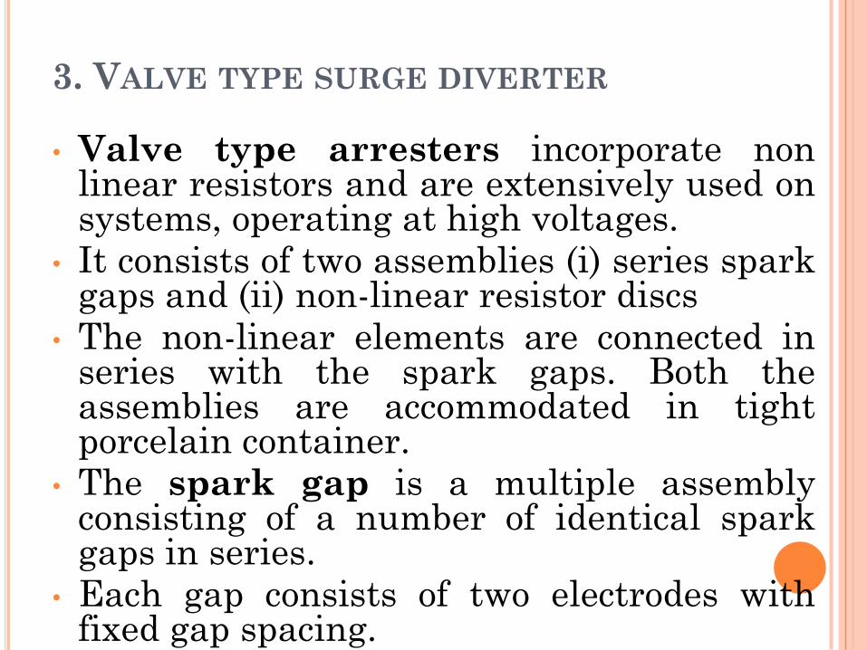
• Valve type arresters incorporate nonlinear resistors and are extensively used onsystems, operating at high voltages.
• It consists of two assemblies (i) series sparkgaps and (ii) non-linear resistor discs
• The non-linear elements are connected inseries with the spark gaps. Both theassemblies are accommodated in tightporcelain container.
• The spark gap is a multiple assemblyconsisting of a number of identical sparkgaps in series.
• Each gap consists of two electrodes withfixed gap spacing.
VALVE TYPE SURGE DIVERTER
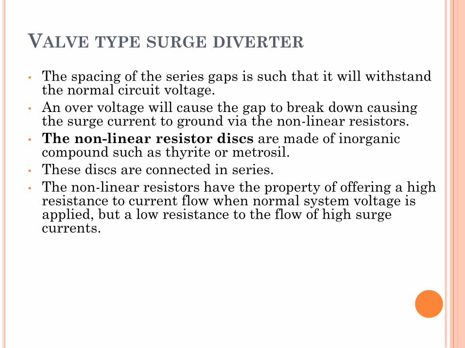
• The spacing of the series gaps is such that it will withstand the normal circuit voltage.
• An over voltage will cause the gap to break down causing the surge current to ground via the non-linear resistors.
• The non-linear resistor discs are made of inorganic compound such as thyrite or metrosil.
• These discs are connected in series.
• The non-linear resistors have the property of offering a high resistance to current flow when normal system voltage is applied, but a low resistance to the flow of high surge currents.
VALVE TYPE SURGE DIVERTER
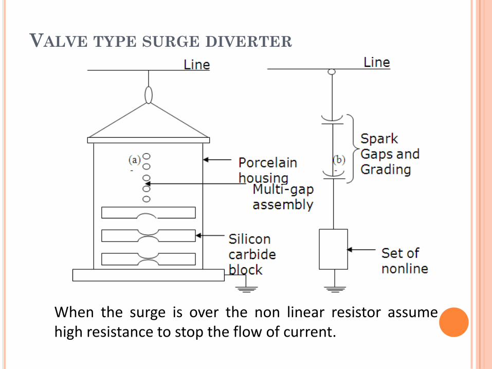
When the surge is over the non linear resistor assumehigh resistance to stop the flow of current.
VALVE TYPE SURGE DIVERTER
• Under normal conditions, the normal system voltage is insufficient to cause the breakdown of air gap assembly.
• On the occurrence of an over voltage, the breakdown of the series spark gap takes place and the surge current is conducted to earth via the nonlinear resistances.
• Since the magnitude of surge current is very large, the nonlinear elements will offer a very low resistance to the passage of surge.
• The surge will rapidly go to earth instead of being sent back over the line.
VALVE TYPE SURGE DIVERTER
ADVANTAGES :
• They provide very effective protection against surges.
• They operate very rapidly taking less than a second
• The impulse ratio is practically unity.
VALVE TYPE SURGE DIVERTER
Limitations :
• They may fail to check the surge ofvery steep wave front reaching theterminal apparatus. This calls foradditional steps to check steep frontedwaves.
• Their performance is adverselyaffected by the entry of moisture intothe enclosure. This necessitateseffective sealing of the enclosure at alltimes.

SURGE ABSORBER
SURGE ABSORBER
• The Device which reduces the steepness of the wave
front of a particular surge & thus minimizes the
danger due to over voltage is known as surge absorber.
Note:
Surge Diverter : Diverts the Surge to earth
Surge Absorber : Absorbs the Surge energy
TYPES OF SURGE ABSORBER
Ferranti Surge absorber
ERA Surge absorber
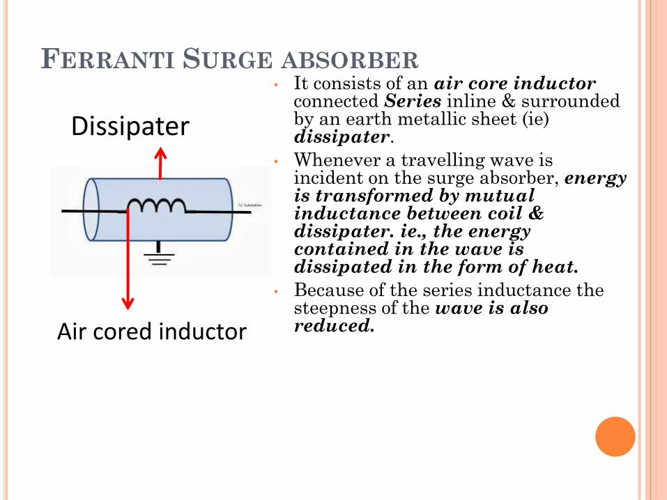
FERRANTI SURGE ABSORBER• It consists of an air core inductor
connected Series inline & surrounded by an earth metallic sheet (ie) dissipater.
• Whenever a travelling wave is incident on the surge absorber, energy is transformed by mutual inductance between coil & dissipater. ie., the energy contained in the wave is dissipated in the form of heat.
• Because of the series inductance the steepness of the wave is also reduced.Air cored inductor
Dissipater
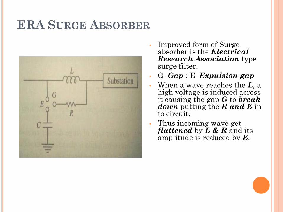
ERA SURGE ABSORBER
• Improved form of Surge absorber is the Electrical Research Association type surge filter.
• G–Gap ; E–Expulsion gap
• When a wave reaches the L, a high voltage is induced across it causing the gap G to break down putting the R and E in to circuit.
• Thus incoming wave get flattened by L & R and its amplitude is reduced by E.
BASIC IDEAS OF
INSULATION CO-
ORDINATION
INSULATION COORDINATION
• Correlating (link) apparatusinsulation with insulation of theprotective device to achieveoverall protection is known asinsulation coordination.
• The insulation strength ofvarious equipments should behigher than that of lightningarresters and other surgeprotective devices.
INSULATION COORDINATION
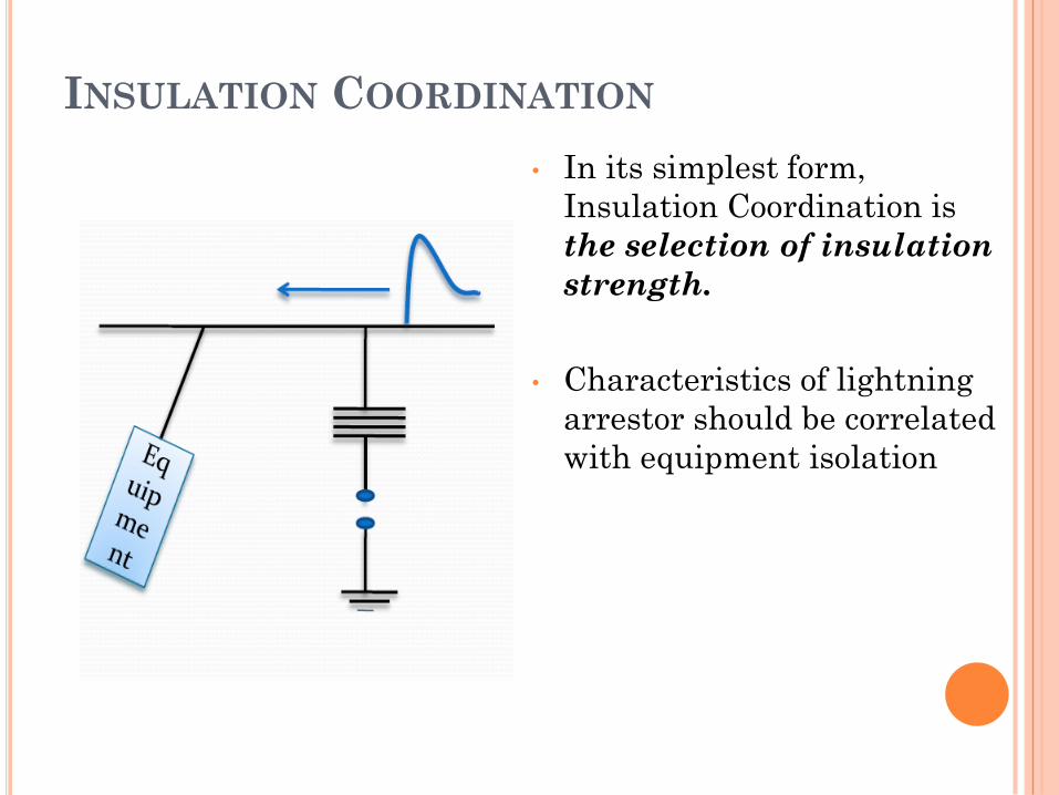
• In its simplest form,
Insulation Coordination is
the selection of insulation
strength.
• Characteristics of lightning
arrestor should be correlated
with equipment isolation
INSULATION COORDINATION
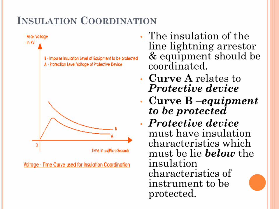
• The insulation of the line lightning arrestor & equipment should be coordinated.
• Curve A relates to Protective device
• Curve B –equipment to be protected
• Protective device must have insulation characteristics which must be lie below the insulation characteristics of instrument to be protected.
INSULATION COORDINATION
A perfect insulation coordination must satisfy the
following conditions:
• The insulation should withstand both operating
voltage & voltage surges.
• The discharge of OV due to internal or external causes
must flow to ground efficiently.
• Only external flashover should cause breakdown.
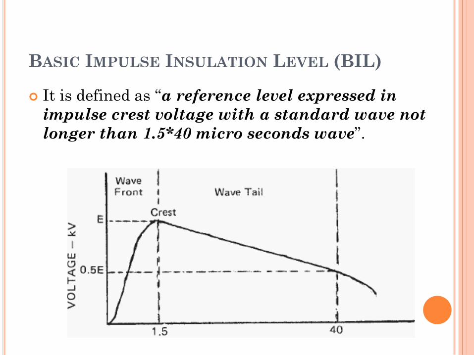
BASIC IMPULSE INSULATION LEVEL (BIL)
It is defined as “a reference level expressed in
impulse crest voltage with a standard wave not
longer than 1.5*40 micro seconds wave”.

THANK YOU


![Eee-Vi-switchgear & Protection [10ee62]-Notes](https://img.pdfslide.us/doc/110x75/55cf9a91550346d033a260b6/eee-vi-switchgear-protection-10ee62-notes.jpg)