Embed Size (px)
Citation preview
INTRODUCTION MACHINES
EE09 605 ELECTRICAL ENGINEERING DRAWING
Akhil A. Balakrishnan1
1Department of Electrical & Electronics EngineeringJyothi Engineering College, Cheruthuruthy
As on February 24, 2014
Akhil A. Balakrishnan (JECC) Lecture Notes As on February 24, 2014 1 / 26
Downloaded from CyberSparkz EEE
Downloaded from akhilbalakrishnan.wordpress.com
INTRODUCTION MACHINES
We will go through...
1 INTRODUCTION
2 MACHINESINDUCTION MACHINE
Akhil A. Balakrishnan (JECC) Lecture Notes As on February 24, 2014 2 / 26
Downloaded from CyberSparkz EEE
Downloaded from akhilbalakrishnan.wordpress.com
INTRODUCTION MACHINES
OBJECTIVES
*To make students to be able to plan and draw different views of electricalmachines and transformers.
*To make the students to draw different types of windings used inelectrical machines.
*Introduction to AutoCAD in Electrical engineering drawing.
Akhil A. Balakrishnan (JECC) Lecture Notes As on February 24, 2014 3 / 26
Downloaded from CyberSparkz EEE
Downloaded from akhilbalakrishnan.wordpress.com
INTRODUCTION MACHINES
SYLLABUS
Module I (12 Hours)DC Windings: Simplex lap and wave dc armature windings.AC Windings: Mush and concentric type single layer three phase acarmature windings. Simplex lap and wave, integral and fractional slot,double layer three phase ac armature windings.Introduction to AutoCad:Developed winding diagrams (Auto Cad notincluded for Examination).
Akhil A. Balakrishnan (JECC) Lecture Notes As on February 24, 2014 4 / 26
Downloaded from CyberSparkz EEE
Downloaded from akhilbalakrishnan.wordpress.com
INTRODUCTION MACHINES
SYLLABUSModule II (14 Hours)
1 Sectional plan and elevation of a transformer limb with windings.2 Sectional plan and elevation of the core assembly of a power
transformer.3 Sectional plan and elevation of a distribution transformer tank with
its accessories.4 Sketches of capacitor and oil filled type transformer bushings.5 Layout and single line diagram of a distribution transformer.
Substation Layouts:1 Layouts and single line diagrams of outdoor and indoor substations.2 Layout of a 220KV substation.3 Layout of a captive power substation.4 Single line diagram of a distribution centre.
Akhil A. Balakrishnan (JECC) Lecture Notes As on February 24, 2014 5 / 26
Downloaded from CyberSparkz EEE
Downloaded from akhilbalakrishnan.wordpress.com
INTRODUCTION MACHINES
SYLLABUSModule III (26 Hours)DC Machines:
1 Sectional front and side elevation of armature with commutator of adc machine.
2 Sectional front and side elevation of the yoke and pole assemblywith field winding of a dc machine.
3 Sectional front and side elevation of an assembled dc Machine.Alternators:
1 Sectional front and side elevation of a water wheel rotor assemblywith winding.
2 Sectional front and side elevation of a salient pole alternator.3 Sectional front and side elevation of a Turbo alternator.4 Sketches of the methods of pole fixing and slot details of Turbo and
Water wheel alternator.Akhil A. Balakrishnan (JECC) Lecture Notes As on February 24, 2014 6 / 26
Downloaded from CyberSparkz EEE
Downloaded from akhilbalakrishnan.wordpress.com
INTRODUCTION MACHINES
REFERENCESText Books
1 Narang K. L., A text book of Electrical Engineering Drawing, TechIndia Publications
2 C. R. Dargan, Electrical Drawing and Estimation, New AsianPublishers
Reference Books1 Bhattacharya S. K., Electrical Engineering Drawing, Wiley Eastern.2 Clayton and Hancock, Performance and design of dc machines,
ELBS.3 Sawhney, Electrical Machine Design, Dhanpath Rai & Sons.4 Say M.G, Performance and design of AC machines, Pitman, ELBS.5 A. Nagoorkani, A simplified text in Electrical Machine Design, RBA
Publications
Akhil A. Balakrishnan (JECC) Lecture Notes As on February 24, 2014 7 / 26
Downloaded from CyberSparkz EEE
Downloaded from akhilbalakrishnan.wordpress.com
INTRODUCTION MACHINES
Internal Continuous Assessment (Maximum Marks - 30)30% - Tests60% - Assignments such as class work, home work10% - Regularity in the class
University Examination PatternQ I - 2 questions A and B of 15 marks from Module I with choice to
answer any one.Q II - 2 questions A and B of 20 marks from Module II with choice to
answer any one.Q III - 2 questions of 35 marks from Module III with choice to answer
any one
Akhil A. Balakrishnan (JECC) Lecture Notes As on February 24, 2014 8 / 26
Downloaded from CyberSparkz EEE
Downloaded from akhilbalakrishnan.wordpress.com
INTRODUCTION MACHINES
INDUCTION MACHINE
Main parts are Stator & Rotor
Akhil A. Balakrishnan (JECC) Lecture Notes As on February 24, 2014 9 / 26
Downloaded from CyberSparkz EEE
Downloaded from akhilbalakrishnan.wordpress.com
INTRODUCTION MACHINES
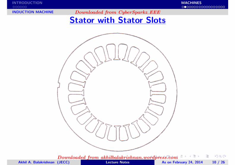
INDUCTION MACHINE
Stator with Stator Slots
Akhil A. Balakrishnan (JECC) Lecture Notes As on February 24, 2014 10 / 26
Downloaded from CyberSparkz EEE
Downloaded from akhilbalakrishnan.wordpress.com
INTRODUCTION MACHINES
INDUCTION MACHINE
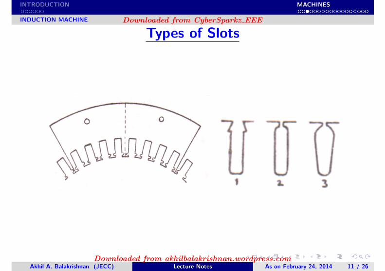
Types of Slots
Akhil A. Balakrishnan (JECC) Lecture Notes As on February 24, 2014 11 / 26
Downloaded from CyberSparkz EEE
Downloaded from akhilbalakrishnan.wordpress.com
INTRODUCTION MACHINES
INDUCTION MACHINE
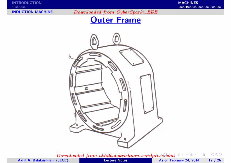
Outer Frame
Akhil A. Balakrishnan (JECC) Lecture Notes As on February 24, 2014 12 / 26
Downloaded from CyberSparkz EEE
Downloaded from akhilbalakrishnan.wordpress.com
INTRODUCTION MACHINES
INDUCTION MACHINE
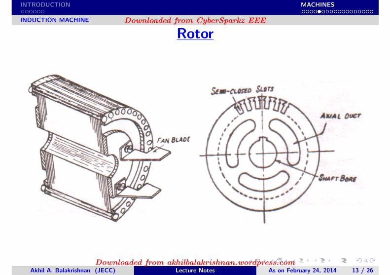
Rotor
Akhil A. Balakrishnan (JECC) Lecture Notes As on February 24, 2014 13 / 26
Downloaded from CyberSparkz EEE
Downloaded from akhilbalakrishnan.wordpress.com
INTRODUCTION MACHINES
INDUCTION MACHINE
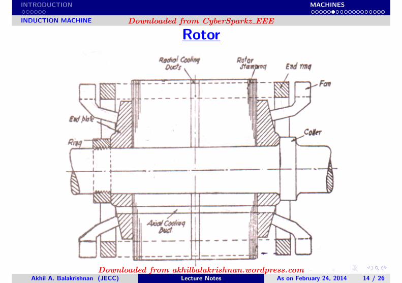
Rotor
Akhil A. Balakrishnan (JECC) Lecture Notes As on February 24, 2014 14 / 26
Downloaded from CyberSparkz EEE
Downloaded from akhilbalakrishnan.wordpress.com
INTRODUCTION MACHINES
INDUCTION MACHINE
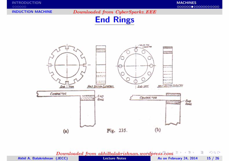
End Rings
Akhil A. Balakrishnan (JECC) Lecture Notes As on February 24, 2014 15 / 26
Downloaded from CyberSparkz EEE
Downloaded from akhilbalakrishnan.wordpress.com
INTRODUCTION MACHINES
INDUCTION MACHINE
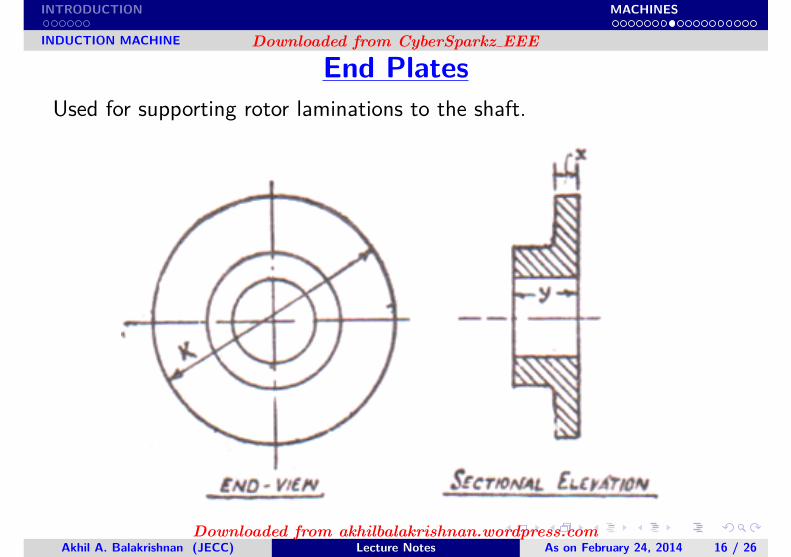
End PlatesUsed for supporting rotor laminations to the shaft.
Akhil A. Balakrishnan (JECC) Lecture Notes As on February 24, 2014 16 / 26
Downloaded from CyberSparkz EEE
Downloaded from akhilbalakrishnan.wordpress.com
INTRODUCTION MACHINES
INDUCTION MACHINE
INDUCTION MACHINE
Example 1
Draw end view and elevation of the stator stamping of the given belowdimensions
Akhil A. Balakrishnan (JECC) Lecture Notes As on February 24, 2014 17 / 26
Downloaded from CyberSparkz EEE
Downloaded from akhilbalakrishnan.wordpress.com
INTRODUCTION MACHINES
INDUCTION MACHINE
INDUCTION MACHINE
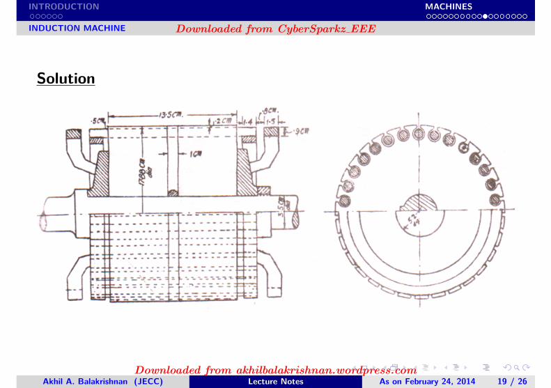
Example 3
Draw the half sectional end view and half sectional elevation of thesquirrel cage rotor directly mounted over the shaft. Show clearly themethod of fixing the rotor with the shaft.Diameter of rotor = 17.88cmLength of rotor = 13.5cmOne radial cooling duct = 1cm wideRotor conductor dia. = 0.9cmDistance between end ring and core = 0.5cmDia. of shaft below rotor core = 3.5cmSix vanes are fixed o the rotor end plates to help the cooling.
Akhil A. Balakrishnan (JECC) Lecture Notes As on February 24, 2014 18 / 26
Downloaded from CyberSparkz EEE
Downloaded from akhilbalakrishnan.wordpress.com
INTRODUCTION MACHINES
INDUCTION MACHINE
Solution
Akhil A. Balakrishnan (JECC) Lecture Notes As on February 24, 2014 19 / 26
Downloaded from CyberSparkz EEE
Downloaded from akhilbalakrishnan.wordpress.com
INTRODUCTION MACHINES
INDUCTION MACHINE
INDUCTION MACHINE
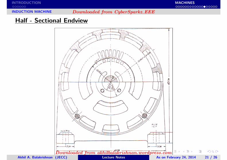
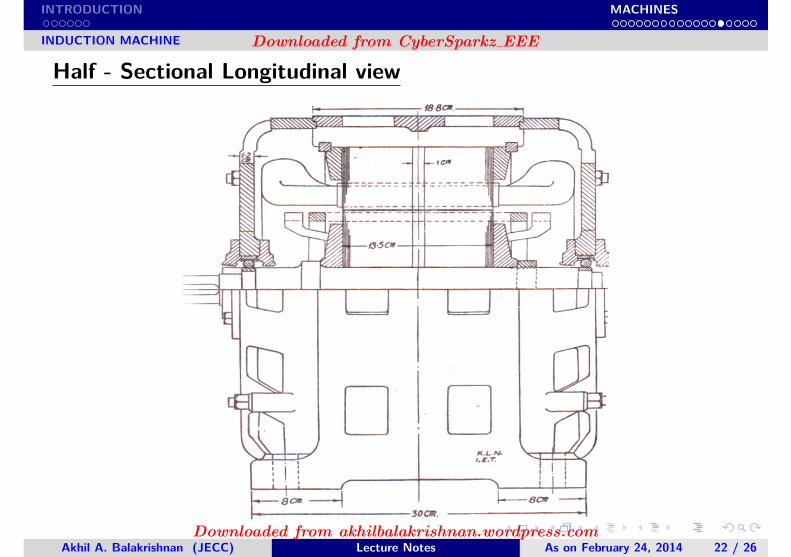
Example 4
Draw the half sectional end view and half sectional elevation of a 10hpsquirrel cage motor with the following dimensions.Inside dia. of stator = 18cmLength of stator = 13.5cmOn radial cooling duct in stator and rotor = 1cm wideStator slot size = 0.95cm * 2.9cmOutside dia. of stator = 32cmAir gap length = 0.06cmRotor has 31 slots of size 1cm dia. and is directly mounted over the shaft.Dia. of shaft below rotor = 2.4cmThe rotor shaft is supported in the end cover by means of ball bearings.Other missing data may be assumed.
Akhil A. Balakrishnan (JECC) Lecture Notes As on February 24, 2014 20 / 26
Downloaded from CyberSparkz EEE
Downloaded from akhilbalakrishnan.wordpress.com
INTRODUCTION MACHINES
INDUCTION MACHINE
Half - Sectional Endview
Akhil A. Balakrishnan (JECC) Lecture Notes As on February 24, 2014 21 / 26
Downloaded from CyberSparkz EEE
Downloaded from akhilbalakrishnan.wordpress.com
INTRODUCTION MACHINES
INDUCTION MACHINE
Half - Sectional Longitudinal view
Akhil A. Balakrishnan (JECC) Lecture Notes As on February 24, 2014 22 / 26
Downloaded from CyberSparkz EEE
Downloaded from akhilbalakrishnan.wordpress.com
INTRODUCTION MACHINES
INDUCTION MACHINE
INDUCTION MACHINE
Example 6
A three phase induction motor is of slip ring type. The slip rings whichare mounted on a projection of the shaft at right hand end are connectedto the winding by insulated conductor passing through a hole in theshaft, and a slip ring cover with the movable lid is supported from theend shield. The left hand of the shaft supports the fan inside the casingand projects through the ball bearing to carry the driving pulley.
The ventilation is of mixed flow type being partly axial and partlyradial. Under the action of the fan air enters at the slip ring and flowsthrough the duct in the rotor and over the stator plates. Some of therotor air flows through the two radial ducts. All the air is exhausted fromthe machine at the pulley end.
Akhil A. Balakrishnan (JECC) Lecture Notes As on February 24, 2014 23 / 26
Downloaded from CyberSparkz EEE
Downloaded from akhilbalakrishnan.wordpress.com
INTRODUCTION MACHINES
INDUCTION MACHINE
Diameter of shaft = 2”Internal diameter of the stator stamping = 9”External diameter of the stator stamping = 15”Length of the stator core = 8”Stator winding overhang on each side = 2”Width of pulley = 6”Assume the missing dimensionsDraw to 1/2 scale:(a) Half-sectional longitudinal view showing the stator, slip rings and thefan.(b) Half-sectional end view of the induction motor
Akhil A. Balakrishnan (JECC) Lecture Notes As on February 24, 2014 24 / 26
Downloaded from CyberSparkz EEE
Downloaded from akhilbalakrishnan.wordpress.com
INTRODUCTION MACHINES
INDUCTION MACHINE
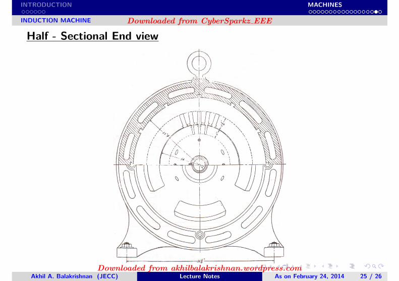
Half - Sectional End view
Akhil A. Balakrishnan (JECC) Lecture Notes As on February 24, 2014 25 / 26
Downloaded from CyberSparkz EEE
Downloaded from akhilbalakrishnan.wordpress.com
INTRODUCTION MACHINES
INDUCTION MACHINE
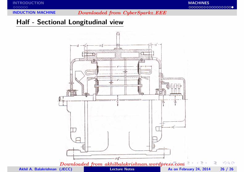
Half - Sectional Longitudinal view
Akhil A. Balakrishnan (JECC) Lecture Notes As on February 24, 2014 26 / 26
Downloaded from CyberSparkz EEE
Downloaded from akhilbalakrishnan.wordpress.com