Embed Size (px)
Citation preview
1008 MAIN PAPER - EE
EE: ELECTRICAL ENGINEERING
Duration; Three Hours MaxilllulII Marks: 150
Read tbe following instructions carefully
EE
I. This question paper comains 28 printed pages including pages for rough work. Please check all pages and report discrepancy, if any.
2. Write your registration number. your name and name of the examination centre at the specified locations on the right half of the ORS.
3. Using HB pencil, darken the appropriate bubble under each digit of your registration number and the letters corresponding to your paper code.
4. All the questions in this question paper are of objective type.
5. Questions must be answered on Objective Response Sheet (ORS) by darkening the appropriate bubble (marked A, B, C, D) using HB pencil against the question number on the left hand side of the ORS. Eacb question bas only one correct answer. In case you wish to change an answer, erase the old answer completely. More than one answer bubbled against a question will be treated as a wrong answer.
6. Questions I through 20 are I-mark questions and questions 21 through 85 are 2-mark questions.
7. Questions 71 through 73 is one set of common data questions, questions 74 and 75 is another pair of common data questions. The questiOn pairs (76, 77), (78, 79). (80, 81), (82, 83) and (84, 85) are questions with linked answers. The answer to the second question of the above pairs wi ll depend on the answer 10 the first question of the pair. If the first question in the linked pair is wrongly answered or is un-attempted, then the answer to the second question in the pair will not be evaluated.
8. Un-attempted questions will carry zero marks.
9. NEGATIVE MARKING: For Q.I to Q.20, 0.25 mark will be deducted for each wrong answer. For Q.21 10 Q.75, 0.5 mark will be deducted for each wrong answer. For the pairs of questions with linked answers, there will be negative marks only for wrong answer 10 the first question. i.e. for Q.76. Q.78, Q.80, Q.82 and Q.84, 0.5 mark will be deducted for each wrong answer. There is no negative marking for Q.77, Q.79, Q.81, Q.83 and Q.85.
10. Calculator witbout data connectivity is allowed in the examination hall.
II. Charts, graph sheets and tables are NOT allowed in the examination hall.
12. Rough work can be done on the question paper itself. Additional blank pages are given at the end of the question paper for rough work.
1/18

:W08 MAIN PAPER - EE
Q. 1 - Q. 20 carry one mark each.
Q.I The number of chords in the graph of the given circuit will be
(A) 3 (8) 4 (C) 5 (D) 6
Q.2 The Thevenin's equivalent of a circuit operating at w=5 rad/s, has Yoc =3.71L-!5.9°y and
Zo=2.38 - jO.667 Q. At this frequency, the minimal realization of the Thevenin's impedance will
have a
(A) resistor and a capacitor and an inductor (C) resistor and an inductor
(8) resistor and a capacitor (D) capacitor and an inductor
Q.3 A signal e-a'sin(Wl) is the input to a real Linear Time Invariant system. Given K and 1/1 are
constants, the output of the system will be of the form Ke-P' sin(V/ + 1/1) where
(A) fJ need not be equal to a but v equal to w (8) v need not be equal to w but fJ equal to a (C) fJ equal to a and v equal to w (0) fJ need not be eqllal to a and V need not be equal to W
QA X is a uniformly distributed random variable that takes values between 0 and I. The value of
E{ X'} will be
(A) 0 (8) 118 (C) 114 (D) 1/2
Q.5 The characteristic equation of a (3x3) malrix P is defined as
a(A) =IAI -pi = A' +A' +2A+! = O.
If 1 denotes identity matrix, then the inverse of matrix P will be
(A) (p' +P+21) (8) (P'+P+I) (C) -(p' + P+ I) (D) -(p' + P+ 21 )
Q.6 If the rank of a (5x 6) malrix Q is 4, then which one of the following statements is correct?
EE
(A) Q will have four linearly independent rows and four linearly independent columns
(B) Q will have four linearly independent rows and five linearly independent columns
(C) Q QT will be invertible
(D) Q TQ will be invertible
2128
2008, MAIN PAPER - EE
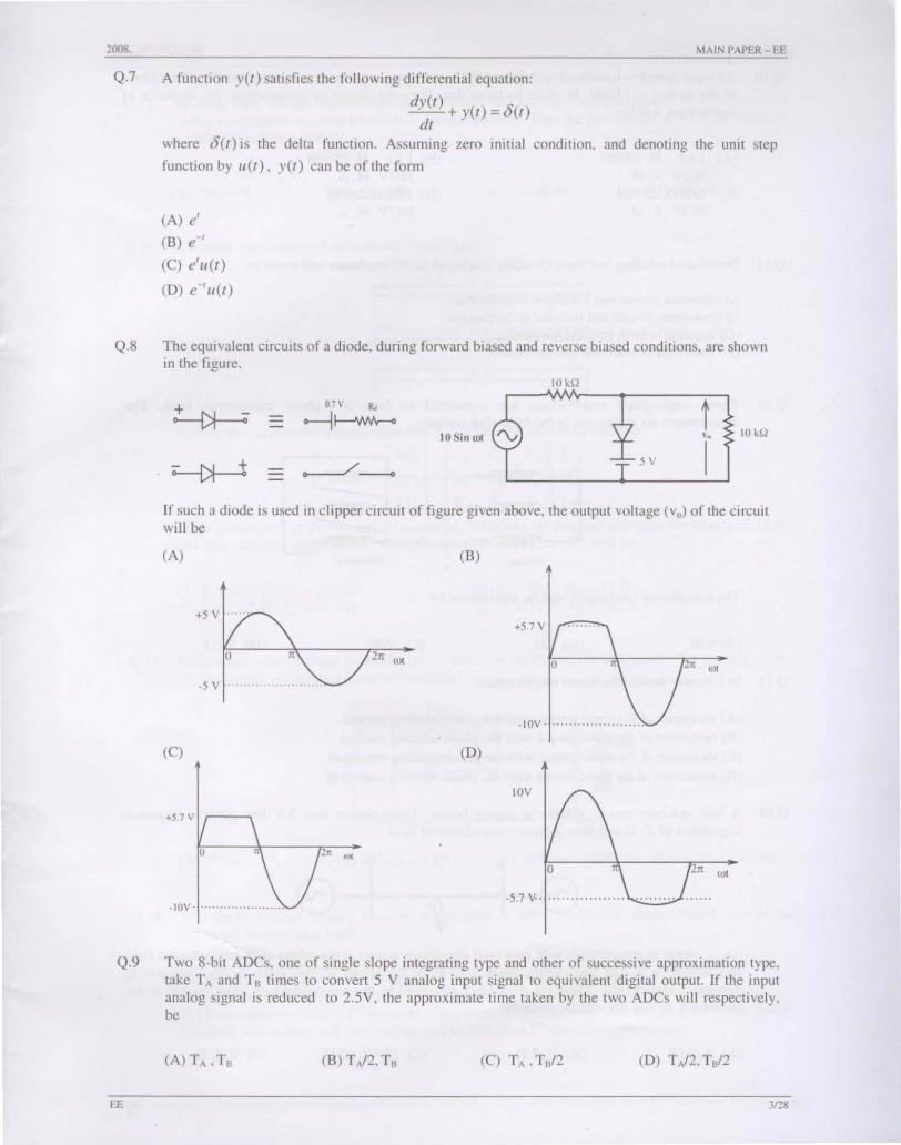
Q.7 A function Y(l) satisfies the followi ng differential equation:
dy(t) + y(l) = 8(t ) dl
where 8(t) is the delta function. Assuming zero initial condition, and denoting the unit step
function by lI(t) , yet) can be of the form
(A) e' (B) e-' (C) e'u(t)
(D) e-' 1I.(r)
Q.8 The equivalent circuits of a diode, during forward biased and reverse biased conditions, are shown in the figure.
IOkQ
~ OJ v .. t ........j i---'Wv'r--<
IOk(l Vo
~ .--- ,,".---. 5V I
If such a diode is used in clipper circuit of figure given above, the output voltage (vo) of the circuit will be
(A) (B)
2n wt
~IOV' ......... ........... .
(C) (D)
JOV
o 21t (JX
o 2n wt
-IOV' ..................... . -5.7 V .. ................. ____ __
Q.9 Two 8-bit ADes. one of single slope integrating type and other of successive approximation type, take TA and TB times to convert 5 V analog input signal to equivalent digital output. If the inpul analog signal is reduced to 2.5V, the approximate time taken by the two ADes will respectively. be
(A)TA ,Ta (B) TA/2,Ta (e) TA • Tal2
EE 3118
2008 MAINPAPER-EE
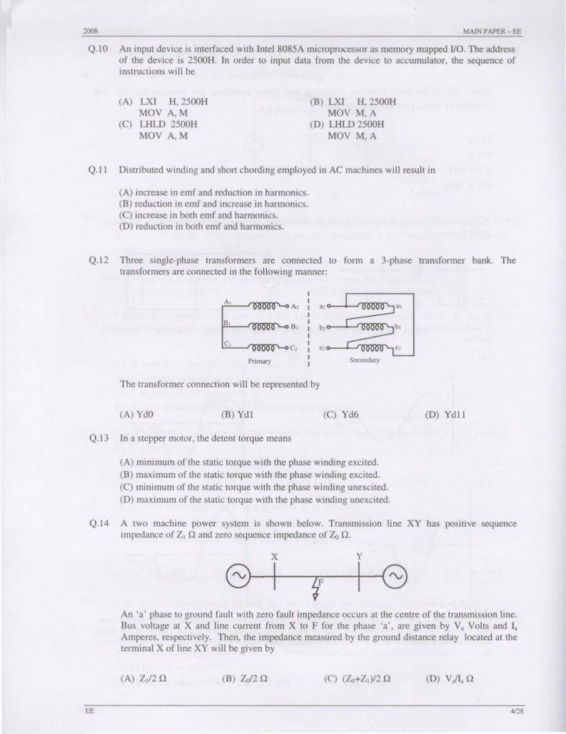
Q.10 An input device is interfaced with Intel 8085A microprocessor as memory mapped 110. The address of the device is 2500H. In order to input data from the device to accumulator, the sequence of instructions will be
(A) LXI H, 2500H MOV A,M
(C) LHLD 2500H MOV A,M
(B) LXI H, 2500H MOV M,A
(D) LHLD 2500H MOV M,A
Q.II Distributed winding and short chording employed in AC machines will result in
(A) increase in emf and reduction in harmonics. (B) reduction in emf and increase in harmonics. (C) increase in both emf and harmonics. (D) reduction in both emf and harmonics.
Q.12 Three single-phase transformers are connected to form a 3-phase transformer bank. The transformers are connected in the following manner:
I
E " I , a:: " ,
BI B:: , , In ,
C! Cl I , c,
Primary I Secondary , The transformer connection will be represented by
(A) YdO (B)Yd! (C) Yd6 (D) Ydl I
Q.13 In a stepper motor, the detent torque means
(A) minimum of the static torque with the phase winding excited. (B) maximum of the static torque with the phase winding excited. (C) minimum of the static torque with the phase winding unexcited. (D) maximum of the static torque with the phase winding unexcited.
Q.14 A twO machine power system is shown below. Transmission line XV has positive sequence impedance of Z, Q and zero sequence impedance of Zo Q.
EE
x y
G---+I--r.::-1F -+-'1 G An 'a' phase to ground fault with zero fault impedance occurs at the centre of the transmission Jine. Bus voltage at X and line current from X to F for the phase 'a', are given by V, Volts and I, Amperes, respectively. Then, the impedance measured by the ground distance relay located at the terminal X of line XY will be given by
(A) Z,/2 Q (B) Zo/2 Q (0) V,II, Q
4128

2()()8 MAIN PAPER - EE
Q.IS An extra high voltage transmission line of length 300 km can be approximated by a lossless line having propagation constant ~= 0.00127 radians per km. Then the percentage ratio of line length to wavelength will be given by
(A) 24.24 % (B) 12.12% (C) 19.0S % (D) 6.06 %
Q.16 A 3-phase transmission line is shown in the figure:
," I:!. V. ~, ..
I.
'" I:!. V. ~, ..
I.
'"
I:!. Ve ~, • Ie
Voltage drop across the transmission line is given by the following equation:
[t.Vn]=[Z' Zm Zm][/o] t.V. Zm Z, Zm I. t.Ve Zm Zm Z, Ie
Shunt capacitance of the line can be neglected. If the line has positive sequence impedance of IS n and zero sequence impedance of 48 n, then the values of Z, and 2" will be
(A) Z. = 31.S n; z,. = 16.S n (C) Z. = 16.S n; z.. = 31.S n
(B) Z. = 26 n; z,. = II n (D) Z. = II n ; z.. = 26 n
Q.I7 In the single phase voltage controller circuit shown in the figure, for what range of triggering angle (a), the output voltage (vo) is nOl controllable?
i son +
v.
I
(A) 00 < a < 4So (B) 4So < a < 13So (C) 900 < a < 1800 (D) I3So < a < 1800
Q.18 A 3-phase Voltage Source Invener is operated in 1800 conduction mode. Which one of the following statements is true?
EE
(A) Both pole-voltage and line-voltage will have 3'" harmonic components (B) Pole-voltage will have 3'" harmonic component but line-voltage will be free from 3'" harmonic (C) Line-voltage will have 3'" harmonic component but pole-voltage will be free from 3'" harmonic (D) Both pole-voltage and line-voltage will be free from 3'" harmonic components

2008 MAIN PAPER - EE
Q.19 The impulse response of a causal li near time-invariant system is given as h(t). Now consider the following two statements: Statement (I): Principle of superposition holds Statement (1I): h(t) = 0 for t < O.
Which one of the following statements is correct?
(A) Statement (1) is correct and Statement (II) is wrong (B) Statement (II) is correct and Statement (1) is wrong (C) Both Statement (1) and Statement (II) are wrong (D) Both Statement (I) and Statement (ll) are COITect
Q.20 It is desired to measure parameters of 230 Y I 115 Y, 2 kYA, single-phase transformer. The following wattmeters are available in a laboratory:
WI: 250 Y, to A, Low Power Factor W,: 250 Y, 5 A. Low Power Factor W,: 150 Y, 10 A, High Power Factor W,: 150 Y, 5 A, High Power Factor
The wattmeters used in open circuit test and short circuit test of the transformer will respectively be
(A) W, and W, (B) W, and W, (C) W, and W, (D) W, and W,
Q. 21 to Q.75 carry two marks each.
Q.21 The time constant for the given circu it will be
(A) 1/9 s (8) 1/4s (C) 4 s
Q.22 The resonant frequency for the given circuit will be
0.1 H
(A) I rad/s (B) 2 radls
EE
I F
(C) 3 radls
3 A
(D) 9 s
IQ
(D) 4 md/s
6/28
2008 MAIN PAPER - EE
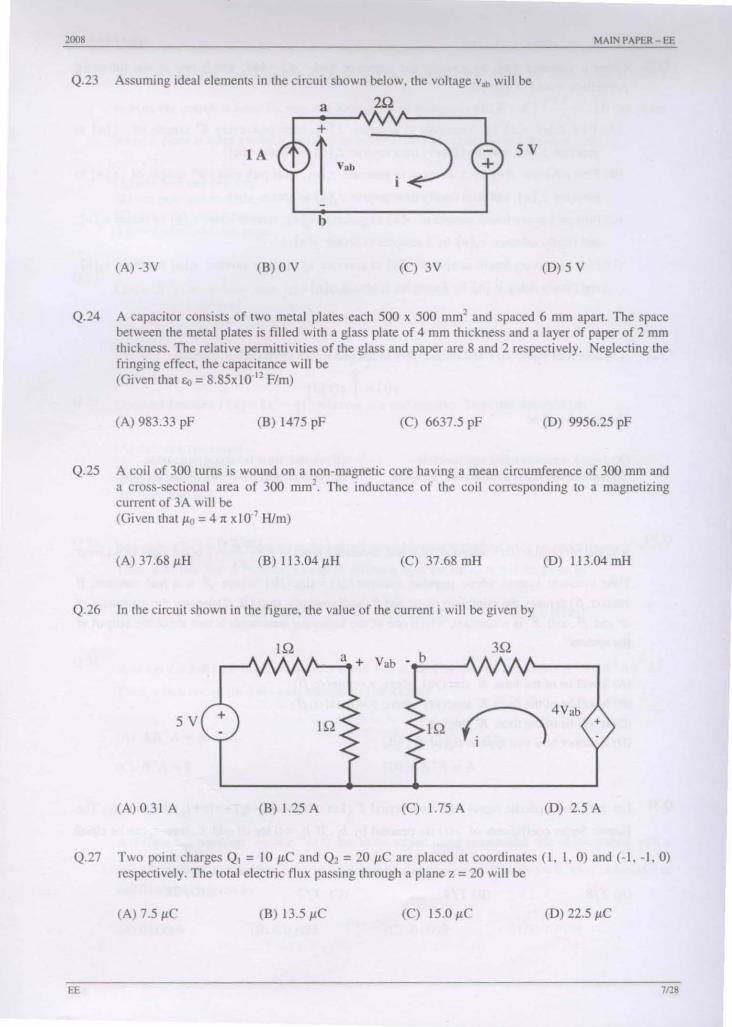
Q.23 Assuming ideal elements in the circuit shown below, the voltage v", will be
a
sv lA j+ V"b ~ i~
b
(A) -3V (B) 0 V (C) 3V (D) 5 V
Q.24 A capacitor consists of two metal plates each 500 x 500 mm' and spaced 6 mm apart. The space between the metal plates is filled with a glass plate of 4 mm thickness and a layer of paper of 2 mm thickness. The relative permittivities of the glass and paper are 8 and 2 respectively. Neglecting the fringing effect, the capacitance will be (Given that 60 = 8.85x1O·12 F/m)
(A) 983.33 pF (B) 1475 pF (e) 6637.5 pF (D) 9956.25 pF
Q.25 A coil of 300 turns is wound on a non-magnetic core having a mean circumference of 300 mm and a cross-sectional area of 300 mm'. The inductance of the coil corresponding to a magnetizing current of 3A will be (Given that Jl<J = 4" x 10·' Him)
(A) 37.68 JLH (B) 113.04 JLH (C) 37.68 mH (D) 113.04 mH
Q.26 In the circuit shown in the figure, the value of the current i will be given by
IQ I,-_a_+ Vab _~b __ ..J\
3Q
5V + IQ IQ ~ 4 V
ab +
(Al 0.31 A (B) 1.25 A (el 175 A (D) 2.5 A
Q.27 Two point charges QJ = 10 JLe and Q, = 20 JLe are placed at coordinates (1, 1,0) and (-1, -1, 0) respectively. The total electric flux passing through a plane z = 20 will be
(B) 13.5 JLe (0) 22.5 JLe
EE 712&
2008 MAIN I'APER- EE
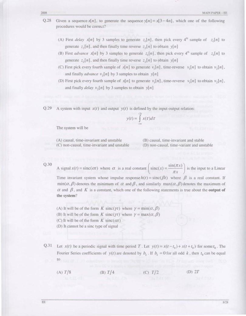
Q.28 Given a sequence x(n). to generate the sequence YIII ] = x[3 - 411J, which one of the following
procedures would be correct?
(A) First delay x[n] by 3 samples to generate 2,[11]. then pick every 4'h sample of <,[n) to
generate <,[n], and then finally time reverse Z'[II] to obtain y[lI]
(B) First advance x[n] by 3 samples to generate z,[n]. then pick every 4'h sample or <,[II] to
generate Z,[II]. and then finally time reverse Z,[II] to obtain y[n)
(C) First pick every fOUIth sample of X[II] to generate v,[n] , time-reverse V,[II] to obtain v,[Il],
and finally advance v,[n] by 3 samples to obtain y[n]
(D) First pick every rou,th sample of X[II] to generate v,[n]. time-reverse v,ln] to obtain v,[Il],
and finally delay ",[n] by 3 samples to obtain y[n]
Q.29 A system with input X(I} and output y(l) is defined by the input-output relation:
Q.30
-,. y(l) = J x(T}dT
The system will be
(A) causal, time-invariant and unstable (B) causal, time-invariant and stable (C) non-causal, time-invariant and unstable (D) non-causal, time-variant and unstable
. ( ) . ( ) . (. () Sin(nX»).. . A s'gnal x I = smc at where a ,s a real constant smc x = 's the 1I1put to a L1I1ear nx
Time invariant system whose impulse responseh(l) = sinc(pt) where P is a real constant. If
min(a,p) denotes the minimum or a andp, and similarly max(a,p}denOies the maximum of
a and p, and K is a constant, whieh one of the following statements is true about the output of
the system?
(A) It will be or the form K sinc(rt} where r = min(a, P} (B) It will be or the form K sinc(rl) where r = max(a, P) (C) It will be or the form K sinc( al) (D) It cannot be a sine type of signal
Q.31 Let X(I) bea periodic signal with time period T.Let y(I}=X(t-Io)+X(t+lo) forsometo.The
Fourier Series coefficients or y(l} are denoted by b, . If b, = 0 for all odd k, then 10 can be equal
to
(A) T/8 (B) T/4 (e) T/2 (D) 2T
EE 8128

2008
Q.32
Q.33
MAIN I>APER- EE
H(z) is a transfer function of a real system. When a signal X[II] = (1 + if is the input to such a
system. the output is zero. Further, the Region Of Convergence (ROC) of (I -~ Z-I) H (Z) is the
entire Z-planc (except Z = 0). It can then be infen'ed that H (z) can have a minimum of
(A) one pole and one zero (B) one pole and two zeros (C) two poles and one zero (D) two poles and two zeros
Given X(z) __ z'--::- with Izl > a, the residue of X (Z)Z,-I at Z = a for II ~ 0 will be (z-a)'
(B) a" (C) Ila" (D) Ila,-I
Q.34 Consider function f(x) = (x' _4)' wherex is a real number. Then the function has
(A) only one minimum (B) only two minima (C) three minima (D) three maxima
Q.35 Equation eX -1 = 0 is required to be solved using Newton's method with an initial guess x, = -1.
Q.36
Q.37
EE
Then, after one step of Newton'S method, eSlimate XI of the solution will be given by
CA) 0.71828 (B) 0.36784 (C) 0.20587 (D) 0.00000
A is amXIl full rank matrix with I1l > 11 and [i s an identity matrix. Let matrix A' = (A TAt AT.
Then, which one of the following statements is FALSE?
(A) AA' A = A
(C) A' A = I
(B) (AA')' = AA'
(0) AA'A = A'
A differential equation dx = e-2'u(l) has to be solved using trapezoidal rule of integration with a dl
step size h=O.OI s. Function 1/.(1) indicates a unit step function. If x(O-) = O. then vaIue of x at
1=0.01 s will be given by:
(A) 0.00099 (B) 0.00495 (C) 0.0099 (D) 0.0198
9/28
2008 MAIN PAPER - EE
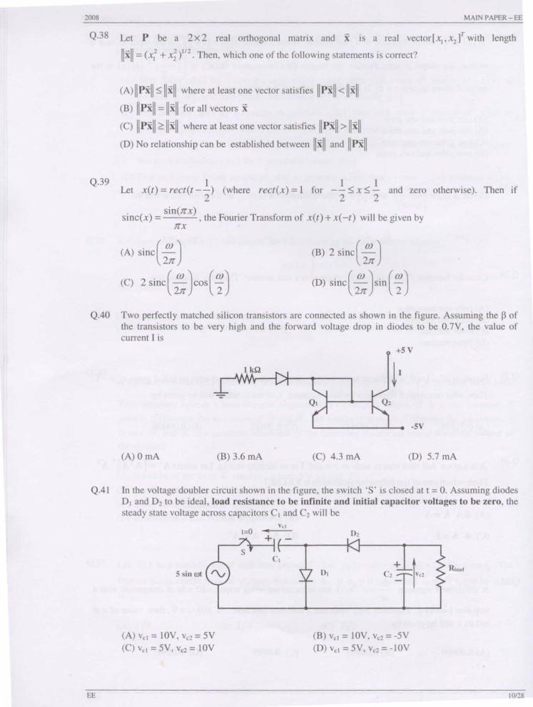
Q.38 Let P be a 2x2 real orthogonal matrix and X is a real vector Lx"x,l' with length
IIxll = (x,' + xi)'I2· Then, which one of the following statements is correct?
Q.39
(A)llpX II ~ Ilxll where at least One vector satisfies Ilpxll < IIxll
(B) Il pxll = IIxll for all vectors x
(C) Il pXII? II xII where at least one vector satisfies Ilpxll > Ilxll
(D) No relationship can be established between II xii and Il pxll
I Let x(t) = rect(t--) (where ree/(x) = I for
2
I I -- ~ x ~ - and zero otherwise). Then if
2 2
sinc(x) sin(nx) -'-~-'-, the Fourier Transform of x(/) + x(-t) will be given by
nx
(A) sinc(2:) (B) 2 si nce:)
(C) 2sinc(2:}os(~) (D) Sinc( 2: )sin ( ~)
Q.40 Two perfectly matched silicon transistors are connected as shown in the figure. Assuming the P of the transistors to be very high and the forward voltage drop in diodes to be O.7Y, the value of current I is
+5V
~I
·5V
(A) 0 rnA (B) 3.6 rnA (C) 4.3 rnA (D) 5.7 rnA
QAl In the voltage doubler circuit shown in the figure, the switch'S' is closed at t = O. Assuming diodes 0, and 0, to be ideal, load resistance to be infinite and initial capacitor voltages to be zero, the steady state voltage across capacitors C, and C, will be
EE
(A) v" = lOY, v" = 5Y (C) v,, = 5Y, v,, = lOY
(B) v,, = lOY, v,, = -5Y (D) v" = 5Y, v,, = -lOY
ilJOII!1
10128
2008 MAIN PAPER - EE
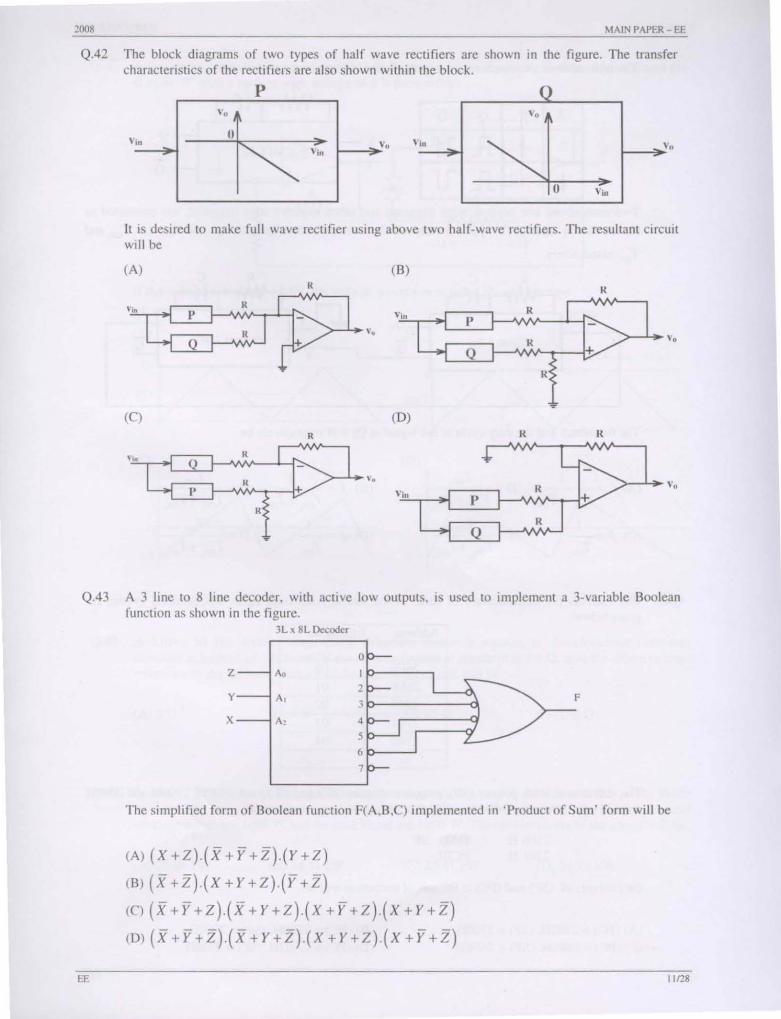
Q.42 The block diagrams of two types of half wave rectifiers are shown in the figure. The transfer characteristics of the rectifiers are also shown within the block.
p
". o
Vin Vin I-_~V" I-_~V"
It is desired to make full wave rectifier using above two half-wave rectifiers. The resu ltant circuit will be
(A) (B) It R
v~ p t2J p ,. Viu R P
Q R ", Q
R
(C) (D) R R R
\ -In It Q
" ". v, I' + R
" in p + R
R Q
Q.43 A 3 line to 8 line decoder, with active low outputs, is used to implement a 3-variable Boolean function as shown in the figure.
EE
3L x 8L Decoder
Z A.
y A, F
X A,
The Simplified form of Boolean function F(A,B,C) implemented in 'Product of Sum' form wi ll be
(A) (X+Z).(X+Y+2') (y+Z)
(B) (X +2').( X + Y + Z).(Y +2')
(e) (x+Y+Z).(X+Y+Z).(X+Y+Z) (X+y+Z)
(D) (x +Y +Z).(X + y +Z)(X +y +Z)(X +Y +2')
1[/28

:!OO8 MAIN PAPER - EE
Q.44 The truth table of a monoshOl shown in the figure is given in the table below:
x y Q
0 t Jl ~ 1 Jl
Q
lJ lJ
x y
R C
Q
TON=0.7 RC Q
Two monoshots, one positive edge lriggered and other negative edge triggered, are connected as
shown in the figure. The pulse widths of the two mono hOI outputs, Q, and Q" are TON, and
TON, respecti vel y.
R C R C
x TON=0.7 RC
+5V TON =0.7 RC Q,
y
The frequency and the duty cycle of the signal at Q, will respectively be
(A) 1 = I D= TONI (B) 1 = 1 ,D
TON!
TON, + TON, ' TON +ToN TONI + TONI TON, + TON, , ,
(C) I=~, D TON (D) 1=_1_. D
TONI , ONI TON, + TON, TON, TON, +ToN,
Q.45 The contents (in Hexadecimal) of some of the memory locations in an 8085A based system arc
EE
given below: Address Contents
.. .. 26FE 00 26FF 01
1700 02 2701 03
2702 04
"
The contents of stack pointer (SP), program counter (PC) and (H,L) are 2700H, 2100H and OOOOH respectively. When the following sequence of 1l1structions are exe~uted,
21ooH: 2101 H:
DAD SP PCHL
the contents of (SP) and (PC) at the end of execution will be
(A) (PC) = 2 I 02H, (SP) = 2700H (e) (PC) = 28ooH, (SP) = 26FEH
(B) (PC) = 27ooH, (SP) = 2700l-l (D) (PC) = 2A02H, (SP) = 2702H
11I~8
2008 MAIN PAPER - EE
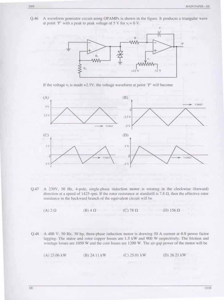
Q.46 A waveform generator circuit using OPAMPs is shown in the figure. It produces a triangular wave at point 'P ' with a peak to peak voltage of 5 V for v; = 0 V.
C
R
'1"
-= + R,
-= R,
+12 V -t2 V
If the voltage v; is made +2.5V, the voltage waveform at point 'P' will become
(A) (B)
5V ----;.. t (sec)
o 25 v -2.5 V .
------;. t (sec) -5 v ··········· , ..
(C) (D)
5V
o
-5 V
Q.47 A 230V, 50 Hz, 4-pole, single-phase induction mOlar is rotating in the clockwise (forward) direction at a speed of 1425 rpm. If the rOlor resistance at standstill is 7.8 11, then the effective rotor resistance in the backward branch of the equivalent circuit will be
(A) 2 11 (B) 4 11 (C) 78 11 (D) 15611
Q.48 A 400 V, 50 Hz, 30 hp, three-phase induction mOlar is drawing 50 A current at 0.8 power factor lagging. The stator and rotor copper losses are 1.5 kW and 900 W respectively. The friction and windage losses are 1050 Wand the core losses are 1200 W. The air-gap power of the motor will be
CA) 23.06 kW (B) 24.11 kW (C) 25.01 kW (D) 26.21 kW
EE 13128
l
2008 MAIN PAI)ER - EE
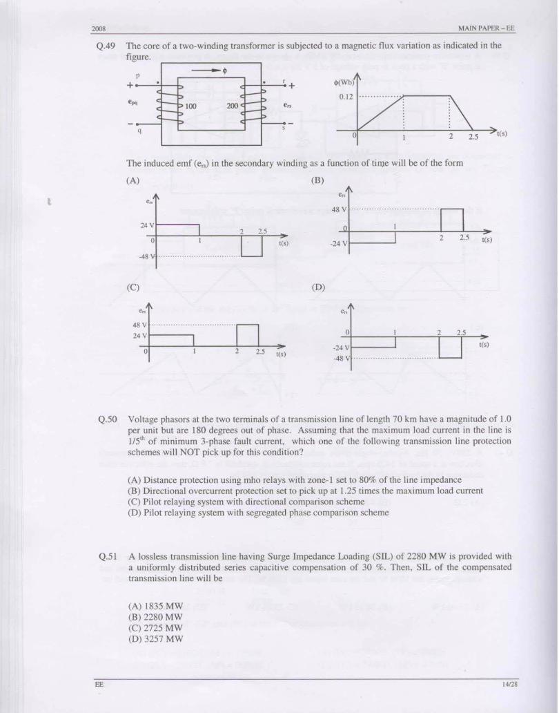
Q.49 The core of a two-winding transformer is subjected to a magnetic flux variation as indicated in the figure
p • • + . . r
200: l- I=>
< p I-~ e < ptOO I-p < I-~ p <
q ,
2.5
+ $(Wb)
epq 0.12 .. ... . ..... . . .. ,... ----".
o 2 ,(, )
The induced emf (e,,) in the secondary wi nding as a function of tiIl)e will be of the form
(A) (B)
24 v 1------, o t(s) -24 vl-----.J ,(,)
(C) (D)
48V .................................. .
24 V o ,(, ) -24 vl-----l
-48 v ······ ...................... . 2 o 2.5 ,(,)
Q.50 Voltage phasors at the two terminals of a transmis ion line of length 70 km have a magnitude of 1.0 per unit but are 180 degrees out of phase. Assuming that the maximum load current in the line is 115'" of minimum 3-phase fault current. which one of the following transmission line protection schemes will NOT pick up for th is cond ition?
(A) Distance protection using mho relays with zone- I set 10 80% of the line impedance (B) Directional overcurrent protection set to pick up at 1.25 times the maximum load current (C) Pilot relaying system with directional comparison scheme (D) Pilot relaying system wi th segregated phase comparison scheme
Q.51 A lossless transmission line having Surge Impedance Loading (SIL) of 2280 MW is provided with a uniformly distributed series capacitive compensation of 30 %. Then. SIL of the compensated transmission line will be
EE
(A) 1835 MW (B) 2280 MW (C) 2725 MW (D) 3257 MW
14128

2008 MAIN PAPER - EE
Q.52 A lossless power system has to serve a load of 250 MW. There are two generators (Oland 02) in the system with cost curves e, and e, respectively defined as follows:
C,(PG,)= PG , +O.055XPG,'
C,(PG,) = 3PG , +O.03xPG2'
where Pc, and PG, are the MW injections from generator 01 and 02 respectively. Then, the minimum cost dispatch will be
(A) POI = 250 MW; Pm = 0 MW (C) POI = 100 MW; Pm = 150 MW
(B) Pc, = 150 MW; Pc, = 100 MW (D) PG , = 0 MW; PG, = 250 MW
Q.53 A lossless single machine infinite bus power system is shown below:
LOL li pu LOL O pu
(,~~dr-L__ __ ~ ~
The synchronous generator transfers 1.0 per unit of power to the infinite bus. The critical clearing time of circuit breaker is 0.28 s. If another identical synchronous generator is connected in parallel to the existing generator and ""ch generator is scheduled to supply 0.5 per unit of power, then the critical clearing time of the circuit breaker will
(A) reduce to 0.14 s (B) reduce but will be more than 0.14 s (e) remain constant at 0.28 s (D) increase beyond 0.28 s
Q.54 Single line diagram of a 4-bus single source distribution system is shown below. Branches e" e"
t; and e4 have equal impedances. The load current values indicated in the figure are in per unit.
l+jO 5+jO
2+jO
Distribution company's policy requires radial system operation with minimum loss. This can be achieved by opening of the branch
(B) e, (e) e3 (D) e.
Q.55 A single phase fully controlled bridge converter supplies a load drawing constant and ripple free load current. If the triggering angle is 30°, the input power factor will be
(A) 0.65 (B) 0.78 (C) 0.85 (D) 0.866
EE 15128

2008 MAIN PAPf:R - EE
Q.56 A si ngle-phase half controlled convener shown in the figure is feeding power to highly inductive load. The convener is operating at a firing angle of 60°.
r '.
1 If the firing pulses are suddenly rcmoved. the steady state voltage (vo) waveform of the convener will become
(A)
.' (C)
' .
.. .. ..
.. ' ......
....
(8)
'.
,'. 2n OJ(
(0)
'.
:'2n WI ,'. 2n wt
Q.57 A :no V, 20 A, 1000 rpm, separately excited dc motor has an armature resistance of 2.5 n. The motor is controlled by a step down chopper with a frequency of 1 kHz. The Input dc voltage to the chopper is 250 V. The duty cycle of the chopper for the mOlor to operate at a speed of 600 rpm delivering the rated torque will be
(A) 0.518 (8) 0.608 (C) 0.852 (0) 0.902
Q.58 A 220 V, 1400 rpm, 40 A separately excited dc motor has an armature resistance of 0.4 n. The motor is fed from a si ngle phase circulating current dual convener with an input ac line voltage of 220 V (rms). The approximate firing angles of the dual converler for motoring operation at 50% of rated torque and 1000 rpm will be
(A) 430. 137° (8) 43°, 47° (0) 39°, 51°
EE t6l18

1008 MAIN PAPER - EE
Q.59 A single phase voltage source inverter is feeding a purely inductive load as shown in the figure.
0.1 II 200 V
'0
The inverter is operated at 50 Hz in ISOo square wave mode. Assume that the load current does not have any dc component. The peak value of the inductor current i. will be
(A) 6.37 A (8) 10 A (C) 20 A (D) 40 A
Q.60 A 400 V, 50 Hz, 4 pole, 1400 rpm, star connected squirrel cage induction motor has the following parameters referred to the stator:
Rc'=I.OQ. X,=Xc' =1.5Q
Neglect stator resistance and core and rotational losses of the motor. The motor is controlled from a 3-phase voltage source inverter with constant V/f control. The stator line-to-line voltage (rms) and frequency to obtain the maximum torque at starting will be:
(A) 20.6 V, 2.7 Hz (8) 133.3 V, 16.7 Hz (C) 266.6 V, 33.3 Hz (D) 323.3 V, 40.3 Hz
Q.61 A single phase fully controlled converter bridge is used for electrical braking of a separately excited dc motor. The dc motor load is represented by an equivalent circuit as shown in the figure.
to
212
150 V
Assume that the load inductance is sufficient to ensure continuous and ripple free load current. The firing angle of the bridge for a load current of 10 = 10 A will be
(A) 44' (8) 51' (el 129' (D) 136'
Q.62 A three phase fully controlled bridge converter is feeding a load drawing a constant and ripple free load current of lOA at a firing angle of 30'. The approximate Total Harmonic Distortion (%THD) and the rrns value of fundamental component of the input current will respectively be
(A) 31% and 6.8 A (8) 31% and 7.S A (C) 66% and 6.8 A (D) 66% and 7.8 A
EE 17128

:!OO8 MAIN PAPER - Et:
Q.63 [n the cirCUIl shown In the figure, the sWllch is operated at a duty cycle of 0.5. A large capacllor is connected across the load. The inductor current is assumed to be continUOUS.
[L=4A L 10 D
20V '5' Load
The average voltage across the load and the average currentlhrough the diode will respectively be
(A) 10 V , 2 A (B) IOV,8A (C) 40V, 2A
Q.64 The transfer function of a linear time invariant system ,s given as [
G(s) = s' + 3s + 2
(D) 40 V, 8 A
The steady state value of the output of this system for a unit impulse input applied at time instant C = I will be
(A) 0 (B) 0.5 (C) I
Q.65 The transfer functions of two compensators are given below:
c = 10 (s + I) C , (s + [0)' ,
Which one of the following statements is correct?
s+IO
10 (s+ I)
(A) C, is a lead compensator and C, is a lag compensator
(B) C, is a lag compensator and C, is a lead compensator
(C) Both C, and C, are lead compensators
(D) Both C, and C, are lag compensators
(0) 2
Q.66 The asymptotic Bode magnitude plot of a minimum phase transfer function is shown in the fi gure:
EE
IG{jw)1 (dB)
o w (radls) (log scale)
-20 .. · .................... ......... ...... . .. . '-- 0 dB/decade
This transfer function has
(A) Three poles and one zero (e) Two poles and two zeros
(B) Two poles and one zero (D) One pole and two zeros
' 8128
2008 MAIN PAPER - EE
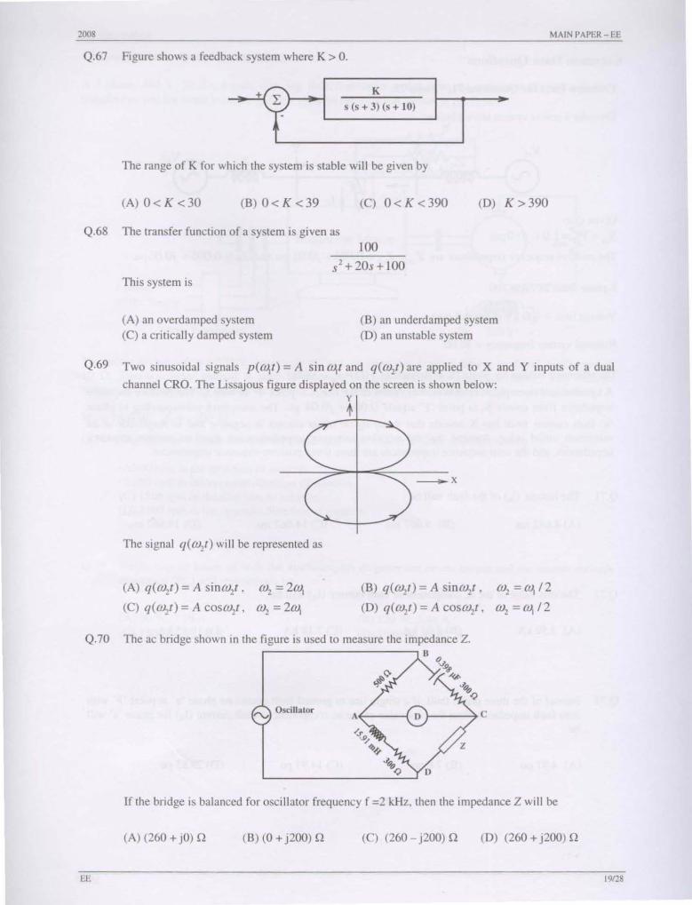
Q.67 Figure shows a feedback system where K > O.
· +0L-....-- • =-_K-----'~I L ~(s+lO) . _
The range of K for which the system is stable will be given by
(A) 0< K <30 (B) 0< K <39 (C) 0< K <390 (D) K >390
Q.68 The transfer function of a system is given as
100
s'+ 20s + 100 This system is
(A) an overdamped system (C) a critically damped system
(B) an underdamped system (D) an unstable system
Q.69 Two sinusoidal signals p(OJ, I ) = A sin OJ,I and q(w,t) are applied to X and Y inputs of a dual
channel eRO. The Lissajous figure displayed on the screen is shown below:
The signal q(W,I) will be represented as
(A) q(W,I) = A sinw,l ,
(C) q(OJ,t) = A COSW,I,
w, =2w, w, =2w,
y
1
__ x
(B) q(w,L) = A sinw,t ,
(D) q(OJ,I) = A COSW,I ,
W, = w,/2 w,=0J,/2
Q.70 The ac bridge shown in the figure is used to measure the impedance Z.
rv Oscill ator A~--{ }-_~ c
If the bridge is balanced for oscillator frequency f =2 kHz, then the impedance Z will be
(A) (260 + jO) Q (B) (0 + j200) Q (C) (260 - j200) Q (D) (260 + j200) Q
EE 19128

::!008 MAIN PAPER - FE
Common Data Questions
Common Data for Questions 7l, 72 and 73:
Consider a power system shown below:
Given that:
V. I = V" = 1.0 + jO.O pu;
The positive sequence impedances are Z,I = Z" = 0.001 + jO.O I pu and ZL = 0.006 + jO.06 pu.
3-phase Base MV A = 100
Voltage base = 400 kV (Line to Line)
Nominal system frequency = 50 Hz
The reference voltage for phase 'a' is defined as vCr) = Vm cos(ax).
A symmetrical three phase fault occurs at centre of the line. i.e. point 'F' at time to' The positive sequence impedance from source SI to point 'F' equals 0.004+ jO.04 pu. The waveform corresponding 10 phase
'a' fault current from bus X reveals that decaying dc offset current is negative and in magnitude at its maximum initial value. Assume that the negative sequence impedances are equal to positive sequence impedances, and the zero sequence impedances are three times positive s~quence impedances.
Q.71 The instant (to) of the fault will be
(A) 4.682 ms (B) 9.667 ms (C) 14.667 ms (D) 19.667 ms
Q.72 The rms value of the ac component of fault current (Ix) will be
(A) 3.59 kA (B) 5.07 kA (C)7.18kA (D)10.15kA
Q.73 Instead of the three phase fault, if a single line to ground fau lt occurs on phase 'a' at point 'F' with zero fault impedance, then the rms value of the ac component of fault current (Ix) for phase 'a' will be
(A) 4.97 pu (B)7.0 pu (C) 14.93 pu (D) 29.85 pu
EE 201::!8
.. J008 MAINPAPER-EE
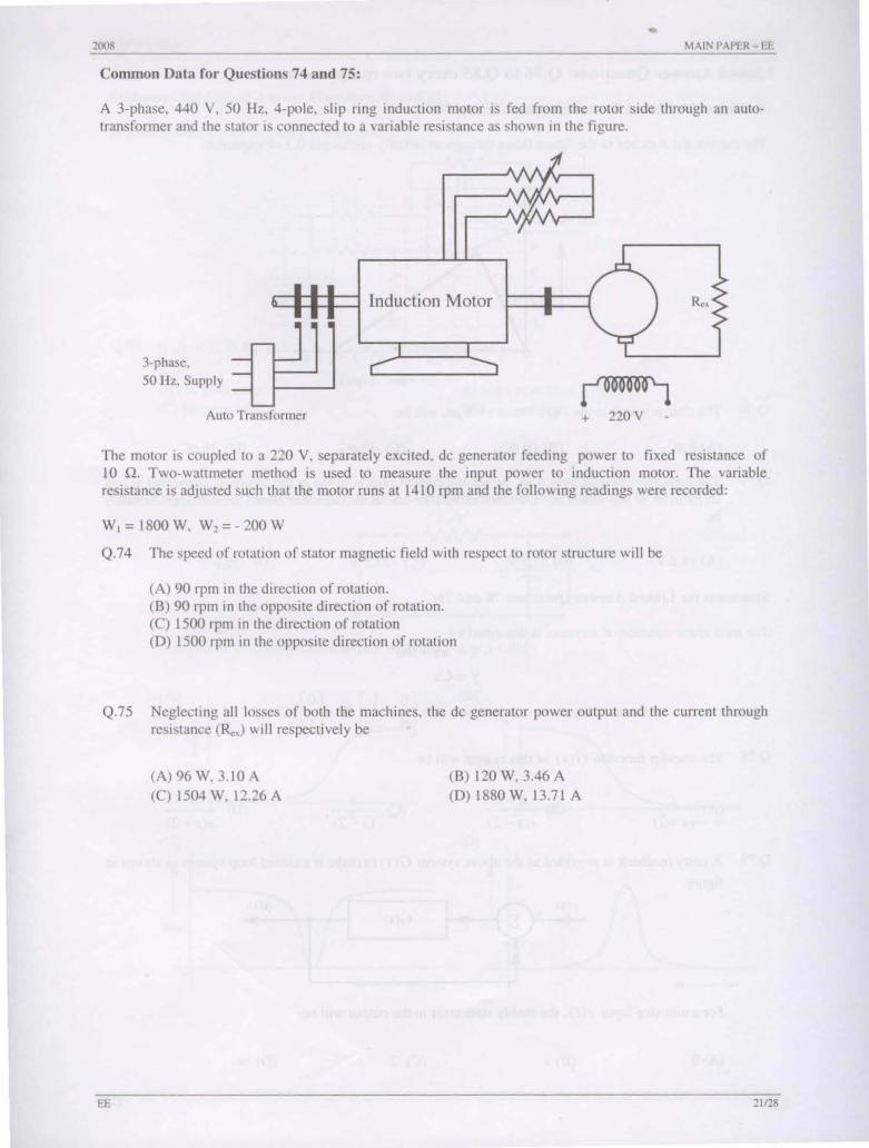
Common Data for Questions 74 and 75:
A 3-phase, 440 Y, 50 Hz, 4-pole, slip ring induction motor is fed from the rotor side through an autotransformer and the stator is connected to a variable resistance as shown in the figure.
cl:l~~ Induction Motor
3-phase, 50 Hz, Supply
~ Auto Transformer + 220Y
The motor is coupled to a 220 Y, separately excited, de generator feeding power to fixed resistance of !o Q. Two-wattmeter method is used to measure the input power to induction motor. The variable resistance is adjusted such that the motor runs at 14!O rpm and the following readings were recorded:
W, = 1800W, W,=-200W
Q.74 The speed of rotation of stator magnetic field with respect to rotor structure will be
(A) 90 rpm in the direction of rotation. (B) 90 rpm in the opposite direction of rotation. (C) 1500 rpm in the direction of rotation (D) 1500 rpm in the opposite direction of rotation
Q.75 Neglecting all losses of both the machines, the de generator power output and the current through resistance (Rex) will respectively be
EE
(A) 96 W, 3.10 A
(C) 1504 W, 12.26 A (B) 120 W, 3.46 A (D) 1880 W, 13.71 A
2tt:!8
• 2008 MAIN PAPER - EE
Linked Answer Questions: Q.76 to Q.85 carry two marks each.
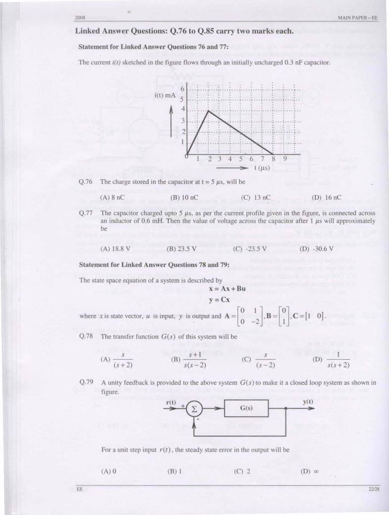
Statement for Linked Answer Questions 76 and 77:
The current i(l) sketched in the figure flows through an initially uncharged 0.3 nF capacitor.
6: itt) mA 5
! 4
3
· . . · .. · '. . . .. : .... ;- ... : .... ;- ... : .... : ... . : .... : .. . . . . · . . . . . .
:. ........ :. ........ : ....... .. - .. · . . . . . . · . .. . · . . . ; ... .; .... ; ... .; .... ~ ... .; ...
23456789 ---;,0 ... - t (ft s)
Q.76 The charge stored in the capacitor at t = 5 /ls, will be
(A) 8 nC (8) 10 nC (C) 13 nC (D) 16 nC
Q.77 The capacitor charged upto 5 /lS , as per the current profile given in the figure, is connected across an inductor of 0.6 mHo Then the value of voltage across the capacitor after I /ls will approximately be
(A) 18.8 V (8) 23.5 V (C) -23.5 V (D) -30.6 V
Statement for Linked Answer Questions 78 and 79:
The state space equation of a system is described by x = Ax+Bu
y=Cx
where x is state vector, u is input. y is output and A = [~ ~2]' B = [~], C = [1 0].
Q.78 The transfer function G(s) of this system will be
(A) (s: 2) (8) s + I
s(s - 2) (C) (S~2) (D) s(s + 2)
Q.79 A unity feedback is provided to the above system G(s) to make it a closed loop system as shown in
figure.
'~ .~ yet) ... G(s)
I 30
For a unit step input r(t) , the steady state error in the output will be
(A) 0 (8 ) I (C) 2 (D) aJ
EE 22128

2008
Statement for Linked Answer Questions 80 and 81:
A general filter circuit is shown in the figure:
c
'. >--+---
Q.80 If R, = R, = RA and R, = R, = R. ' the circuit acts as a
Q.81
EE
(A) all pass filter (C) high pass filter
(B) band pass filter (D) low pass filter
The output of the filter in Q.80 is given to the circuit shown in figure: RAI2
VI, Qa-----------'j WN'----, ft--<>j ,
The gain vs frequency characteristic of the output (vo) will be
(A) (B)
I 1 G., Gain
0 w_ 0
(e) (0)
i i Gain G:.in
0 0 ~
MAIN PAPER - EE
(J)_
w---;.~
nns

2008 MAIN PAPER - EE
Statement for Linked Answer Questions 82 and 83:
A 240 V, dc shunt motor draws 15 A while supplying the rated load at a speed of 80 rad/s. The armature resistance is 0.5 n and the field winding resistance is 80 n.
Q.82 The net voltage across the armature resistance at the time of plugging will be
CA) 6 V (B) 234 V (C) 240 V (D) 474 V
Q.83 The external resistance to be added in the armature circuit to limit the armature current to 125% of its rated value is
CA) 31.1 n (B) 31.9 n (C) 15.1 n (0) 15.9 n
Statement for Linked Answer Questions 84 and 85:
A synchronous motor is connected to an infinite bus at 1.0 pu voltage and draws 0.6 pu current at unity power factor. Its synchronous reactance is 1.0 pu and resistance is negligible.
Q.84 The excitation voltage (E) and load angle (0) will respectively be
(A) 0.8 pu and 36.86° lag (e) 1.17 pu and 30.96° lead
(B) 0.8 pu and 36.86° lead (D) 1.17 pu and 30.96° lag
Q.85 Keeping the excitation voltage same, the load on the motor is increased such that the motor current increases by 20%. The operating power factor will become
(A) 0.995 lagging (B) 0.995 leading (C) 0.79\ lagging (0) 0.848 leading
END OF THE QUESTION PAPER
FE 24/28