Embed Size (px)
Citation preview

GATE EE2010
Brought to you by: Nodia and Company Visit us at: www.nodia.co.in
PUBLISHING FOR GATE
Q.1 - 25 carry one mark each.
MCQ 1.1 The value of the quantity P , where P xe dxx
0
1
= # , is equal to
(A) 0 (B) 1
(C) e (D) 1/e
SOL 1.1 Hence (B) is correct option.
P xe dxx
0
1= #
( )dxd x e dx dxx
0
1
0
1x e dxx= − :6 D@# ##
( )e dx1 x
0
1
0
1xex= −6 @ #
( 0)e1
0
1ex
= − −6 @
[ ]e e e1 1 0= − −
1=
MCQ 1.2 Divergence of the three-dimensional radial vector field r is(A) 3 (B) /r1
(C) i j k+ +t t t (D) 3( )i j k+ +t t t
SOL 1.2 Hence (A) is correct option. Radial vector r x y zi j k= + +t t t
Divergence r4$=
x y z
x y zi j k i j k:22
22
22= + + + +t t t t t t
c _m i
xx
yy
zz
22
22
22= + +
Page 2 GATE EE 2010 www.gatehelp.com
Brought to you by: Nodia and Company Visit us at: www.nodia.co.in
PUBLISHING FOR GATE
1 1 1= + + 3=
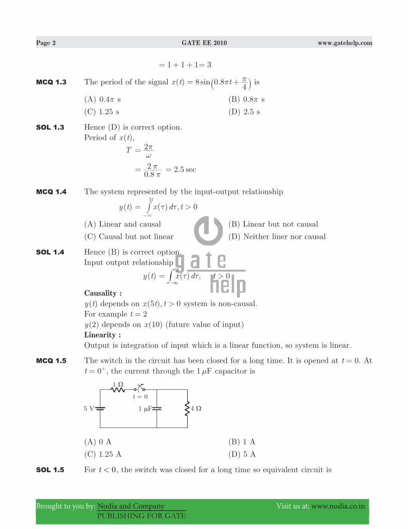
MCQ 1.3 The period of the signal ( ) 0.8sinx t t84
π π= +` j is
(A) 0.4π s (B) 0.8π s
(C) 1.25 s (D) 2.5 s
SOL 1.3 Hence (D) is correct option.Period of ( )x t ,
T 2ωπ=
.0 82
ππ= . sec2 5=
MCQ 1.4 The system represented by the input-output relationship
( )y t ( ) ,x d t 0>t5
τ τ=3−
#
(A) Linear and causal (B) Linear but not causal
(C) Causal but not linear (D) Neither liner nor causal
SOL 1.4 Hence (B) is correct option.Input output relationship
( )y t ( ) ,x d t 0>t5
τ τ=3-
#
Causality :( )y t depends on ( ),x t t5 0> system is non-causal.
For example t 2=( )y 2 depends on ( )x 10 (future value of input)
Linearity :Output is integration of input which is a linear function, so system is linear.
MCQ 1.5 The switch in the circuit has been closed for a long time. It is opened at .t 0= At t 0= +, the current through the 1 Fμ capacitor is
(A) 0 A (B) 1 A
(C) 1.25 A (D) 5 A
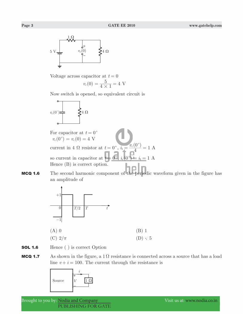
SOL 1.5 For t 0< , the switch was closed for a long time so equivalent circuit is
Page 3 GATE EE 2010 www.gatehelp.com
Brought to you by: Nodia and Company Visit us at: www.nodia.co.in
PUBLISHING FOR GATE
Voltage across capacitor at t 0=
(0)vc 44 15#
= = V
Now switch is opened, so equivalent circuit is
For capacitor at 0t = +
(0 )vc+ (0) 4vc= = V
current in 4 Ω resistor at t 0= +, (0 )
iv
4 1c1 = =
+
A
so current in capacitor at t 0= +, ( )i i0 1c 1= =+ AHence (B) is correct option.
MCQ 1.6 The second harmonic component of the periodic waveform given in the figure has an amplitude of
(A) 0 (B) 1
(C) /2 π (D) 5
SOL 1.6 Hence ( ) is correct Option
MCQ 1.7 As shown in the figure, a 1 Ω resistance is connected across a source that has a load line v i 100+ = . The current through the resistance is
Page 4 GATE EE 2010 www.gatehelp.com
Brought to you by: Nodia and Company Visit us at: www.nodia.co.in
PUBLISHING FOR GATE
(A) 25 A (B) 50 A
(C) 100 A (C) 200 A
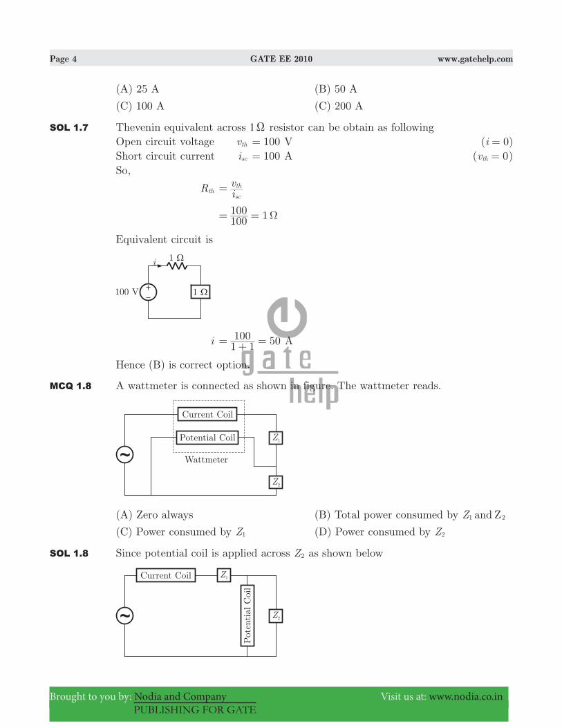
SOL 1.7 Thevenin equivalent across 1 X resistor can be obtain as followingOpen circuit voltage vth 100= V ( 0)i =Short circuit current isc 100= A ( 0vth = )So,
Rth ivsc
th=
1100100 Ω= =
Equivalent circuit is
i 501 1100= + = A
Hence (B) is correct option.
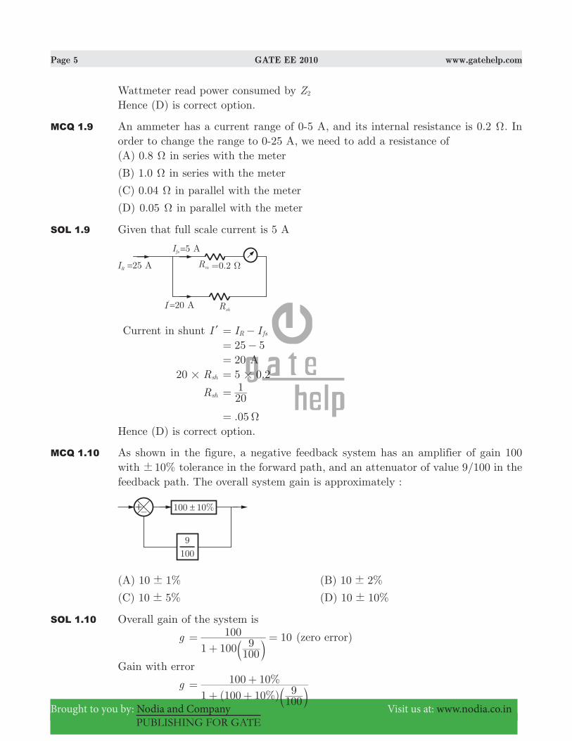
MCQ 1.8 A wattmeter is connected as shown in figure. The wattmeter reads.
(A) Zero always (B) Total power consumed by Z and Z1 2
(C) Power consumed by Z1 (D) Power consumed by Z2
SOL 1.8 Since potential coil is applied across Z2 as shown below
Page 5 GATE EE 2010 www.gatehelp.com
Brought to you by: Nodia and Company Visit us at: www.nodia.co.in
PUBLISHING FOR GATE
Wattmeter read power consumed by Z2
Hence (D) is correct option.
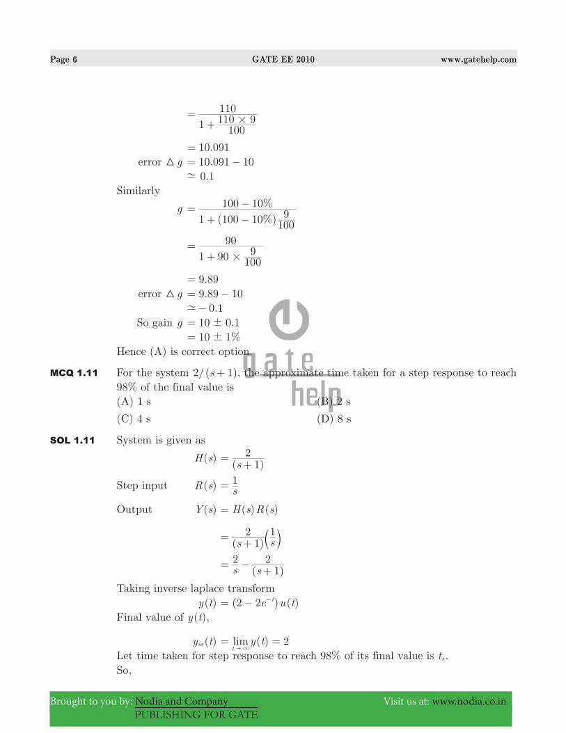
MCQ 1.9 An ammeter has a current range of 0-5 A, and its internal resistance is 0.2 Ω. In order to change the range to 0-25 A, we need to add a resistance of(A) 0.8 Ω in series with the meter
(B) 1.0 Ω in series with the meter
(C) 0.04 Ω in parallel with the meter
(D) 0.05 Ω in parallel with the meter
SOL 1.9 Given that full scale current is 5 A
Current in shunt Il I IR fs= − 25 5= − 20= A R20 sh# .5 0 2#=
Rsh 201=
.05 Ω=Hence (D) is correct option.
MCQ 1.10 As shown in the figure, a negative feedback system has an amplifier of gain 100 with %10! tolerance in the forward path, and an attenuator of value 9/100 in the feedback path. The overall system gain is approximately :
(A) %10 1! (B) %10 2!
(C) %10 5! (D) %10 10!
SOL 1.10 Overall gain of the system is
g 101 100 100
9100=
+=
b l (zero error)
Gain with error
g ( %)
%1 100 10 100
9100 10=
+ ++
b l
Page 6 GATE EE 2010 www.gatehelp.com
Brought to you by: Nodia and Company Visit us at: www.nodia.co.in
PUBLISHING FOR GATE
110 91 100
110#
=+
.10 091= error g3 .10 091 10= − .0 1-
Similarly
g ( %)
%1 100 10 100
9100 10=
+ −−
1 90 100
990
#
=+
.9 89= error g3 .9 89 10= − .0 1-− So gain g 10 .0 1!= %10 1!=Hence (A) is correct option.
MCQ 1.11 For the system /( )s2 1+ , the approximate time taken for a step response to reach 98% of the final value is(A) 1 s (B) 2 s
(C) 4 s (D) 8 s
SOL 1.11 System is given as
( )H s ( )s 1
2= +
Step input ( )R s s1=
Output ( )Y s ( ) ( )H s R s=
( )
1s s1
2= + b l
( )s s
21
2= − +
Taking inverse laplace transform ( )y t ( ) ( )e u t2 2 t= − −
Final value of ( )y t ,
( )y tss ( )limy t 2t
= ="3
Let time taken for step response to reach 98% of its final value is ts .So,
Page 7 GATE EE 2010 www.gatehelp.com
Brought to you by: Nodia and Company Visit us at: www.nodia.co.in
PUBLISHING FOR GATE
2 2e ts− − .2 0 98#= .02 e ts= −
ts ln50= .3 91= sec.Hence (C) is correct option.
MCQ 1.12 If the electrical circuit of figure (B) is an equivalent of the coupled tank system of figure (A), then
(A) A, B are resistances and C, D capacitances
(B) A, C are resistances and B, D capacitances
(C) A, B are capacitances and C, D resistances
(D) A, C are capacitances and B, D resistances
SOL 1.12 Hence ( ) is correct Option
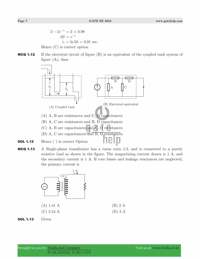
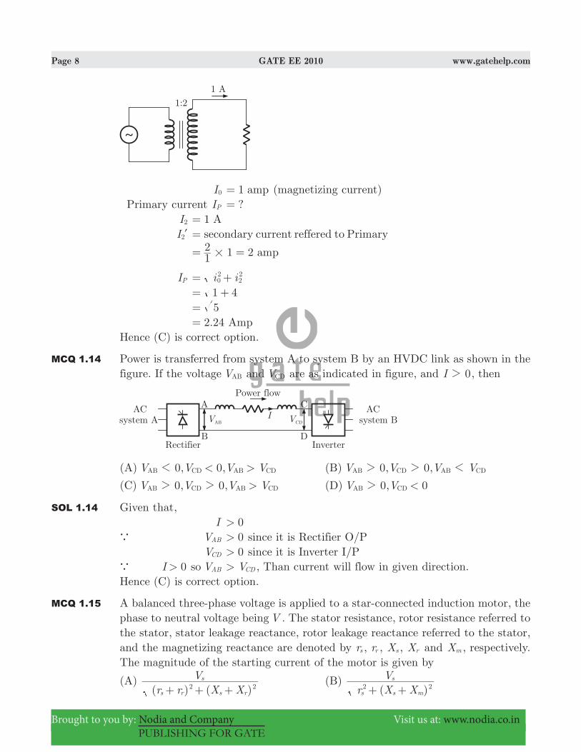
MCQ 1.13 A Single-phase transformer has a turns ratio 1:2, and is connected to a purely resistive load as shown in the figure. The magnetizing current drawn is 1 A, and the secondary current is 1 A. If core losses and leakage reactances are neglected, the primary current is
(A) 1.41 A (B) 2 A
(C) 2.24 A (D) 3 A
SOL 1.13 Given
Page 8 GATE EE 2010 www.gatehelp.com
Brought to you by: Nodia and Company Visit us at: www.nodia.co.in
PUBLISHING FOR GATE
I0 1 amp= (magnetizing current) Primary current IP ?= I2 1 A= I2l secondary current reffered to Primary=
1 212 amp#= =
IP i i02
22= +
1 4= + 5= 2.24 Amp=Hence (C) is correct option.
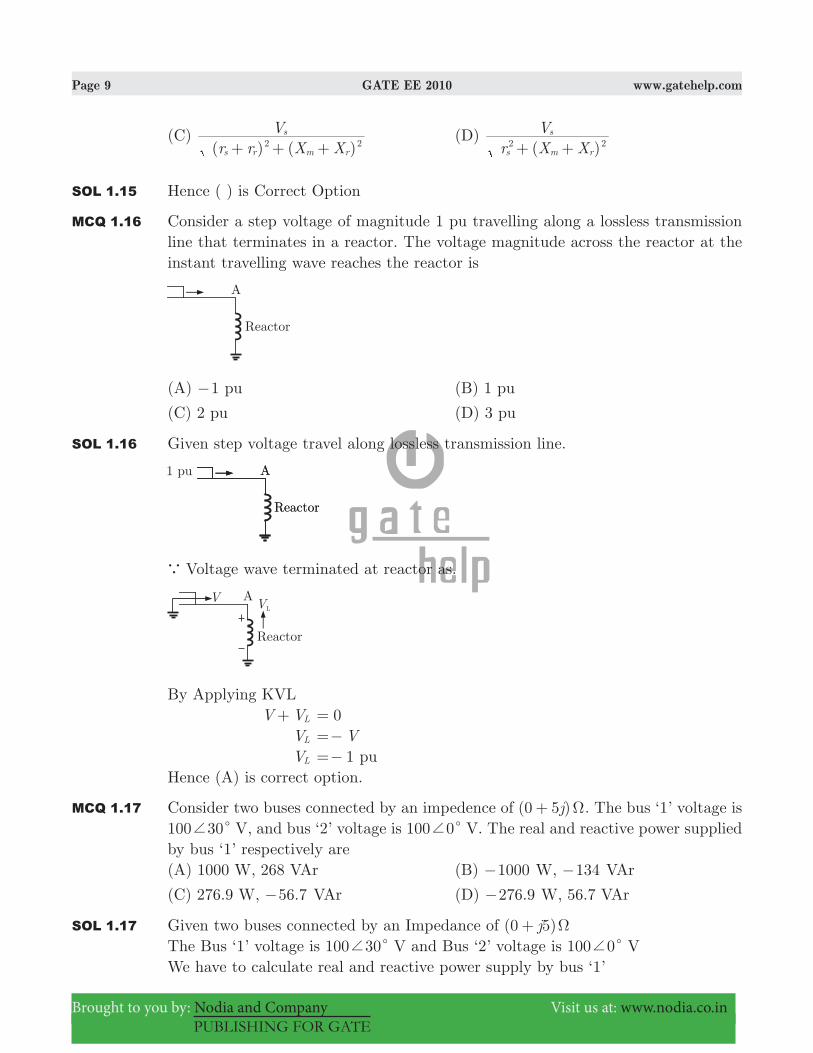
MCQ 1.14 Power is transferred from system A to system B by an HVDC link as shown in the figure. If the voltage VAB and VCD are as indicated in figure, and I 02 , then
(A) 0, 0,V V V V< >AB CD AB CD1 (B) 0, 0,V V V VAB CD AB CD2 2 1
(C) 0, 0,V V V V>AB CD AB CD2 2 (D) 0, 0V V <AB CD2
SOL 1.14 Given that, I 0>a VAB 0> since it is Rectifier O/P VCD 0> since it is Inverter I/Pa I 0> so VAB V> CD , Than current will flow in given direction.Hence (C) is correct option.
MCQ 1.15 A balanced three-phase voltage is applied to a star-connected induction motor, the phase to neutral voltage being V . The stator resistance, rotor resistance referred to the stator, stator leakage reactance, rotor leakage reactance referred to the stator, and the magnetizing reactance are denoted by rs , rr , Xs , Xr and Xm , respectively. The magnitude of the starting current of the motor is given by
(A) ( ) ( )r r X X
Vs r s r
s2 2+ + +
(B) ( )r X XV
s s m
s2 2+ +
Page 9 GATE EE 2010 www.gatehelp.com
Brought to you by: Nodia and Company Visit us at: www.nodia.co.in
PUBLISHING FOR GATE
(C) ( ) ( )r r X X
Vs r m r
s2 2+ + +
(D) ( )r X XV
s m r
s2 2+ +
SOL 1.15 Hence ( ) is Correct Option
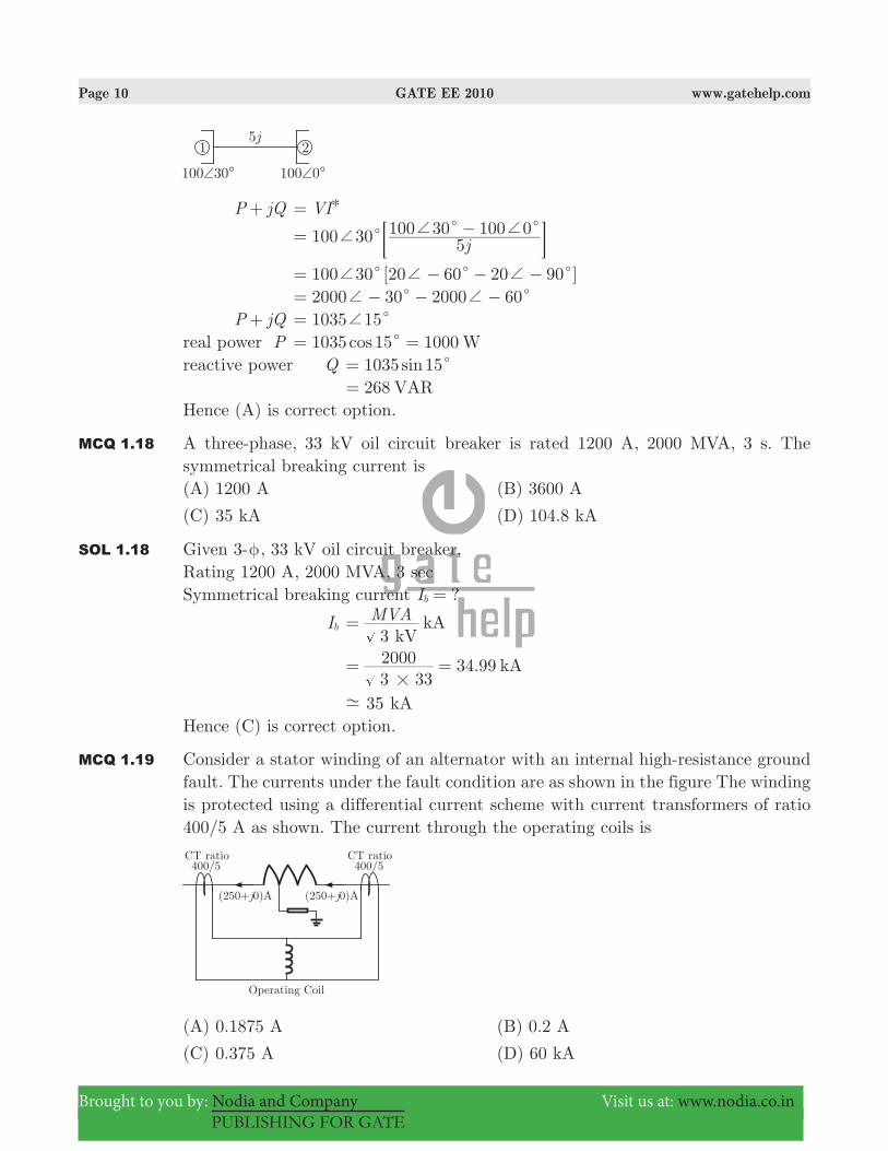
MCQ 1.16 Consider a step voltage of magnitude 1 pu travelling along a lossless transmission line that terminates in a reactor. The voltage magnitude across the reactor at the instant travelling wave reaches the reactor is
(A) 1− pu (B) 1 pu
(C) 2 pu (D) 3 pu
SOL 1.16 Given step voltage travel along lossless transmission line.
a Voltage wave terminated at reactor as.
By Applying KVL V VL+ 0= VL V=− VL 1=− puHence (A) is correct option.
MCQ 1.17 Consider two buses connected by an impedence of ( )j0 5 Ω+ . The bus ‘1’ voltage is 100 30c+ V, and bus ‘2’ voltage is 100 0c+ V. The real and reactive power supplied by bus ‘1’ respectively are(A) 1000 W, 268 VAr (B) 1000− W, 134− VAr
(C) 276.9 W, .56 7− VAr (D) .276 9− W, 56.7 VAr
SOL 1.17 Given two buses connected by an Impedance of ( )j0 5 Ω+The Bus ‘1’ voltage is 100 30c+ V and Bus ‘2’ voltage is 100 0c+ VWe have to calculate real and reactive power supply by bus ‘1’
Page 10 GATE EE 2010 www.gatehelp.com
Brought to you by: Nodia and Company Visit us at: www.nodia.co.in
PUBLISHING FOR GATE
P jQ+ VI= )
j100 30 5100 30 100 0c c c+ + += −; E
100 30 [20 60 20 90 ]c c c+ + += − − − 2000 30 200 600c c+ += − − − P jQ+ 1035 15c+=real power P 1035 15 1000cos Wc= =reactive power Q 1035 15sin c= 268 VAR=Hence (A) is correct option.
MCQ 1.18 A three-phase, 33 kV oil circuit breaker is rated 1200 A, 2000 MVA, 3 s. The symmetrical breaking current is(A) 1200 A (B) 3600 A
(C) 35 kA (D) 104.8 kA
SOL 1.18 Given 3-φ, 33 kV oil circuit breaker.Rating 1200 A, 2000 MVA, 3 sec Symmetrical breaking current ?Ib =
Ib MVA3 kV
kA=
34.993 332000 kA#
= =
35- kAHence (C) is correct option.
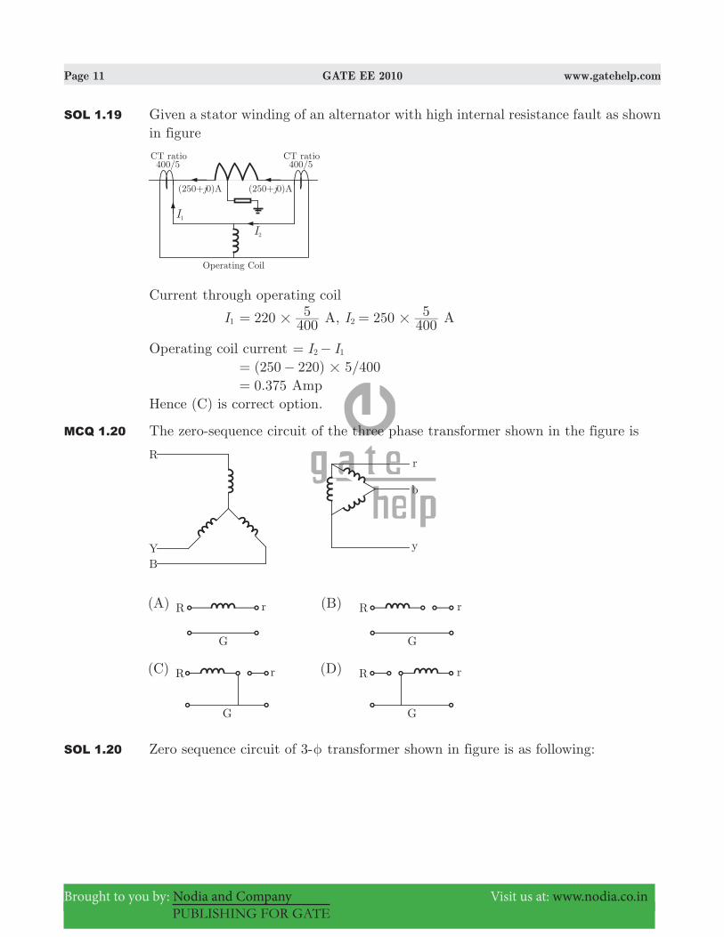
MCQ 1.19 Consider a stator winding of an alternator with an internal high-resistance ground fault. The currents under the fault condition are as shown in the figure The winding is protected using a differential current scheme with current transformers of ratio 400/5 A as shown. The current through the operating coils is
(A) 0.1875 A (B) 0.2 A
(C) 0.375 A (D) 60 kA
Page 11 GATE EE 2010 www.gatehelp.com
Brought to you by: Nodia and Company Visit us at: www.nodia.co.in
PUBLISHING FOR GATE
SOL 1.19 Given a stator winding of an alternator with high internal resistance fault as shown in figure
Current through operating coil
I1 220 4005
#= A, I 250 4005
2 #= A
Operating coil current I I2 1= − ( ) /250 220 5 400#= − .0 375= AmpHence (C) is correct option.
MCQ 1.20 The zero-sequence circuit of the three phase transformer shown in the figure is
SOL 1.20 Zero sequence circuit of 3-φ transformer shown in figure is as following:
Page 12 GATE EE 2010 www.gatehelp.com
Brought to you by: Nodia and Company Visit us at: www.nodia.co.in
PUBLISHING FOR GATE
No option seems to be appropriate but (C) is the nearest.Hence (C) is correct option.
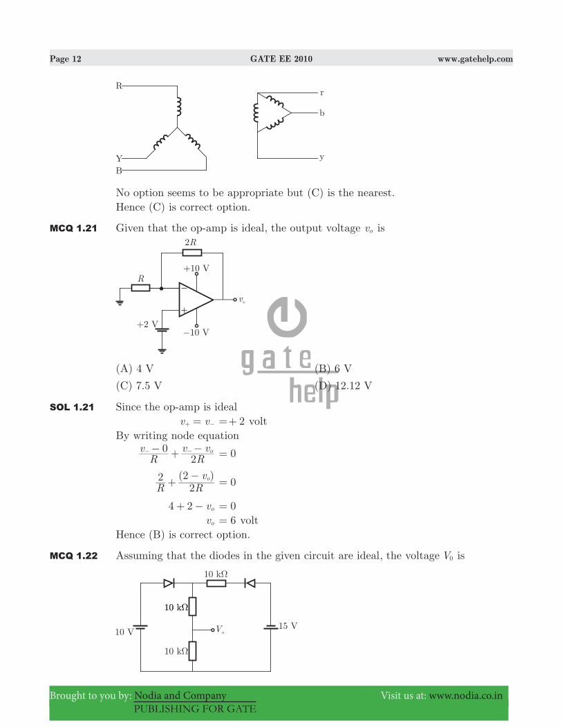
MCQ 1.21 Given that the op-amp is ideal, the output voltage vo is
(A) 4 V (B) 6 V
(C) 7.5 V (D) 12.12 V
SOL 1.21 Since the op-amp is ideal v v=+ − 2=+ voltBy writing node equation
Rv
Rv v0
2o− + −− − 0=
( )
R Rv2
22 o+ −
0=
4 2 vo+ − 0= vo 6= voltHence (B) is correct option.
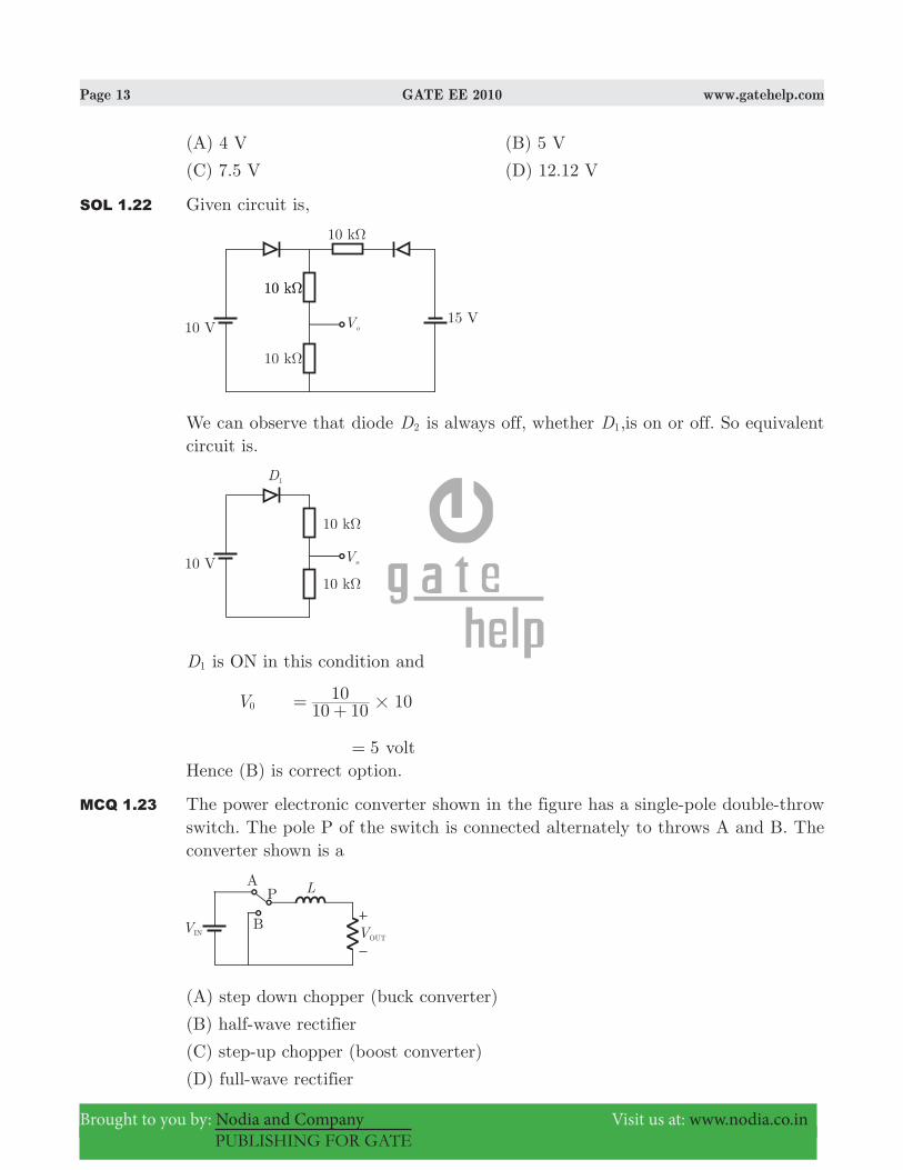
MCQ 1.22 Assuming that the diodes in the given circuit are ideal, the voltage V0 is
Page 13 GATE EE 2010 www.gatehelp.com
Brought to you by: Nodia and Company Visit us at: www.nodia.co.in
PUBLISHING FOR GATE
(A) 4 V (B) 5 V
(C) 7.5 V (D) 12.12 V
SOL 1.22 Given circuit is,
We can observe that diode D2 is always off, whether D1,is on or off. So equivalent circuit is.
D1 is ON in this condition and
V0 10 1010 10#= +
5= voltHence (B) is correct option.
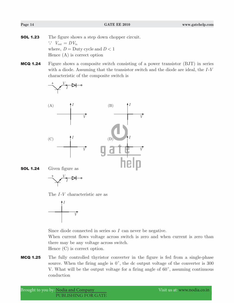
MCQ 1.23 The power electronic converter shown in the figure has a single-pole double-throw switch. The pole P of the switch is connected alternately to throws A and B. The converter shown is a
(A) step down chopper (buck converter)
(B) half-wave rectifier
(C) step-up chopper (boost converter)
(D) full-wave rectifier
Page 14 GATE EE 2010 www.gatehelp.com
Brought to you by: Nodia and Company Visit us at: www.nodia.co.in
PUBLISHING FOR GATE
SOL 1.23 The figure shows a step down chopper circuit.a Vout DVin=where, 1D DDuty cycle and <=Hence (A) is correct option
MCQ 1.24 Figure shows a composite switch consisting of a power transistor (BJT) in series with a diode. Assuming that the transistor switch and the diode are ideal, the I -V characteristic of the composite switch is
SOL 1.24 Given figure as
The I -V characteristic are as
Since diode connected in series so I can never be negative.When current flows voltage across switch is zero and when current is zero than there may be any voltage across switch.Hence (C) is correct option.
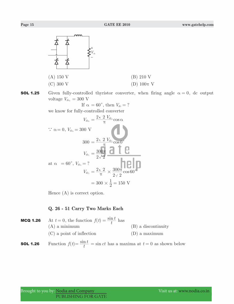
MCQ 1.25 The fully controlled thyristor converter in the figure is fed from a single-phase source. When the firing angle is 0c, the dc output voltage of the converter is 300 V. What will be the output voltage for a firing angle of 60c, assuming continuous conduction
Page 15 GATE EE 2010 www.gatehelp.com
Brought to you by: Nodia and Company Visit us at: www.nodia.co.in
PUBLISHING FOR GATE
(A) 150 V (B) 210 V
(C) 300 V (D) 100π V
SOL 1.25 Given fully-controlled thyristor converter, when firing angle 0α = , dc output voltage Vdc0 300 V= If α 60c= , then ?Vdc =we know for fully-controlled converter
Vdc0 cosV2 2 dc1
π α=
a α 0= , 300Vdc0 = V
300 0cosV2 2 dc1 cπ=
Vdc1 2 2300π=
at α 60c= , ?Vdc2 =
Vdc2 cos2 22 2300 60# cπ
π=
300 15021 V#= =
Hence (A) is correct option.
Q. 26 - 51 Carry Two Marks Each
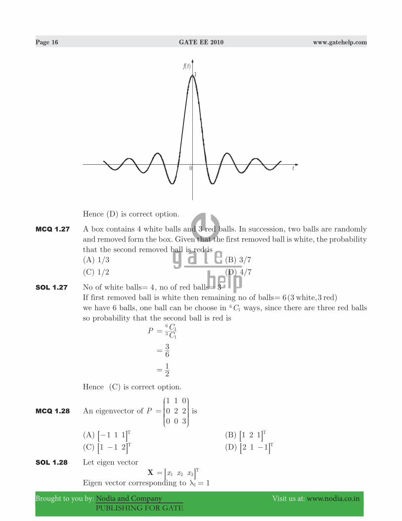
MCQ 1.26 At t 0= , the function ( ) sinf t tt= has
(A) a minimum (B) a discontinuity
(C) a point of inflection (D) a maximum
SOL 1.26 Function ( )f t sint
t= sinct= has a maxima at 0t = as shown below
Page 16 GATE EE 2010 www.gatehelp.com
Brought to you by: Nodia and Company Visit us at: www.nodia.co.in
PUBLISHING FOR GATE
Hence (D) is correct option.
MCQ 1.27 A box contains 4 white balls and 3 red balls. In succession, two balls are randomly and removed form the box. Given that the first removed ball is white, the probability that the second removed ball is red is(A) 1/3 (B) 3/7
(C) 1/2 (D) 4/7
SOL 1.27 No of white balls 4= , no of red balls 3=If first removed ball is white then remaining no of balls 6(3 ,3white red)=we have 6 balls, one ball can be choose in C6
1 ways, since there are three red balls so probability that the second ball is red is
P CC
31
61=
63=
21=
Hence (C) is correct option.
MCQ 1.28 An eigenvector of P 100
120
023
=
J
L
KKK
N
P
OOO is
(A) 1 1 1 T−8 B (B) 1 2 1 T8 B
(C) 1 1 2 T−8 B (D) 2 1 1 T−8 B
SOL 1.28 Let eigen vector X x x x1 2 3
T= 8 B
Eigen vector corresponding to 11λ =

Page 17 GATE EE 2010 www.gatehelp.com
Brought to you by: Nodia and Company Visit us at: www.nodia.co.in
PUBLISHING FOR GATE
A I X1λ−8 B 0=
xxx
000
110
022
1
2
3
R
T
SSSS
R
T
SSSS
V
X
WWWW
V
X
WWWW
000
=
R
T
SSSS
V
X
WWWW
x2 0= x x2 02 3+ = x 03& = (not given in the option)Eigen vector corresponding to 22λ = A I X2λ−8 B 0=
xxx
100
100
021
1
2
3
−R
T
SSSS
R
T
SSSS
V
X
WWWW
V
X
WWWW
000
=
R
T
SSSS
V
X
WWWW
x x1 2− + 0= 2 0x3 = x 03& = (not given in options.)Eigen vector corresponding to 33λ = A I X3λ−8 B 0=
xxx
200
11
0
020
1
2
3
−−
R
T
SSSS
R
T
SSSS
V
X
WWWW
V
X
WWWW
000
=
R
T
SSSS
V
X
WWWW
x x2 1 2− + 0= x x22 3− + 0=
Put ,x x1 21 2= = and x 13 =So Eigen vector
X xxx
1
2
3
=
R
T
SSSS
V
X
WWWW
121
1 2 1 T= =
R
T
SSSS
8
V
X
WWWW
B
Hence (B) is correct option.
MCQ 1.29 For the differential equation dtd x
dtdx x6 8 02
2
+ + = with initial conditions ( )x 0 1=
and dtdx 0
t 0=
=, the solution is
(A) ( ) 2x t e et t6 2= −− − (B) ( ) 2x t e et t2 4= −− −
(C) ( ) 2x t e et t6 4=− +− − (D) ( ) 2x t e et t2 4= +− −
SOL 1.29 Hence (B) is correct option.
8dtd x
dtdx x62
2
+ + 0=
Taking Laplace transform (with initial condition) on both sides ( ) ( ) ' ( ) [ ( ) ( )] ( )s X s sx x sX s x X s0 0 6 0 82 − − + − + 0=
Page 18 GATE EE 2010 www.gatehelp.com
Brought to you by: Nodia and Company Visit us at: www.nodia.co.in
PUBLISHING FOR GATE
( ) ( ) [ ( ) ] ( )s X s s sX s X s1 0 6 1 82 − − + − + 0= ( ) [ ]X s s s s6 8 62 + + − − 0=
( )X s ( )
( )s s
s6 8
62=+ +
+
By partial fraction
( )X s s s22
41= + − +
Taking inverse Laplace transform ( )x t ( )e e2 t t2 4= −− −
MCQ 1.30 For the set of equations, x x x x2 4 21 2 3 4+ + + = and 3 6 3 12 6x x x x1 2 3 4+ + + = . The following statement is true.(A) Only the trivial solution 0x x x x1 2 3 4= = = = exists
(B) There are no solutions
(C) A unique non-trivial solution exists
(D) Multiple non-trivial solutions exist
SOL 1.30 Set of equations x x x x2 41 2 3 4+ + + 2= .....(1) x x x x3 6 3 121 2 3 4+ + + 6= .....(2)or ( )x x x x3 2 41 2 3 4+ + + 3 2#=Equation (2) is same as equation(1) except a constant multiplying factor of 3.So infinite (multiple) no. of non-trivial solution exists.Hence (C) is correct option.
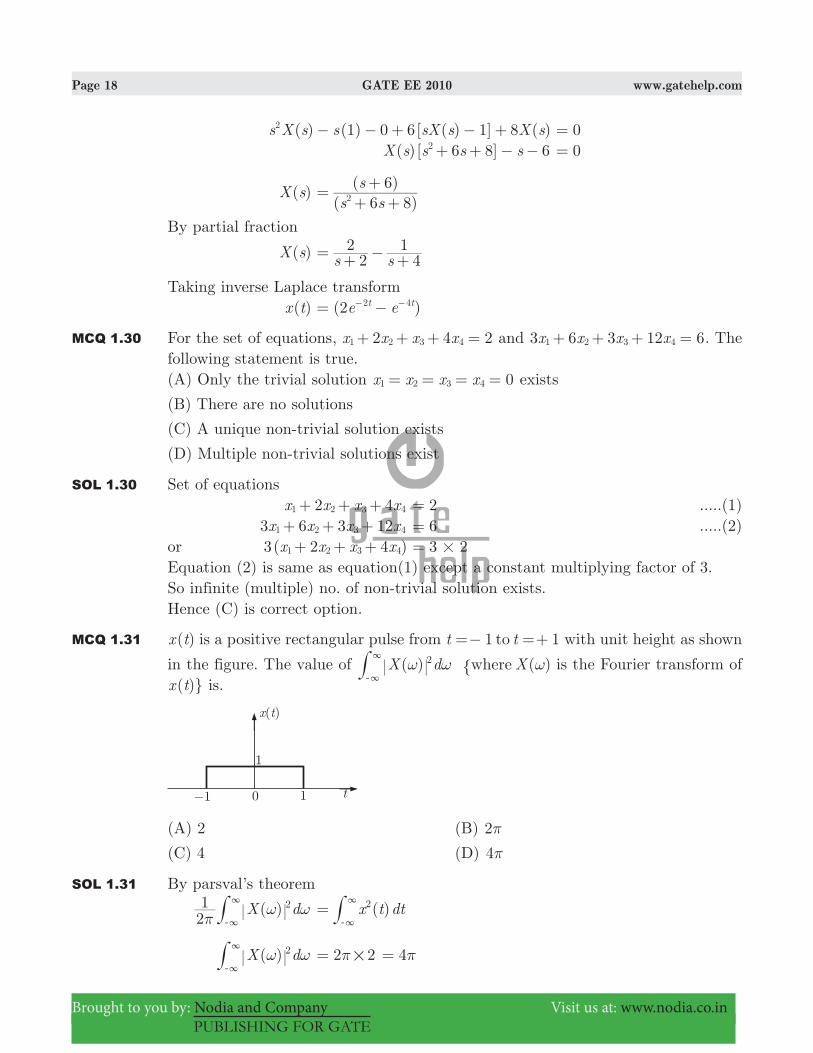
MCQ 1.31 ( )x t is a positive rectangular pulse from 1 1t tto=− =+ with unit height as shown
in the figure. The value of ( ) ( )X d Xwhere2ω ω ω3
3
-"# is the Fourier transform of
( )}x t is.
(A) 2 (B) 2π
(C) 4 (D) 4π
SOL 1.31 By parsval’s theorem
( )X d21 2
πω ω
3
3
-# ( )x t dt2=
3
3
-#
( )X d2ω ω3
3
-# 2 2#π= 4π=

Page 19 GATE EE 2010 www.gatehelp.com
Brought to you by: Nodia and Company Visit us at: www.nodia.co.in
PUBLISHING FOR GATE
Hence option (D) is correct
MCQ 1.32 Given the finite length input [ ]x n and the corresponding finite length output [ ]y n of an LTI system as shown below, the impulse response [ ]h n of the system is
(A) -
[ ] {1, 0, 0, 1}h n = (B) -
[ ] {1, 0, 1}h n =
(C) -
[ ] {1, 1, 1, 1}h n = (D) -
[ ] {1, 1, 1}h n =
SOL 1.32 Given sequences [ ]x n
-
{ , }, n1 1 0 1# #= −
[ ]y n -
{ , , , , }, n1 0 0 0 1 0 4# #= −
If impulse response is [ ]h n then [ ]y n [ ] * [ ]h n x n=Length of convolution ( [ ])y n is 0 to 4, [ ]x n is of length 0 to 1 so length of [ ]h n will be 0 to 3.Let [ ]h n
-
{ , , , }a b c d=
Convolution
[ ]y n -
{ , , , , }a a b b c c d d= − + − + − + −
By comparing a 1= a b− + b a0 1&= = = b c− + c b0 1&= = = c d− + d c0 1&= = =
So, [ ]h n -
{ , , , }1 1 1 1=
Hence option (C) is correct.
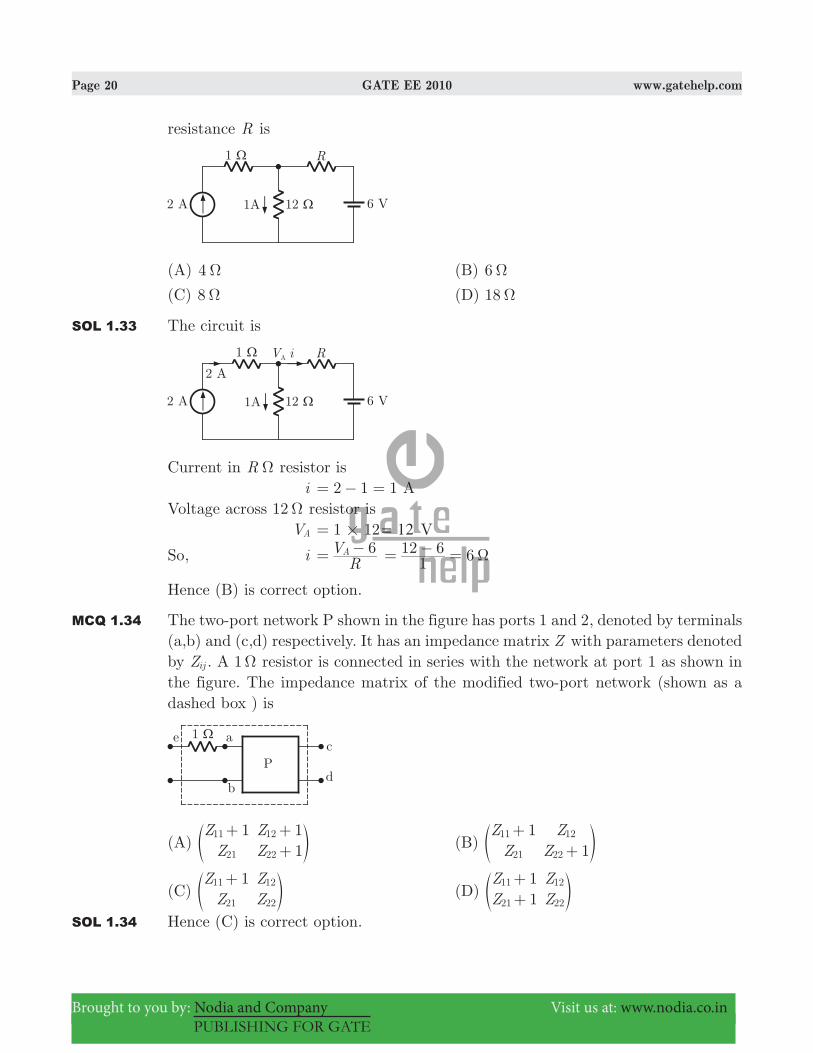
MCQ 1.33 If the 12 Ω resistor draws a current of 1 A as shown in the figure, the value of
Page 20 GATE EE 2010 www.gatehelp.com
Brought to you by: Nodia and Company Visit us at: www.nodia.co.in
PUBLISHING FOR GATE
resistance R is
(A) 4 Ω (B) 6 Ω
(C) 8 Ω (D) 18 Ω
SOL 1.33 The circuit is
Current in R Ω resistor is i 2 1 1= − = AVoltage across 12 Ω resistor is VA 1 12#= 12= V
So, i RV 6A= − 61
12 6 Ω= − =
Hence (B) is correct option.
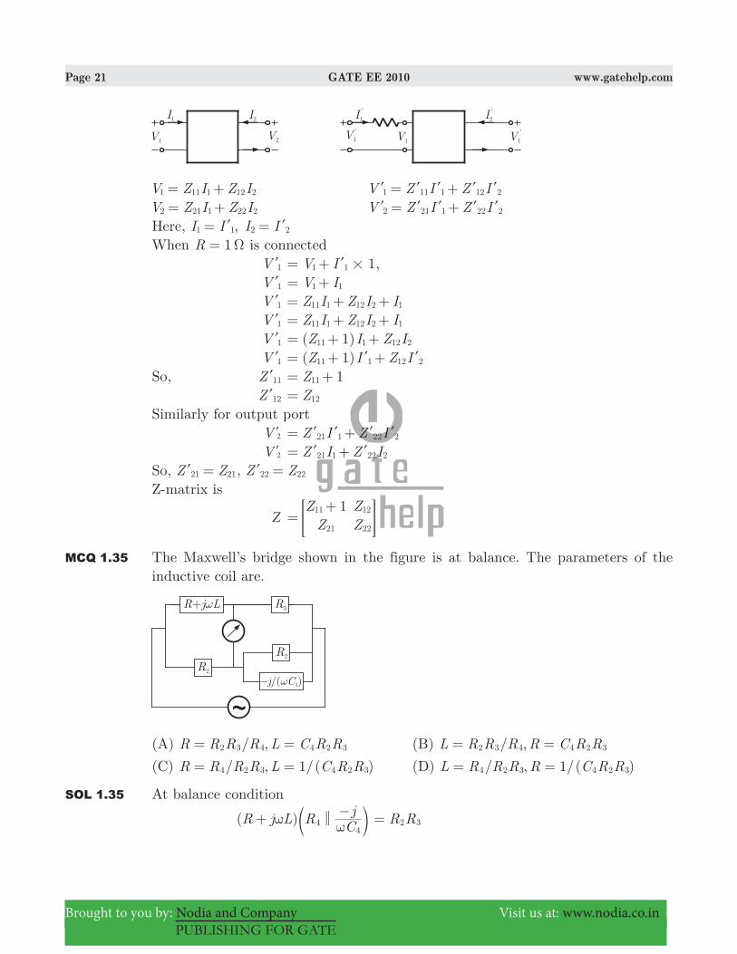
MCQ 1.34 The two-port network P shown in the figure has ports 1 and 2, denoted by terminals (a,b) and (c,d) respectively. It has an impedance matrix Z with parameters denoted by Zij . A 1 Ω resistor is connected in series with the network at port 1 as shown in the figure. The impedance matrix of the modified two-port network (shown as a dashed box ) is
(A) Z
ZZZ
1 11
11
21
12
22
+ ++e o (B)
ZZ
ZZ
11
11
21
12
22
++e o
(C) Z
ZZZ
111
21
12
22
+e o (D)
ZZ
ZZ
11
11
21
12
22
++e o
SOL 1.34 Hence (C) is correct option.
Page 21 GATE EE 2010 www.gatehelp.com
Brought to you by: Nodia and Company Visit us at: www.nodia.co.in
PUBLISHING FOR GATE
V Z I Z I1 11 1 12 2= + V Z I Z I1 11 1 12 2= +l l l l l
V Z I Z I2 21 1 22 2= + V Z I Z I2 21 1 22 2= +l l l l l
Here, ,I I I I1 1 2 2= =l l
When 1R Ω= is connected V 1l 1V I1 1#= + l , V 1l V I1 1= + V 1l Z I Z I I11 1 12 2 1= + + V 1l Z I Z I I11 1 12 2 1= + + V 1l ( 1)Z I Z I11 1 12 2= + + V 1l ( 1)Z I Z I11 1 12 2= + +l l
So, Z 11l 1Z11= + Z 12l Z12=Similarly for output port V 2l Z I Z I21 1 22 2= +l l l l
V 2l Z I Z I21 1 22 2= +l l
So, Z Z21 21=l , Z Z22 22=l
Z-matrix is
Z Z
ZZZ
111
21
12
22=
+> H
MCQ 1.35 The Maxwell’s bridge shown in the figure is at balance. The parameters of the inductive coil are.
(A) / ,R R R R L C R R2 3 4 4 2 3= = (B) / ,L R R R R C R R2 3 4 4 2 3= =
(C) / , 1/( )R R R R L C R R4 2 3 4 2 3= = (D) / , 1/( )L R R R R C R R4 2 3 4 2 3= =
SOL 1.35 At balance condition
( )R j L R Cj
44
<ω ω+ −c m R R2 3=
Page 22 GATE EE 2010 www.gatehelp.com
Brought to you by: Nodia and Company Visit us at: www.nodia.co.in
PUBLISHING FOR GATE
( )R j LR C
jCjR
44
4
4
ω
ω
ω+−
−
c m
R R2 3=
CjRR
CLR
4
4
4
4
ω ωω− + R R R C
jR R2 3 4
4
2 3
ω= −
CjRR
CLR
4
4
4
4
ω− + R R R C
jR R2 3 4
4
2 3
ω= −
By comparing real & imaginary parts.
CRR
4
4
ω CR R
4
2 3
ω=
R RR R
4
2 3=similarly,
CLR
4
4 R R R2 3 4=
L R R C2 3 4=Hence (A) is correct option.
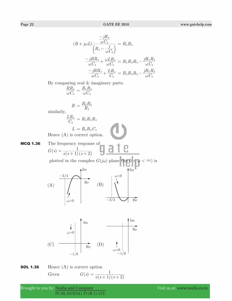
MCQ 1.36 The frequency response of
( )( 1)( 2)
G ss s s
1= + +
plotted in the complex ( )G jω plane 0 )(for < < 3ω is
SOL 1.36 Hence (A) is correct option
Given ( )G s ( )( )s s s1 2
1= + +
Page 23 GATE EE 2010 www.gatehelp.com
Brought to you by: Nodia and Company Visit us at: www.nodia.co.in
PUBLISHING FOR GATE
( )G jω ( )( )j j j1 2
1ω ω ω= + +
( )G jω 1 41
2 2ω ω ω=
+ + ( )G j+ ω ( ) ( / )tan tan90 21 1c ω ω=− − −− −
In nyquist plotFor , ( )G j0ω ω= 3= ( )G j+ ω 90c=− For , ( )G j3ω ω= 0= ( )G j+ ω 90 90 90c c c=− − − 270c=−Intersection at real axis
( )G jω ( )( )j j j1 2
1ω ω ω= + +
( )j j3 2
12ω ω ω
=− + +
( ) ( )
( )j j
j3 2
13 23 2
2 2 2 2
2 2
#ω ω ω ω ω ωω ω ω=
− + − − − −− − −
( )( )j
9 23 2
4 2 2 2
2 2
ω ω ωω ω ω=+ −
− − −
( ) ( )
( )j9 2
39 2
24 2 2 2
2
4 2 2 2
2
ω ω ωω
ω ω ωω ω=
+ −− −
+ −−
At real axis [ ( )]Im G jω 0=
So, ( )
( )9 2
24 2 2
2
ω ω ωω ω+ −
− 0=
2 02 &ω− = 2ω = rad/secAt 2ω = rad/sec, magnitude response is
( )G jat 2
ωω =
2 2 1 2 4
1=+ +
61
43<=
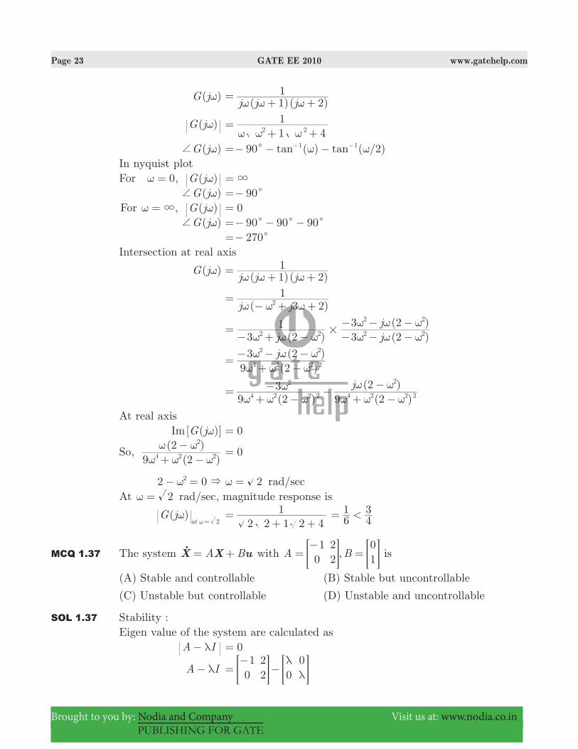
MCQ 1.37 The system A BuX X= +o with ,A B1
022
01=
−=> >H H is
(A) Stable and controllable (B) Stable but uncontrollable
(C) Unstable but controllable (D) Unstable and uncontrollable
SOL 1.37 Stability :Eigen value of the system are calculated as A Iλ− 0=
A Iλ− 1
022 0
0λλ=
−−> >H H
Page 24 GATE EE 2010 www.gatehelp.com
Brought to you by: Nodia and Company Visit us at: www.nodia.co.in
PUBLISHING FOR GATE
10
22
λλ=
− −−> H
A Iλ− ( 1 )(2 ) 2 00#λ λ= − − − − =& ,1 2λ λ ,1 2=−Since eigen values of the system are of opposite signs, so it is unstableControllability :
A 1
022=
−> H, B
01= > H
AB 22= > H
[ : ]B AB 01
22= > H
:B AB6 @ 0=YSo it is controllable.Hence (C) is correct option.
MCQ 1.38 The characteristic equation of a closed-loop system is ( 1)( 3) ( 2)s s s k s+ + + 0, 0k >= .Which of the following statements is true ?
(A) Its root are always real
(B) It cannot have a breakaway point in the range [ ]Re s1 0< <−
(C) Two of its roots tend to infinity along the asymptotes [ ]Re s 1=−
(D) It may have complex roots in the right half plane.
SOL 1.38 Given characteristic equation ( 1)( 3) ( 2)s s s K s+ + + + 0= ; K 0> ( 4 3)s s s K(s 2)2 + + + + 0= 4 (3 ) 2s s K s K3 2+ + + + 0=From Routh’s tabulation method
s3 1 K3 +
s2 4 K2
s1 ( )0
K K K4
4 3 24
12 2(1) >+ − = +
s0 K2
There is no sign change in the first column of routh table, so no root is lying in right half of s -plane.For plotting root locus, the equation can be written as
( )( )
( )s s s
K s1
1 32+ + +
+ 0=
Page 25 GATE EE 2010 www.gatehelp.com
Brought to you by: Nodia and Company Visit us at: www.nodia.co.in
PUBLISHING FOR GATE
Open loop transfer function ( )G s ( )( )
( )s s s
K s1 3
2= + ++
Root locus is obtained in following steps:• No. of poles n 3= , at 0, 1s s= =− and 3s =−• No. of Zeroes m 1= , at s 2=−• The root locus on real axis lies between s 0= and s 1=− , between s 3=− and
s 2=− .• Breakaway point lies between open loop poles of the system. Here breakaway
point lies in the range [ ]Re s1 0< <− .• Asymptotes meet on real axis at a point C , given by
C n mreal part of poles real parts of zeroes= −
− //
( ) ( )
3 10 1 3 2= −
− − − −
1=−As no. of poles is 3, so two root loci branches terminates at infinity along asymptotes
( )Re s 1=−Hence (C) is correct option.
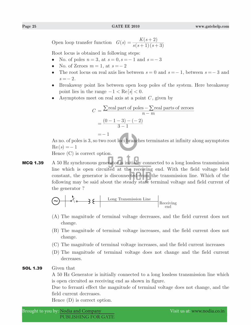
MCQ 1.39 A 50 Hz synchronous generator is initially connected to a long lossless transmission line which is open circuited at the receiving end. With the field voltage held constant, the generator is disconnected from the transmission line. Which of the following may be said about the steady state terminal voltage and field current of the generator ?
(A) The magnitude of terminal voltage decreases, and the field current does not change.
(B) The magnitude of terminal voltage increases, and the field current does not change.
(C) The magnitude of terminal voltage increases, and the field current increases
(D) The magnitude of terminal voltage does not change and the field current decreases.
SOL 1.39 Given thatA 50 Hz Generator is initially connected to a long lossless transmission line which is open circuited as receiving end as shown in figure.Due to ferranti effect the magnitude of terminal voltage does not change, and the field current decreases.Hence (D) is correct option.
Page 26 GATE EE 2010 www.gatehelp.com
Brought to you by: Nodia and Company Visit us at: www.nodia.co.in
PUBLISHING FOR GATE
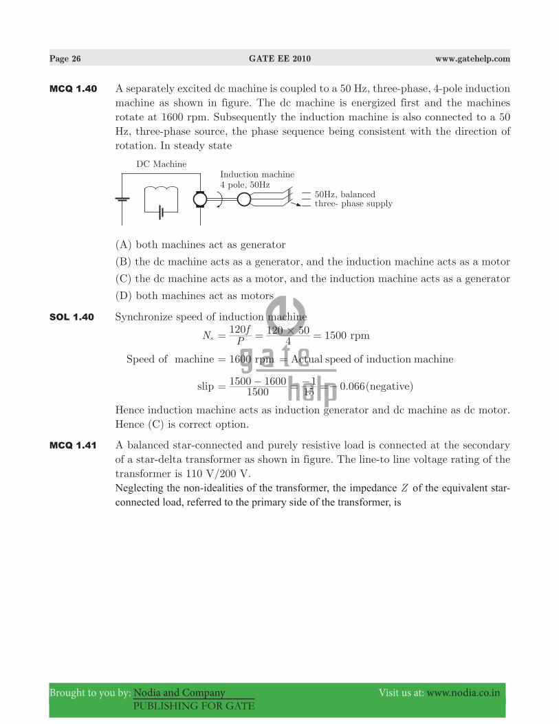
MCQ 1.40 A separately excited dc machine is coupled to a 50 Hz, three-phase, 4-pole induction machine as shown in figure. The dc machine is energized first and the machines rotate at 1600 rpm. Subsequently the induction machine is also connected to a 50 Hz, three-phase source, the phase sequence being consistent with the direction of rotation. In steady state
(A) both machines act as generator
(B) the dc machine acts as a generator, and the induction machine acts as a motor
(C) the dc machine acts as a motor, and the induction machine acts as a generator
(D) both machines act as motors
SOL 1.40 Synchronize speed of induction machine
Ns 1500Pf120
4120 50 rpm#= = =
Speed of machine 1600 rpm= Actual speed of induction machine=
slip .06615001500 1600
151 0= − = − =− (negative)
Hence induction machine acts as induction generator and dc machine as dc motor.Hence (C) is correct option.
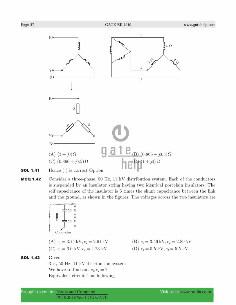
MCQ 1.41 A balanced star-connected and purely resistive load is connected at the secondary of a star-delta transformer as shown in figure. The line-to line voltage rating of the transformer is 110 V/200 V.Neglecting the non-idealities of the transformer, the impedance Z of the equivalent star-connected load, referred to the primary side of the transformer, is
Page 27 GATE EE 2010 www.gatehelp.com
Brought to you by: Nodia and Company Visit us at: www.nodia.co.in
PUBLISHING FOR GATE
(A) ( )j3 0 Ω+ (B) ( . . )j0 866 0 5 Ω−
(C) ( . . )j0 866 0 5 Ω+ (D) (1 0)j Ω+
SOL 1.41 Hence ( ) is correct Option
MCQ 1.42 Consider a three-phase, 50 Hz, 11 kV distribution system. Each of the conductors is suspended by an insulator string having two identical porcelain insulators. The self capacitance of the insulator is 5 times the shunt capacitance between the link and the ground, as shown in the figures. The voltages across the two insulators are
(A) 3.74 , 2.61e ekV kV21 = = (B) 3.46 , 2.89e ekV kV1 2= =
(C) 6.0 , 4.23e ekV kV1 2= = (D) 5.5 , 5.5e ekV kV1 2= =
SOL 1.42 Given3-φ, 50 Hz, 11 kV distribution systemWe have to find out , ?e e1 2 =Equivalent circuit is as following
Page 28 GATE EE 2010 www.gatehelp.com
Brought to you by: Nodia and Company Visit us at: www.nodia.co.in
PUBLISHING FOR GATE
e1 ( )
3.46C C
C
6 53
11 6
311
116
#= + = = kV
e2 3
11115
#=
2.89= kVHence (B) is correct option.
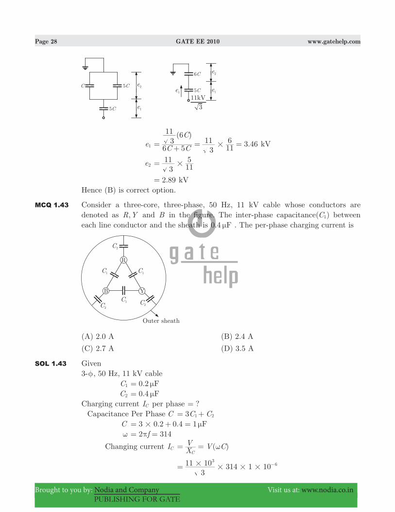
MCQ 1.43 Consider a three-core, three-phase, 50 Hz, 11 kV cable whose conductors are denoted as ,R Y and B in the figure. The inter-phase capacitance(C1) between each line conductor and the sheath is 0.4 Fμ . The per-phase charging current is
(A) 2.0 A (B) 2.4 A
(C) 2.7 A (D) 3.5 A
SOL 1.43 Given3-φ, 50 Hz, 11 kV cable C1 0.2 Fμ= C2 0.4 Fμ=Charging current IC per phase ?= Capacitance Per Phase C C C3 1 2= + C 3 0.2 0.4 1 F# μ= + = ω 2 314fπ= =
Changing current IC ( )XV V C
Cω= =
3
11 10 314 1 103
6## # #= −
Page 29 GATE EE 2010 www.gatehelp.com
Brought to you by: Nodia and Company Visit us at: www.nodia.co.in
PUBLISHING FOR GATE
2= AmpHence (A) is correct option
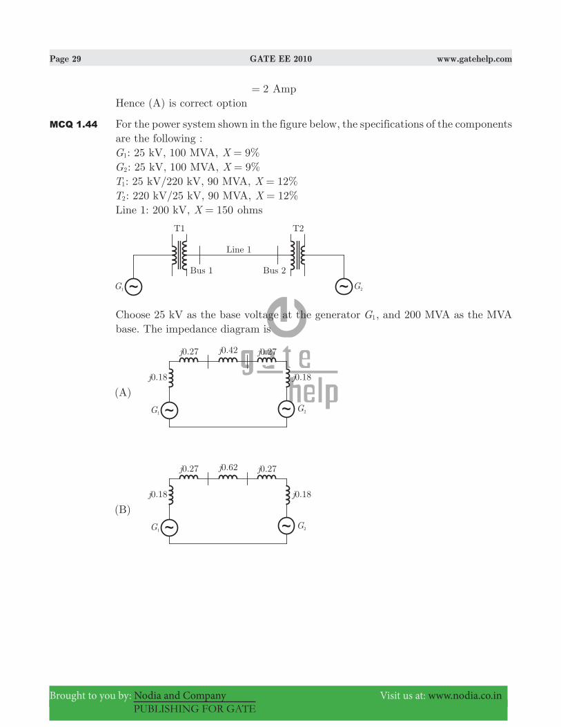
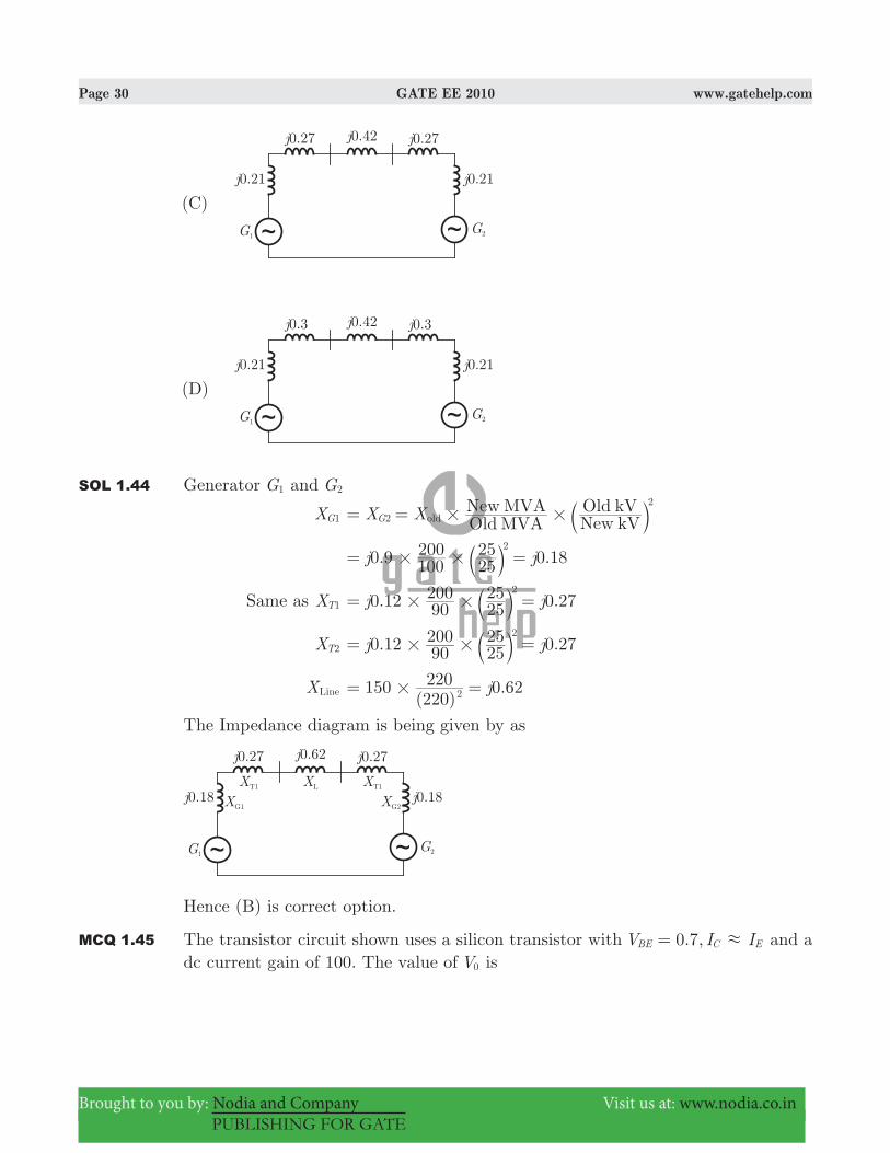
MCQ 1.44 For the power system shown in the figure below, the specifications of the components are the following :G1: 25 kV, 100 MVA, %X 9=G2: 25 kV, 100 MVA, %X 9=T1: 25 kV/220 kV, 90 MVA, %X 12=T2: 220 kV/25 kV, 90 MVA, %X 12=Line 1: 200 kV, X 150= ohms
Choose 25 kV as the base voltage at the generator G1, and 200 MVA as the MVA base. The impedance diagram is
Page 30 GATE EE 2010 www.gatehelp.com
Brought to you by: Nodia and Company Visit us at: www.nodia.co.in
PUBLISHING FOR GATE
SOL 1.44 Generator G1 and G2
XG1 X X Old MVANew MVA
New kVOld kV
G2
2
old # #= = b l
0.9 0.18j j100200
2525 2
# #= =b l
Same as XT1 0.12 0.27j j90200
2525 2
# #= =b l
XT2 . .j j0 12 90200
2525 0 27
2
# #= =b l
XLine ( ).j150
220220 0 622#= =
The Impedance diagram is being given by as
Hence (B) is correct option.
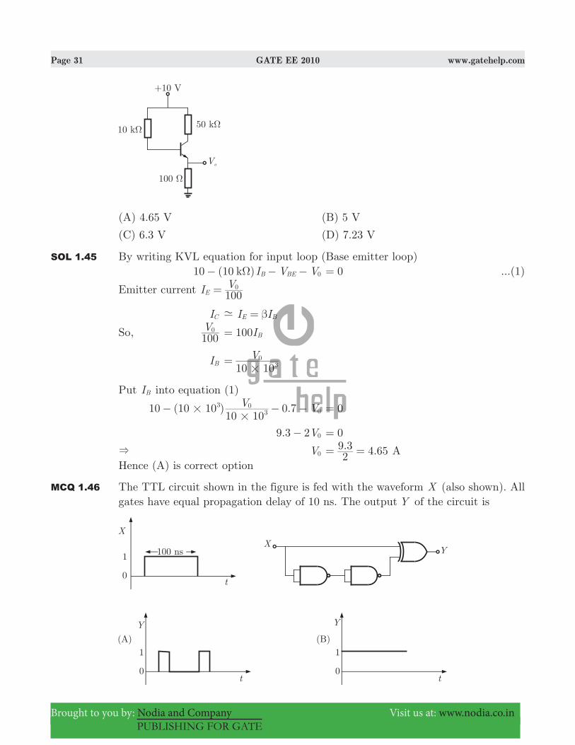
MCQ 1.45 The transistor circuit shown uses a silicon transistor with . ,V I I0 7BE C E.= and a dc current gain of 100. The value of V0 is
Page 31 GATE EE 2010 www.gatehelp.com
Brought to you by: Nodia and Company Visit us at: www.nodia.co.in
PUBLISHING FOR GATE
(A) 4.65 V (B) 5 V
(C) 6.3 V (D) 7.23 V
SOL 1.45 By writing KVL equation for input loop (Base emitter loop) 10 (10 )I V Vk B BE 0Ω− − − 0= ...(1)
Emitter current I V100E
0=
IC I IE B- β=
So, V100
0 100IB=
IB V10 103
0
#=
Put IB into equation (1)
10 (10 10 ) 0.7V V10 10
33
00#
#− − − 0=
. V9 3 2 0− 0=
& V0 . .2
9 3 4 65= = AHence (A) is correct option
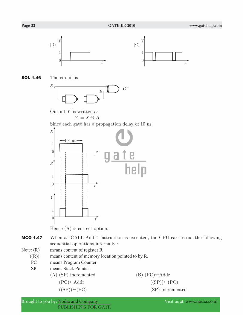
MCQ 1.46 The TTL circuit shown in the figure is fed with the waveform X (also shown). All gates have equal propagation delay of 10 ns. The output Y of the circuit is
Page 32 GATE EE 2010 www.gatehelp.com
Brought to you by: Nodia and Company Visit us at: www.nodia.co.in
PUBLISHING FOR GATE
SOL 1.46 The circuit is
Output Y is written as Y X B5=Since each gate has a propagation delay of 10 ns.
Hence (A) is correct option.
MCQ 1.47 When a “CALL Addr” instruction is executed, the CPU carries out the following sequential operations internally :
Note: (R) means content of register R ((R)) means content of memory location pointed to by R. PC means Program Counter SP means Stack Pointer
(A) (SP) incremented (B) (PC)!Addr
(PC)!Addr ((SP))!(PC)
((SP))!(PC) (SP) incremented

Page 33 GATE EE 2010 www.gatehelp.com
Brought to you by: Nodia and Company Visit us at: www.nodia.co.in
PUBLISHING FOR GATE
(C) (PC)!Addr (D) ((SP))!(PC)
(SP) incremented (SP) incremented
((SP))!(PC) (PC)!Addr
SOL 1.47 CALL, Address performs two operations (1) PUSH PC &Save the contents of PC (Program Counter) into stack.
SP 2SP= − (decrement) (( ))SP ( )PC!
(2) Addr stored in PC. ( )PC Addr!
Hence (D) is correct option.
Common Data Questions : 48 and 49A separately excited DC motor runs at 1500 rpm under no-load with 200 V applied to the armature. The field voltage is maintained at its rated value. The speed of the motor, when it delivers a torque of5 Nm, is 1400 rpm as shown in figure. The rotational losses and armature reaction are neglected.
MCQ 1.48 The armature resistance of the motor is(A) 2 Ω (B) 3.4 Ω
(C) 4.4 Ω (D) 7.7 Ω
SOL 1.48 Hence (B) is correct option. Given no-load speed N1 1500= rpm Va 200 T NV, 5 Nm, 1400 rpm= = =emf at no load Eb1 200V Va= =
N Eb\ NN
EE
b
b
2
1
2
1& =
Eb2 200 186.67NN E 1500
1400 V1
2b1 #= = =b l

Page 34 GATE EE 2010 www.gatehelp.com
Brought to you by: Nodia and Company Visit us at: www.nodia.co.in
PUBLISHING FOR GATE
a T / . 5E I I2 1400186 67 60
b a a&#
#ω π= =^ h
Ia 3.926 A=
a V E I Rb a a= +
Ra .. 3.4I
V E3 926
200 186 67a
a b Ω= − = − =
MCQ 1.49 For the motor to deliver a torque of 2.5 Nm at 1400 rpm, the armature voltage to be applied is(A) 125.5 V (B) 193.3 V
(C) 200 V (D) 241.7 V
SOL 1.49 Hence (B) is correct option. T 2.5 Nm= at 1400 rpmthan V ?=
a T E Ib b
~=
.2 5 . I2 1400
186 6 60a
## #
π=
Ia 1.963 A= V E I Rb a a= + . . .186 6 1 963 3 4#= + 193.34 V=
Common Data Questions: 50 and 51Given ( )f t and ( )g t as show below
MCQ 1.50 ( )g t can be expressed as
(A) ( ) ( )g t f t2 3= − (B) ( )g t f t2
3= −` j
(C) ( )g t f t223= −` j (D) ( )g t f t
2 23= −` j
SOL 1.50 We can observe that if we scale ( )f t by a factor of 21 and then shift, we will get
( )g t .
First scale ( )f t by a factor of 21
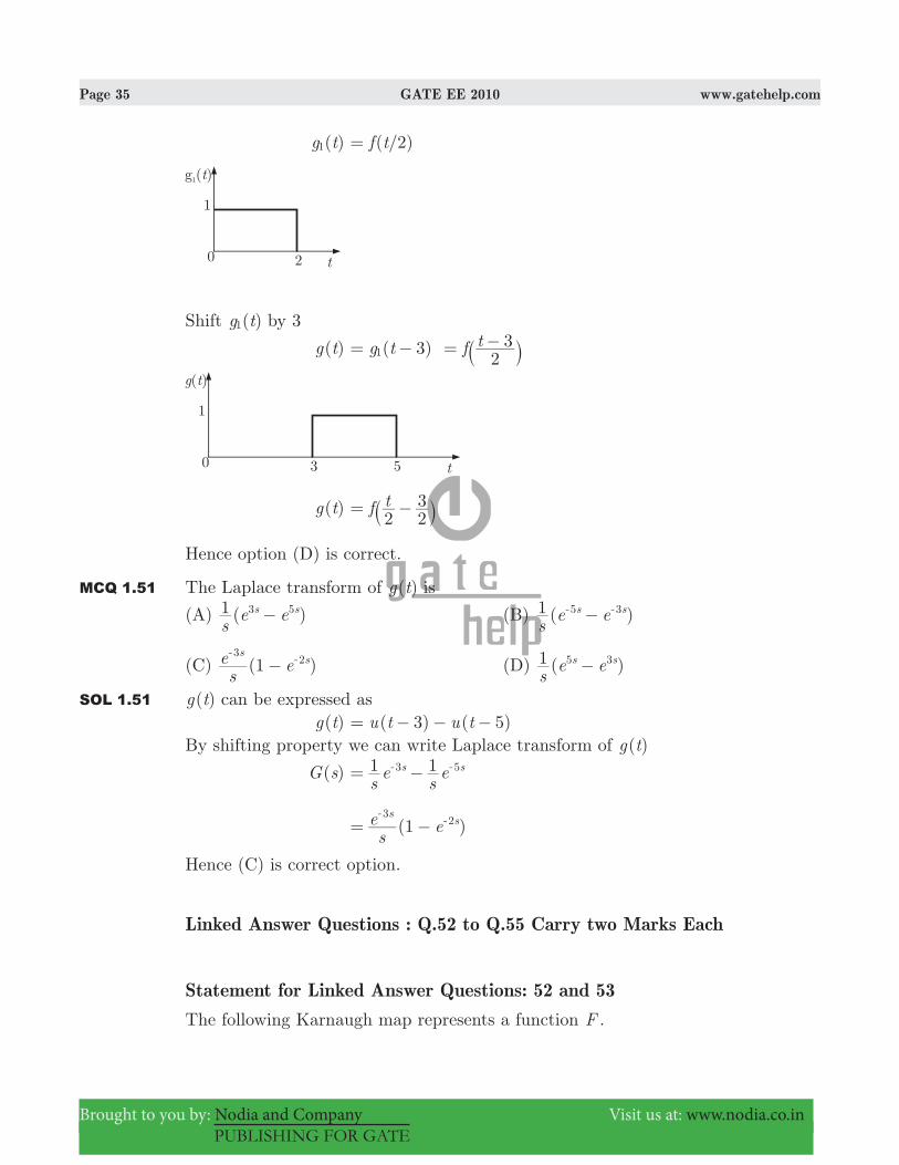
Page 35 GATE EE 2010 www.gatehelp.com
Brought to you by: Nodia and Company Visit us at: www.nodia.co.in
PUBLISHING FOR GATE
( )g t1 ( /2)f t=
Shift ( )g t1 by 3
( )g t ( )g t f t32
31= − = −
` j
( )g t f t2 2
3= −` j
Hence option (D) is correct.
MCQ 1.51 The Laplace transform of ( )g t is
(A) ( )s
e e1 s s3 5− (B) ( )s
e e1 s s5 3−- -
(C) (1 )s
e es
s3
2−-
- (D) ( )s
e e1 s s5 3−
SOL 1.51 ( )g t can be expressed as ( )g t ( 3) ( 5)u t u t= − − −By shifting property we can write Laplace transform of ( )g t
( )G s s
es
e1 1s s3 5= −- -
(1 )s
e es
s3
2= −-
-
Hence (C) is correct option.
Linked Answer Questions : Q.52 to Q.55 Carry two Marks Each
Statement for Linked Answer Questions: 52 and 53The following Karnaugh map represents a function F .

Page 36 GATE EE 2010 www.gatehelp.com
Brought to you by: Nodia and Company Visit us at: www.nodia.co.in
PUBLISHING FOR GATE
MCQ 1.52 A minimized form of the function F is(A) F X Y YZ= + (B) F X Y YZ= +
(C) F X Y Y Z= + (D) F X Y Y Z= +
SOL 1.52 Function F can be minimized by grouping of all 1’s in K-map as following.
F X Y YZ= +Hence (B) is correct option.
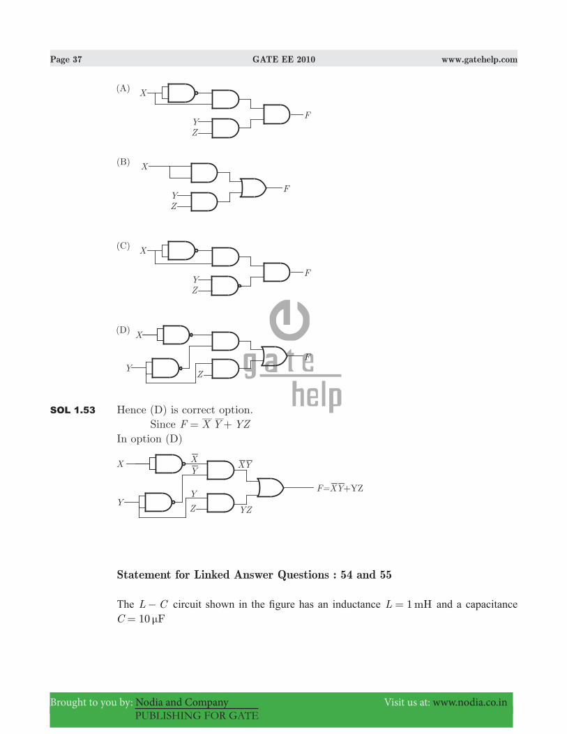
MCQ 1.53 Which of the following circuits is a realization of the above function F ?
Page 37 GATE EE 2010 www.gatehelp.com
Brought to you by: Nodia and Company Visit us at: www.nodia.co.in
PUBLISHING FOR GATE
SOL 1.53 Hence (D) is correct option. Since F X Y YZ= +In option (D)
Statement for Linked Answer Questions : 54 and 55
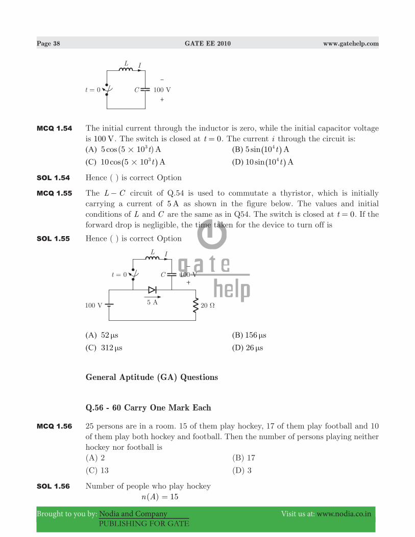
The L C− circuit shown in the fi gure has an inductance 1 mHL = and a capacitance 10 FC μ=
Page 38 GATE EE 2010 www.gatehelp.com
Brought to you by: Nodia and Company Visit us at: www.nodia.co.in
PUBLISHING FOR GATE
MCQ 1.54 The initial current through the inductor is zero, while the initial capacitor voltage is 100 V. The switch is closed at t 0= . The current i through the circuit is:(A) 5 (5 10 )cos At3
# (B) 5 sin At104^ h
(C) 10cos At5 103#^ h (D) 10 sin At104
^ h
SOL 1.54 Hence ( ) is correct Option
MCQ 1.55 The L C− circuit of Q.54 is used to commutate a thyristor, which is initially carrying a current of 5 A as shown in the figure below. The values and initial conditions of L and C are the same as in Q54. The switch is closed at t 0= . If the forward drop is negligible, the time taken for the device to turn off is
SOL 1.55 Hence ( ) is correct Option
(A) 52 sμ (B) 156 sμ
(C) 312 sμ (D) 26 sμ
General Aptitude (GA) Questions
Q.56 - 60 Carry One Mark Each
MCQ 1.56 25 persons are in a room. 15 of them play hockey, 17 of them play football and 10 of them play both hockey and football. Then the number of persons playing neither hockey nor football is(A) 2 (B) 17
(C) 13 (D) 3
SOL 1.56 Number of people who play hockey ( )n A 15=

Page 39 GATE EE 2010 www.gatehelp.com
Brought to you by: Nodia and Company Visit us at: www.nodia.co.in
PUBLISHING FOR GATE
Number of people who play football ( )n B 17=Persons who play both hockey and football ( )n A B+ 10=Persons who play either hockey or football or both : ( )n A B, ( ) ( ) ( )n A n B n A B+= + − 15 17 10 22= + − =Thus people who play neither hockey nor football 25 22 3= − =Hence (D) is correct option.
MCQ 1.57 The question below consists of a pair of related words followed by four pairs of words. Select the pair that best expresses the relation in the original pair.Unemployed : Worker(A) fallow: land (B) unaware: sleeper
(C) wit: jester (D) renovated: house
SOL 1.57 A worker may by unemployed. Like in same relation a sleeper may be unaware.Hence (B) is correct option.
MCQ 1.58 Choose the most appropriate word from the options given below to complete the following sentence If we manage to ____________ our natural resources, we would leave a better planet for our children.(A) uphold (B) restrain
(C) cherish (D) conserve
SOL 1.58 Here conserve is most appropriate word.Hence (D) is correct option.
MCQ 1.59 Which of the following options is closest in meaning to the word: Circuitous?(A) cyclic (B) indirect
(C) confusing (D) crooked
SOL 1.59 Circuitous means round about or not direct. Indirect is closest in meaning to this circuitous(A) Cyclic : Recurring in nature(B) Indirect : Not direct(C) Confusing : lacking clarity of meaning(D) Crooked : set at an angle; not straightHence (B) is correct option.
MCQ 1.60 Choose the most appropriate word from the options given below to the complete the following sentence:His rather casual remarks on politics ___________ his lack of seriousness about the subject.

Page 40 GATE EE 2010 www.gatehelp.com
Brought to you by: Nodia and Company Visit us at: www.nodia.co.in
PUBLISHING FOR GATE
(A) masked (B) belied
(C) betrayed (D) suppressed
SOL 1.60 Betrayed means reveal unintentionally that is most appropriate.Hence (C) is correct option.
Q. 61 - 65 Carry Two Marks Each
MCQ 1.61 Hari (H), Gita (G), Irfan (I) and Saira (S) are siblings (i.e. brothers and sisters). All were born on 1st January. The age difference between any two successive siblings (that is born one after another) is less than 3 years. Given the following facts:i. Hari’s age + Gita’s age > Irfan’s age + Saira’s age
ii. The age difference between Gita and Saira is 1 year. However Gita is not the oldest and Saira is not the youngest.
iii. There are no twins.
In what order were they born (oldest first)?(A) HSIG (B) SGHI
(C) IGSH (D) IHSG
SOL 1.61 Let H , G , S and I be ages of Hari, Gita, Saira and Irfan respectively.Now from statement (1) we have H G > I S+ +Form statement (2) we get that G S 1− = or S G 1− = As G can’t be oldest and S can’t be youngest thus either GS or SG possible.From statement (3) we get that there are no twins (A) HSIG : There is I between S and G which is not possible
(B) SGHI : SG order is also here and S > G > H > I G H > S Iand + + which is possible.
(C) IGSH : This gives I G> and S H> and adding these both inequalities we have I S H G>+ + which is not possible.
(D) IHSG : This gives I H> and S G> and adding these both inequalities we have I S H G>+ + which is not possible.
Hence (B) is correct option.
MCQ 1.62 5 skilled workers can build a wall in 20days; 8 semi-skilled workers can build a wall in 25 days; 10 unskilled workers can build a wall in 30days. If a team has 2 skilled, 6 semi-skilled and 5 unskilled workers, how long will it take to build the wall?(A) 20 (B) 18
(C) 16 (D) 15
SOL 1.62 Let W be the total work.
Per day work of 5 skilled workers W20=

Page 41 GATE EE 2010 www.gatehelp.com
Brought to you by: Nodia and Company Visit us at: www.nodia.co.in
PUBLISHING FOR GATE
Per day work of one skill worker W W5 20 100#
= =
Similarly per day work of 1 semi-skilled workers W W8 25 200#
= =
Similarly per day work of one semi-skill worker W W10 30 300#
= =
Thus total per day work of 2 skilled, 6 semi-skilled and 5 unskilled workers is 2 6 5 12 18 10W W W W W W W100 200 300 600 15= + + = + + =
Therefore time to complete the work is 15 days.Hence (D) is correct option.
MCQ 1.63 Modern warfare has changed from large scale clashes of armies to suppression of civilian populations. Chemical agents that do their work silently appear to be suited to such warfare; and regretfully, there exist people in military establishments who think that chemical agents are useful tools for their cause.Which of the following statements best sums up the meaning of the above passage:(A) Modern warfare has resulted in civil strife.
(B) Chemical agents are useful in modern warfare.
(C) Use of chemical agents in warfare would be undesirable
(D) People in military establishments like to use chemical agents in war.
SOL 1.63 Hence (D) is correct option.
MCQ 1.64 Given digits 2,2,3,3,4,4,4,4 how many distinct 4 digit numbers greater than 3000 can be formed?(A) 50 (B) 51
(C) 52 (D) 54
SOL 1.64 As the number must be greater than 3000, it must be start with 3 or 4. Thus we have two case:Case (1) If left most digit is 3 an other three digits are any of 2, 2, 3, 3, 4, 4, 4, 4.
(1) Using 2, 2, 3 we have 3223, 3232, 3322 i.e. !! 32
3 = no.
(2) Using 2,2,4 we have 3224, 3242, 3422 i.e. !! 32
3 = no.
(3) Using 2,3,3 we have 233, 323, 3323 3 3 i.e. !! 32
3 = no.
(4) Using 2,3,4 we have !3 6= no.
(5) Using 2,4,4 we have 244, 424, 4423 3 3 i.e. !! 32
3 = no.
(6) Using 3,3,4 we have 334, 343, 4333 3 3 i.e. !! 32
3 = no.

Page 42 GATE EE 2010 www.gatehelp.com
Brought to you by: Nodia and Company Visit us at: www.nodia.co.in
PUBLISHING FOR GATE
(7) Using 3,4,4 we have 344, 434, 4433 3 3 i.e. !! 32
3 = no.
(8) Using 4,4,4 we have 3444 i.e. !!
33 1= no.
Total 4 digit numbers in this case is1 3 3 3 6 3 3 3 1 25+ + + + + + + + =Case 2 : If left most is 4 and other three digits are any of 2, 2, 3, 3, 3, 4, 4, 4.
(1) Using 2,2,3 we have 4223, 4232, 4322 i.e. . !! 32
3 = no
(2) Using 2,2,4 we have 4224, 4242, 4422 i.e. . !! 32
3 = no
(3) Using 2,3,3 we have 4233, 4323, 4332 i.e. . !! 32
3 = no
(4) Using 2,3,4 we have i.e. . !3 6= no
(5) Using 2,4,4 we have 4244, 4424, 4442 i.e. . !! 32
3 = no
(6) Using 3,3,3 we have 4333 i.e !!
33 1= . no.
(7) Using 3,3,4 we have 4334, 4343, 4433 i.e. . !! 32
3 = no
(8) Using 3,4,4 we have 4344, 4434, 4443 i.e. . !! 32
3 = no
(9) Using 4,4,4 we have 4444 i.e. !!
33 1= . no
Total 4 digit numbers in 2nd case 3 3 3 6 3 3 1 3 1 26= + + + + + + + + =Thus total 4 digit numbers using case (1) and case (2) is 25 26 51= + =Hence (B) is correct option
MCQ 1.65 If 137+276=435 how much is 731+672?(A) 534 (B) 1403
(C) 1623 (D) 1513
SOL 1.65 Since 7 6 13+ = but unit digit is 5 so base may be 8 as 5 is the remainder when 13 is divided by 8. Let us check.
137
276435
8
8 731
6721623
8
8 Thus here base is 8. Now
Hence (C) is correct option.

Page 43 GATE EE 2010 www.gatehelp.com
Brought to you by: Nodia and Company Visit us at: www.nodia.co.in
PUBLISHING FOR GATE
Answer Sheet
1. (B) 13. (C) 25. (A) 37. (C) 49. (B) 61. (B)2. (A) 14. (C) 26. (D) 38. (C) 50. (D) 62. (D)3. (D) 15. (*) 27. (C) 39. (D) 51. (C) 63. (D)4. (B) 16. (A) 28. (B) 40. (C) 52. (B) 64. (B)5. (B) 17. (A) 29. (B) 41. (*) 53. (D) 65. (C)6. (*) 18. (C) 30. (C) 42. (B) 54. (*)7. (B) 19. (C) 31. (D) 43. (A) 55. (*)8. (D) 20. (B) 32. (C) 44. (B) 56. (D)9. (D) 21. (A) 33. (B) 45. (A) 57. (B)10. (A) 22. (B) 34. (C) 46. (A) 58. (D)11. (C) 23. (A) 35. (A) 47. (D) 59. (B)12. (*) 24. (C) 36. (A) 48. (B) 60. (C)
**********