Embed Size (px)
Citation preview
EE 304 Communication Theory
Final Project Report
Title: Cooperative Relaying using USRP and GNU Radio
Authors:
Lokesh Bairwa (B15220)
Shrawan Kumar(B15235)
Submission Date: June 1, 2017
Course Instructor : Dr. Siddhartha Sarma
IIT Mandi(HP)
Contents
1 Introduction 4
2 Problem statement 5
3 Deliverables 5
4 Equipments required for this project 5
5 Block diagram of the experimental setup 6
6 Theory 6
7 Division of work 7
8 Timeline 7
9 Interfacing With USRPs 8
10 Lessons Learned 15
11 Conclusion and Future scope 15
12 Appendices 16
2
List of Figures
1 Block Diagram For Experimental Setup . . . . . . . . . . . . . . . . . . . . . . . . . 6
2 Gauntt Chart for Timeline . . . . . . . . . . . . . . . . . . . . . . . . . . . . . . . . . 8
3 Setting USRP with GNURadio . . . . . . . . . . . . . . . . . . . . . . . . . . . . . . 8
4 GRC Flow graph for Transmitter . . . . . . . . . . . . . . . . . . . . . . . . . . . . . 9
5 GRC Flow graph for FFT sink when Transmit message signal . . . . . . . . . . . . . 9
6 GRC Flow graph of Receiver for Direct Communication . . . . . . . . . . . . . . . . 10
7 GRC Flow graph of Relay as Amplify And Forward . . . . . . . . . . . . . . . . . . 11
8 Waveform when Realy used as Amplify and Forward . . . . . . . . . . . . . . . . . . 12
9 GRC Flow graph of Relay as Decode And Forward . . . . . . . . . . . . . . . . . . . 12
10 FFT Sink when Relay used as Decode And Forward . . . . . . . . . . . . . . . . . . 13
11 GRC Flow graph for Final Receiver . . . . . . . . . . . . . . . . . . . . . . . . . . . 14
12 GRC Flow graph of Relay as Decode And Forward . . . . . . . . . . . . . . . . . . . 14
13 NI USRP 2920 . . . . . . . . . . . . . . . . . . . . . . . . . . . . . . . . . . . . . . . 16
3
Abstract
This article will encourage the readers to apply new ideas for cooperative communica-
tion.From last few decades the largest development occurs in wireless communication.Every
day new technology or approach is developing. With the help of current technology (Smart-
phone,Webcam,Radio etc) or hardware based devices we can contact with anyone from one cor-
ner of world to the other corner.Now a days user wants better quality of received signal with
maximum rate so as to full fill these requirement researches going on.The cooperative communi-
cation using Relay or Mediator is also such type of technique that is growing at very fast rate.In
traditional networks, direct communication is done between two nodes. In cooperative commu-
nication, communication is done by using relay between source and destination. It improves
the system efficiency and performance significantly. It is one of the fastest growing technology
and reliable network. We have implemented this technique using GNU Radio software it is open
source software ,and three USRPs( Universal Software Radio Peripheral) acting as transmitter,
relay and receiver. In this type of communication receiver can be a more number of users with
one transmitter. We have also verified the direct communication between source and destina-
tion.In cooperative communication between transmitter and receiver we used relay as amplify
and forward as well as decode and forward. In this article an overview on cooperative communi-
cation has been presented. We have used GMSK(Gaussian Minimum Shift keying) modulation
and demodulation technique.
1 Introduction
In todays world users of wireless devices expect high data rates without any possible distortion
in transmitted signal. This expectation is not an easy thing to implement because the radio fre-
quency signal propagating through environment get distorted due to diffraction ,interference and
transmission through materials.The signals received by receiver is from the multipath the phases
and amplitude is different and when combination and alignment is occurs the same phase signals
produce strong signal and different phases produce weak signals and there is more chance to get dif-
ferent phases.SO to avoid this problem scientists developed MIMO technique that is multiple input
multiple output in this the signal is transmitted on independent path that is distributed in frequency
time and space and combine at receiver end. But this approach is also less feasible due to less size
of antenna of mobile devices.SO a new technique is originated in which without the use of multiple
4
antennas we use relay in between the transmitter and Receiver as a mediator to enhance the signal
quality.
2 Problem statement
Our main objective in this project is to hands on experiment the Cooperative Communication Using
USRP and GNU Radio which is most commonly used software based platform.
1. Direct Link Transmission
2. Then introduce a relay in between transmitter and receiver using GMSK modulation technique.
3 Deliverables
Here are the list of things which has to be demonstrated after this project done
• How file transfer taken place using a Relay inserted in between Tx and Rx
• Why decode and forward method is better then amplify and forward as implementation of relay
• GMSK Modulation and Demodulation
4 Equipments required for this project
To implement Cooperative Communication using relay we require the following equipments.
1. NI USRP-2920 (Qty:03)
2. Ac/DC Power Supply Adapter for USRP
3. PC with GNU Radio Installed
4. Gigabit Ethernet Cable
5. Vert 400 Antenna(Qty:04)
5

5 Block diagram of the experimental setup
Here is the block diagram for experimental setup in this each block will represented by one PC
connected with USRP.
Block 1 : USRP1 will be used as transmitter which will modulate the message signal and transmit
it at 915 MHz centre frequency.
Block 2 : USRP 2 will act as relay. It will demodulate the signal coming from USRP1 amplify and
then it will encode to modulate again the signal and forward it to the receiver.
Block 3 : USRP 3 will be used as receiver. It will first demodulate the signal coming from both
channels.
In this project the main part is making GRC files on gnu radio open software.We have to understand
Figure 1: Block Diagram For Experimental Setup
each GRC block’s functionality to come up with an efficient transmitter and receiver part.
6 Theory
Basic Principle:With the help of transmitter grc flow graph the message signal given to the GMSK
modulator and then the modulated signal is transmitted by upconverter and DAC.
Then the transmitted signal can be received by Relay USRP and receiver USRP setup.In relay,
before decoding the signal noise is removed from it. Using Cyclic Redundancy Check method the
6
altered bits is measured.Now, the signal is encoded and transmitted to the receiver USRP setup.The
receiver USRP receives the signal from two paths i.e. from transmitter and relay so we do signal
alignment and signal combination after demodulation to get maximum quality of signal. Here in
this Project implementation we will use GMSK modulation technique which is Gaussian Minimum
Shift Keying.Here are two ways to implement GMSK modulation.
After transmission done, the GMSK modulated signal is demodulated using Differential Phase De-
tection (DPD) in this technique we are basically decoding the transmitted signal on the basis of some
mathematical calculation of phase.
It computes the multiplication of one symbol with the conjunction of its previous symbol as follows.
Z=X(kT+T)X*(kT)=Az exp(jp).
where X(kT) is the transmitted signal corresponding to the kth symbol. Now in our case assume
that two signals received as one from transmitter which is X1and one from relay which is X2 at the
receiver end so by DPD we have
D=X1(kT+T)X*(kT)+X2(kT+T)X*(kT)=Ad exp(jPd)
The decoding is done in this manner. when Pd is greater than or equal to =0 then Ak=1
when Pd is less than 0 then Ak=0 this decoding helps us to reduce the complexity of demodulation.
7 Division of work
Main challange in our project to make 3 USRP devices to act as transmitter, relay and receiver.
We will use decode and forward technique for communication between USRPs.
Lokesh Bairwa: He will be mainly working on GMSK modulation and differential phase detection
technique.
Shrawan Kumar : He will work on GMSK demodulation and to check error in received signal
and transmitted signal( CRC Method).
We will both work together on making GRC flowgraph and implementation to get better performance.
8 Timeline
Here is given a Timeline described in Gantt Chart which showing the flow of working on project as
duration (Days) vs Tasks. This project is estimated to evaluate on 9th May 2017
7
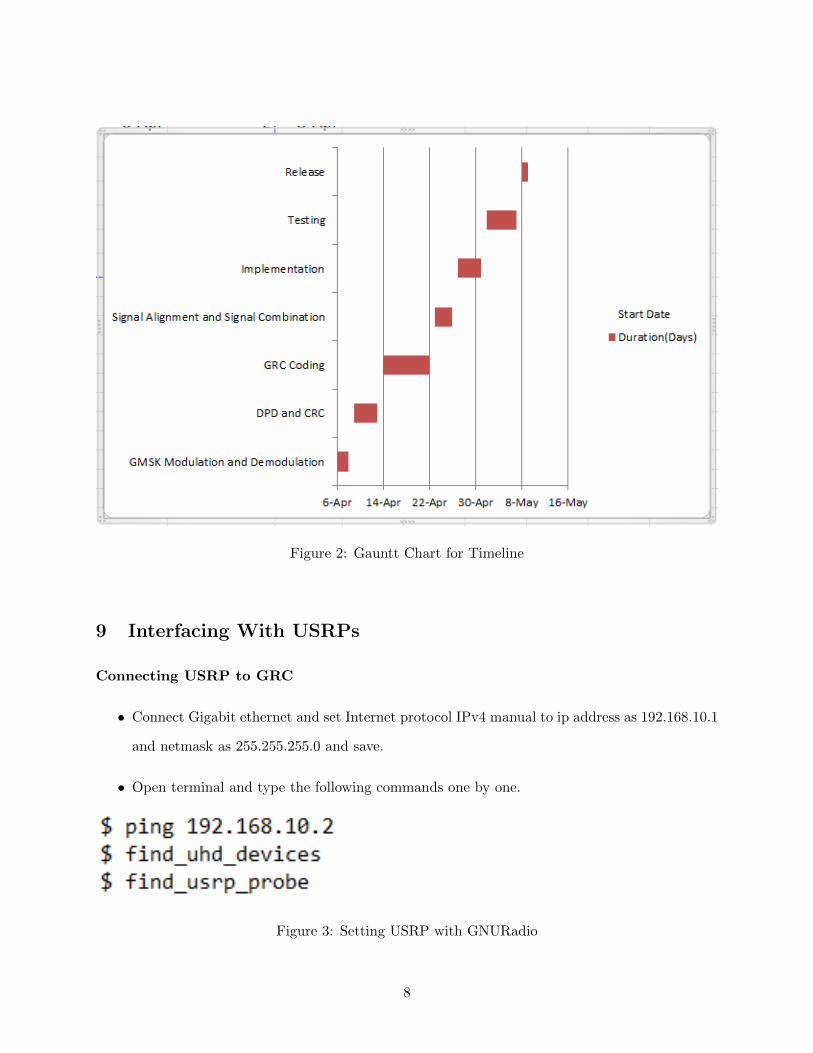
Figure 2: Gauntt Chart for Timeline
9 Interfacing With USRPs
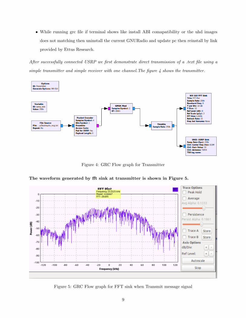
Connecting USRP to GRC
• Connect Gigabit ethernet and set Internet protocol IPv4 manual to ip address as 192.168.10.1
and netmask as 255.255.255.0 and save.
• Open terminal and type the following commands one by one.
Figure 3: Setting USRP with GNURadio
8
• While running grc file if terminal shows like install ABI comapatibility or the uhd images
does not matching then uninstall the current GNURadio and update pc then reinstall by link
provided by Ettus Research.
After successfully connected USRP we first demonstrate direct transmission of a .text file using a
simple transmitter and simple receiver with one channel.The figure 4 shows the transmitter.
Figure 4: GRC Flow graph for Transmitter
The waveform generated by fft sink at transmitter is shown in Figure 5.
Figure 5: GRC Flow graph for FFT sink when Transmit message signal
9
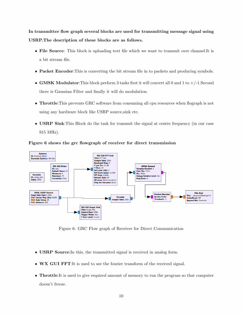
In transmitter flow graph several blocks are used for transmitting message signal using
USRP.The description of these blocks are as follows.
• File Source: This block is uploading text file which we want to transmit over channel.It is
a bit stream file.
• Packet Encoder:This is converting the bit stream file in to packets and producing symbols.
• GMSK Modulator:This block perform 3 tasks first it will convert all 0 and 1 to +/-1.Second
there is Gaussian Filter and finally it will do modulation.
• Throttle:This prevents GRC software from consuming all cpu resources when flograph is not
using any hardware block like USRP source,sink etc.
• USRP Sink:This Block do the task for transmit the signal at centre frequency (in our case
915 MHz).
Figure 6 shows the grc flowgraph of receiver for direct transmission
Figure 6: GRC Flow graph of Receiver for Direct Communication
• USRP Source:In this, the transmitted signal is received in analog form.
• WX GUI FFT:It is used to see the fourier transform of the received signal.
• Throttle:It is used to give required amount of memory to run the program so that computer
doesn’t freeze.
10
• GMSK Demodulator: It collects the phase information of incoming packets. B) Clock
Recovery : It synchronize the symbols. C) Slicer It is used for symbol decision.Packet Decoder:
In this, Data are extracted from the packet.
• Packet Decoder:In this, Data are extracted from the packet.
• File Sink:The extracted data are sent into a file where they are saved.
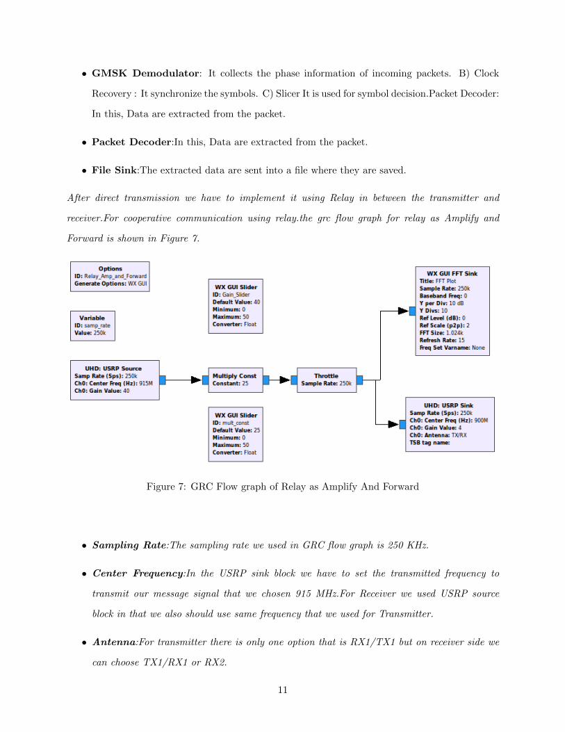
After direct transmission we have to implement it using Relay in between the transmitter and
receiver.For cooperative communication using relay.the grc flow graph for relay as Amplify and
Forward is shown in Figure 7.
Figure 7: GRC Flow graph of Relay as Amplify And Forward
• Sampling Rate:The sampling rate we used in GRC flow graph is 250 KHz.
• Center Frequency:In the USRP sink block we have to set the transmitted frequency to
transmit our message signal that we chosen 915 MHz.For Receiver we used USRP source
block in that we also should use same frequency that we used for Transmitter.
• Antenna:For transmitter there is only one option that is RX1/TX1 but on receiver side we
can choose TX1/RX1 or RX2.
11
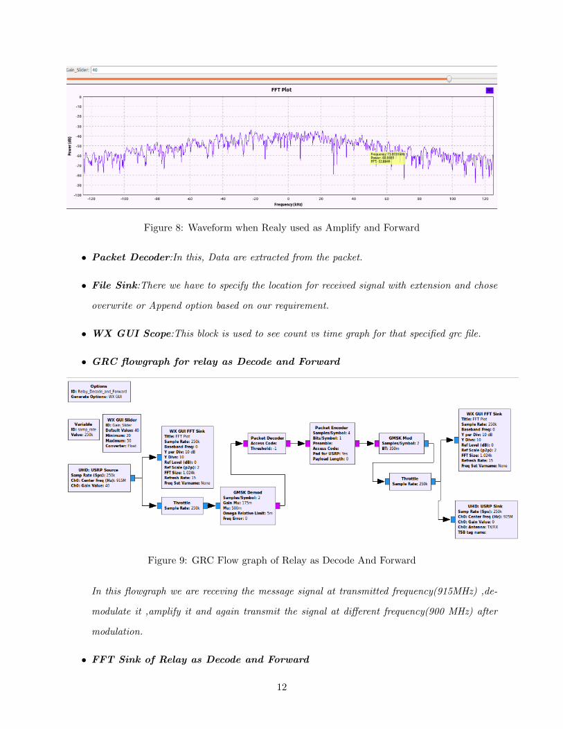
Figure 8: Waveform when Realy used as Amplify and Forward
• Packet Decoder:In this, Data are extracted from the packet.
• File Sink:There we have to specify the location for received signal with extension and chose
overwrite or Append option based on our requirement.
• WX GUI Scope:This block is used to see count vs time graph for that specified grc file.
• GRC flowgraph for relay as Decode and Forward
Figure 9: GRC Flow graph of Relay as Decode And Forward
In this flowgraph we are receving the message signal at transmitted frequency(915MHz) ,de-
modulate it ,amplify it and again transmit the signal at different frequency(900 MHz) after
modulation.
• FFT Sink of Relay as Decode and Forward
12
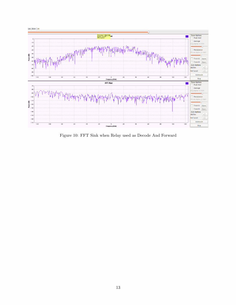
Figure 10: FFT Sink when Relay used as Decode And Forward
13
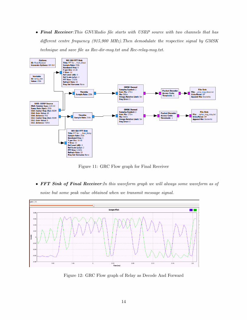
• Final Receiver:This GNURadio file starts with USRP source with two channels that has
different centre frequency (915,900 MHz).Then demodulate the respective signal by GMSK
technique and save file as Rec-dir-msg.txt and Rec-relay-msg.txt.
Figure 11: GRC Flow graph for Final Receiver
• FFT Sink of Final Receiver:In this waveform graph we will always some waveform as of
noise but some peak value obtained when we transmit message signal.
Figure 12: GRC Flow graph of Relay as Decode And Forward
14
10 Lessons Learned
Throughout this project we understand how to setup USRP in resective uhd device.By performing
the cooperative communication using relay we understand how a file transmission takes place and
at what frequency suitable for what type of message file transmission.We also learned how GMSK
works.
11 Conclusion and Future scope
In this we understood that a usrp can do one thing at a time means it can not do transmission
and as a reception simultaneously.For very short message signal the transmission it not taking
place without repeat mode. This implementation of Cooperative communication using Relay at lab
environment demonstrates basic file transmission using hardware and software based platform.
for future implementation we have to deal with more obstacle destruction so we can use multiple
relays for less distortion.
we can use OFDM modulation technique for better signal quality and efficient spectrum of received
signal.
References
[1] National Instruments,
http://www.ni.com/en-in/shop/select/software-defined-radio-device
[2] GNU Radio
http://wiki.gnuradio.org/index.php
https://www.youtube.com/watch?v=rZ0JlDIwBxo
[3] Opencircuit Design,
https://www.opencircuitdesign.com
[4] Relay Network,
https://en.wikipedia.org/wiki/Relay
15
12 Appendices
Here is the detail of Hardware devices used for our project
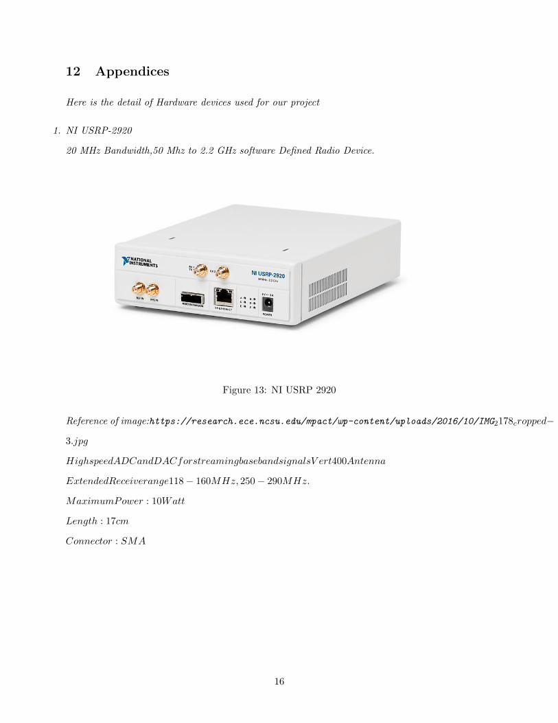
1. NI USRP-2920
20 MHz Bandwidth,50 Mhz to 2.2 GHz software Defined Radio Device.
Figure 13: NI USRP 2920
Reference of image:https://research.ece.ncsu.edu/mpact/wp-content/uploads/2016/10/IMG2178cropped−
3.jpg
HighspeedADCandDACforstreamingbasebandsignalsV ert400Antenna
ExtendedReceiverange118 − 160MHz, 250 − 290MHz.
MaximumPower : 10Watt
Length : 17cm
Connector : SMA
16


![EE-304 Electrical Network Theory [Class Notes1] - 2013](https://img.pdfslide.us/doc/110x75/55859381d8b42ac76d8b4a31/ee-304-electrical-network-theory-class-notes1-2013.jpg)