Embed Size (px)
Citation preview
EE 221 CIRCUITS IIChapter 12Chapter 12ThreeThree--Phase CircuitPhase Circuit
1

THREE-PHASE CIRCUITS CHAPTER 12
12.1 What is a Three-Phase Circuit?12.2 Balanced Three-Phase Voltages12.3 Balanced Three-Phase Connection12.4 Power in a Balanced System12.5 Unbalanced Three-Phase Systems12.6 Application – Residential Wiring
2
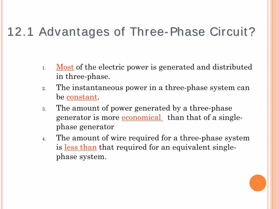
1. Most of the electric power is generated and distributed in three-phase.
2. The instantaneous power in a three-phase system can be constant.
3. The amount of power generated by a three-phase generator is more economical than that of a single-phase generator
4. The amount of wire required for a three-phase system is less than that required for an equivalent single-phase system.
3
12.1 Advantages of Three12.1 Advantages of Three--Phase Circuit?Phase Circuit?
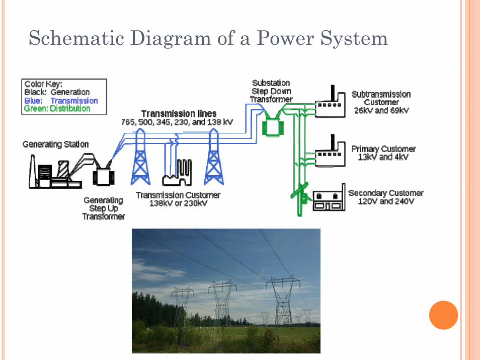
Schematic Diagram of a Power System
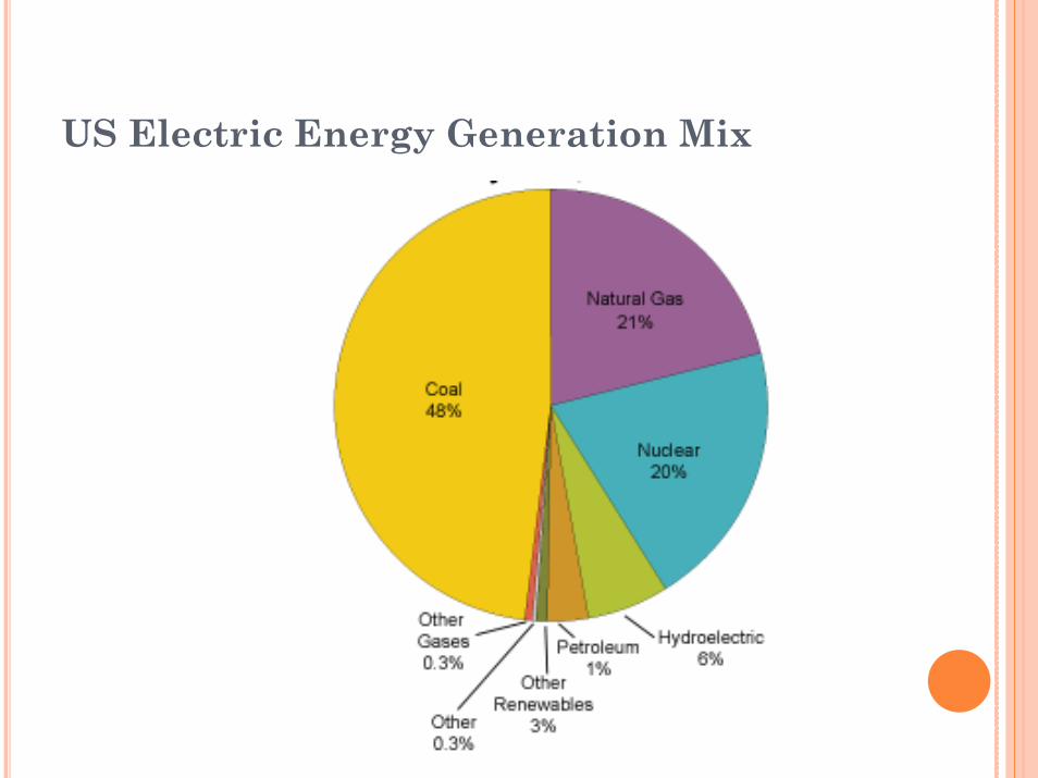
US Electric Energy Generation Mix
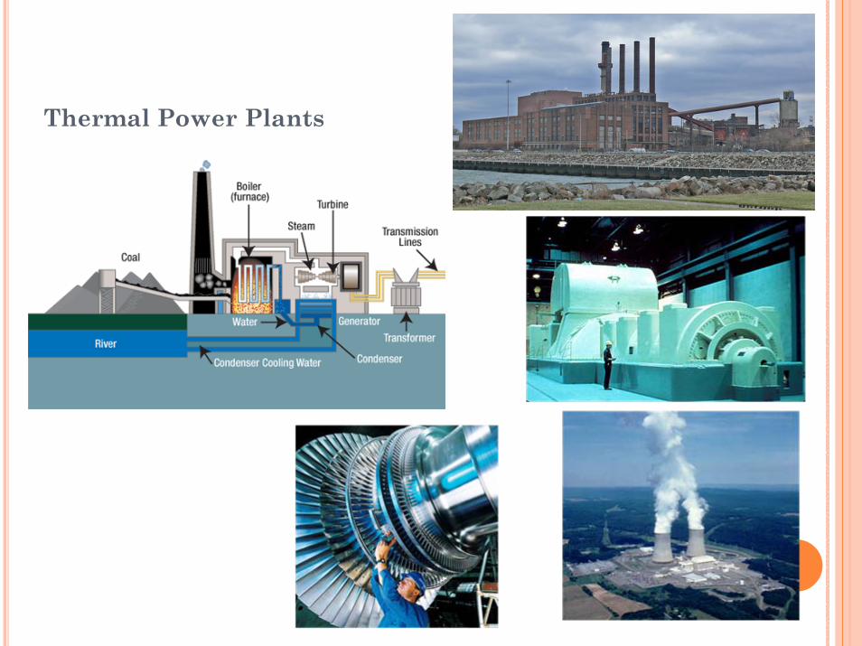
Thermal Power Plants
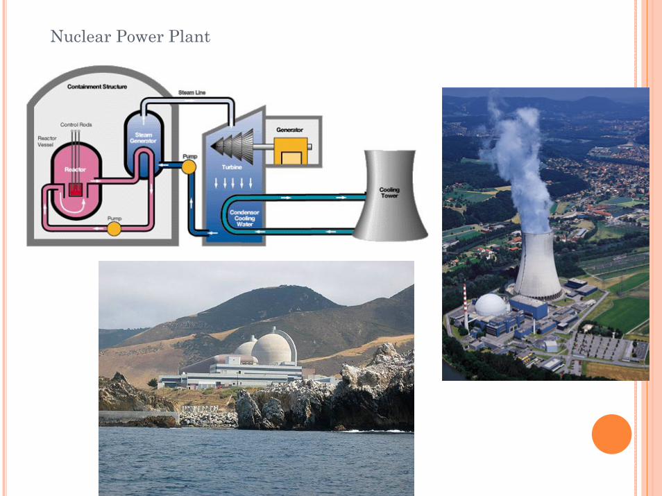
Nuclear Power Plant
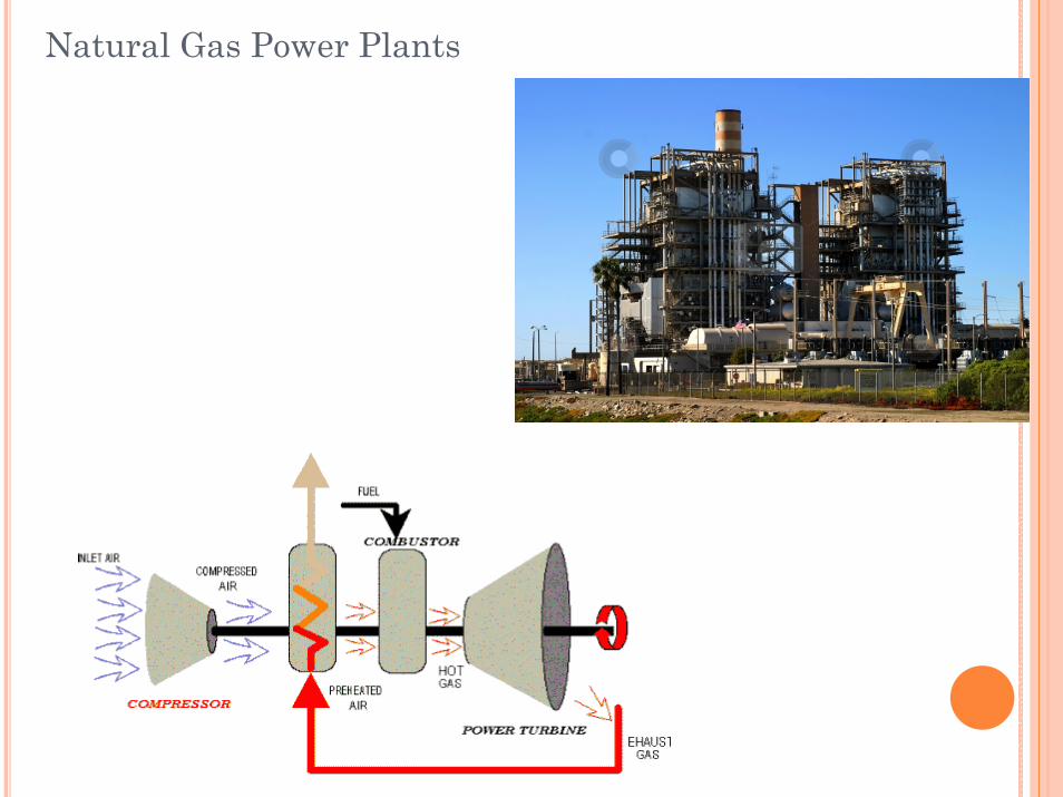
Natural Gas Power Plants
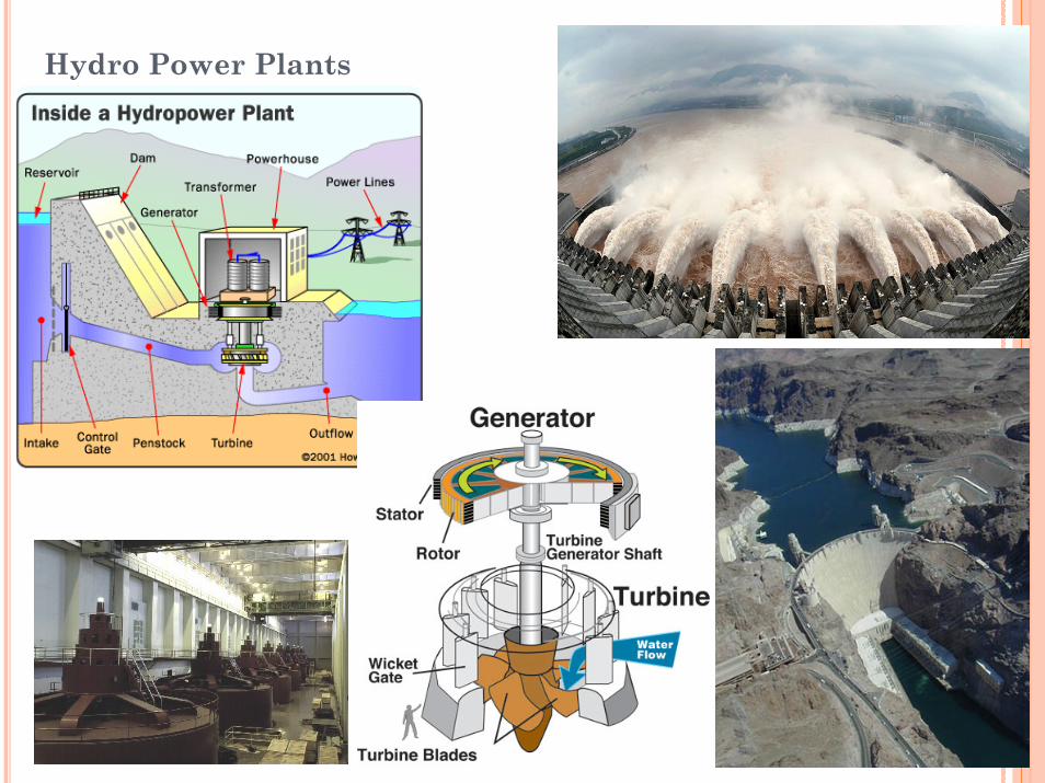
Hydro Power Plants
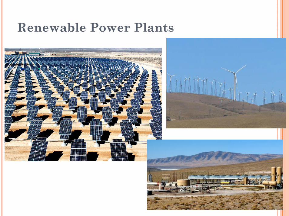
Renewable Power Plants
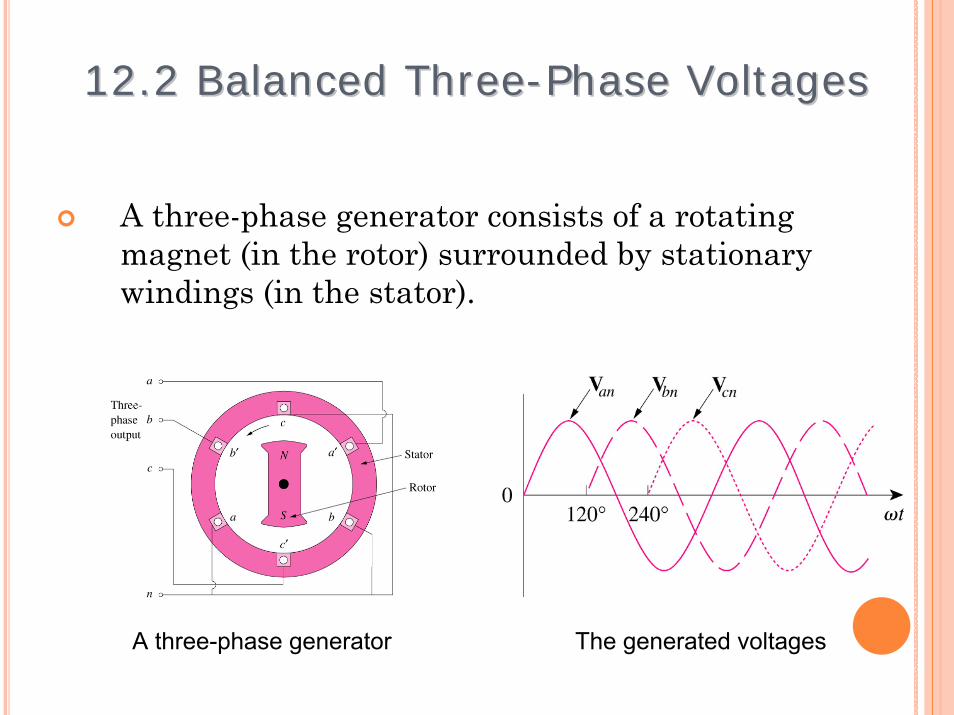
A three-phase generator consists of a rotating magnet (in the rotor) surrounded by stationary windings (in the stator).
11
12.2 Balanced Three12.2 Balanced Three--Phase Voltages Phase Voltages
A three-phase generator The generated voltages
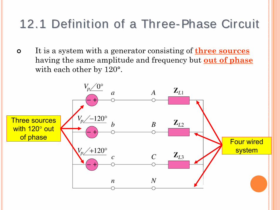
It is a system with a generator consisting of three sourceshaving the same amplitude and frequency but out of phasewith each other by 120°.
12
12.1 Definition of a Three12.1 Definition of a Three--Phase CircuitPhase Circuit
Three sources with 120° out
of phase Four wired system
Two possible configurations:
13
12.2 Balanced Three12.2 Balanced Three--Phase Voltages Phase Voltages
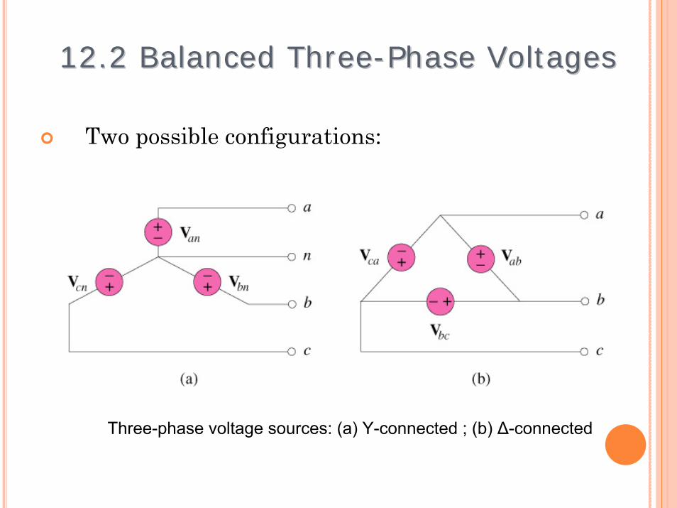
Three-phase voltage sources: (a) Y-connected ; (b) Δ-connected
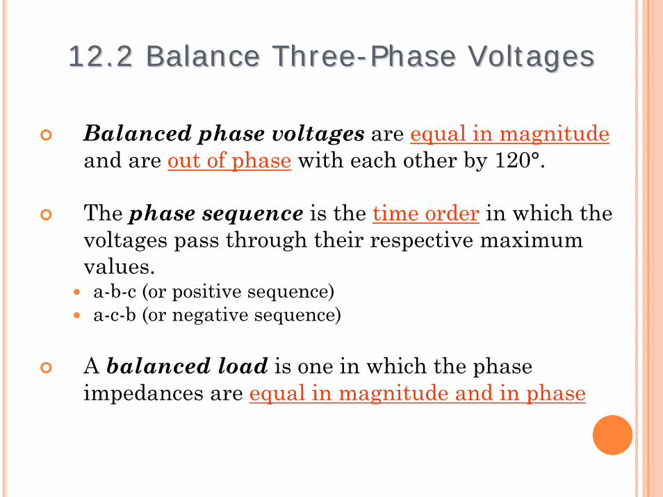
Balanced phase voltages are equal in magnitudeand are out of phase with each other by 120°.
The phase sequence is the time order in which the voltages pass through their respective maximum values.a-b-c (or positive sequence)a-c-b (or negative sequence)
A balanced load is one in which the phase impedances are equal in magnitude and in phase
14
12.2 Balance Three12.2 Balance Three--Phase Voltages Phase Voltages

Example 1
Determine the phase sequence of the set of voltages.
)110cos(200)230cos(200
)10cos(200
°−=°−=
°+=
tvtvtv
cn
bn
an
ωωω
15
12.2 Balance Three12.2 Balance Three--Phase Voltages Phase Voltages

Solution:
The voltages can be expressed in phasor form as
We notice that Van leads Vcn by 120° and Vcn in turn leads Vbn by 120°.
Hence, we have an a-c-b sequence (or negative sequence).
V 110200VV 230200V
V 10200V
°−∠=°−∠=
°∠=
cn
bn
an
16
12.2 Balanced Three12.2 Balanced Three--Phase Voltages Phase Voltages
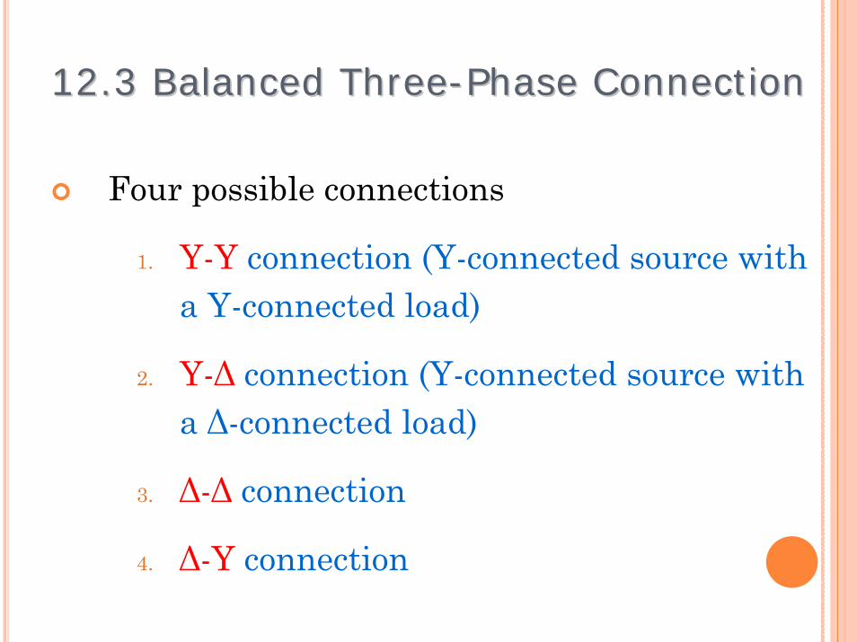
Four possible connections
1. Y-Y connection (Y-connected source with a Y-connected load)
2. Y-Δ connection (Y-connected source with a Δ-connected load)
3. Δ-Δ connection
4. Δ-Y connection17
12.3 Balanced Three12.3 Balanced Three--Phase Connection Phase Connection
cabcabL
cnbnanp
pL
V
V
VV
VVV
VVV
where, 3
===
===
=
18
12.3 Balance Three12.3 Balance Three--Phase Connection Phase Connection
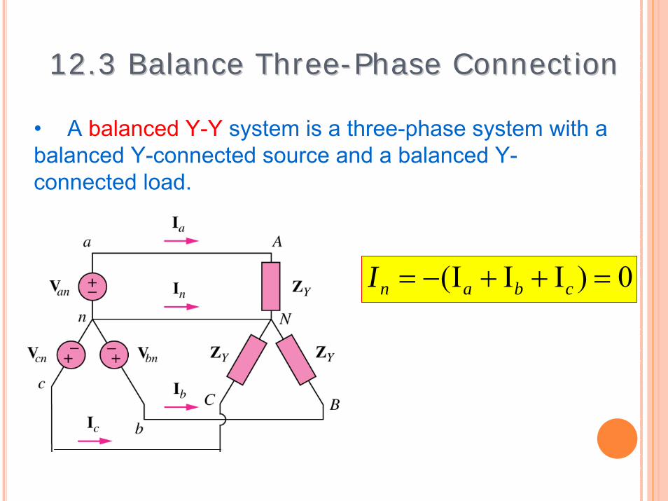
• A balanced Y-Y system is a three-phase system with a balanced Y-connected source and a balanced Y-connected load.
0)III( =++−= cbanI
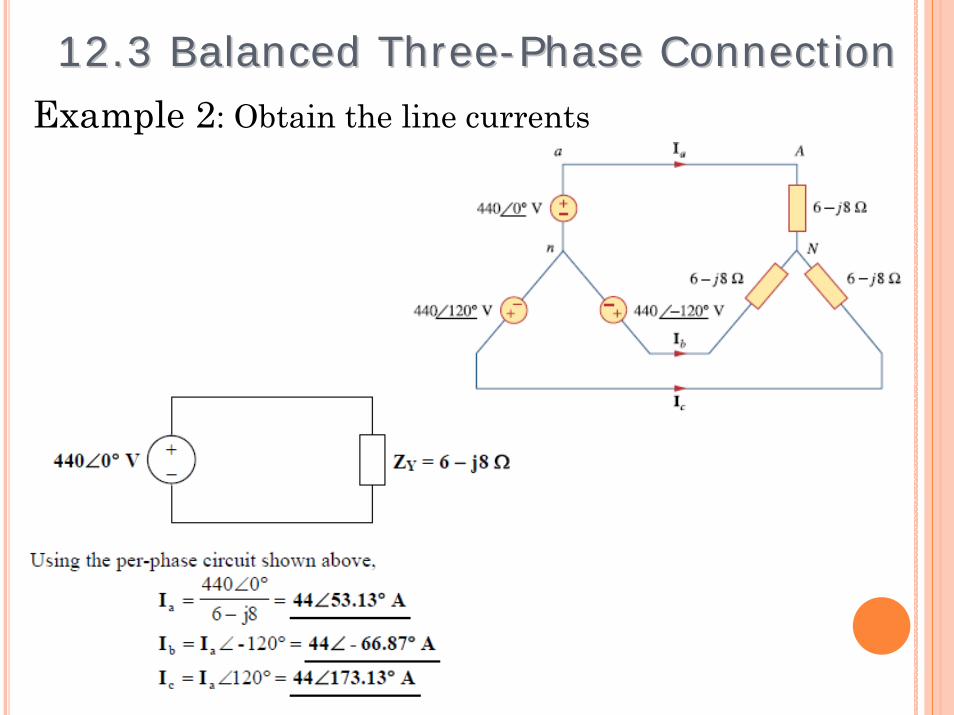
Example 2: Obtain the line currents
19
12.3 Balanced Three12.3 Balanced Three--Phase Connection Phase Connection
20
CABCABp
cbaL
pL
I
I
II
III
III
where, 3
===
===
=
12.3 Balanced Three12.3 Balanced Three--Phase ConnectionPhase Connection
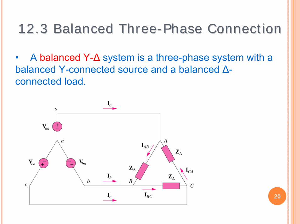
• A balanced Y-Δ system is a three-phase system with a balanced Y-connected source and a balanced Δ-connected load.
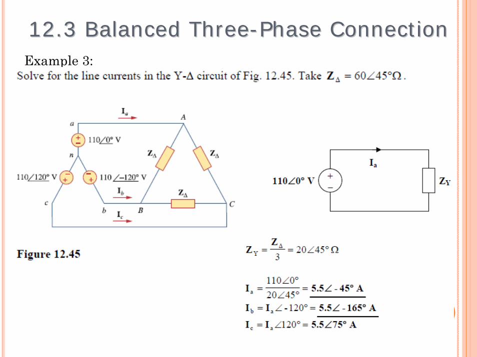
Example 3:
21
12.3 Balanced Three12.3 Balanced Three--Phase ConnectionPhase Connection
22
12.3 Balanced Three12.3 Balanced Three--Phase Connection Phase Connection
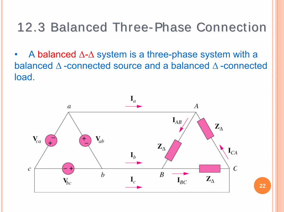
• A balanced Δ-Δ system is a three-phase system with a balanced Δ -connected source and a balanced Δ -connected load.

23
Example 4:
12.3 Balance Three12.3 Balance Three--Phase Connection Phase Connection
24
12.3 Balanced Three12.3 Balanced Three--Phase Connection Phase Connection
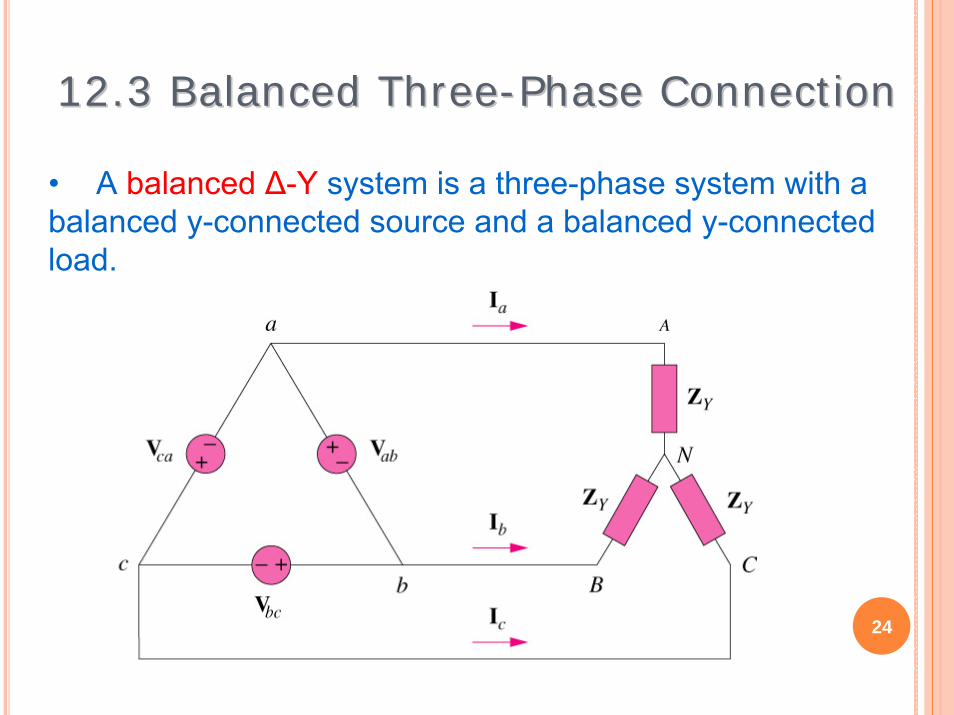
• A balanced Δ-Y system is a three-phase system with a balanced y-connected source and a balanced y-connected load.
25
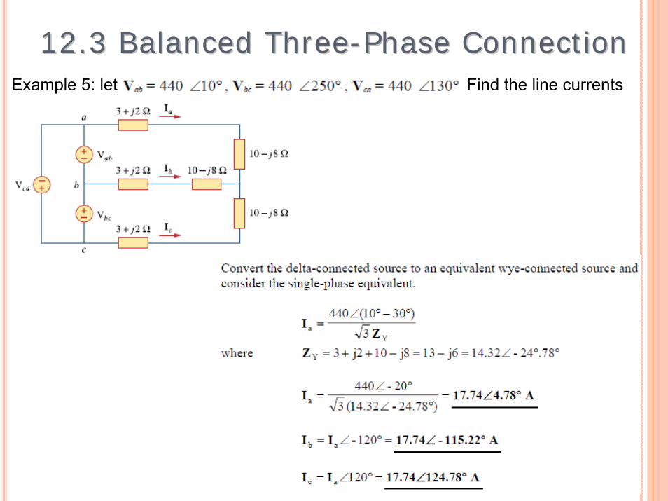
Example 5: let Find the line currents
12.3 Balanced Three12.3 Balanced Three--Phase Connection Phase Connection
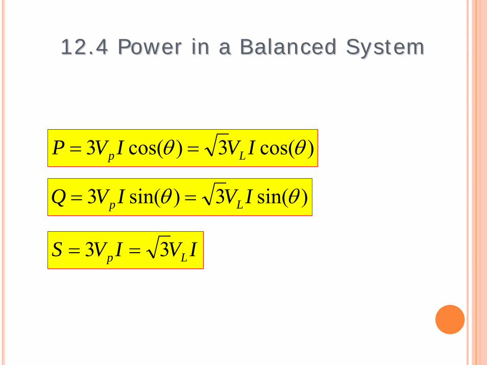
)cos(3)cos(3 θθ IVIVP Lp ==
26
12.4 Power in a Balanced System 12.4 Power in a Balanced System
)sin(3)sin(3 θθ IVIVQ Lp ==
IVIVS Lp 33 ==
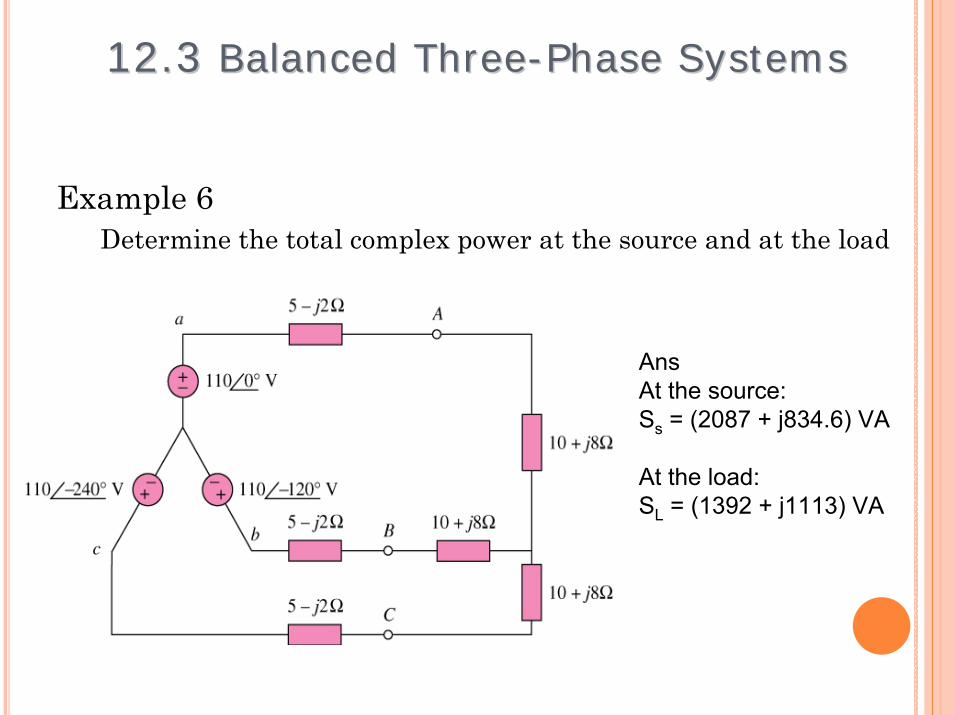
Example 6Determine the total complex power at the source and at the load
27
12.3 12.3 Balanced ThreeBalanced Three--Phase Systems Phase Systems
AnsAt the source:Ss = (2087 + j834.6) VA
At the load:SL = (1392 + j1113) VA
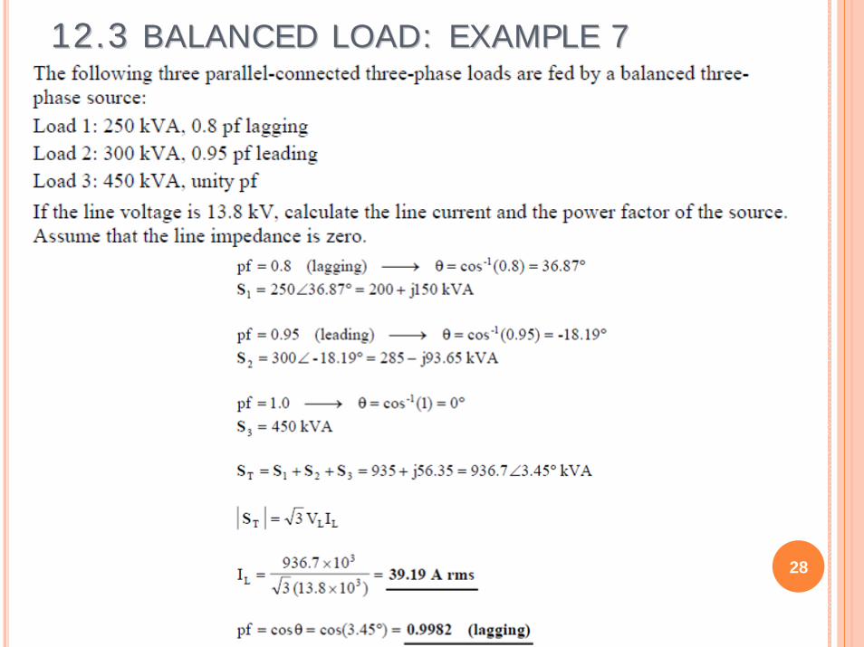
12.3 12.3 BALANCED LOAD: EXAMPLE 7BALANCED LOAD: EXAMPLE 7
28

)III(I
,ZVI ,
ZVI ,
ZVI
cban
C
CNc
B
BNb
A
ANa
++−=
===
29
• The total power is not simply three times the power in one phase but the sum of the powers in the three phases.
• To calculate power in an unbalanced three-phase system requires that we find the power in each phase.
12.5 Unbalanced Three12.5 Unbalanced Three--Phase Systems Phase Systems
• An unbalanced system is due to unbalanced voltage sources or an unbalanced load.
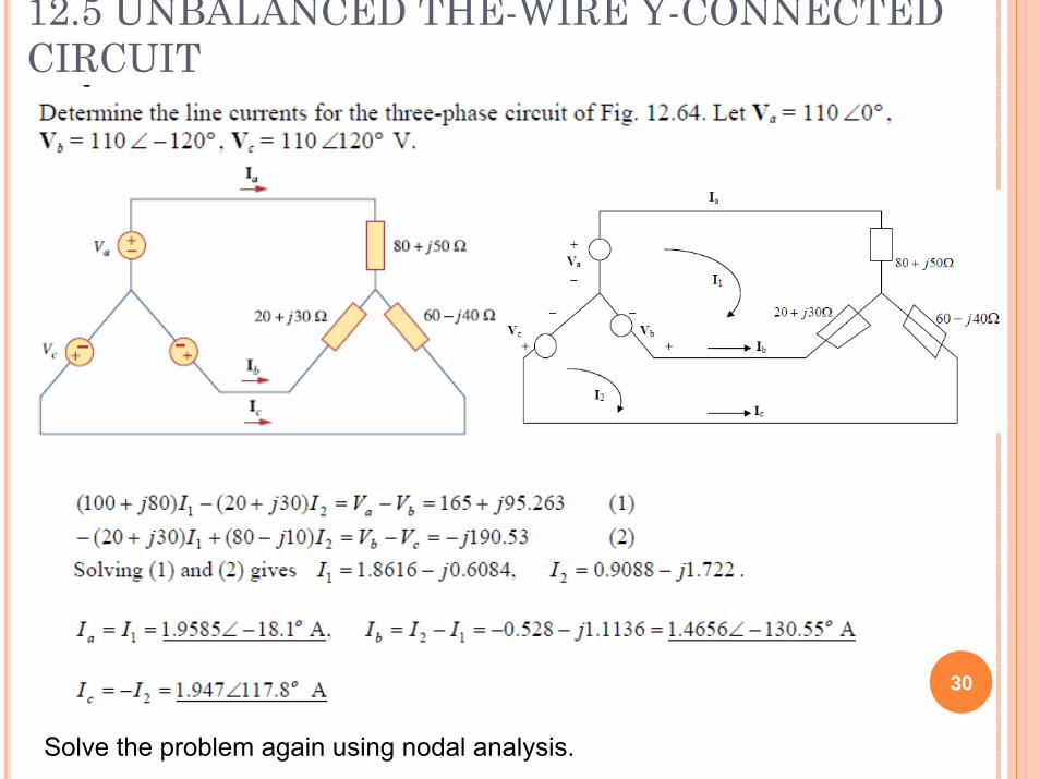
12.5 UNBALANCED THE-WIRE Y-CONNECTED CIRCUIT
30
Solve the problem again using nodal analysis.

31
12.5 UNBALANCED THE WIRE Δ CONNECTED CIRCUITCalculate the line currents and total real and reactive power supplied by the source:
Rework the problem using a simpler method
32
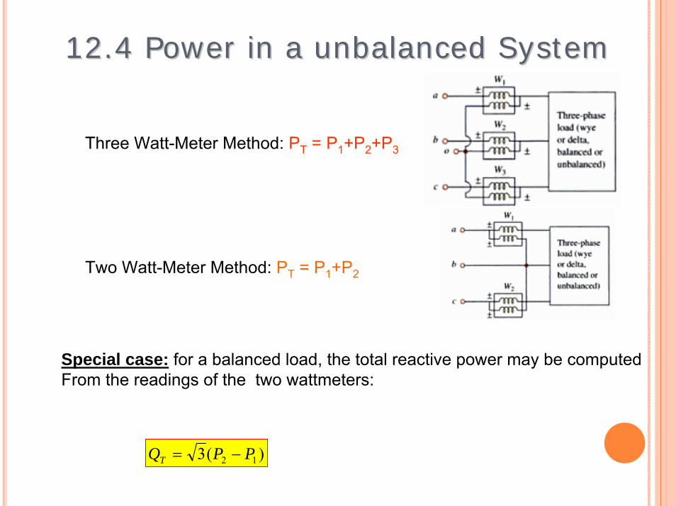
12.4 Power in a unbalanced System 12.4 Power in a unbalanced System
)(3 12 PPQT −=
Three Watt-Meter Method: PT = P1+P2+P3
Two Watt-Meter Method: PT = P1+P2
Special case: for a balanced load, the total reactive power may be computed From the readings of the two wattmeters:

2-WATTMETER METHOD
33
The unbalanced load is supplied by a balanced source such that Vab = 208�0°V with positive phase sequence. Calculate the reading of each wattmeter.
Verify the answer by computing the power consumed by each resistor
34
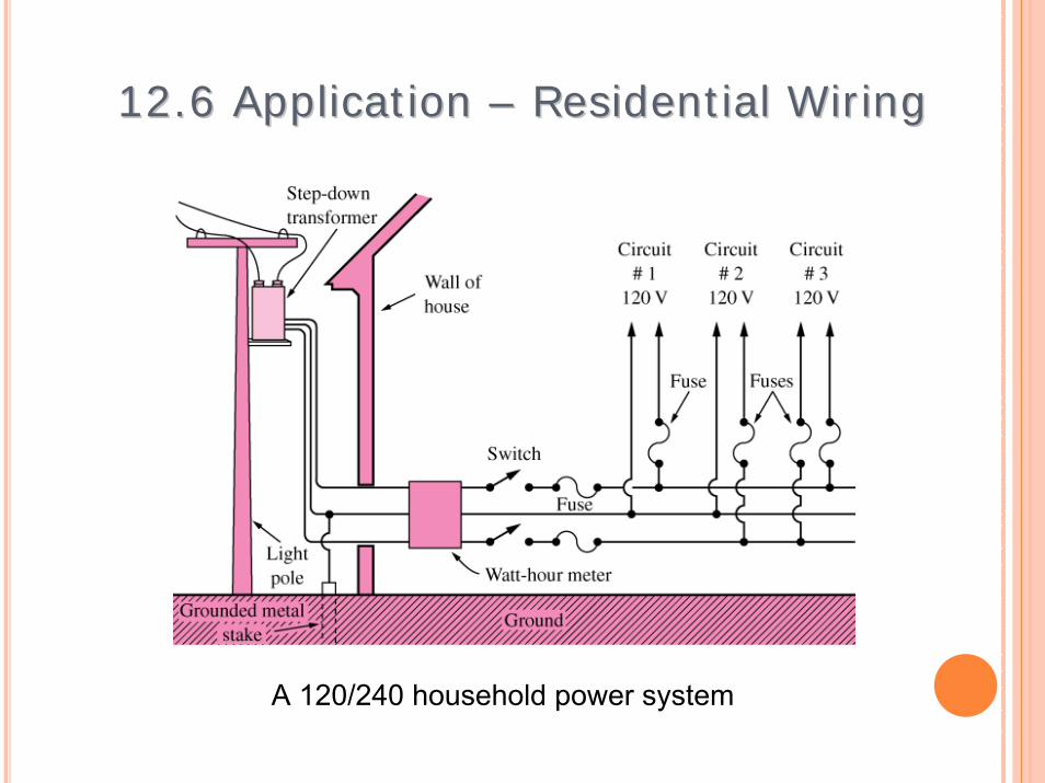
12.6 Application 12.6 Application –– Residential Wiring Residential Wiring
A 120/240 household power system
35
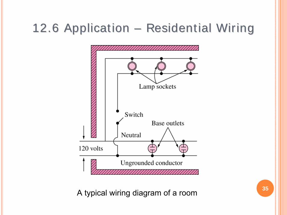
12.6 Application 12.6 Application –– Residential Wiring Residential Wiring
A typical wiring diagram of a room
36
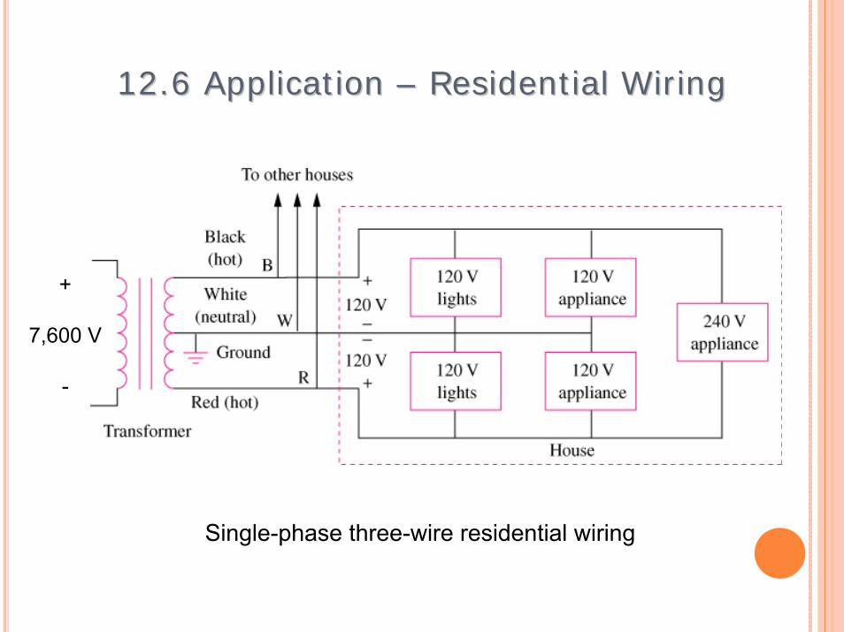
12.6 Application 12.6 Application –– Residential Wiring Residential Wiring
Single-phase three-wire residential wiring
+
7,600 V
-

37
12.6 Application 12.6 Application –– Residential Wiring Residential Wiring

UTILITY APPLICATION OF CAPACITORS FOR VOLTAGE REGULATION AND POWER TRANSFER
38
Capacitors are placed in series with high Voltage transmission lines to improve voltage Regulation and power transfer capability
Capacitor are also used in medium voltage power Distribution lines to regulate voltage and reduce power losses
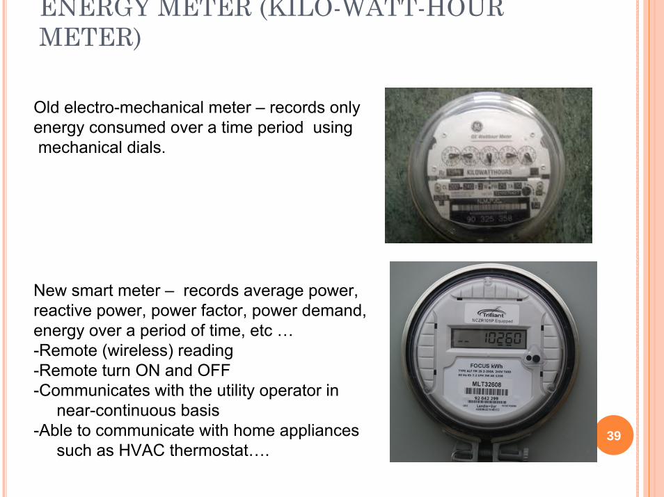
ENERGY METER (KILO-WATT-HOUR METER)
39
Old electro-mechanical meter – records onlyenergy consumed over a time period usingmechanical dials.
New smart meter – records average power, reactive power, power factor, power demand, energy over a period of time, etc …-Remote (wireless) reading-Remote turn ON and OFF-Communicates with the utility operator in
near-continuous basis-Able to communicate with home appliances
such as HVAC thermostat….