Embed Size (px)
Citation preview
11.1
Unit 11
Adders & Arithmetic Circuits
11.2
Learning Outcomes
• I understand what gates are used to design half and full adders
• I can build larger arithmetic circuits from smaller building blocks

11.3
ADDERS
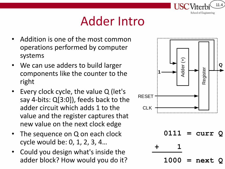
11.4
Adder Intro• Addition is one of the most common
operations performed by computer systems
• We can use adders to build larger components like the counter to the right
• Every clock cycle, the value Q (let's say 4-bits: Q[3:0]), feeds back to the adder circuit which adds 1 to the value and the register captures that new value on the next clock edge
• The sequence on Q on each clock cycle would be: 0, 1, 2, 3, 4…
• Could you design what's inside the adder block? How would you do it?
0111
+ 1
1000
= curr Q
= next Q
Re
gis
ter
1
Add
er
(+)
Q
RESET
CLK
11.5
Adder Intro
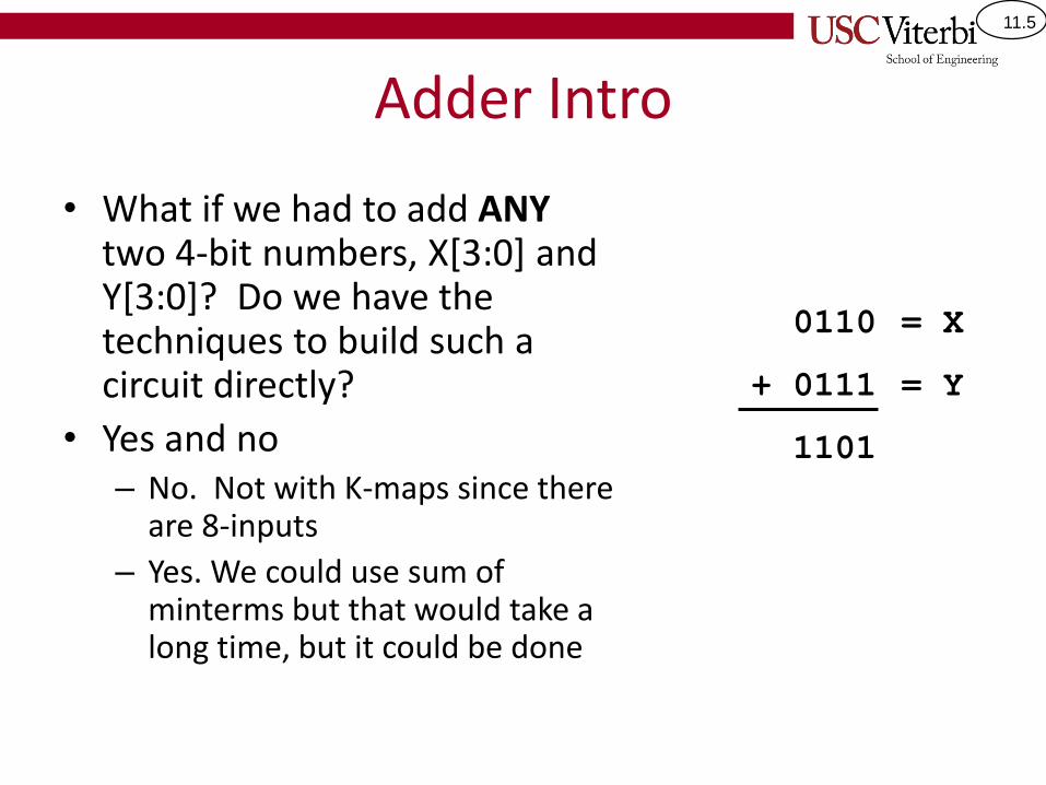
• What if we had to add ANY two 4-bit numbers, X[3:0] and Y[3:0]? Do we have the techniques to build such a circuit directly?
• Yes and no– No. Not with K-maps since there
are 8-inputs
– Yes. We could use sum of minterms but that would take a long time, but it could be done
0110
+ 0111
1101
= X
= Y
11.6
Adder Intro
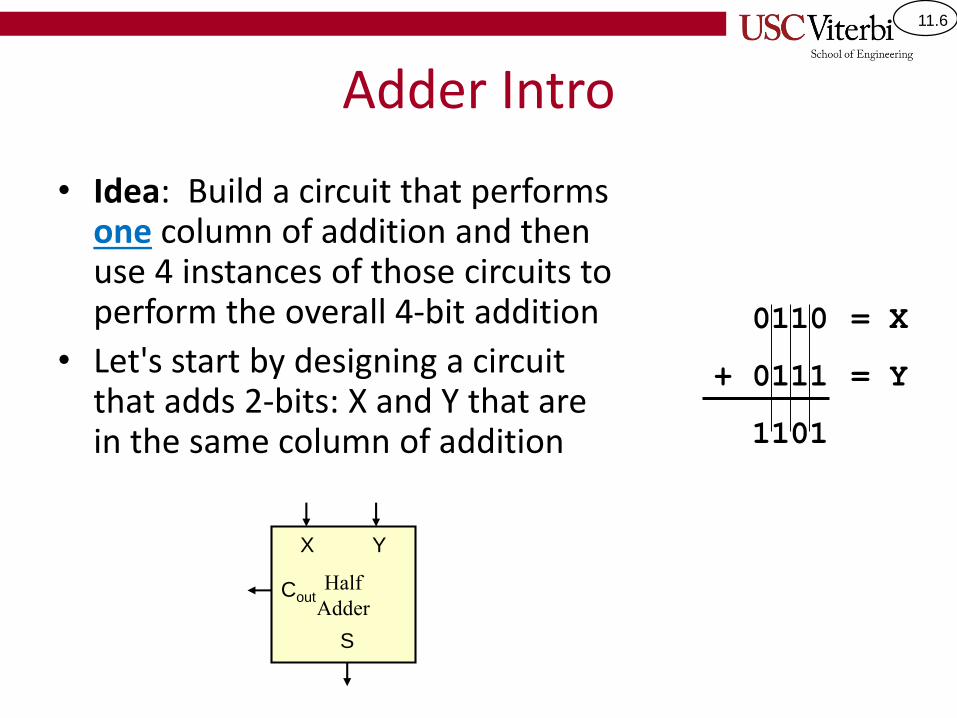
• Idea: Build a circuit that performs one column of addition and then use 4 instances of those circuits to perform the overall 4-bit addition
• Let's start by designing a circuit that adds 2-bits: X and Y that are in the same column of addition
0110
+ 0111
1101
= X
= Y
Half
Adder
X Y
S
Cout
11.7
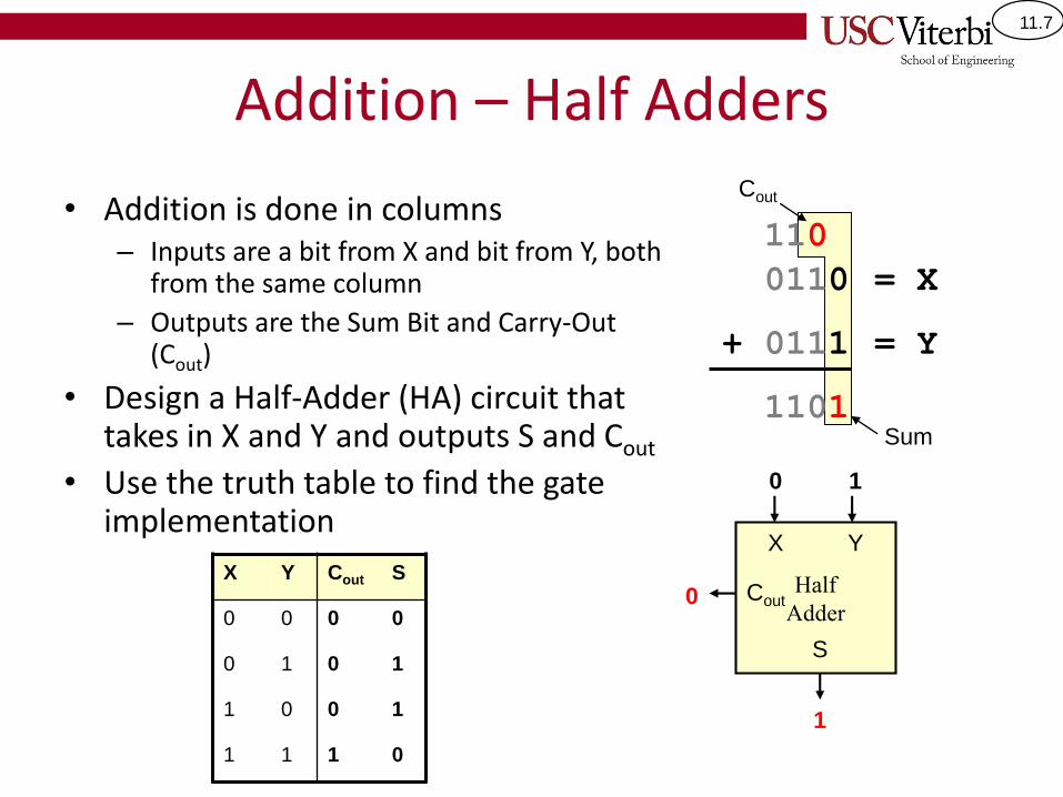
Addition – Half Adders
• Addition is done in columns– Inputs are a bit from X and bit from Y, both
from the same column
– Outputs are the Sum Bit and Carry-Out (Cout)
• Design a Half-Adder (HA) circuit that takes in X and Y and outputs S and Cout
• Use the truth table to find the gate implementation
0110
+ 0111
1101
= X
= Y
110
Half
Adder
X Y
S
Cout
Cout
Sum
0 1
1
0X Y Cout S
0 0 0 0
0 1 0 1
1 0 0 1
1 1 1 0
11.8
Problem With Half Adders
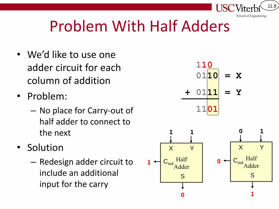
• We’d like to use one adder circuit for each column of addition
• Problem:
– No place for Carry-out of half adder to connect to the next
• Solution
– Redesign adder circuit to include an additional input for the carry
0110
+ 0111
1101
= X
= Y
110
Half
Adder
X Y
S
Cout
0 1
1
0Half
Adder
X Y
S
Cout
1 1
0
1
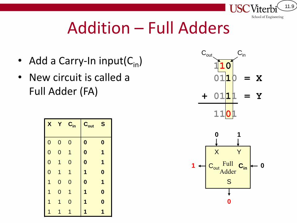
11.9
Addition – Full Adders
• Add a Carry-In input(Cin)
• New circuit is called a Full Adder (FA)
0110
+ 0111
1101
= X
= Y
110
Full
Adder
X Y
Cin
S
Cout
Cout Cin
0 1
0
1 0
X Y Cin Cout S
0 0 0 0 0
0 0 1 0 1
0 1 0 0 1
0 1 1 1 0
1 0 0 0 1
1 0 1 1 0
1 1 0 1 0
1 1 1 1 1
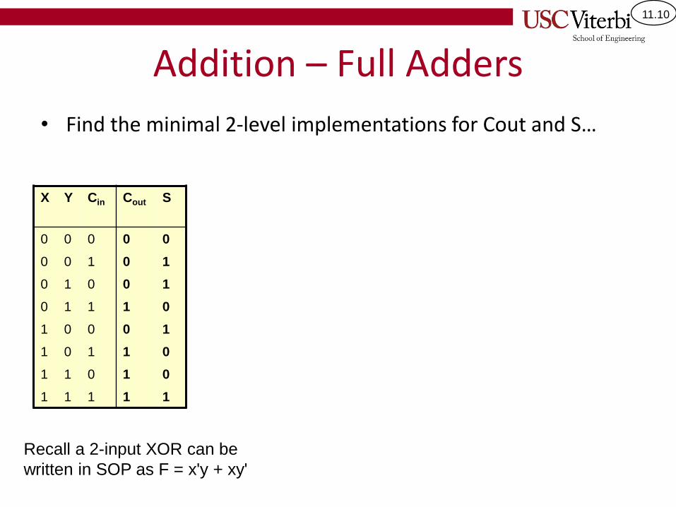
11.10
Addition – Full Adders
• Find the minimal 2-level implementations for Cout and S…
X Y Cin Cout S
0 0 0 0 0
0 0 1 0 1
0 1 0 0 1
0 1 1 1 0
1 0 0 0 1
1 0 1 1 0
1 1 0 1 0
1 1 1 1 1
Recall a 2-input XOR can be
written in SOP as F = x'y + xy'
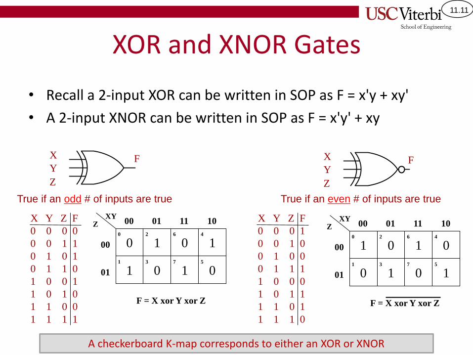
11.11
XOR and XNOR Gates
• Recall a 2-input XOR can be written in SOP as F = x'y + xy'
• A 2-input XNOR can be written in SOP as F = x'y' + xy
True if an odd # of inputs are true True if an even # of inputs are true
X Y Z F
0 0 0 0
0 0 1 1
0 1 0 1
0 1 1 0
1 0 0 1
1 0 1 0
1 1 0 0
1 1 1 1
X
Y
Z
F
X Y Z F
0 0 0 1
0 0 1 0
0 1 0 0
0 1 1 1
1 0 0 0
1 0 1 1
1 1 0 1
1 1 1 0
X
Y
Z
F
0 1 0 1
1 0 1 0
XYZ 00 01 11 10
00
01
0
1
2
3
6
7
4
5
F = X xor Y xor Z
1 0 1 0
0 1 0 1
XYZ 00 01 11 10
00
01
0
1
2
3
6
7
4
5
F = X xor Y xor Z
A checkerboard K-map corresponds to either an XOR or XNOR
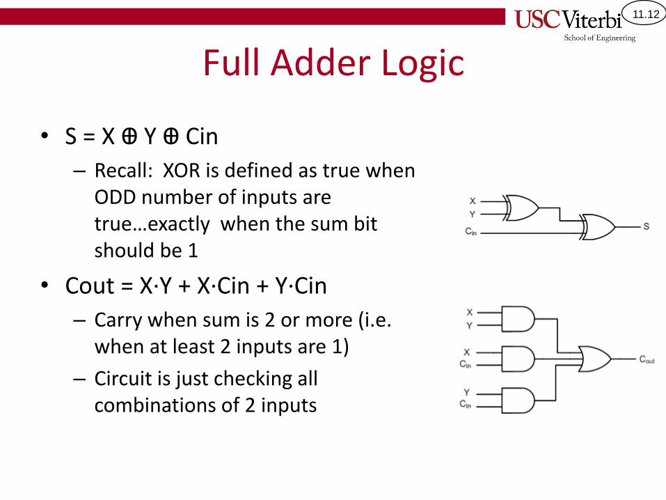
11.12
Full Adder Logic
• S = X Ꚛ Y Ꚛ Cin
– Recall: XOR is defined as true when ODD number of inputs are true…exactly when the sum bit should be 1
• Cout = X∙Y + X∙Cin + Y∙Cin
– Carry when sum is 2 or more (i.e. when at least 2 inputs are 1)
– Circuit is just checking all combinations of 2 inputs
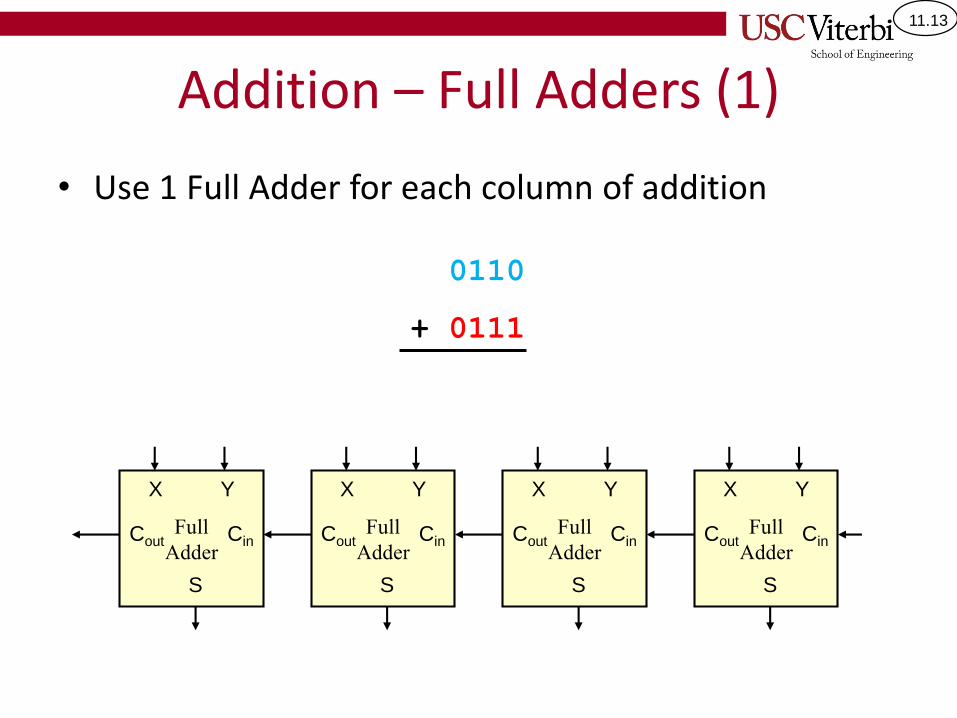
11.13
Addition – Full Adders (1)
• Use 1 Full Adder for each column of addition
0110
+ 0111
Full
Adder
X Y
Cin
S
CoutFull
Adder
X Y
Cin
S
CoutFull
Adder
X Y
Cin
S
CoutFull
Adder
X Y
Cin
S
Cout
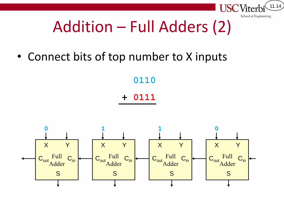
11.14
Addition – Full Adders (2)
• Connect bits of top number to X inputs
0110
+ 0111
Full
Adder
X Y
Cin
S
Cout
0
Full
Adder
X Y
Cin
S
CoutFull
Adder
X Y
Cin
S
CoutFull
Adder
X Y
Cin
S
Cout
110
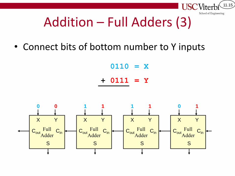
11.15
Addition – Full Adders (3)
• Connect bits of bottom number to Y inputs
0110
+ 0111
= X
= Y
Full
Adder
X Y
Cin
S
Cout
0 1
Full
Adder
X Y
Cin
S
CoutFull
Adder
X Y
Cin
S
CoutFull
Adder
X Y
Cin
S
Cout
1 11 10 0
11.16
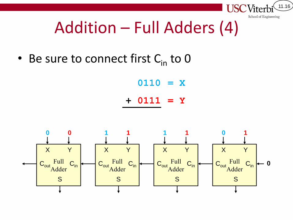
Addition – Full Adders (4)
• Be sure to connect first Cin to 0
0110
+ 0111
= X
= Y
Full
Adder
X Y
Cin
S
Cout
0 1
Full
Adder
X Y
Cin
S
CoutFull
Adder
X Y
Cin
S
CoutFull
Adder
X Y
Cin
S
Cout
1 11 10 0
0
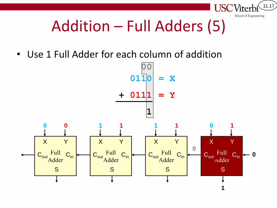
11.17
Addition – Full Adders (5)
• Use 1 Full Adder for each column of addition
0110
+ 0111
1
= X
= Y
Full
Adder
X Y
Cin
S
Cout
0 1
1
00Full
Adder
X Y
Cin
S
CoutFull
Adder
X Y
Cin
S
CoutFull
Adder
X Y
Cin
S
Cout
1 11 10 0
00
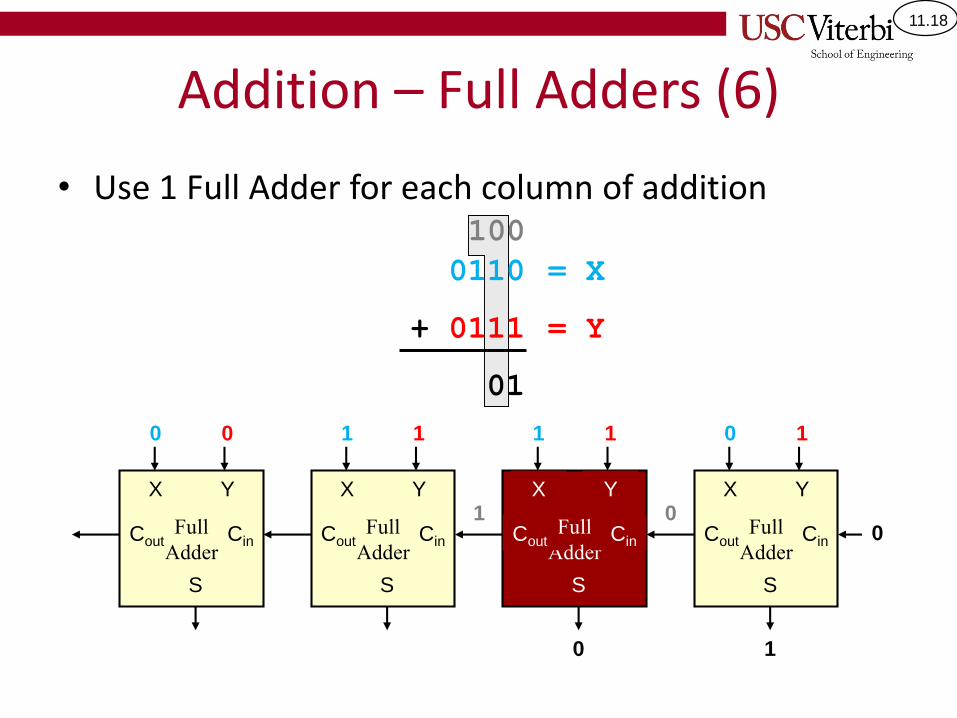
11.18
Addition – Full Adders (6)
• Use 1 Full Adder for each column of addition
Full
Adder
X Y
Cin
S
Cout
1
1
00Full
Adder
X Y
Cin
S
CoutFull
Adder
X Y
Cin
S
CoutFull
Adder
X Y
Cin
S
Cout
1
0
1
10
100
0110
+ 0111
01
= X
= Y
0110
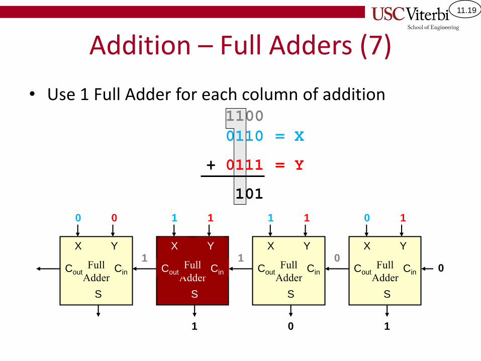
11.19
Addition – Full Adders (7)
• Use 1 Full Adder for each column of addition
Full
Adder
X Y
Cin
S
Cout
1
1
00Full
Adder
X Y
Cin
S
CoutFull
Adder
X Y
Cin
S
CoutFull
Adder
X Y
Cin
S
Cout
1
0
1
1
1
1
0
1100
0110
+ 0111
101
= X
= Y
0110
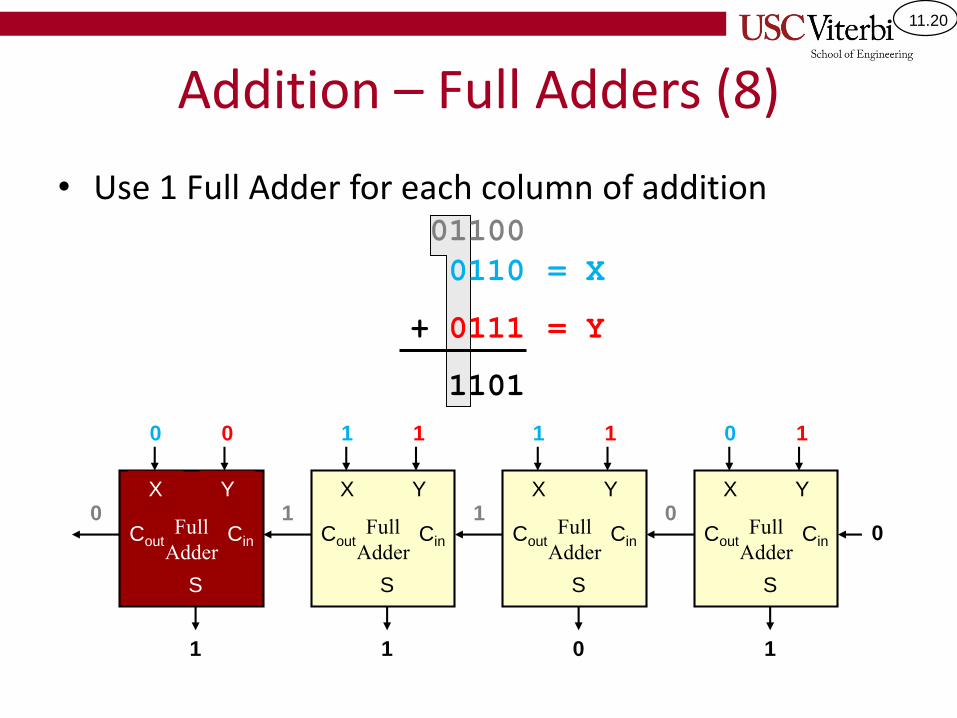
11.20
Addition – Full Adders (8)
• Use 1 Full Adder for each column of addition
Full
Adder
X Y
Cin
S
Cout
1
1
00Full
Adder
X Y
Cin
S
CoutFull
Adder
X Y
Cin
S
CoutFull
Adder
X Y
S
1
0
1
1
1
1
0
1
0
01100
CinCout
0110
+ 0111
1101
= X
= Y
0110
11.21
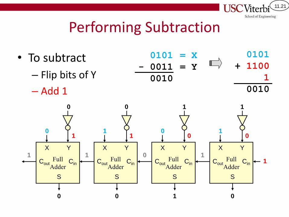
Performing Subtraction
• To subtract
– Flip bits of Y
– Add 1
0101
- 0011
0010
= X
= Y
Full
Adder
X Y
Cin
S
CoutFull
Adder
X Y
Cin
S
CoutFull
Adder
X Y
Cin
S
CoutFull
Adder
X Y
Cin
S
Cout
0101
+ 1100
1
0010
1010
1100
0011
1
0100
1 101
11.22
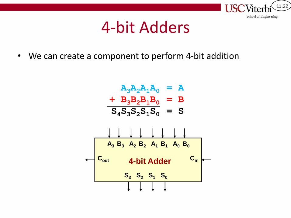
4-bit Adders
• We can create a component to perform 4-bit addition
A3A2A1A0+ B3B2B1B0S4S3S2S1S0
= A
= B
= S
A3 B3 A2 B2 A1 B1 A0 B0
CinCout
S3 S2 S1 S0
4-bit Adder
11.23
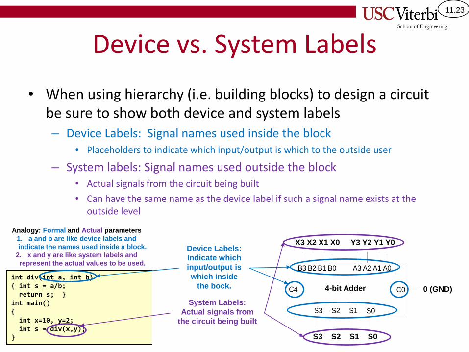
Device vs. System Labels
• When using hierarchy (i.e. building blocks) to design a circuit be sure to show both device and system labels– Device Labels: Signal names used inside the block
• Placeholders to indicate which input/output is which to the outside user
– System labels: Signal names used outside the block• Actual signals from the circuit being built
• Can have the same name as the device label if such a signal name exists at the outside level
B3 B2 B1 B0 A3 A2 A1 A0
S0S1S2S3
C0C4
Device Labels:
Indicate which
input/output is
which inside
the bock.
X3 X2 X1 X0 Y3 Y2 Y1 Y0
System Labels:
Actual signals from
the circuit being built
S3 S2 S1 S0
0 (GND)4-bit Adder
int div(int a, int b){ int s = a/b;return s; }
int main(){int x=10, y=2;int s = div(x,y);
}
Analogy: Formal and Actual parameters
1. a and b are like device labels and
indicate the names used inside a block.
2. x and y are like system labels and
represent the actual values to be used.

11.24
EXERCISES
11.25
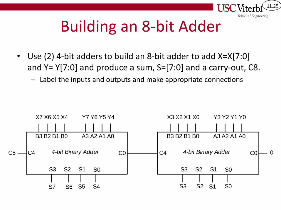
Building an 8-bit Adder
• Use (2) 4-bit adders to build an 8-bit adder to add X=X[7:0] and Y= Y[7:0] and produce a sum, S=[7:0] and a carry-out, C8.– Label the inputs and outputs and make appropriate connections
B3 B2 B1 B0 A3 A2 A1 A0
S0S1S2S3
C0C4 4-bit Binary Adder
B3 B2 B1 B0 A3 A2 A1 A0
S0S1S2S3
C0C4 4-bit Binary Adder
X3 X2 X1 X0 Y3 Y2 Y1 Y0X7 X6 X5 X4 Y7 Y6 Y5 Y4
S3 S2 S1 S0S7 S6 S5 S4
0C8
11.26
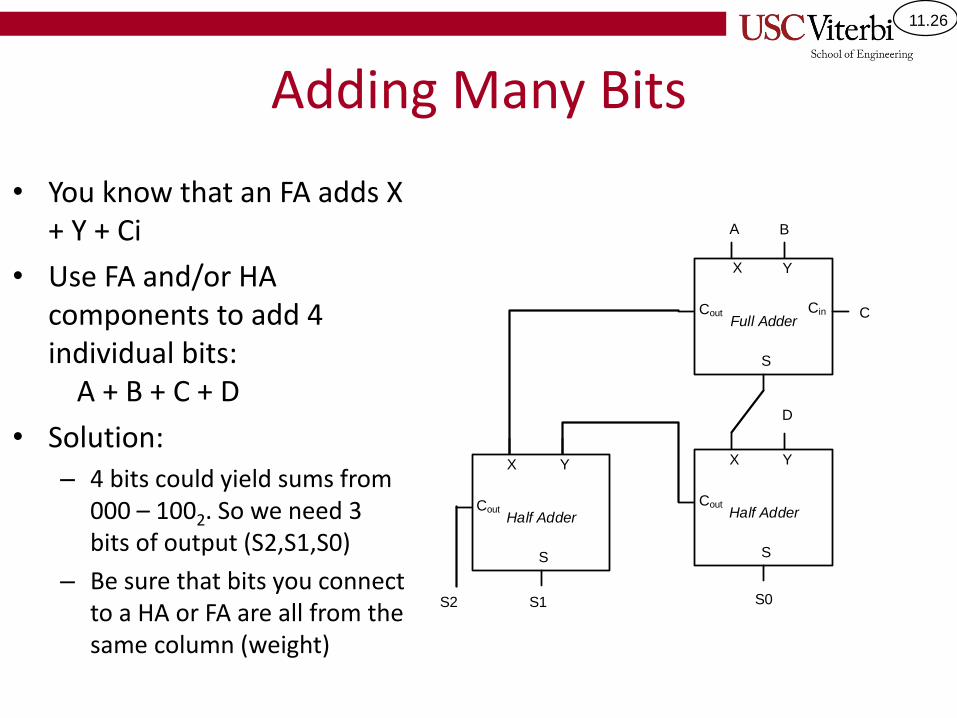
Adding Many Bits
• You know that an FA adds X + Y + Ci
• Use FA and/or HA components to add 4 individual bits:
A + B + C + D
• Solution:– 4 bits could yield sums from
000 – 1002. So we need 3 bits of output (S2,S1,S0)
– Be sure that bits you connect to a HA or FA are all from the same column (weight)
X Y
S
Cin
Full AdderCout
X Y
S
Half AdderCout
X Y
S
Half AdderCout
A B
C
D
S2 S1 S0
11.27
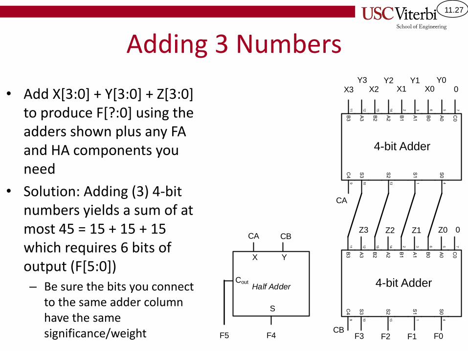
Adding 3 Numbers
• Add X[3:0] + Y[3:0] + Z[3:0] to produce F[?:0] using the adders shown plus any FA and HA components you need
• Solution: Adding (3) 4-bit numbers yields a sum of at most 45 = 15 + 15 + 15 which requires 6 bits of output (F[5:0])– Be sure the bits you connect
to the same adder column have the same significance/weight
X3 X2 X1 X0Y3 Y2 Y1 Y0
0
CA
Z3 Z2 Z1 Z0 0
F3 F2 F1 F0CB
X Y
S
Half AdderCout
CBCA
F4F5
4-bit Adder
4-bit Adder
11.28
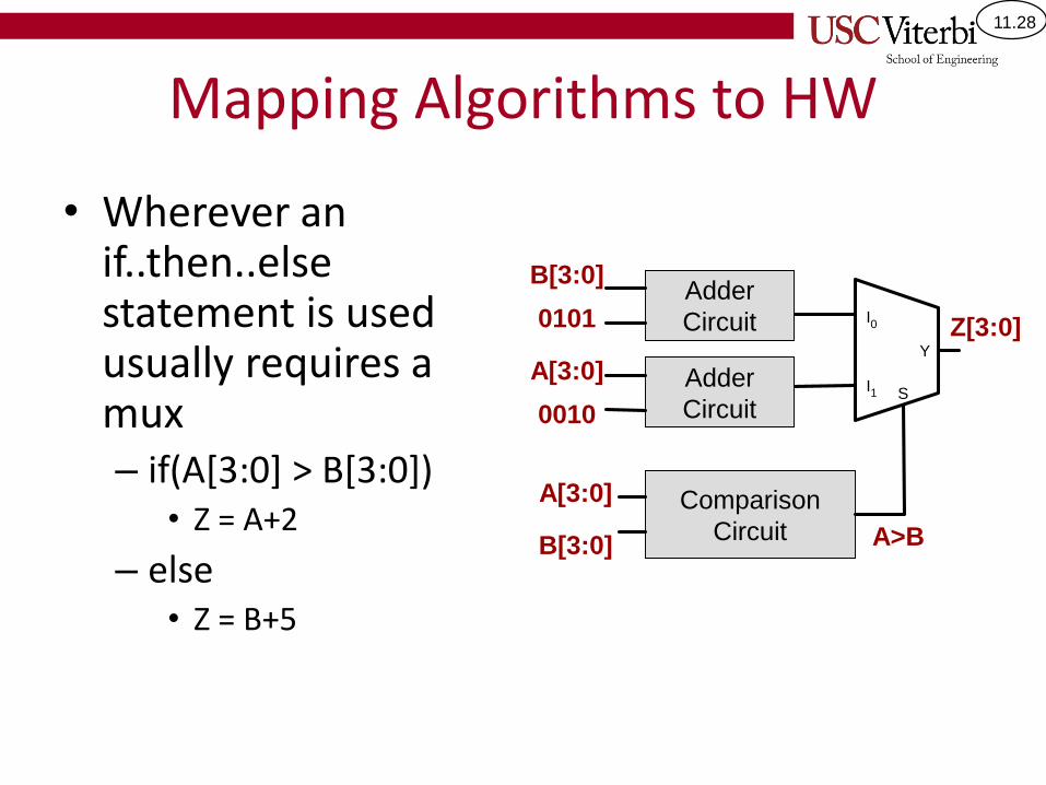
Mapping Algorithms to HW
• Wherever an if..then..else statement is used usually requires a mux– if(A[3:0] > B[3:0])
• Z = A+2
– else• Z = B+5
I1
Y
S
I0
Comparison
CircuitB[3:0]
A[3:0]
A>B
B[3:0]
Z[3:0]
Adder
Circuit
A[3:0] Adder
Circuit
0101
0010
11.29
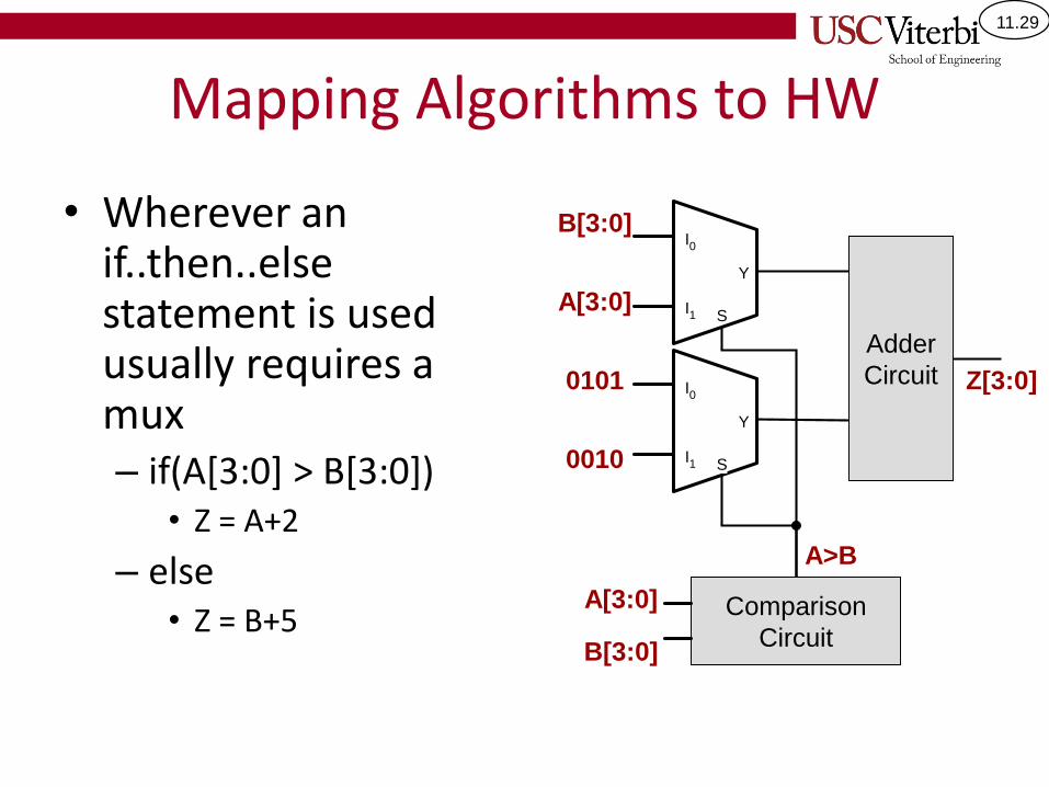
Mapping Algorithms to HW
• Wherever an if..then..else statement is used usually requires a mux– if(A[3:0] > B[3:0])
• Z = A+2
– else• Z = B+5 Comparison
CircuitB[3:0]
A[3:0]
A>B
B[3:0]
Z[3:0]
Adder
Circuit
A[3:0]
0101
0010
I1
Y
S
I0
I1
Y
S
I0
11.30
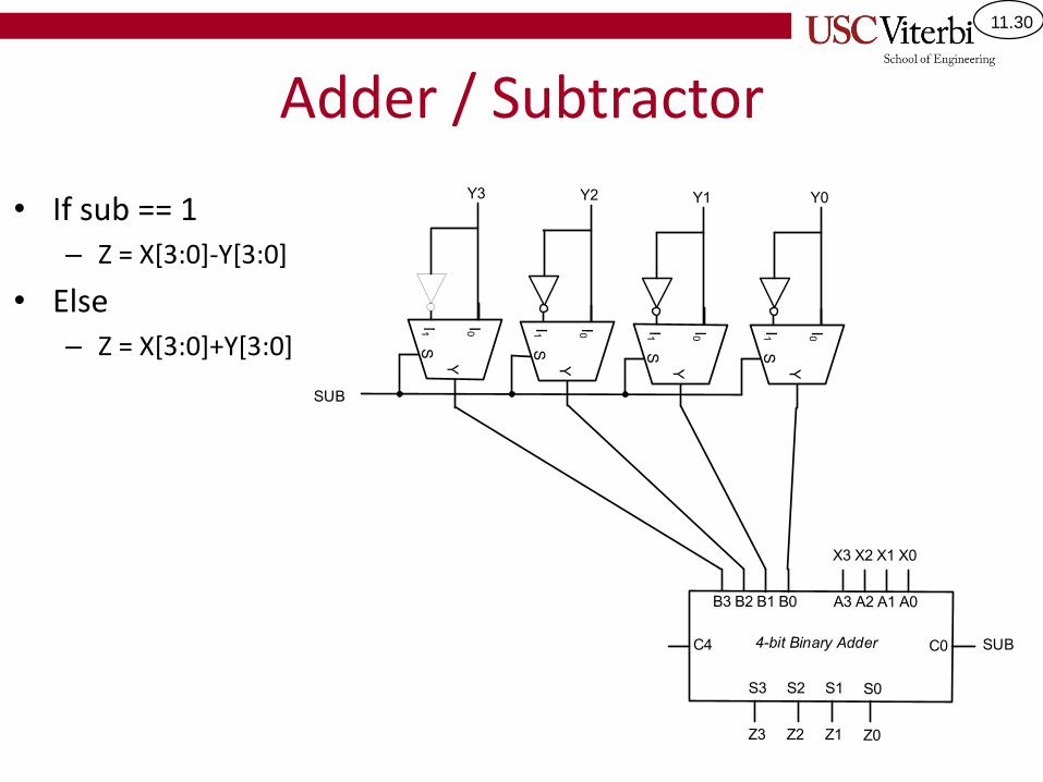
Adder / Subtractor
• If sub == 1– Z = X[3:0]-Y[3:0]
• Else– Z = X[3:0]+Y[3:0]
11.31
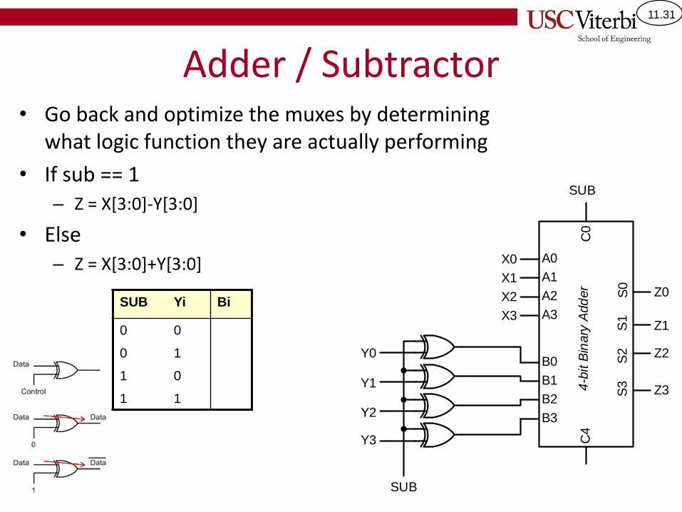
Adder / Subtractor• Go back and optimize the muxes by determining
what logic function they are actually performing
• If sub == 1– Z = X[3:0]-Y[3:0]
• Else– Z = X[3:0]+Y[3:0]
SUB Yi Bi
0 0
0 1
1 0
1 1
B3
B2
B1
B0
A3
A2
A1
A0
S0
S1
S2
S3
C0
C4
4-b
it B
inary
Add
er
X3
X2
X1
X0
Y3
Y2
Y1
Y0
SUB
Z3
Z2
Z1
Z0
SUB
11.32
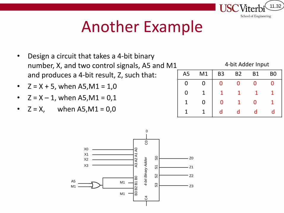
Another Example
• Design a circuit that takes a 4-bit binary number, X, and two control signals, A5 and M1 and produces a 4-bit result, Z, such that:
• Z = X + 5, when A5,M1 = 1,0
• Z = X – 1, when A5,M1 = 0,1
• Z = X, when A5,M1 = 0,0
4-bit Adder Input
A5 M1 B3 B2 B1 B0
0 0 0 0 0 0
0 1 1 1 1 1
1 0 0 1 0 1
1 1 d d d d
X3
X2
X1
X0
B3
B2
B1
B0
A3
A2
A1
A0
S0
S1
S2
S3
C0
C4
4-b
it B
inary
Add
er
A5
M1 Z3
Z2
Z1
Z0
M1
M1
0