Embed Size (px)
Citation preview
Document Number: EDS 08-5021
Version: 1.0
Date: 27/02/2017
TH
IS IS
AN
UN
CO
NT
RO
LL
ED
DO
CU
ME
NT
, T
HE
RE
AD
ER
MU
ST
CO
NF
IRM
IT
S V
AL
IDIT
Y B
EF
OR
E U
SE
ENGINEERING DESIGN STANDARD
EDS 08-5021
TIMED CONNECTIONS
Network(s): EPN, LPN, SPN
Summary: This standard provides guidance on the application of timed connections.
Author: Ali Reza Ahmadi Date: 27/02/2017
Approver: Barry Hatton Date: 12/05/2017
This document forms part of the Company’s Integrated Business System and its requirements are mandatory throughout UK Power Networks. Departure from these requirements may only be taken with the written approval of the Director of Asset Management. If you have any queries about this document please contact the author or owner of the current issue.
Applicable To
UK Power Networks External
☒ Asset Management ☒ G81 Website
☐ Capital Programme ☒ UK Power Networks Services
☐ Connections ☐ Contractors
☐ Health & Safety ☒ ICPs/IDNOs
☐ Legal ☐ Meter Operators
☐ Network Operations
☐ Procurement
☐ Strategy & Regulation
☐ Technical Training

Timed Connections Document Number: EDS 08-5021
Version: 1.0
Date: 27/02/2017
© UK Power Networks 2017 All rights reserved 2 of 20
Revision Record
Version 1.0 Review Date 12/05/2018
Date 27/02/2017 Author Ali Reza Ahmadi
New document facilitating Timed Connections as an alternative connection for load and generation across LPN, SPN and EPN.
Timed Connections Document Number: EDS 08-5021
Version: 1.0
Date: 27/02/2017
© UK Power Networks 2017 All rights reserved 3 of 20
Contents
1 Introduction ............................................................................................................. 5
2 Scope ....................................................................................................................... 5
3 Glossary and Abbreviations ................................................................................... 5
4 Timed Connections Overview ................................................................................. 6
4.1 Connection Offer with the Uncontrolled I/O Profile ..................................................... 7
4.2 Connection Offer with the Controlled I/O Profile ........................................................ 7
5 Assessment for new Connections ......................................................................... 7
5.1 Timed Connection Logic ............................................................................................ 9
5.2 Description of Logic ................................................................................................. 11
5.3 Equipment ............................................................................................................... 15
5.4 Commissioning ........................................................................................................ 15
5.5 Roles and Responsibilities ....................................................................................... 15
5.5.1 Connections ............................................................................................................ 15
5.5.2 Asset Management.................................................................................................. 15
5.5.3 Procurement ............................................................................................................ 16
5.5.4 Network Operations and Capital Programme........................................................... 16
5.5.5 Income Management ............................................................................................... 16
5.5.6 Safety, Strategy and Support Services .................................................................... 16
6 Records .................................................................................................................. 16
7 References ............................................................................................................. 17
7.1 UK Power Networks Standards ............................................................................... 17
7.2 National Standards .................................................................................................. 17
Appendix A – Timed Connection Logic Wizard .............................................................. 18
Appendix B – Timed Connection Assessment Tool ....................................................... 19
Appendix C – Timed Connection Requirement Specification ........................................ 20
Figures
Figure 5-1 – Timed Connection Application and Assessment Flow Chart.............................. 8
Figure 5-2 – Interface between UKPN and Customer’s Equipment. ...................................... 9
Figure 5-3 – Interface between UKPN and Customer’s Equipment via a dedicated CB. ...... 10
Figure 5-4 – Timed Connection Windows of Operation (Timed Logic Wizard) ..................... 11
Figure 5-5 – Customer Substation Monitoring and Control Logic ........................................ 13
Figure 5-6 – Timed Connection Sensing Logic .................................................................... 14
Figure 7-1 – Timed Connection Logic Wizard (Timers) ....................................................... 18

Timed Connections Document Number: EDS 08-5021
Version: 1.0
Date: 27/02/2017
© UK Power Networks 2017 All rights reserved 4 of 20
Tables
Table 5-1 – Timed Connection Example for a Load .............................................................. 9
Timed Connections Document Number: EDS 08-5021
Version: 1.0
Date: 27/02/2017
© UK Power Networks 2017 All rights reserved 5 of 20
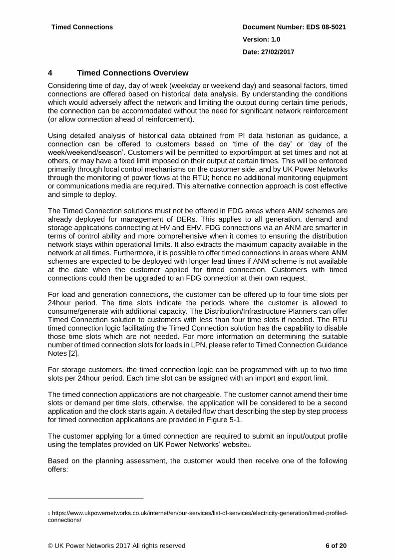
1 Introduction
This document provides recommendations for the application of Timed Connection Logic (TCL) to customer connections. Timed connections have been highlighted as a key network solution in the development of Smart Grids and covers a broad range of technologies, scales and operating models for load, generation and storage.
The purpose of this document is to:
Provide sufficient background and guidance to assist customers with their application requests for a timed connection.
Propose “good connection practices” for applications in order to guarantee compliance with License Conditions and relevant Engineering Recommendations.
Provide guidance for commercial and technical staff on the use and application of TCL.
2 Scope
This document details the standard applied in the assessment of time constrained connections for load, generation and storage across all networks that form part of UK Power Networks. It details the functionality and operation of these connections as well as the network considerations required prior to making an offer. It also details the approach for offering time constrained connection offers.
3 Glossary and Abbreviations
Term Definition
ANM Active Network Management
CB Circuit Breaker
DER Distributed Energy Resources
DNO Distribution Network Operator
DNV Distribution Network Visibility
EHV Extra High Voltage
FAT Factory Acceptance Testing
FDG Flexible Distributed Generation
GPRS General Packet Radio Service
HV High Voltage - The ESQCR Regulations 2002 (3) defines HV as 'any voltage exceeding LV (i.e. >1000V)'.
I/O Input/Output
PV Photovoltaic
QL Quote Lite
RTU Remote Telemetry Unit
SAT Site Acceptance Testing
UKPN UK Power Networks (Operations) Ltd consists of three electricity distribution networks:
Eastern Power Networks plc (EPN).
London Power Network plc (LPN).
South Eastern Power Networks plc (SPN).
Timed Connections Document Number: EDS 08-5021
Version: 1.0
Date: 27/02/2017
© UK Power Networks 2017 All rights reserved 6 of 20
4 Timed Connections Overview
Considering time of day, day of week (weekday or weekend day) and seasonal factors, timed connections are offered based on historical data analysis. By understanding the conditions which would adversely affect the network and limiting the output during certain time periods, the connection can be accommodated without the need for significant network reinforcement (or allow connection ahead of reinforcement).
Using detailed analysis of historical data obtained from PI data historian as guidance, a connection can be offered to customers based on ‘time of the day’ or ‘day of the week/weekend/season’. Customers will be permitted to export/import at set times and not at others, or may have a fixed limit imposed on their output at certain times. This will be enforced primarily through local control mechanisms on the customer side, and by UK Power Networks through the monitoring of power flows at the RTU; hence no additional monitoring equipment or communications media are required. This alternative connection approach is cost effective and simple to deploy.
The Timed Connection solutions must not be offered in FDG areas where ANM schemes are already deployed for management of DERs. This applies to all generation, demand and storage applications connecting at HV and EHV. FDG connections via an ANM are smarter in terms of control ability and more comprehensive when it comes to ensuring the distribution network stays within operational limits. It also extracts the maximum capacity available in the network at all times. Furthermore, it is possible to offer timed connections in areas where ANM schemes are expected to be deployed with longer lead times if ANM scheme is not available at the date when the customer applied for timed connection. Customers with timed connections could then be upgraded to an FDG connection at their own request.
For load and generation connections, the customer can be offered up to four time slots per 24hour period. The time slots indicate the periods where the customer is allowed to consume/generate with additional capacity. The Distribution/Infrastructure Planners can offer Timed Connection solution to customers with less than four time slots if needed. The RTU timed connection logic facilitating the Timed Connection solution has the capability to disable those time slots which are not needed. For more information on determining the suitable number of timed connection slots for loads in LPN, please refer to Timed Connection Guidance Notes [2].
For storage customers, the timed connection logic can be programmed with up to two time slots per 24hour period. Each time slot can be assigned with an import and export limit.
The timed connection applications are not chargeable. The customer cannot amend their time slots or demand per time slots, otherwise, the application will be considered to be a second application and the clock starts again. A detailed flow chart describing the step by step process for timed connection applications are provided in Figure 5-1.
The customer applying for a timed connection are required to submit an input/output profile using the templates provided on UK Power Networks’ website1.
Based on the planning assessment, the customer would then receive one of the following offers:
1 https://www.ukpowernetworks.co.uk/internet/en/our-services/list-of-services/electricity-generation/timed-profiled-connections/
Timed Connections Document Number: EDS 08-5021
Version: 1.0
Date: 27/02/2017
© UK Power Networks 2017 All rights reserved 7 of 20
4.1 Connection Offer with the Uncontrolled I/O Profile
This refers to those connection applications which are monitored but not controlled. The timed connection monitoring logic within the RTU will report customer’s behaviour to UKPN via e-mail notification. Furthermore, customer’s load/generation is logged in a suitable event buffer in the RTU where UKPN can remotely access the events. There will be no real-time control of the customer’s load/generation, but any infringements to the agreement would be logged and may be acted on retrospectively. The customer will need to ensure they remain within their profile or risk disconnection. This applies only for PV connections2.
4.2 Connection Offer with the Controlled I/O Profile
This refers to those connection applications which must be monitored and controlled. The customer shall provide a local control system3 to ensure that they remain within the prescribed windows of operation. The system must be tested, demonstrated and approved by Network Operations and Capital Programme before going live (please see section 5.5 for detailed description of roles are responsibilities). The system must not be such that it can be overruled by the customer without UK Power Networks’ knowledge. In other words, the Timed Connection Logic, Limits and override abilities are read only to customers. Only UK Power Networks has write ability to change the configuration of Timed Connection Logic.
The local UK Power Networks RTU will monitor the connection and in the event that constraints are breached send a single signal to the customer control system to reduce the import/export to the agreed level. If the customer control system does not comply, the relevant circuit breaker4 would then be opened to disconnect load/generation (as applicable). This applies to all load connections and non-PV generation.
It should be noted that the first line of control of import/export is on the customer side of the connection, the timed logic installed by UK Power Networks is meant as the second line of control of import and export in the event of a failure of the customers control scheme to constrain import/export.
5 Assessment for new Connections
Customer must indicate in the application form that they would like to request for a timed connection offer. The levels of demand and generation across the distribution network will vary differently both daily and seasonally. Hence by analysing the historical fluctuations and applying constraints within certain fixed periods, there may be a reduction in the level of upstream reinforcement required to facilitate new connections. Where significant upstream reinforcement is required, the relevant constraints will be identified and analysed to see if the constraint conditions occur within a restricted time period. If a timed connection is deemed viable the planner must analyse the windows of operation using the appropriate ‘Timed Connection Assessment Tool’ and DNV (see Appendix B). The planners will offer the customer the minimum scheme (i.e. least cost solution) for the capacity and time windows that have been requested by the customer.
The key steps for assessing timed connection applications are presented in Figure 5-1:
2 This type of offer would normally apply to a connection where the technology type lends itself to a specific profile. PV profile should always be recorded in the Connection Agreement. 3 In case of Waterloo Bus Garage, Build Your Dream (BYD) which is a world leader in the development and production of lithium iron-phosphate automotive batteries designed the control system. 4 This breaker on the customer’s side will be dedicated to the additional load or generation only and will not be expected to disconnect the entire site.

Timed Connections Document Number: EDS 08-5021
Version: 1.0
Date: 27/02/2017
© UK Power Networks 2017 All rights reserved 8 of 20
Figure 5-1 – Timed Connection Application and Assessment Flow Chart
Customer makes timed connection
application for new connection with
their desired timed connection profile
window
Gateway process application as usual
Does the offer include reinforcement and/or substantial connection
costs?
YES
Inform the customer that the reinforcement/substantial connection costs cannot be avoided for that part of the
network. Inform the customer that their application could be Treated as BAU if they instead desire a standard connection.
Also, include any additional works that might be required for this
conversion.
Connections design and price on basis
of Asset Management/
Distribution Planning design
Relevant Connections person
adds additional paragraph to Quote
Lite (QL)
Relevant Connections person
copies customer tables and sends with quotation to
customer
If project is accepted tables to be sent to Income Management for
inclusion in Connection Agreement
Connection Agreement MUST
be issued and signed by customer prior to energisation
Post connection/energisation monitoring process and
depository for information
TBA
Start
NO
Relevant connections team refers to planning
team for assessment
Connection Designer compares customer’s request
against the set criteria and suggests
conversion to a standard
connection application if the
criteria are not met.
YES
Treat as a BAU – Clocks to be restarted if Connections decide it will be treated as a Material
change
Does the customer accept converting the Timed Connection application to a
BAU?
NO
Planning feedbacks to Connections and Connections
communicate to the customer to either lower the MPR or to
change time windows - Clocks are paused
NO
Use proposed minimum scheme that was based on customer’s original timed connection
application
Planning proposes minimum scheme based on alternative time windows
and clocks are either resumed or restarted based on judgement call
made by Connections
NO
YES
Does the customer provide a lower MPR or a different
time window?
Does the customer accept the
alternative time windows to avoid reinforcement and/or
substantial connection costs?
YES
NO
Can the customer’s time windows be simply shifted to avoid reinforcement and/or
substantial connection costs?
Is the customer’s site located in an area where the
network is highly congested?
Planning proposes minimum scheme based on lower MPR or different
time window and clocks are either resumed or restarted based on
judgement call made by Connections
Clocks are resumed
YES
NO
Planning proposes the minimum
scheme based on the customer’s
timed connection application
YES
Clocks are resumed
Planning feedbacks to Connections and Connections
suggest to the customer alternative time windows -
Clocks are paused
Timed Connections Document Number: EDS 08-5021
Version: 1.0
Date: 27/02/2017
© UK Power Networks 2017 All rights reserved 9 of 20
If the minimum scheme that has been specified by planners does not include any reinforcement and/or substantial connection costs, Connections may issue a quote and wait for customer’s reply. The customer will be notified of their confirmed time and seasonal (and in some cases daily) limitations. Table 5-1 illustrates an example for windows of operation with two time slots for a load connection:
Table 5-1 – Timed Connection Example for a Load
Time period 1 2
From 23:30 06:31
To 06:30 23:29
New Load/Generation (Amps) 130 100
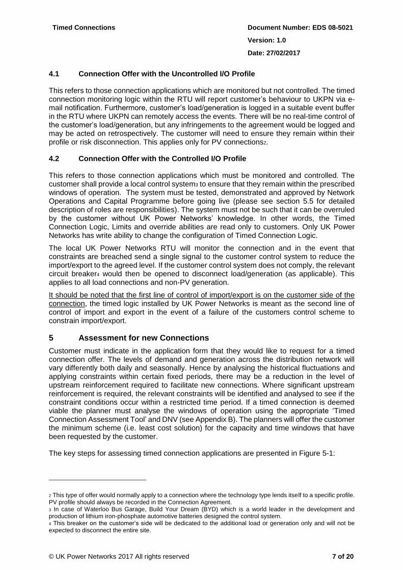
5.1 Timed Connection Logic
TCL is applied on the UK Power Networks’ RTU at the customer interface substation(s). This will become the standard for existing and new RTUs. The existing RTUs may need their software to be upgraded to be able to host the Timed Connection Logic. The following diagram (Figure 5-2) illustrates the connection arrangement between UK Power Networks and customer’s equipment.
Figure 5-2 – Interface between UKPN and Customer’s Equipment.
Timed Connections Document Number: EDS 08-5021
Version: 1.0
Date: 27/02/2017
© UK Power Networks 2017 All rights reserved 10 of 20
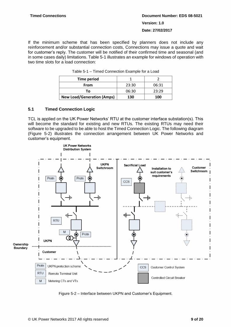
In addition, the following diagram (Figure 5-3) illustrates a dedicated metering circuit breaker on UKPN’s side directly interfacing with the customer’s circuit breaker where the sacrificial load is located:
Figure 5-3 – Interface between UKPN and Customer’s Equipment via a dedicated CB.
Timed Connections Document Number: EDS 08-5021
Version: 1.0
Date: 27/02/2017
© UK Power Networks 2017 All rights reserved 11 of 20
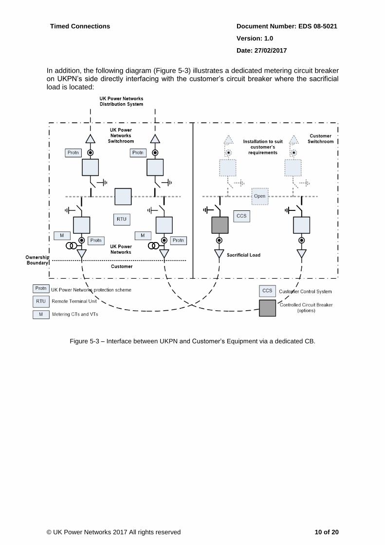
Figure 5-4 outlines the list of inputs for the TCL wizard. The TCL has up to 4 configurable time slots per day (these time slots have an enable/disable check box). The time slots are configurable for Weekdays and Weekends based on two seasons (Summer and Winter) with 16 total different time frames and thresholds per year.
Timer for Trigger (S) 0-3600 Sec
Timer for Bad I/O (S) 0-3600 Sec
Timer Settings
All timers will have a pre set values that can be overwritten
Enable LogicCheck box to enable logic. If not
checked settings below hidden, if checked settings available
PLEASE NOTE, +ve MW VALUE IS EXPORT (GENERATION), -ve MW VALUE IS IMPORT (LOAD)
Summer Settings
Start Date 01/04Pre set value that can be
overwritten
Weekdays
Start Time
End Time
Value (A)
Winter Settings
Start Date 01/10Pre set value that can be
overwritten
Weekdays
Weekends Weekends
Check box to enable/disable settings
Timed Connection Logic Wizard
Power Flow Direction
Start Time
End Time
Value (A)
Power Flow Direction
Start Time
End Time
Value (A)
Power Flow Direction
Start Time
End Time
Value (A)
Power Flow Direction
Check box to enable/disable settings
Check box to enable/disable settings Check box to enable/disable settings
Power Flow Direction drop down menu (+ve/-ve)
Enabled drop down menu (y/n)
Enabled
Power Flow Direction drop down menu (+ve/-ve)
Enabled drop down menu (y/n)
Enabled
EnabledEnabled
Figure 5-4 – Timed Connection Windows of Operation (Timed Logic Wizard)
5.2 Description of Logic
The configurable ‘trigger’ set-points per time slots are given in Amps. The time windows blocks will be synchronised in order to account for changes between summer and winter times. The power flow monitoring blocks for each time window are configured with a static limit and are fed by a suitable analogue monitoring device, installed at the metering breaker, capable of providing directional power monitoring (W, Amps). The logic must take account of the direction of power flow and the current value (A).
Where the current value exceeds the limit corresponding to the current time window for a configurable amount of time, with the power flow in the prescribed direction, an alarm is sent to Power-On and to the customer control system (please see Figure 5-4). If no action is taken within a set time set by the UK Power Networks planning engineer, the logic initiates the turn down/off process for the customer’s demand/generation (this option must be able to be enabled/disabled within the logic as required). To keep consistency with the ANM failsafe timers, a value of 10mins (i.e. 600seconds) is proposed as the default for trip signal timer. However, the process may also be initiated when the RTU detects ‘bad’ I/O. In that case the control engineer will get the relevant alarm. The control engineer must have the option to enable or disable the whole logic function as required from Power-On.
Timed Connections Document Number: EDS 08-5021
Version: 1.0
Date: 27/02/2017
© UK Power Networks 2017 All rights reserved 12 of 20
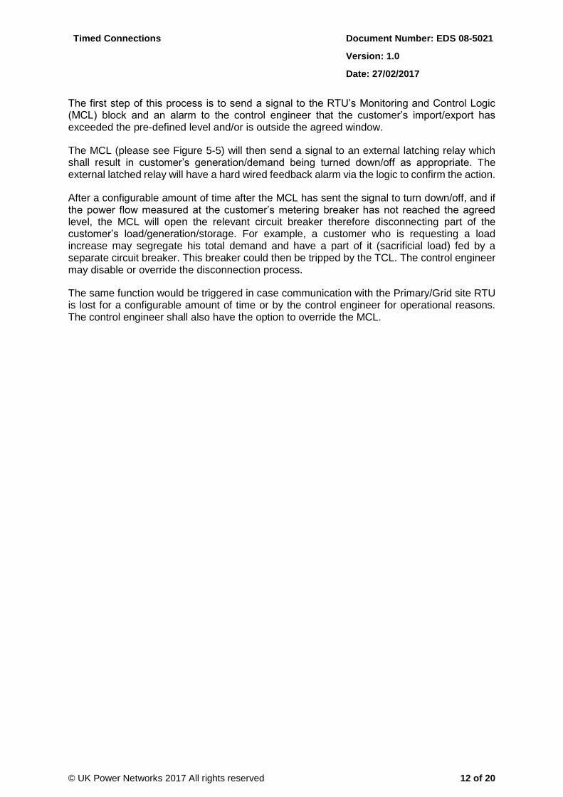
The first step of this process is to send a signal to the RTU’s Monitoring and Control Logic (MCL) block and an alarm to the control engineer that the customer’s import/export has exceeded the pre-defined level and/or is outside the agreed window.
The MCL (please see Figure 5-5) will then send a signal to an external latching relay which shall result in customer’s generation/demand being turned down/off as appropriate. The external latched relay will have a hard wired feedback alarm via the logic to confirm the action.
After a configurable amount of time after the MCL has sent the signal to turn down/off, and if the power flow measured at the customer’s metering breaker has not reached the agreed level, the MCL will open the relevant circuit breaker therefore disconnecting part of the customer’s load/generation/storage. For example, a customer who is requesting a load increase may segregate his total demand and have a part of it (sacrificial load) fed by a separate circuit breaker. This breaker could then be tripped by the TCL. The control engineer may disable or override the disconnection process.
The same function would be triggered in case communication with the Primary/Grid site RTU is lost for a configurable amount of time or by the control engineer for operational reasons. The control engineer shall also have the option to override the MCL.
Timed Connections Document Number: EDS 08-5021
Version: 1.0
Date: 27/02/2017
© UK Power Networks 2017 All rights reserved 13 of 20
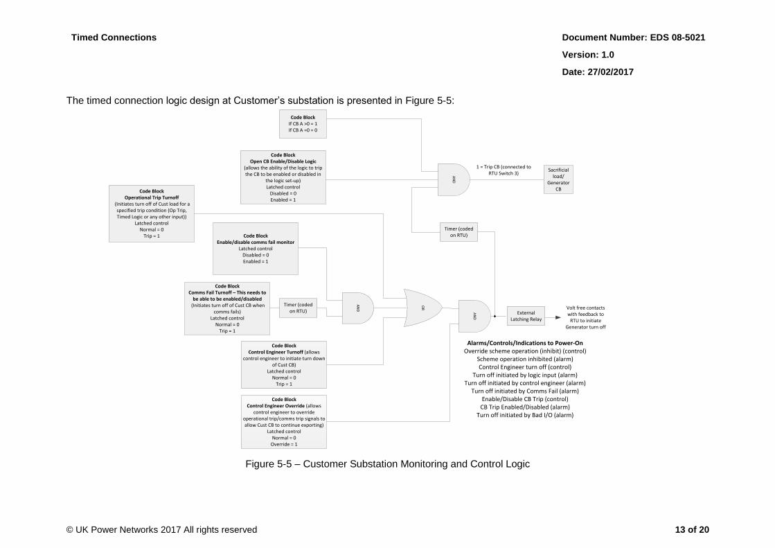
The timed connection logic design at Customer’s substation is presented in Figure 5-5:
Figure 5-5 – Customer Substation Monitoring and Control Logic
OR
AN
D
External Latching Relay
Timer (coded on RTU)
AN
D
Sacrificial load/
Generator CB
Code BlockControl Engineer Override (allows
control engineer to override operational trip/comms trip signals to allow Cust CB to continue exporting)
Latched controlNormal = 0
Override = 1
Code BlockControl Engineer Turnoff (allows
control engineer to initiate turn down of Cust CB)
Latched controlNormal = 0
Trip = 1
Code BlockComms Fail Turnoff – This needs to
be able to be enabled/disabled (Initiates turn off of Cust CB when
comms fails)Latched control
Normal = 0Trip = 1
Timer (coded on RTU)
Volt free contacts with feedback to
RTU to initiate Generator turn off
1 = Trip CB (connected to RTU Switch 3)
Code BlockOpen CB Enable/Disable Logic
(allows the ability of the logic to trip the CB to be enabled or disabled in
the logic set-up)Latched control
Disabled = 0Enabled = 1
Code BlockIf CB A >0 = 1If CB A =0 = 0
Code BlockOperational Trip Turnoff
(Initiates turn off of Cust load for a specified trip condition (Op Trip, Timed Logic or any other input))
Latched controlNormal = 0
Trip = 1
Alarms/Controls/Indications to Power-OnOverride scheme operation (inhibit) (control)
Scheme operation inhibited (alarm)Control Engineer turn off (control)
Turn off initiated by logic input (alarm)Turn off initiated by control engineer (alarm)
Turn off initiated by Comms Fail (alarm)Enable/Disable CB Trip (control)
CB Trip Enabled/Disabled (alarm)Turn off initiated by Bad I/O (alarm)
Code BlockEnable/disable comms fail monitor
Latched controlDisabled = 0Enabled = 1
AN
D

Timed Connections Document Number: EDS 08-5021
Version: 1.0
Date: 27/02/2017
© UK Power Networks 2017 All rights reserved 14 of 20
The Timed Connection Sensing Logic to be design for UK Power Networks RTU is demonstrated in Figure 5-6:
Figure 5-6 – Timed Connection Sensing Logic
AN
D
Code BlockControl Engineer Enable/Disable
Logic (allows control engineer disable scheme and take remote control of
initiation of turn down of gen)Latched control
Disabled = 0Enabled = 1
Alarm to control engineer to say customer operating
outside of agreed window and control to signal
Operational Tripping logic to operate
Code BlockBad I/O Turnoff
(Initiates turn off of gen if any I/O is bad)
Latched controlNormal = 0
Trip = 1
Timer (coded in RTU)
Alarm to control engineer to say gen trip initiated by Bad
I/0
Need to have 3 date/time options for different time periods:
WeekdayWeekend
Summer/Winter
OR
Code BlockRTU Clock
(Initiates turn off of gen when constraint dates’ met)
Latched controlNormal = 0
Trip = 1
Code BlockW Monitor
Set up wizard to set trigger for +ve (load) or -ve (generation) or +ve
(storage) power flowLatched control
Direction not triggered = 0Direction triggered = 1
Timer (coded in RTU)
AN
D
Code BlockA Monitor
(Initiates turn off alarm and trip of gen for a specified trip condition)
Latched controlNormal = 0
Meter CB A=>(+/-) x = 1
Alarms/Controls/Indication to Power-OnInhibit scheme operation (control)Scheme inhibited (alarm)Customer operating outside of agreement (alarm)Turn Off Initiated by Bad I/O (alarm)RTU Clock invalid
Code BlockRTU Date/Time Validation (RTU must
check the date/time is valid)Latched control
Invalid = 0Valid = 1
x16, one for each time slot
Timed Connections Document Number: EDS 08-5021
Version: 1.0
Date: 27/02/2017
© UK Power Networks 2017 All rights reserved 15 of 20
5.3 Equipment
In addition to the standard equipment required for a typical connection, for new or existing connections, the following equipment will also be required:
UK Power Networks RTU (i.e. Lucy, Remsdaq or GE) installed/upgraded with Timed Connection Logic.
The customer will require suitable control system for turning down/up demand/generation. This shall meet the interface/compatibility requirements defined by UK Power Networks.
The customer will require their own circuit breaker for providing the means to disconnect the additional load/generation capacity provided by the timed connection and design their installation accordingly.
Communication Medium: this can be hardwired, satellite, radio or GPRS and will depend on the level of security required by the customer. The TCL has a configurable time delay to wait before it initiates any turn down/off command to the customer to cope with any minor breaks in communication associated with wireless communication.
5.4 Commissioning
The commissioning consists of FAT and SAT on UK Power Networks’ RTU which is programmed with customer’s timed connection profile. The details of these tests will be provided by the RTU vendors which are based on UKPN’s timed connection requirement specification (refer to Appendix C).
A dedicated RTU Commissioning Wizard accessed via a dedicated password is designed by Lucy and Remsdaq which will be used by the commissioning engineer to commission the RTU.
5.5 Roles and Responsibilities
5.5.1 Connections
The connections team is responsible for collecting the customer’s application details and providing them to Asset Management (Infrastructure Planning) or Network Operations (Distribution Planning) for assessment. Connections teams are responsible for ensuring that the requirements of this standard are considered in scheme design and when allocating costs to customer offers. In addition, connections are responsible for storing and maintaining the relevant commercial information on CRM, Alfresco folder structure and pass this information to Income Management (for production of Connection Agreements).
5.5.2 Asset Management
This department is responsible for reviewing current and future network requirements to inform and develop the necessary business capabilities to deliver and be ready to meet new service requirements. It is the responsibility of Asset Management (with input from Network Operations (Distribution Planning, Control/Control Systems and Automation)) to specify the minimum system monitoring requirements and granularity of the data collected. Asset Management are responsible for providing Network Operations (Operational Telecommunications) with the network monitoring requirements.
Timed Connections Document Number: EDS 08-5021
Version: 1.0
Date: 27/02/2017
© UK Power Networks 2017 All rights reserved 16 of 20
The infrastructure/distribution planning engineers are responsible for the identification of network constraints for the new load/generation connections. The planner will assess the reinforcement required for the connection of the load or generation requested by the customer within the time slots specified by the customer with the help of Timed Connection Assessment Tool [1] and any other tool. The planners are also able to use the tool to perform curtailment assessment based on timed connections where generators have their output restricted at predetermined times.
5.5.3 Procurement
Procurement will be responsible for the purchase of the equipment solutions in accordance with this standard and should ensure that all the necessary framework agreements are in place to facilitate the business needs and technical requirements as defined.
5.5.4 Network Operations and Capital Programme
Network Operations and Capital Programme are jointly responsible for identifying best practices for implementation to ensure that timed connection design and fail-safe requirements are achieved. The control room engineer has override ability on Timed Connection Logic to manually or automatically disconnect additional load/generation. Capital Programme are responsible for ensuring customer connections adhere to this policy. Network Operations (Operational Telecommunications) are responsible for defining the available granularity, accuracy and latency of analogue data based on the network equipment (CTs, transducers, IEDs etc.) involved in the collection of the data. Network Operation must ensure that windows of timed connection operation are recorded with information pins on SCADA HMI.
5.5.5 Income Management
Income Management will be responsible for issuing the Connection Agreement and ensuring that the agreed operational profile is accurately represented and agreed with the customer.
5.5.6 Safety, Strategy and Support Services
Safety, Strategy and Support Services teams are responsible for ensuring that the installations meet the required standards.
6 Records
Individual items of network equipment shall be recorded in the asset register against the relevant substation, and basic information (nameplate data) such as manufacturer, type, serial number, software version shall be held against the asset.
If an asset is removed, the network information will be recorded detailing why it was removed.
Information in relation to windows of operations and site specific requirements should be maintained as a minimum in SAP CRM, Power-On and recorded in the customer’s Connection Agreement.
In addition, all data related to Timed Connection will need to be recorded in MAVIS either in the notes section or once it is updated in the designated data boxes for time windows and MPRs (Maximum Power Requirements). As this is a long-term solution, an intermediate solution needs to be specified so data is not lost, is recorded properly and can later be transferred to MAVIS (or any other specified data platform) simply and error free.
Timed Connections Document Number: EDS 08-5021
Version: 1.0
Date: 27/02/2017
© UK Power Networks 2017 All rights reserved 17 of 20
Therefore, it is suggested that Distribution/Infrastructure Planning upgrades Access database that it currently uses to include a tickbox that will be ticked when a Timed Connection is entered in the database as well as two (or four depending on the number of time connection slots) fields that will be used to enter the time windows and two (or four depending on the number of time connection slots) fields that will be used to enter the corresponding capacity per time window.
7 References
[1] Timed Connection Assessment Tool. Provided to Lead Planners in EPN (Jose Barros), LPN (Chris Knightly) and SPN (Zivanayi Musanhi)
Location: Bexdat01 > Work > Power Networks > Asset Management > Major Projects > Legacy Data > Network Management > Planning > Distribution > Veronique
[2] LPN Distribution Planning, ‘Timed Connection Guidance Notes for Loads’.
Location: Bexdat01 > Work > Power Networks > Asset Management > Major Projects > Legacy Data > Network Management > Planning > Distribution > Veronique
7.1 UK Power Networks Standards
EOS 04-1020 Transformer Ratings
EDS 08-1901 Guidance for the Connection of Customers Disturbing Loads
7.2 National Standards
ESQCR 2002 Electricity Safety, Quality and Continuity Regulations 2002.
ENA EREC P2/6 Engineering Recommendation P2/6 Security of Supply.
ENA EREC G5/4 Engineering Recommendation Harmonic Voltage Distortion.
ENA EREC P17 Engineering Recommendation Planning Levels for Harmonic Voltage Distortion and the Connection of Non-Linear Equipment to Transmission Systems and Distribution Networks.
ENA EREC P18 Engineering Recommendation Complexity of 132kV Circuits.
ENA EREC P27 Engineering Recommendation Current Rating Guide for High Voltage Overhead Lines Operating in the UK Distribution System.
ENA EREC P28 Engineering Recommendation for Planning limits for voltage fluctuations caused by industrial, commercial and domestic equipment.
ENA EREC G59 Engineering Recommendation for the Connection of Generating Plant to the Distribution Systems of Licensed Distribution Network Operators.
ENA EREC G83 Engineering Recommendations for the Connection of Type Tested Small-scale Embedded Generators (Up to 16A per Phase) in Parallel with Low-Voltage Distribution Systems.
ENA EREC G100 Engineering Recommendations Technical Requirements for Customer Export Limiting Schemes.
Timed Connections Document Number: EDS 08-5021
Version: 1.0
Date: 27/02/2017
© UK Power Networks 2017 All rights reserved 18 of 20
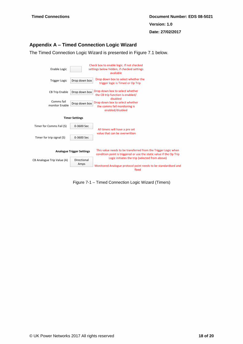
Appendix A – Timed Connection Logic Wizard
The Timed Connection Logic Wizard is presented in Figure 7.1 below.
Timer for Comms Fail (S) 0-3600 Sec
0-3600 SecTimer for trip signal (S)
CB Analogue Trip Value (A)
Analogue Trigger Settings
Directional Amps
Timer Settings
All timers will have a pre set value that can be overwritten
This value needs to be transferred from the Trigger Logic when condition point is triggered or use the static value if the Op Trip
Logic initiates the trip (selected from above)
Monitored Analogue protocol point needs to be standardised and fixed
Enable LogicCheck box to enable logic. If not checked settings below hidden, if checked settings
available
Drop down boxTrigger Logic Drop down box to select whether the trigger logic is Timed or Op Trip
Drop down boxCB Trip Enable Drop down box to select whether the CB trip function is enabled/
disabled
Drop down boxComms fail
monitor EnableDrop down box to select whether
the comms fail monitoring is enabled/disabled
Figure 7-1 – Timed Connection Logic Wizard (Timers)

Timed Connections Document Number: EDS 08-5021
Version: 1.0
Date: 27/02/2017
© UK Power Networks 2017 All rights reserved 19 of 20
Appendix B – Timed Connection Assessment Tool
Timed Connection Assessment Tool for Loads:
The Timed Connection assessment tool developed in Excel for load, identifies the times where loads have their profile restricted at predetermined times. It helps planners assess referrals under Firm and N-1 (i.e. Feeder Outage).
In addition, a dedicated Excel tool called ‘PI Data Peak Identification’ has been developed by Smart Grid Development team which can assist Distribution Planning Engineers with importing time series data from Excel PI Interface and identify the total weekly peak demands as well as weekly peak demands for individual feeders. The time & date of the weekly peak demands are calculated between a start and end time defined by timed connection window. Using the ‘PI Data Peak Identification’ tool, Distribution Planning Engineers are able to identify the representative peak demands between timed connection windows and perform a snapshot P2/6 connection referral study.
Timed Connection Assessment Tool for Generation:
The Timed Connection assessment tool for generation assesses the power to restrict export in non-solar hours (if we need to) should in the future the customer wishes to install other generation/energy storage behind the meter. It is likely to be suitable for generation (and energy storage) applying in solar-dominated areas, wishing to export outside solar times. It can also be suitable for combinations of generation ‘behind the meter’ exporting outside times of constraint. This tool is expected to help EPN and SPN planners manage network capacity more efficiently. As an example, the tool gives planners power to revise customer power requirements on a regular basis, in order to retrieve unused capacity. It will also give planners more confidence to offer capacity that is available ‘in the gaps’.
Timed Connections Document Number: EDS 08-5021
Version: 1.0
Date: 27/02/2017
© UK Power Networks 2017 All rights reserved 20 of 20
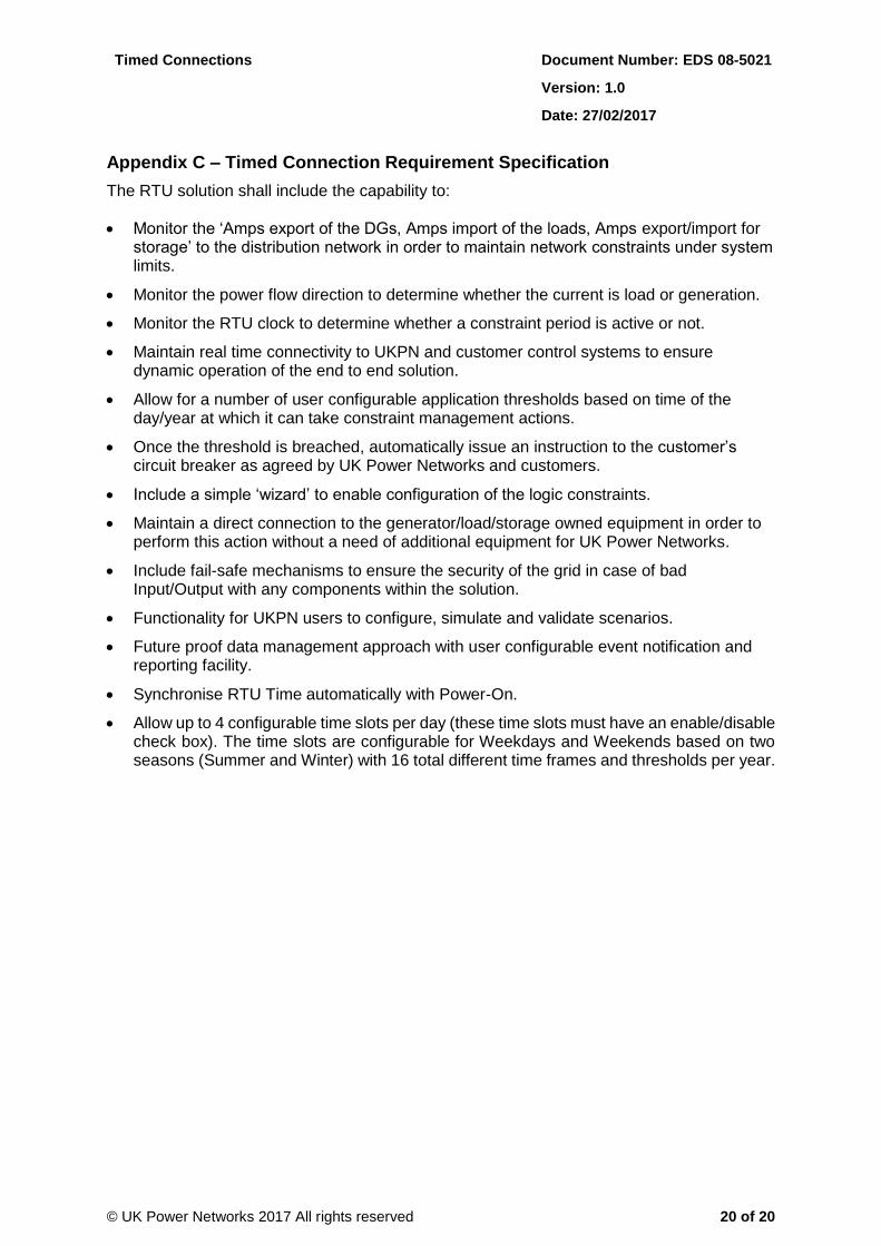
Appendix C – Timed Connection Requirement Specification
The RTU solution shall include the capability to:
Monitor the ‘Amps export of the DGs, Amps import of the loads, Amps export/import for storage’ to the distribution network in order to maintain network constraints under system limits.
Monitor the power flow direction to determine whether the current is load or generation.
Monitor the RTU clock to determine whether a constraint period is active or not.
Maintain real time connectivity to UKPN and customer control systems to ensure dynamic operation of the end to end solution.
Allow for a number of user configurable application thresholds based on time of the day/year at which it can take constraint management actions.
Once the threshold is breached, automatically issue an instruction to the customer’s circuit breaker as agreed by UK Power Networks and customers.
Include a simple ‘wizard’ to enable configuration of the logic constraints.
Maintain a direct connection to the generator/load/storage owned equipment in order to perform this action without a need of additional equipment for UK Power Networks.
Include fail-safe mechanisms to ensure the security of the grid in case of bad Input/Output with any components within the solution.
Functionality for UKPN users to configure, simulate and validate scenarios.
Future proof data management approach with user configurable event notification and reporting facility.
Synchronise RTU Time automatically with Power-On.
Allow up to 4 configurable time slots per day (these time slots must have an enable/disable check box). The time slots are configurable for Weekdays and Weekends based on two seasons (Summer and Winter) with 16 total different time frames and thresholds per year.