Embed Size (px)
Citation preview
Electrochemical Micro-machining: Review of Factors Affecting the Process
Applicability in Micro-Manufacturing
Rebecca Leese1, Dr Atanas Ivanov
Brunel University – School of Engineering & Design, Advanced Manufacturing and
Enterprise Engineering
1 [email protected] , Brunel University, Kingston Lane, Uxbridge,
Middlesex, UB8 3PH
Abstract
Electrochemical machining is a non-conventional machining technique used across a
large range of industries from aero to medical. A large number of papers exist on the
topic of electrochemical machining (ECM) and electrochemical micromachining
(ECMM) which is a daunting task to evaluate for anyone new to the subject. This paper
aims to summarise some of the major parameters used in electrochemical machining
which affect machining accuracy, machining rate and the suitability of the process for
micromachining. This paper does not propose to be in any way complete but a starting
point for anyone new to the subject of electrochemical machining. This paper aims to
find new areas to study within the electrochemical micro-machining field.
Keywords: Electrochemical machining, electrochemical micromachining, non-
conventional manufacturing technologies
1. Introduction
Micro-machining has gained
importance in recent years due to a
drive towards miniaturisation which has
focussed research into many
micromachining techniques.
Conventional machining techniques,
such as drilling and milling are
unsuitable for many micro-machining
applications due to the stresses imparted
on the work pieces.
Non-conventional machining techniques
such as electro-discharge machining
(EDM), laser beam machining (LBM),
electron beam machining (EBM),
ultrasonic machining (USM) and
electrochemical machining (ECM) have
all been utilised in micro-manufacturing
industries. However, EDM, LBM and
EBM are all thermal machining
processes, creating a heat-affected layer
on the work piece surface during
machining which then forms micro-
cracks at the surface. USM is used
primarily to machine brittle materials
where conventional machining would
cause crack formation. ECM, however,
is a heat-free, stress-free machining
technique. Whilst ECM theoretically
has atomic-scale machining accuracy, it
has not been used as commonly as the
other methods due to the occurrence of
stray erosion and inaccuracies when
machining.
Much research has been conducted over
the last two decades to understand and
develop the ECM process on the micro-
scale; from applying nano-second
potential pulses to reducing the inter-
electrode gap (IEG) to using passivating
electrolytes. These changes will be
discussed in more detail later in this
paper.
ECM is a technique which utilises an
electrolysis process called anodic
dissolution. Anodic dissolution is the
opposite reaction to electrolytic plating
which is used to improve parts
properties (i.e. corrosion resistance) or
physical appearance (i.e. in the
jewellery industry where less expensive
metals are plated with smaller amounts
of precious metals).
ECM has many advantages over other
traditional machining techniques; any
conductive material can be machined
regardless of its mechanical properties
e.g. hardness; it is a virtually stress-free
process with virtually no tool wear;
complex shapes can also be obtained in
one machining step which wouldn’t
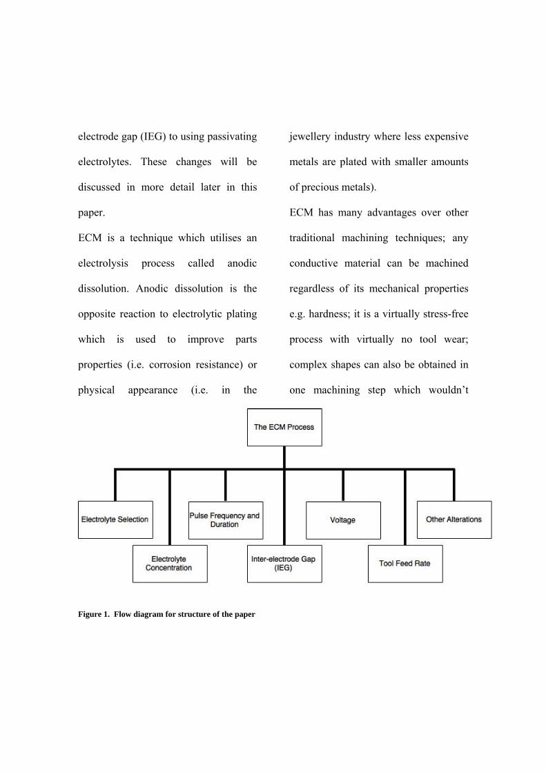
Figure 1. Flow diagram for structure of the paper
be ordinarily reached with conventional
machining techniques. This paper will
review research conducted in
electrochemical micromachining
(ECMM) and Figure 1 shows the flow
diagram for the structure of this paper.
2. The ECM process
Electrochemical machining is a
machining technique based on
electrolysis. Electrolysis uses the
passage of current between two
electrodes immersed in a conductive
solution, called an electrolyte, to
perform chemical reactions at the
electrodes. Current is passed between a
work piece, which is the positively
charged electrode, termed the anode and
a tool, which is the negatively charged
electrode, termed the cathode. Electrons
flow from the negatively charged
cathode toward the positively charged
anode. Electrons are carried through the
electrolyte in the form of ions.
Depending on the potential applied,
material can either be deposited or
removed from the electrodes.
Anodic dissolution removes material
according to Faraday’s Law (Equation
1):
(1)
Where m is the mass removed in g), Q
is the charge passed in C (Q=It where I
is current and t is time in s), F is
Faraday constant (96485 C mol-1), M is
the molar mass of the work piece in g
mol-1 and z is the valence number
(number of electrons transferred per
ion) which is a dimensionless number.
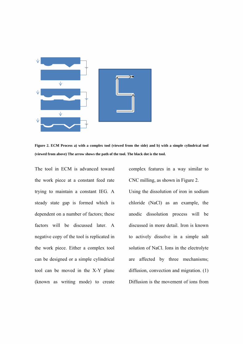
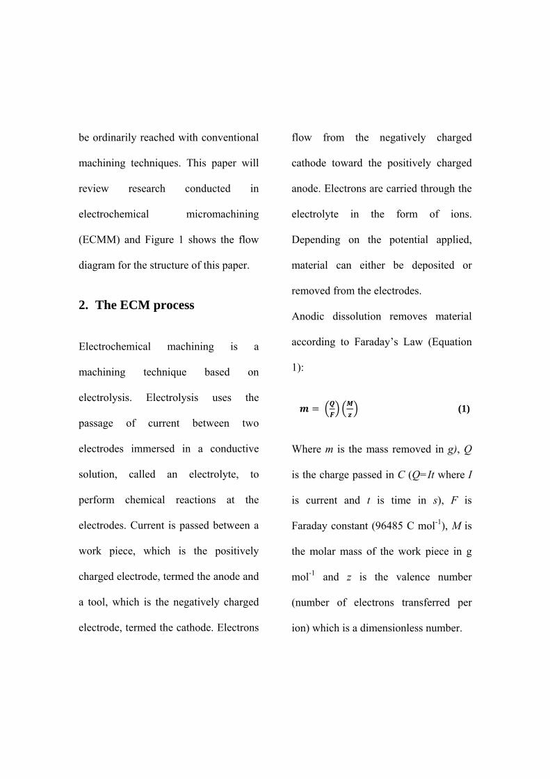
Figure 2. ECM Process a) with a complex tool (viewed from the side) and b) with a simple cylindrical tool
(viewed from above) The arrow shows the path of the tool. The black dot is the tool.
The tool in ECM is advanced toward
the work piece at a constant feed rate
trying to maintain a constant IEG. A
steady state gap is formed which is
dependent on a number of factors; these
factors will be discussed later. A
negative copy of the tool is replicated in
the work piece. Either a complex tool
can be designed or a simple cylindrical
tool can be moved in the X-Y plane
(known as writing mode) to create
complex features in a way similar to
CNC milling, as shown in Figure 2.
Using the dissolution of iron in sodium
chloride (NaCl) as an example, the
anodic dissolution process will be
discussed in more detail. Iron is known
to actively dissolve in a simple salt
solution of NaCl. Ions in the electrolyte
are affected by three mechanisms;
diffusion, convection and migration. (1)
Diffusion is the movement of ions from
a region of high concentration to a
lower concentration. Iron ions are
dissolved at the cathode surface and
diffuse across a thin, stagnant layer of
electrolyte at the electrode surface
toward the bulk electrolyte where iron
ion concentration is much lower.
Convection is movement induced by an
external force; in the case of ECM the
electrolyte is forced through the IEG at
high pressure and speed which carries
ions away from the IEG. Migration is
the movement of ions due to a potential
field, i.e. positive ions are
electrostatically attracted to a negatively
charged cathode tool and vice versa. In
this example, iron is dissolved at the
anode and hydrogen gas is evolved at
the cathode; the reactions are as
follows.
Anode: Fe Fe2+ + 2e-
Cathode: 2H+ + 2 e- H2↑
Iron is not deposited on the cathode as
the iron ions react with hydroxide ions
in the solution to form iron hydroxide
(Fe(OH)2) which is insoluble so
precipitates to form a sludge. The solid
reaction products are filtered from the
electrolyte. Figure 3 shows a visual
representation of the basic reactions
occurring during the ECM process.
The electrolyte is flushed through the
IEG to remove reaction products which
may cause sparks or short circuits
during machining due to increased
electrical resistivity in the IEG. The
electrolyte also removes heat from the
reaction region caused by Joule
Heating. If the reaction products are not
removed from the machining zone, a
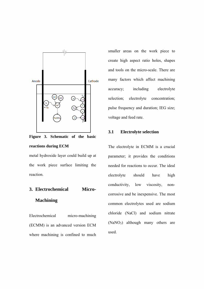
Figure 3. Schematic of the basic
reactions during ECM
metal hydroxide layer could build up at
the work piece surface limiting the
reaction.
3. Electrochemical Micro-
Machining
Electrochemical micro-machining
(ECMM) is an advanced version ECM
where machining is confined to much
smaller areas on the work piece to
create high aspect ratio holes, shapes
and tools on the micro-scale. There are
many factors which affect machining
accuracy; including electrolyte
selection; electrolyte concentration;
pulse frequency and duration; IEG size;
voltage and feed rate.
3.1 Electrolyte selection
The electrolyte in ECMM is a crucial
parameter; it provides the conditions
needed for reactions to occur. The ideal
electrolyte should have high
conductivity, low viscosity, non-
corrosive and be inexpensive. The most
common electrolytes used are sodium
chloride (NaCl) and sodium nitrate
(NaNO3) although many others are
used.
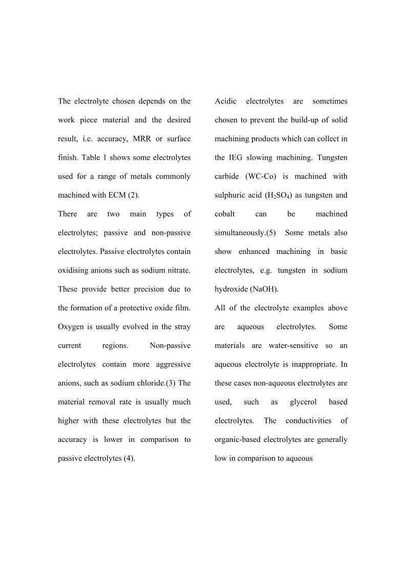
The electrolyte chosen depends on the
work piece material and the desired
result, i.e. accuracy, MRR or surface
finish. Table 1 shows some electrolytes
used for a range of metals commonly
machined with ECM (2).
There are two main types of
electrolytes; passive and non-passive
electrolytes. Passive electrolytes contain
oxidising anions such as sodium nitrate.
These provide better precision due to
the formation of a protective oxide film.
Oxygen is usually evolved in the stray
current regions. Non-passive
electrolytes contain more aggressive
anions, such as sodium chloride.(3) The
material removal rate is usually much
higher with these electrolytes but the
accuracy is lower in comparison to
passive electrolytes (4).
Acidic electrolytes are sometimes
chosen to prevent the build-up of solid
machining products which can collect in
the IEG slowing machining. Tungsten
carbide (WC-Co) is machined with
sulphuric acid (H2SO4) as tungsten and
cobalt can be machined
simultaneously.(5) Some metals also
show enhanced machining in basic
electrolytes, e.g. tungsten in sodium
hydroxide (NaOH).
All of the electrolyte examples above
are aqueous electrolytes. Some
materials are water-sensitive so an
aqueous electrolyte is inappropriate. In
these cases non-aqueous electrolytes are
used, such as glycerol based
electrolytes. The conductivities of
organic-based electrolytes are generally
low in comparison to aqueous
Table 1. Common electrolytes for a range of metals (2)
Metal Electrolyte Remarks
Aluminium and its alloys
NaNO3
(100-400 g dm-3)
Excellent surface finishing
Cobalt and its alloys
NaClO3
(100-600 g dm-3)
Excellent dimensional control, excellent surface finishing
Molybdenum NaOH (40-100 g dm-3)
NaOH consumed and must be added continuously
Nickel and its alloys
NaNO3 (100-400 g dm-3)
good surface finishing
NaClO3
(100-600 g dm-3)
good dimensional control, good surface finishing and low metal removal rate
Titanium and its alloys
NaCl (180 g dm-3) + NaBr (60 g dm-3) + NaF (2.5 g dm-3)
good dimensional control, good surface finishing and good machining rate
NaClO3
(100-600 g dm-3)
Bright surface finish, good machining rate above 24V
Tungsten NaOH (40-100 g dm-3)
NaOH consumed and must be added continuously
Steel and iron alloys
NaClO3
(100-600 g dm-3)
Excellent dimensional control, brilliant surface finish, high metal removal rate, fire hazards when dry
NaClO3(100-400 g dm-3)
Good dimensional control, lower fire hazard, good surface finish and good machining rate
NaNO3 (100-400 g dm-3)
Good dimensional control, fire hazard when dry, low metal removal rates, rough surface finish
electrolytes due to difficulties in
dissolving salts in them (1). This results
in lower machining rates but enhances
machining accuracy. High resistivity
electrolytes, such as glycerol-based
electrolytes, are commonly used for
electro-polishing, another variant of
ECM, as the difference in current
density between peaks and troughs is
greater, resulting in preferential
dissolution.(6)
3.2 Electrolyte Concentration
Electrolyte concentration also plays a
role in machining accuracy and
machining rates in ECMM. The
concentration of the electrolyte
determines its electrical conductivity;
the higher the concentration, the higher
the electrolyte conductivity. Many
studies have been conducted
researching how electrolyte
concentration affects ECM and ECMM
machining. (3,7–24) Accuracy is highly
important when machining micro-
features as smaller features require
smaller tolerances.
Bhattacharyya et al (3) observed that
with a lower concentration, higher
voltage and a moderate value for pulse-
on time the machining accuracy was
improved with a moderate MRR.
Ayyappan et al (7) observed that a
higher concentration lead to higher
material removal rates (MRR) and
better surface finish in an oxygenated
electrolyte of NaCl for 20MnCr5 steel
where gaseous oxygen was fed into the
electrolyte at differing pressure and
flow rate.
Ayyappan et al (8) also stated that a
higher electrolyte concentration ‘allow
for more ions for ionization’ which in
turn increases MRR. Ayyappan et al
(25) also indicated that the conductivity
of the electrolyte increased with
increasing concentration initially but
then levelled off as the concentration
was increased further. Bannard (9)
observed that the dissolution current
was higher for higher electrolyte
concentrations and the increase in
kinetics is why highly concentrated
electrolytes are employed in ECM.
Bhattacharyya and Munda (10)
presented results which showed that a
lower concentration in combination
with a larger machining voltage and a
‘moderate pulse on time’ produced
more accurate shapes at a moderate
MRR as the stray current effect is less.
Stray current occurs when the electrical
conductivity of the electrolyte allows
machining to reach areas of the work
piece at larger distances from the tool
electrode than is desirable creating a
less accurate machined shape.
Das and Saha (11) created cylindrical
micro-tools with ECMM form turning
where a rotating cylindrical tool was
moved toward a stationary block along
the x axis and found that the reaction
was non-uniform at higher electrolyte
concentrations, possibly due to the
difficulties in thoroughly cleaning the
IEG changing the conductivity of the
solution between the electrodes. This
led to shorter cylindrical tools formed in
higher concentration electrolytes in
comparison to the cylinder length in
lower concentrations. Higher
concentrations (> 3 M) in this study
were detrimental to the surface finish
due to the inefficiency cleaning the IEG
creating fluctuations in electrolyte
conductivity. They predicted an
increase in electrolyte agitation could
lead to an increase in tool length due to
better cleaning of the IEG, eliminating
conductivity fluctuations due to
dissolution products in the gap. Datta
(12) observed that the anion type and
electrolyte concentration affected the
MRR. The formation of a salt film on
the anode surface may occur more
readily at higher electrolyte
concentrations leading to a better
surface finish. This is because the
saturation limit will be more easily
reached at the electrode surface at
higher concentrations. Datta and
Landolt (13) later witnessed that the
current distribution is dependent on the
electrolyte concentration. This was
observed during electrochemical
deposition, the process analogous, yet
opposite, to ECM. During
electrochemical micro-drilling with a
mixed electrolyte of hydrochloric acid
(HCl) and sodium chloride (NaCl) Fan
et al (14) showed that the overcut
increased as the sodium chloride
concentration was increased. Overcut
occurs due to machining on the side gap
between the tool and work piece
resulting in a machined feature larger
than the tool used. Although above a
certain NaCl concentration (3.42 M) the
overcut began to decrease when in
combination with 0.3 M HCl. It cannot
be certain this is a trend which occurs
repeatedly in ECM as this was not
confirmed for the mixed electrolyte
containing 0.1 M HCl.
Ayyappan et al (25) added hydrogen
peroxide to a sodium chloride
electrolyte to machine 20MnCr5 steel
and found the MRR was increased with
the addition of the hydrogen peroxide.
Ayyappan et al (26) also added ferric
nitrate to a sodium chloride electrolyte
for the machining of 20MnCr5 stainless
steel. They observed an improvement in
MRR and surface roughness by
enhancing the ionisation of the
electrolyte.
Ghosal et al (15) created micro-
channels in SS 304 stainless steel with a
sulphuric acid electrolyte (H2SO4).
They found that the channel width
varied more with a less concentrated
electrolyte, decreasing the accuracy.
This was thought to occur due to the
small number of ions in the solution
available to take part in ECMM. Micro-
sparks could occur, due to the increase
in electrolyte resistivity which in turn
would increase the standard deviation of
the channel width. They also showed
that a very low concentration (0.1 M)
created a larger overcut than a 0.2 M
and 0.3 M electrolyte, yet the 0.3 M
electrolyte created a larger overcut than
the 0.2 M electrolyte. They concluded
for their application that 0.2 M H2SO4
was the optimal concentration.
Jain et al (16) using a sewing needle
with a tip of 47 µm diameter as the tool
to machine micro-holes, found that hole
diameter first increased as the
concentration increased but then
decreases. They attributed this to the
reduced ion mobility in solution
because of the high concentration. Their
set up allowed them to create a micro-
tool on the same machine as the hole
machining. This allowed them to
eliminate errors associated with micro-
tool clamping. In another case, Jain and
Gehlot (17) were investigating the
effects of several variables on the
produced shape with through-mask
ECMM. They observed that undercut
initially increased with concentration
but then began to decrease with an
increase in electrolyte concentration. In
this case it was explained by an increase
in current density which facilitated a
shorter machining time in the vertical
direction. This also meant the
machining time in the lateral direction
was reduced and here the effect of the
machining time dominated over the
increased current density, reducing the
undercut.
Rathod et al (18)created micro-grooves
in stainless steel using a sulphuric acid
electrolyte. Concentrations were only
varied between 0.15 and 0.30 M. Up to
0.25 M, they observed an increase in
overcut as the concentration was
increased. Above 0.25 M the overcut
began to reduce in size. This was
explained by way of an increase in gas
bubbles generated at the micro-tool
surface, decreasing machining.
Saravanan et al (19) observed the MRR
increased with electrolyte concentration
machining a super-duplex stainless steel
(SDSS) using a sodium nitrate
electrolyte with concentrations ranging
between 0.4 and 0.5 M.
Wang et al (20) stated that the
electrolyte concentration affected the
current density distribution which in
turn affected the current efficiency and
accuracy with a higher concentration
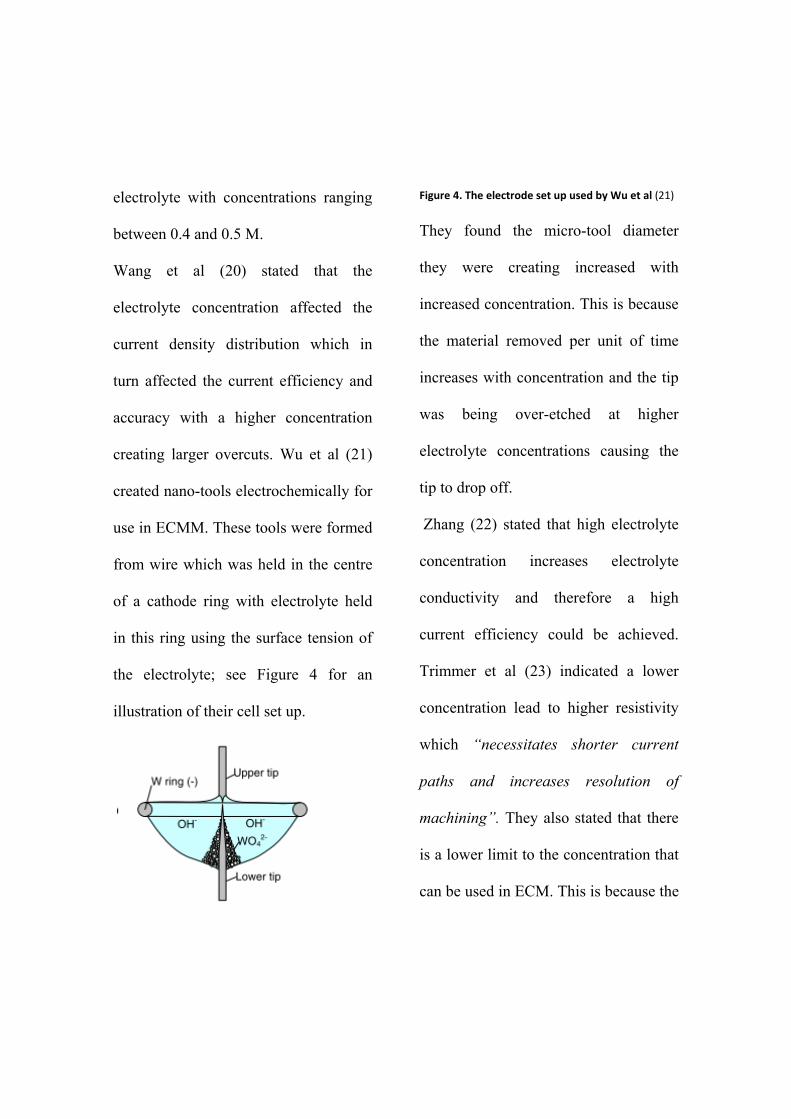
creating larger overcuts. Wu et al (21)
created nano-tools electrochemically for
use in ECMM. These tools were formed
from wire which was held in the centre
of a cathode ring with electrolyte held
in this ring using the surface tension of
the electrolyte; see Figure 4 for an
illustration of their cell set up.
Figure 4. The electrode set up used by Wu et al (21)
They found the micro-tool diameter
they were creating increased with
increased concentration. This is because
the material removed per unit of time
increases with concentration and the tip
was being over-etched at higher
electrolyte concentrations causing the
tip to drop off.
Zhang (22) stated that high electrolyte
concentration increases electrolyte
conductivity and therefore a high
current efficiency could be achieved.
Trimmer et al (23) indicated a lower
concentration lead to higher resistivity
which “necessitates shorter current
paths and increases resolution of
machining”. They also stated that there
is a lower limit to the concentration that
can be used in ECM. This is because the
ion content in the gap is not sufficient to
completely charge the double layer
capacitance. The double layer capacitor
is the charged layers at the work piece
and tool surfaces.
De Silva et al (24) observed that using a
lower electrolyte concentration
increased the Joule heating in the gap
which could cause process variation,
unless steps were taken to avoid this, for
example an increase in electrolyte flow
rate. They also performed experiments
to confirm that the current density
decreases much more quickly as the gap
is increased at lower concentrations,
showing that higher accuracy machining
can be achieved with lower
concentration electrolytes.
Most studies concluded a low
electrolyte concentration was more
beneficial when machining micro-
features as it kept conductivities to a
minimum which prevented large
machining overcuts even though a
compromise was made with respect to
the MRR and surface finish. This is
different to macro-ECM operations
where an importance is placed on the
machining rate and surface finish but
compromises on accuracy.
3.3 Pulse Frequency and
Duration
Precise electrochemical machining
(PECM) and ECMM utilise a pulsed
potential as supposed to the constant
potential used in ECM in order to
achieve better resolution. Pulses are
usually applied as a square wave with
variations in amplitude (voltage),
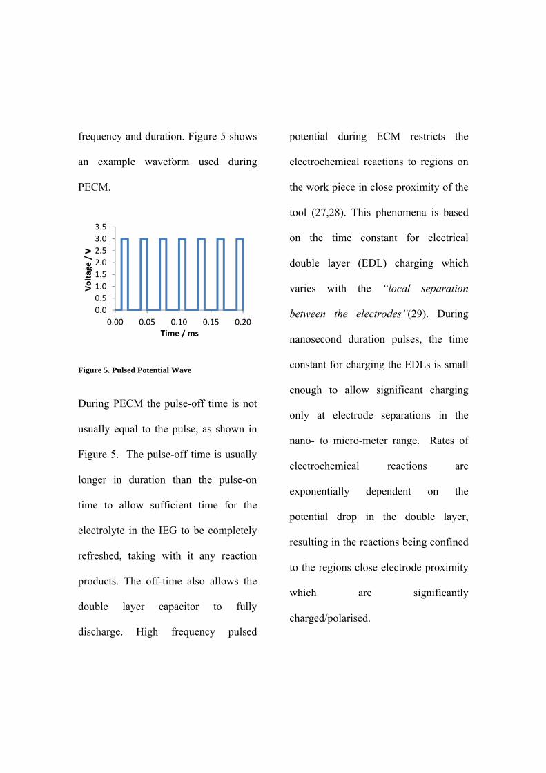
frequency and duration. Figure 5 shows
an example waveform used during
PECM.
Figure 5. Pulsed Potential Wave
During PECM the pulse-off time is not
usually equal to the pulse, as shown in
Figure 5. The pulse-off time is usually
longer in duration than the pulse-on
time to allow sufficient time for the
electrolyte in the IEG to be completely
refreshed, taking with it any reaction
products. The off-time also allows the
double layer capacitor to fully
discharge. High frequency pulsed
potential during ECM restricts the
electrochemical reactions to regions on
the work piece in close proximity of the
tool (27,28). This phenomena is based
on the time constant for electrical
double layer (EDL) charging which
varies with the “local separation
between the electrodes”(29). During
nanosecond duration pulses, the time
constant for charging the EDLs is small
enough to allow significant charging
only at electrode separations in the
nano- to micro-meter range. Rates of
electrochemical reactions are
exponentially dependent on the
potential drop in the double layer,
resulting in the reactions being confined
to the regions close electrode proximity
which are significantly
charged/polarised.
0.0
0.5
1.0
1.5
2.0
2.5
3.0
3.5
0.00 0.05 0.10 0.15 0.20
Voltage / V
Time / ms
The EDL, on both electrodes, is a
capacitor which becomes charged when
a voltage is applied between them. The
charging current has to pass through the
electrolyte, with the resistance
encountered proportional to the length
of the current path. Therefore the time
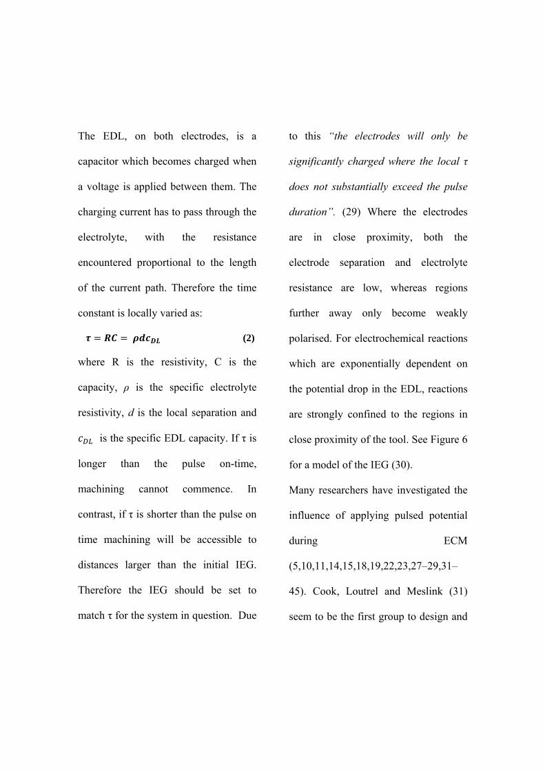
constant is locally varied as:
(2)
where R is the resistivity, C is the
capacity, ρ is the specific electrolyte
resistivity, d is the local separation and
is the specific EDL capacity. If τ is
longer than the pulse on-time,
machining cannot commence. In
contrast, if τ is shorter than the pulse on
time machining will be accessible to
distances larger than the initial IEG.
Therefore the IEG should be set to
match τ for the system in question. Due
to this “the electrodes will only be
significantly charged where the local τ
does not substantially exceed the pulse
duration”. (29) Where the electrodes
are in close proximity, both the
electrode separation and electrolyte
resistance are low, whereas regions
further away only become weakly
polarised. For electrochemical reactions
which are exponentially dependent on
the potential drop in the EDL, reactions
are strongly confined to the regions in
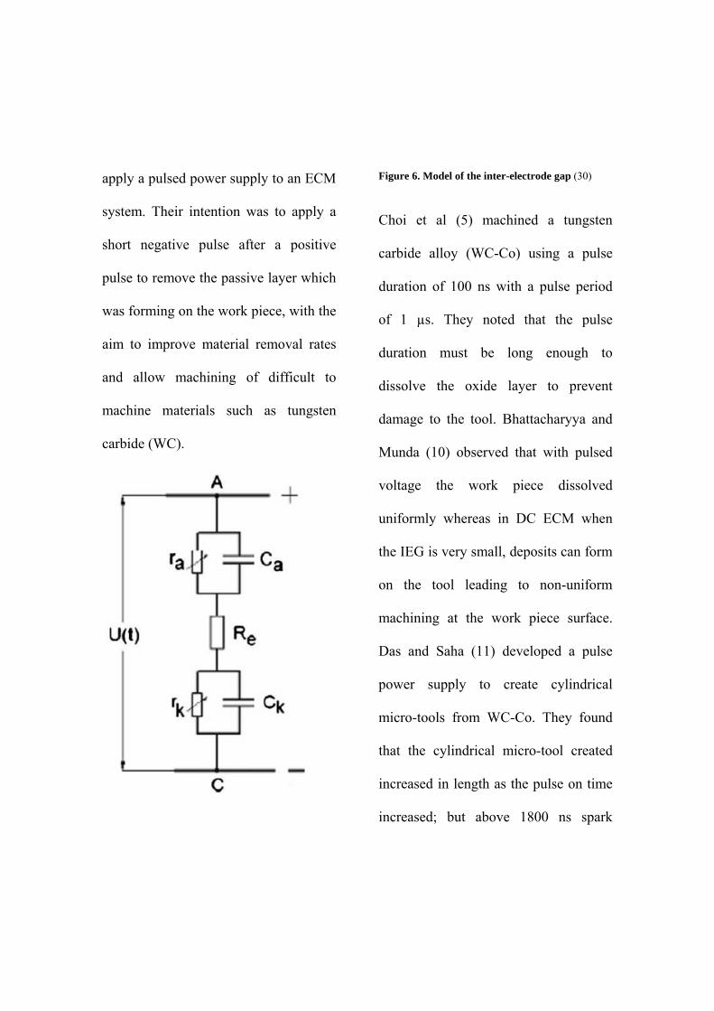
close proximity of the tool. See Figure 6
for a model of the IEG (30).
Many researchers have investigated the
influence of applying pulsed potential
during ECM
(5,10,11,14,15,18,19,22,23,27–29,31–
45). Cook, Loutrel and Meslink (31)
seem to be the first group to design and
apply a pulsed power supply to an ECM
system. Their intention was to apply a
short negative pulse after a positive
pulse to remove the passive layer which
was forming on the work piece, with the
aim to improve material removal rates
and allow machining of difficult to
machine materials such as tungsten
carbide (WC).
Figure 6. Model of the inter-electrode gap (30)
Choi et al (5) machined a tungsten
carbide alloy (WC-Co) using a pulse
duration of 100 ns with a pulse period
of 1 µs. They noted that the pulse
duration must be long enough to
dissolve the oxide layer to prevent
damage to the tool. Bhattacharyya and
Munda (10) observed that with pulsed
voltage the work piece dissolved
uniformly whereas in DC ECM when
the IEG is very small, deposits can form
on the tool leading to non-uniform
machining at the work piece surface.
Das and Saha (11) developed a pulse
power supply to create cylindrical
micro-tools from WC-Co. They found
that the cylindrical micro-tool created
increased in length as the pulse on time
increased; but above 1800 ns spark
machining was initiated causing a
deterioration in surface quality. Sparks
were probably formed here as the
increase in pulse on time increased the
electrolyte temperature enough to
induce boiling in the gap.
Fan et al (14) observed smaller over
cuts and straighter edged holes for
higher applied frequencies with the
same duty cycle, where the duty cycle is
defined as.
(3)
The same researchers also reported that
over cut increased with increased pulse
duration. This they attributed to the
increased polarisation of the EDL and
an increased production of hydrogen
evolution which results in non-uniform
machining.
Ghoshal et al (15) produced taper-less
holes in SS-304 stainless steel with a
low concentration sulphuric acid
electrolyte and a frequency of 5 MHz
and a duty cycle of 40 % which relates
to a pulse on time of 80 ns. Saravanan et
al (19) observed that MRR increased as
duty cycle was increased but decreased
as frequency was increased. Increasing
the duty cycle increases the percent of
each cycle for which a voltage is
applied. Increasing the frequency
decreases the time period of each cycle.
In this case they did not consider how
these parameters affected the machining
over-cut.
Zhang (22) witnessed that a short pulse
on-time applied over a long machining
time (i.e. long off-time) led to a higher
current efficiency at the macro-scale.
This is most probably due to the
complete renewal of the electrolyte
during the pulse off time. Trimmer et al
(23) utilised short voltage pulses to
restrict stray machining to create high
aspect ratio holes and complex patterns.
They observed that a shorter pulse in
combination with a low electrolyte
concentration gave the best machining
resolution for the conditions studied.
Schuster et al (29) is credited with
applying pulsed voltages to improve
resolution in ECM and take the
applicability of ECM into micro- and
nano technologies. Their calculations
show a pulse of 30 ns should produce
machining with a resolution of 1 µm.
They experimentally observed that
resolution was linearly dependant on
both pulse length and electrolyte
concentration. They achieved a
resolution of 1.4 µm experimentally in a
copper work piece.
Meijer and Veringa (32) observed that
PECM resulted in a better surface finish
and tool reproduction than ECM. Van
Damme et al and Smets et al (33,35)
created models of the PECM process
investigating the effects of local
electrolyte concentration variations.
They observed an off time > 90 ms, for
the system they were studying, allowed
the electrolyte in the IEG to be
completely refreshed to bulk conditions,
meaning each pulse is independent of
the last pulse. As the pulses increase in
duration, a viscous salt layer builds on
the work piece surface, eliminating
water from the electrode surface. This
prevents oxygen evolution, increasing
the machining efficiency as the pulse
duration increases because metal
dissolution becomes the only reaction at
the end of the pulse.
Zhang et al (34) produced complex
shapes in nickel (Ni) sheets using a 40
ns pulse. There was no stray machining
observed due to the short length of the
voltage pulse applied and large pulse off
time (460 ns) in comparison to the on
time.
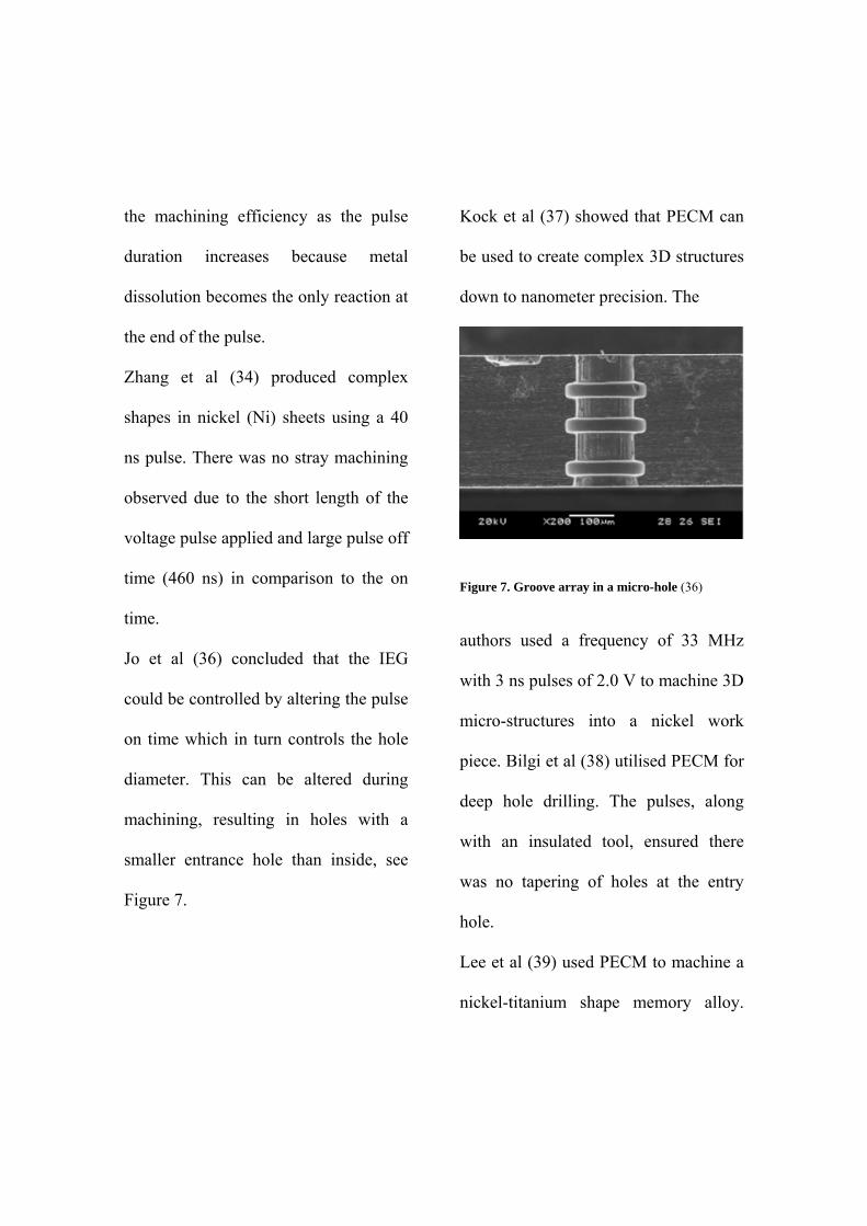
Jo et al (36) concluded that the IEG
could be controlled by altering the pulse
on time which in turn controls the hole
diameter. This can be altered during
machining, resulting in holes with a
smaller entrance hole than inside, see
Figure 7.
Kock et al (37) showed that PECM can
be used to create complex 3D structures
down to nanometer precision. The
Figure 7. Groove array in a micro-hole (36)
authors used a frequency of 33 MHz
with 3 ns pulses of 2.0 V to machine 3D
micro-structures into a nickel work
piece. Bilgi et al (38) utilised PECM for
deep hole drilling. The pulses, along
with an insulated tool, ensured there
was no tapering of holes at the entry
hole.
Lee et al (39) used PECM to machine a
nickel-titanium shape memory alloy.
The authors saw an increase of
machining inaccuracy when the duty
cycle was raised above 50 % with a
pulse on time varying between 10 and
75 µs. Xu et al (40) observed that as the
pulse duration was increased from 25
ns to 40 ns the surface roughness
remained low but above 40 ns the
surface roughness increased. The
authors attributed this to there being
more electrolyte products in the gap.
Cagnon et al (28) performed PECM
with two steps; a fast rough cut,
followed by a slower fine cut. This was
achieved by varying the pulse on time
from 143 ns for the rough cut to 50 ns
for the fine cut. The authors created
several complex, 3D micro-structures in
stainless steel. Bhattacharyya (41)
reported that PECM results in more
accurate machining as it eliminates
reaction products, including heat, from
the IEG during the pulse off time
maintaining a consistent electrolyte
conductivity and therefore an equal
MRR across the machining profile.
Rajurkar et al (27) produced a model to
ascertain the IEG characteristics. They
observed that for very short pulse times
the resolution was improved. Sun et al
(42) modified a PECM process to
include a very short cathodic pulse in
order to remove the anodic film that can
form at the work piece surface. This
would allow an improved surface finish.
They called this “modulated reverse
electric field ECM (MREF-ECM)”.
This process also benefits from the
improved dimensional accuracy
observed with PECM.
Datta and Landolt (43) developed an
electrochemical saw with a pulsed
voltage. They report that the use of a
pulsed voltage negates the use of a
complex electrolyte pumping systems
whilst applying extremely high current
densities as the off time allows removal
of reaction products and effects of Joule
heating from the inter-electrode gap.
Mathew and Sundaram (44) created
micro-tools with PECM starting with a
wire with a diameter of 50 µm which
was reduced to 13.7 µm; achievable due
to the high control of the machining
process seen in PECM. This method
could be used for on-the-machine tool
fabrication.
Rajurkar, Zhu and Wei (45) created a
model to predict the minimum
machining allowance or depth which
confirmed the effectiveness of using
short pulses to enhance resolution. In
this case a pulse duration of 1-3 ms with
a duty cycle of 50 % was sufficient for
the desired accuracy. Rathod et al (18)
applied the same frequency pulses but
varied the duty cycle, which changes
the pulse on time and the pulse on/off
time ratio. A higher duty cycle resulted
in a larger over cut but surface
roughness and width variation along the
length of the machined channel
improved with increased frequency and
decreased duty cycle.
3.4 Inter-Electrode Gap
(IEG)
As discussed in the above section, the
IEG is a critical parameter and
maintaining a constant gap during
machining is a challenge many
researchers have tried to combat
through modelling and in-line
measurement systems
(3,4,10,11,22,27,29,30,34,36–
38,41,44,46–60). The gap maintained in
PECM and ECMM is much smaller
than in DC-ECM, in the range of 5-50
µm compared to 100-600 µm. (3,22)
This is because a smaller IEG leads to
better resolution, crucial for ECMM.
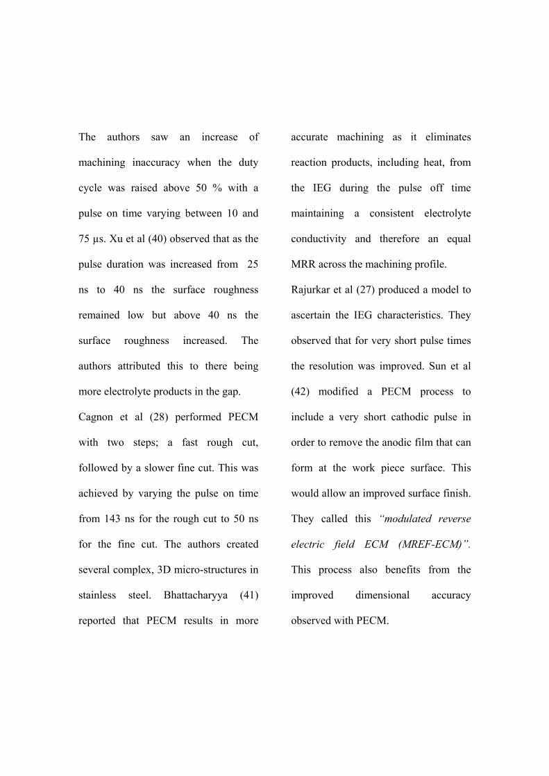
Figure 8 shows voltage profile across
the IEG. The smaller the IEG the
smaller the applied potential has to be to
reach the machining voltage as the
ohmic drop caused by the electrolyte
resistance is reduced. This is used to the
researchers’ advantage. There is
preferential dissolution of material
which is closer to the tool electrode due
to the higher potential creating a higher
current density at that point.
Researchers investigated how the IEG
size affected several factors during
machining. Bilgi et al (38) observed that
a smaller IEG led to a higher MRR. Jo
et al (36) realised the resolution varied
with the pulse voltage and duration.
Figure 8. Potential profile within the IEG (61)
They used this observation to create
complex internal shapes, Figure 7.
Bhattacharyya et al (41) reduced the
IEG to micrometer scale by lowering
the voltage and electrolyte
concentration, resulting in higher
resolution machining. Zhang et al (34)
found it much easier to control the IEG
when nanosecond voltage pulses were
applied due to the small amount of
material removed with each pulse.
Zeng et al (54) observed a better surface
finish with a smaller IEG. Smaller IEGs
result in higher current densities
especially at peaks on the surface,
preferentially dissolving those, levelling
the surface. Jain et al (15) maintained a
constant IEG during machining which
resulted in micro-channels with high
accuracy. Kock et al (37) showed that
with very short pulses, the localisation
worsened linearly with pulse duration
and Sharma et al (59) observed that a
relatively high feed rate with a low
applied voltage resulted in a small IEG.
Kozak et al (58) proposed that using
smaller surface area tools facilitated a
smaller IEG as the influence of heat and
gas generation would be minimised.
This in turn improved machining
resolution.
Rajurkar et al (46) created a model to
determine the minimum IEG with the
onset of electrolyte boiling being the
limiting factor. If the electrolyte boils,
gas bubbles are generated and
diminishes the volume of electrolyte in
the IEG which could cause sparks. The
same author (27) had previously
modelled the IEG and the development
of bubbles in the IEG and how this
affected machining. They reported a
very thin layer of bubbles or an even
distribution of bubbles throughout the
gap resulted in equal machining across
the whole electrode interface. If the
concentration of the bubbles was greater
at one side of the gap e.g. at the
electrolyte outlet, the machining rate
would be reduced due to an increase in
electrolyte resistivity.
Jain and Pandey (56) suggested the IEG
acted as a pure ohmic resistor. Kozak et
al and Fang et al (48,50) created models
which predicted the IEG shape and size
with Fang modelling the current
distribution lines within the IEG too.
Clifton (51) also modelled the IEG but
used C-functions to “map out
parameter interdependence, resulting
from non-ideal conditions”. This
approach eliminated the need for time
consuming iterative trials used to
determine the ideal tool shape.
Jain et al (49,55) and Mathew et al (44)
created models of the IEG to design an
ideal tool shape based on predictions for
the desired anode shape, see Figure 9
for a flow diagram demonstrating all
considerations in the model. Jain and
Pandey (52) developed a model of the
IEG in ECM. They noted a decrease in
the IEG resulted in a greater
temperature and conductivity rise in the
electrolyte. Kozak et al (30) developed
a model calculation whereby the electric
field within the IEG is described by
Laplace’s equation to define the
limiting gap size for a given pulse
length, voltage and electrolyte
concentration. during machining. Da
Silva Neto (4) noted improper control of
the IEG led to poor tool replication; in
their case the surface finish was
negatively affected and Rajurkar et al
(60) noted it was important for proper
control of the IEG to prevent short
circuits or arcing occurring during
machining. The authors highlighted the
importance of having gap monitoring
and control systems. Schuster et al
(29), Bhattacharyya and Munda (10)
and Das and Saha (11) all used a current
detection method to maintain the IEG.
A small voltage was applied between
the tool and work piece; the tool was
slowly moved towards the work piece,
monitoring the current. When it is
registered that electrodes are in contact,
the tool is stopped and retracted by the
chosen IEG distance. The current was
monitored as a way to control the IEG
during machining as the surface area
was not expected to change.
Wang et al (53) developed a soft-
computer numerical control system
which monitored the process and
automated functions such as gap
detection and adjustment. Labib et al
(57) developed a fuzzy logic control
system, whereby the short circuit
situation could be avoided which the
researchers thought could ultimately
lead to a better surface finish. Muir et al
(47) utilised a ultrasonic method which
would measure the IEG without
disrupting the machining process. The
ultrasonic transmit/receive transducer
gave information regarding the work
piece thickness. Using this information
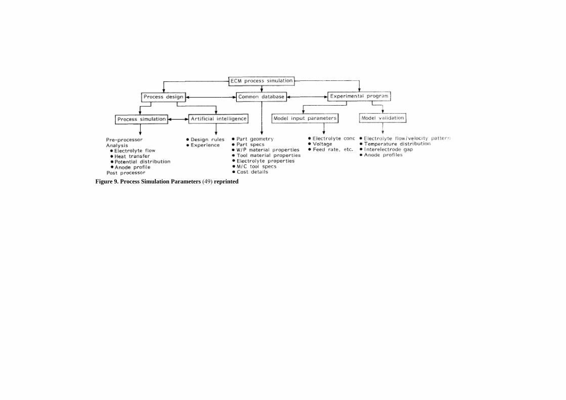
Figure 9. Process Simulation Parameters (49) reprinted
in tandem with the tool position, the
IEG could be calculated.
3.5 Voltage
From Faraday’s Law, see Equation 1,
one can predict that the applied voltage
in ECM will affect the amount of
material removed through the
relationship V = IR where V is the
voltage and R is the resistance. (24) In
this case R is the resistance of the
electrolyte. With these two equations, it
is possible to presume that a higher
voltage will result in a higher current
passing which would increase the
amount of material removed during the
same time period with a lower voltage.
Many researchers have demonstrated
this to be true.
(8,10,14,18,19,21,24,30,31,38,40,43,55,
62–64) Wagner and Wang (20,65) also
stated the current density is a function
of the applied voltage.
However, when the potential is raised
above a particular voltage (dependent
on the work piece material and
electrolyte combination) the MRR
decreased. They explained this by an
increase in hydrogen gas generation at
the tool electrode. These bubbles,
trapped in the IEG, increased the
resistivity of the electrolyte, decreasing
the current density at the work piece,
decreasing MRR. (10,18,38)
Although a higher voltage leads to a
higher MRR it has other effects which
may be detrimental to machining. Cook
(31), Cagnon (28), Datta (43) and Bilgi
(62) all noted that damage to the tool
occurred when high voltages were used
caused by sparking which affected
machining accuracy. Tandon (64) was
investigating electrochemical spark
machining but observed that a higher
voltage increased the rate of tool wear.
Machining resolution also decreased as
the machining voltage was increased,
illustrating that lower voltages are more
appropriate for ECMM to keep over cut
to a minimum. Bhattacharyya (10), Fan
(14), Ghoshal (15), V. Jain (15), Rathod
(18), Kozak (30,48), Datta (43),Fang
(50), Bilgi (38,62,67), Tandon (64), N.
Jain (66), Rao (68) all observed an
increased overcut when machining with
a higher voltage, which resulted in more
rounded edges. Sharma (59) stated
“good holes can be obtained by a
combination of low voltage and
comparatively high feed rate”. Acharya
(63) stated that the optimum voltage for
a high MRR was higher than the
optimum voltage required for
geometrical accuracy.
Several authors also observed improved
surface finish with a higher applied
voltage. (6,7,28,40,54)
Xu (40) noted an initial improvement in
surface finish as the voltage increased.
However, in their case, as the voltage
was increased above 6 V the surface
roughness increased. Sjöström (69)
stated that a lower applied voltage may
lead to a better surface finish but at the
cost of a lower MRR. However,
Sjöström was using a non-aqueous
electrolyte, suggesting the solvent was
reacting undesirably with the work
piece surface at higher voltages.
Choi (5), Bhattacharyya (10,41), Kozak
(30), Cook(31) and Jo (36) all stated
that the IEG could be lowered by the
application of a lower machining
voltage, which in turn increased the
machining accuracy. Kozak (30)
showed that the limiting gap becomes
smaller with a smaller applied voltage.
The limiting gap is the minimum IEG
that can be used at the settings chosen.
Jo (36) took advantage of this
knowledge to create complex internal
structures, see Figure 7.
Inman (6) and Zhang (22) realised a
higher machining voltage was necessary
to break through passive layers at the
work piece surface when using strongly
passivating materials or electrolytes.
Bhattacharyya (10) recognized an
increase in Joule heating upon the
application of a higher voltage. This
caused changes in the local electrolyte
conductivity, leading to an inaccurate
tool replication in the work piece. Das
(11) noted an increased cylindrical
length, when fabricating cylindrical
micro tools, with increased voltage up
to 21 V. Above 21 V, the authors
suspected the end of the micro tool was
falling away due to increased machining
at the electrolyte air interface.
Bhattacharyya suggests this is due to air
bubbles rising to the surface where they
burst, minimising the diffusion layer
which in turn increases the current
density. (70)
The direction of the reaction at the work
piece (deposition or dissolution) at a
given potential can be predicted by the
Nernst equation, Equation 4.
. (4)
Where is the formal potential of the
couple O/R, R is the gas constant, T is
the temperature, n is the number of
electrons involved, F is the Faraday
constant and and are the
concentrations of the oxidant and
reductant respectively. (1) Datta (12)
observed that at potentials above the
limiting current density new anodic
reactions could occur, notably a change
in dissolution valency or oxygen
evolution at the work piece.
3.6 Tool Feed Rate
The tool feed rate is a crucial parameter
in ECMM to minimise overcut and
maximise MRR. Cook et al (31) first
observed that the feed rate was
dependent on the current density, with
Singh (71) also stating that the feed rate
influences the IEG. More material is
removed per unit time when the current
density is higher which facilitates a
higher tool feed rate.
Many papers report the use of a
constant feed rate during ECM. The aim
was to use a feed rate which matched
the dissolution rate so the IEG could be
kept constant throughout machining.
(47,72) Researchers found if a very high
feed rate was used the IEG would
rapidly decrease in width, eventually
causing a short circuit, creating sparks
which can damage the tool or work
piece. (18,28,34,43,52,62) Ghoshal (15)
realised the optimum feed rate was the
maximum feed rate which did not
induce sparking between the electrodes.
Authors observed that the MRR
increased with feed rate
(4,7,52,54,55,63,68) but it could lead to
non-uniform dissolution as reported by
Jain (52). This could be due to the
increased temperature rise when the
feed rate is increased. The increase in
feed rate can lead to electrolyte boiling
or choking in the IEG. (52,55)
Many researchers studying the effect of
feed rate on the ECM process noted a
decrease in the machining overcut as the
tool feed rate was increased.
(4,14,16,43,48,54,56,62) This is
probably due to the observation that a
higher feed rate decreased the IEG
(38,48,51,71), which, as previously
discussed, increases machining
resolution. Some also reported a
decrease in surface roughness with an
increase in feed rate. (4,54) In a couple
of papers, authors reported an increase
in dimensional inaccuracy with an
increase in feed rate (68,72). Kozak (48)
also reported above a certain feed rate,
63 mm/min, the sharpness of the edges
decreased.
Whilst most authors reported the use of
a fixed feed rate during machining,
Labib (57) and Jain (72) maintained a
constant IEG by adjusting the feed rate
accordingly. They used a fuzzy logic
control where real-time decisions could
be made by the computer controller.
This prevented the equilibrium IEG
becoming established, possibly allowing
a smaller IEG than the equilibrium gap
to be maintained throughout machining.
This is a promising technique which
could improve machining accuracy.
3.7 Other Alterations to ECM
Having discussed all of the common
parameters controlled for precise ECM
above, other alterations to the ECM
process will now be explored. All of the
alterations aimed to improve MRR or
decrease machining overcut.
One of the most common alterations
made to ECMM was the addition of
vibrations to either the work piece or
the tool. (40,41,73) Observations were
made that the application of ultrasonic
vibrations (USV) enhanced mass
transport and improved surface
roughness both when amplitude and
frequency were increased.
Qu et al (74) pulsated the electrolyte
instead of vibrating one of the
electrodes. The authors reported an
improvement in the surface roughness
and increased MRR when the
electrolyte pulsating frequency was
increased. A maximum frequency of 20
Hz was applied.
Trying to improve machining precision,
researchers began investigating ways to
restrict and control the potential field
between the tool and the work piece.
Tools were insulated which prevented
machining in the side gap. Another
alteration was the development of a
dual-pole tool. The cathodic tool was
initially insulated with an insoluble
anodic layer on top. This reduces the
chances of over-cut due to stray
machining by changing the electric field
within the gap. (3,75)
4 Conclusion
A vast amount of research has already
been conducted over the past 50+ years,
observing the effects of electrolyte type,
concentration, pulse frequency and
duration, IEG, voltage, tool feed rate
and other alterations such as the
application of ultrasonic vibrations to
one of the electrodes. High
concentrations and applied voltages lead
to a larger machining over-cut but can
lead to highly polished surfaces. The
tool feed rate is matched to the material
removal rate to maintain the IEG which
allows even machining and prevents
rounding of hole entrances.
Vibrations can be applied to either of
the electrodes or to the electrolyte
which helps to clear the IEG of
machining products, either solid,
aqueous or gaseous. The gas bubbles
cannot grow as large when there is
insonation. USV also improves the mass
transport to and from the work piece
surface which therefore improves the
machining rate of ECM.
There is no unified logic for IEG
control. This is due to the random
nature of gap conditions affected by the
electrolyte condition and machining
products in the gap. This makes gap
control very difficult and subject to
differing control ideas at present. Along
with IEG control, there is a need for
high speed over-current protection
systems to avoid sparking, and short
circuit damage to both the electrodes
and the machine electronics.
Very little work has been conducted on
ECM machining of semiconductor
materials outside of doped silicon
materials. A wide range of
semiconductor materials are being used
more commonly in electronic
equipment, some of which are brittle
and difficult to machine with
conventional machining processes. It is
proposed to determine whether ECM is
a suitable machining method for some
of these semiconductors, including
indium antimonide (InSb) and gallium
arsenide (GaAs).
Another interesting field is the
machining of superconductors. Most
high temperature superconductors are
based on the perovskite crystal structure
with internal layers throughout the
structure which are crucial to the
superconductivity of the material.
Traditional, contact machining
techniques can damage these layers
through the application of physical
pressure on the material. ECM is an
ideal technique for machining
superconductors as it is a non-contact,
stress-free and heat-free technique.
Also, there has been no work, to the
author’s knowledge, investigating the
effect of crystal structure, comparing
the results obtained in ECM for
polycrystalline, monocrystalline and
amorphous materials. This would be of
interest with the aim to developing more
precise machining results and
manufacturing of MEMS devices as
well as testing the boundaries of
archived roughness and feature size.
5 Acknowledgment
The research reported in this paper is
supported by the European Commission
within the project “Minimizing Defects
in Micro-Manufacturing Applications
(MIDEMMA)” (FP7-2011-NMP-ICT-
FoF-285614).


![[XLS] · Web view91021 272602 22 12391 8253.681818181818 4137.318181818182 163415 101510 264925 22 12042.045454545454 7427.954545454545 4614.090909090909 150270 97760 248030 22 11274.09090909091](https://img.pdfslide.us/doc/110x75/5b2b27be7f8b9a9c648b4ae7/xls-web-view91021-272602-22-12391-8253681818181818-4137318181818182-163415.jpg)