Embed Size (px)
Citation preview

Pilot’s GuideEngine Data Management
EDM-930
Primary
TSOCopyright 2010 J.P. Instruments, Inc.
All Rights Reserved
J.P. INSTRUMENTS INC.
Information: P. O. Box 7033Huntington Beach, CA 92646Factory: 3185 B AirwayCosta Mesa, CA 92626(714) 557-5434 Fax (714) 557-9840www.jpinstruments.com
Printed in the United States of America Rev I 10-12
Last printed 5/14/2013 9:17:00 AM
Table of Contents
Section 1 - Getting Started 1Display View Angle 2List of abbreviations and acronyms 3Fuel Flow Computer Basics 3Control Button Basics 4Display Screen Basics 4Remote Auxiliary Display Basics 5RPM and MAP Display Basics 5Linear Bar Graph Display Basics 5Scanner® Display Basics 6LeanFind Basics 6
Section 2 - Interpreting Data 7Operation for each Phase of Flight 7Typical Normal Measurements 9
Section 3 - Displays and Controls 12Control Buttons 12RPM and MAP Displays 14Scanner Displays 14Remote Auxiliary Display 17Hobbs Display 17Dimming the Display 17
Section 4 - Operating Modes 18Automatic Mode 18Manual Mode 19
Section 5 - LeanFind 20LeanFind Procedure—General Explanation 24Expanded Leaning Procedures 28
Section 6 - Fuel Flow Operation 29Fuel Management 29Start Up Fuel 30Resetting ‘USD’ 32Resetting ‘USD’ 33Resetting ‘USD’ 34Trip Mode (Accumulate Trip Totalizer) 34Scanner Fuel Flow Display Select 34
Section 7 - Alarms 35Non-primary Alarm Priority 35
Section 8 - Memory and Data Download 36Downloading Data from the EDM 37Transferring data from the USB Flash Drive to a PC 37
Section 9 - First Time Setup and Customization 38Pilot Programming Mode 40Adjusting the HP Constant for Rich of Peak Operation 42Adjusting the MAP 42Adjusting the HP Value 43Fuel Flow K factor 43Programming Trip Mode 45Setting the GPS Com Format 46
Section 10 - Custom Key Card 46Section 11 - Setting Fuel Calibration Points 47
Getting Started…Collecting Fuel Level Calibration Data using the EDM as ameter. 48After you have collected your data…Entering / Editing Fuel Level CalibrationData 49Troubleshooting the EDM 52Troubleshooting the EDM 53Diagnostic Testing on Startup and During Flight 53Diagnostic Messages 54
Section 12 - Appendices 56TSO-only differences from Primary Instruments 56Shock Cooling 57Rear Apron Connector Locations 58Connector pin assignments 58Connector pin assignments 59Navigation Data Formats 60Navigation Data Ports for GPS Comm 60Interface connections to selected GPS models 60
Section 13 - Technical Support 61Index 62QUICK REFERENCE 66
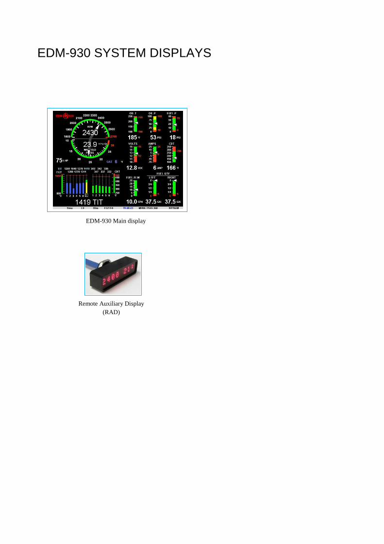
EDM-930 SYSTEM DISPLAYS
EDM-930 Main display
Remote Auxiliary Display
(RAD)
Product Features
Hands-free, automatic scanning LeanFind finds the first and last cylinder to peak with true
peak detect—eliminates false peaks Displays both leaned temperature below peak and peak Battery voltage with alarm Amperes (load or charge/discharge meter) Programmable alarm limits Exhaust Gas Temperatures (EGTs) to stable 1°F resolution DIF low to high EGT with alarm Shock cooling monitored on every cylinder Fast response probes Non-volatile long term memory Records and stores data up to 30 hours Post-flight data retrieval Data retrieval software Oil pressure Oil temperature Turbine inlet temperature, if applicable (optional) Outside air temperature Compressor discharge temperature (optional) Carburetor temperature or induction temperature (optional) Fuel pressure, if applicable Fuel level Voltage, Resistive or Capacitive (frequency) Fuel Flow
Solid-state rotor fuel flow transducer Fuel quantity in gallons, kilograms, liters, or pounds Low fuel quantity alarm Low fuel time alarm GPS interface Instantaneous fuel flow rate Total amount of fuel consumed Total fuel remaining Time to empty at the current fuel flow rate
RPM and manifold pressure Automatically calculates percent horsepower Hobbs® timer Remote Auxiliary Display (RAD)
Section 1 - Getting Started
Important Note!
You must have the remote auxiliary display—RAD— installedon the instrument panel of your aircraft. This is required for FAAcertification of the EDM-930 as a primary instrument. Upon startup, the RAD displays the make and model of you aircraft, whichmust be verified before you can rely on the EDM-930 for use asthe primary engine instrument cluster. The RAD also willcontinuously notify you of any alarm conditions, regardless ofwhether you have cleared them on the EDM-930 display.
This is not an option!
This is a summary of basic operation. Detailed descriptions of alloperations appear later in this Pilot’s Guide.
EDM-930 primary instruments have preset alarm limits and cautionaryranges (user cannot change them) typically for the followingmeasurements: oil temperature, oil pressure, fuel pressure, fuel quantity,cylinder head temperature, turbine inlet temperature, manifold pressure,and RPM. Your EDM-930 contains a custom Key Card. For Primaryconfigurations, the Key Card activates the primary engine instrumentabilities of your engine monitor.
Note: Fuel quantity gauges must be calibrated to the aircraft and will notbe functional until the fuel calibration process has been performed.

For Your Safe Flight Page 2
Display View Angle
The best view angle for the pilot is in the horizontal mode with thebuttons on the bottom. The best Portrait mode is with the buttons on theright.
View angles are per the table below:
Horizontal Left 65 Degrees
Viewing Right 65 Degrees
angle Vertical Up 50 Degrees
Down 60 Degrees
For Your Safe Flight Page 3
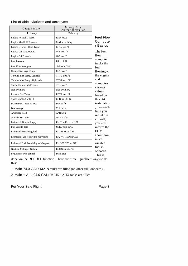
List of abbreviations and acronyms
Fuel FlowComputer Basics
The fuelflowcomputertracks thefuelflowing tothe engineandcomputesvariousvaluesbased onthis. Atinstallation, then eachtime yourefuel theaircraft,you mustinform theEDMabout howmuchuseablefuel isonboard.This is
done via the REFUEL function. There are three ‘Quickset’ ways to dothis:
1. Main 74.0 GAL: MAIN tanks are filled (no other fuel onboard).
2. Main + Aux 94.0 GAL: MAIN +AUX tanks are filled.
Gauge FunctionMessage Area
Alarm AbbreviationPrimary Primary
Engine rotational speed RPM xxxx
Engine Manifold Pressure MAP xx.x in hg
Engine Cylinder Head Temp CHT2 xxx oF
Engine Oil Temperature O-T xxx oF
Engine Oil Pressure O-P xxx oF
Fuel Pressure F-P xx PSI
Fuel Flow to engine F-F xx.x GPH
Comp. Discharge Temp. CDT xxx oF
Turbine inlet Temp. Left side TIT-L xxxx oF
Turbine Inlet Temp. Right side TIT-R xxxx oF
Single Turbine Inlet Temp. TIT xxxx oF
Non-Primary Non-Primary
Exhaust Gas Temp. EGT2 xxxx oF
Shock Cooling of CHT CLD xx o/MIN
Differential Temp. of EGT DIF xx oF
Bus Voltage Volts xx.x
Amperage Load AMPS xx
Outside Air Temp. OAT xx oF
Estimated Time to Empty Est. T to E xx:xx H:M
Fuel used to date USED xx.x GAL
Estimated Remaining fuel Est. REM xx GAL
Estimated Fuel required to Waypoint Est. WP REQ xx GAL
Estimated Fuel Remaining at Waypoint Est. WP RES xx GAL
Nautical Miles per Gallon ECON xx.x MPG
Brightness, Dim control DIM/BRT
For Your Safe Flight Page 4
3. Adjust? 0.0 GAL: Partial fuel added to existing quantity.
See page 29 for expanded information on the refueling process.
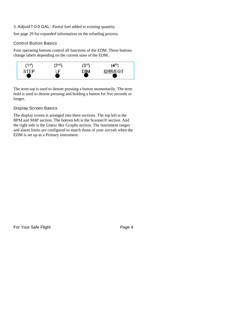
Control Button Basics
Four operating buttons control all functions of the EDM. These buttonschange labels depending on the current state of the EDM..
The term tap is used to denote pressing a button momentarily. The termhold is used to denote pressing and holding a button for five seconds orlonger.
Display Screen Basics
The display screen is arranged into three sections. The top left is theRPM and MAP section. The bottom left is the Scanner® section. Andthe right side is the Linear Bar Graphs section. The instrument rangesand alarm limits are configured to match those of your aircraft when theEDM is set up as a Primary instrument.
For Your Safe Flight Page 5
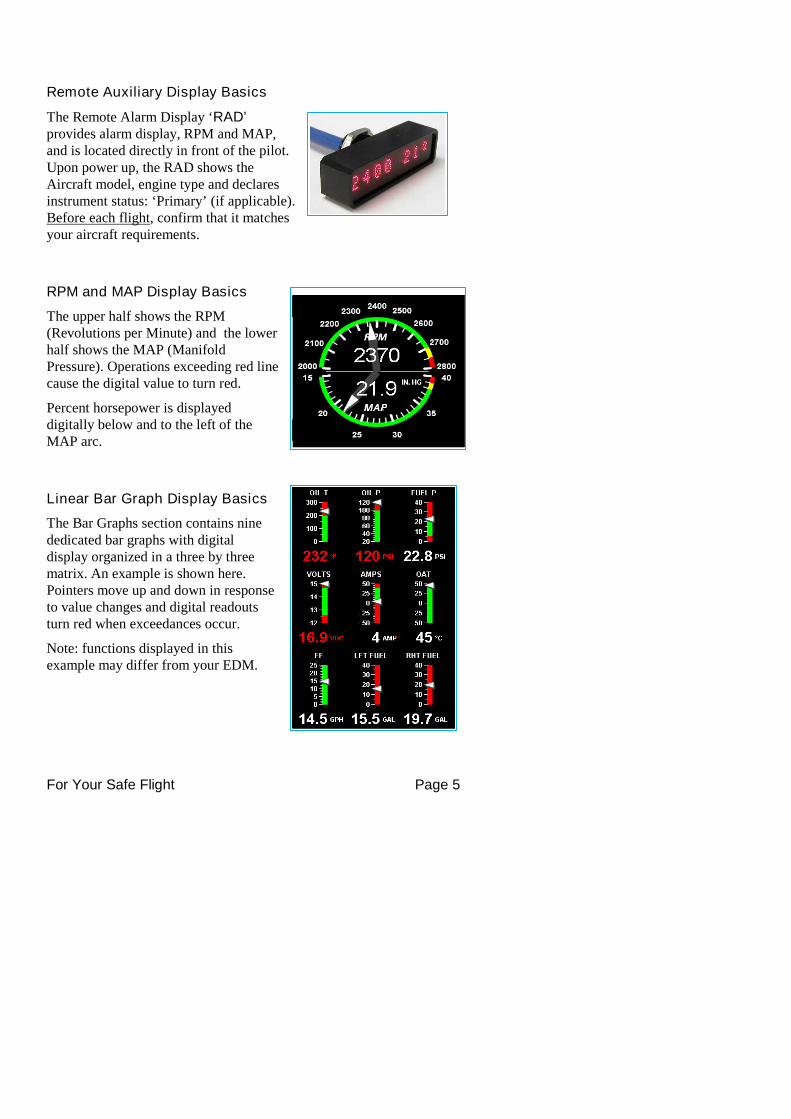
Remote Auxiliary Display Basics
The Remote Alarm Display ‘RAD’provides alarm display, RPM and MAP,and is located directly in front of the pilot.Upon power up, the RAD shows theAircraft model, engine type and declaresinstrument status: ‘Primary’ (if applicable).Before each flight, confirm that it matchesyour aircraft requirements.
RPM and MAP Display Basics
The upper half shows the RPM(Revolutions per Minute) and the lowerhalf shows the MAP (ManifoldPressure). Operations exceeding red linecause the digital value to turn red.
Percent horsepower is displayeddigitally below and to the left of theMAP arc.
Linear Bar Graph Display Basics
The Bar Graphs section contains ninededicated bar graphs with digitaldisplay organized in a three by threematrix. An example is shown here.Pointers move up and down in responseto value changes and digital readoutsturn red when exceedances occur.
Note: functions displayed in thisexample may differ from your EDM.
For Your Safe Flight Page 6
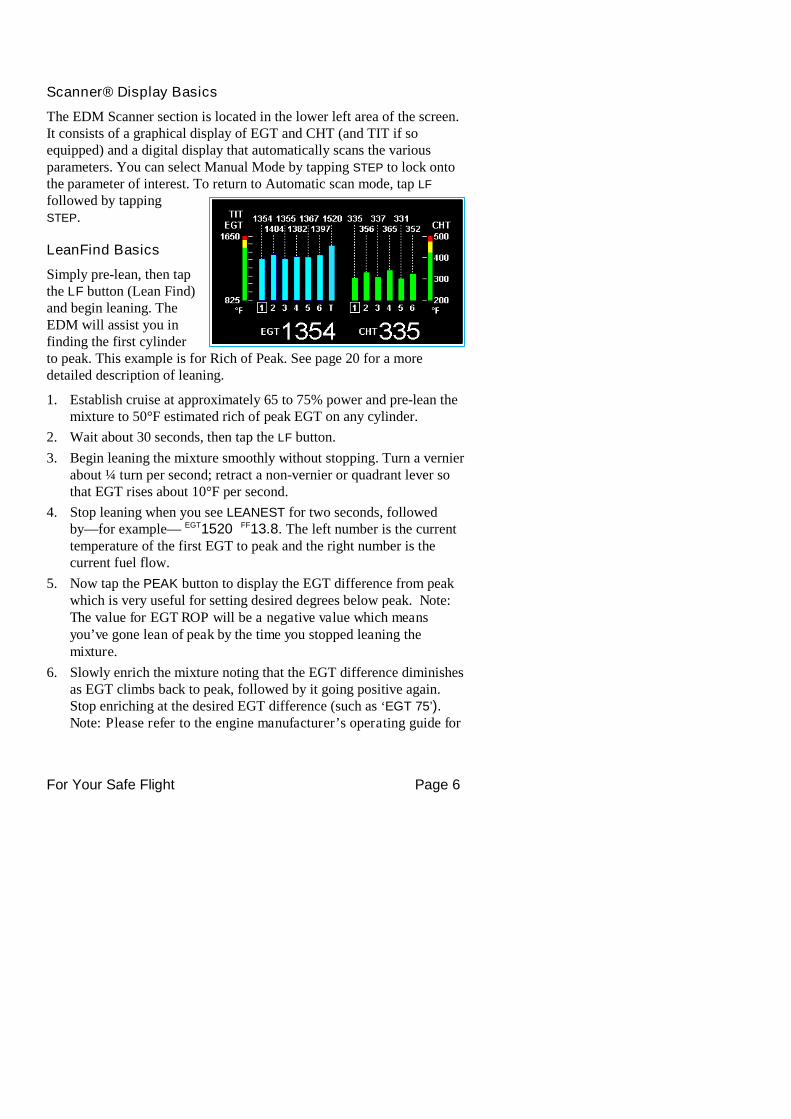
Scanner® Display Basics
The EDM Scanner section is located in the lower left area of the screen.It consists of a graphical display of EGT and CHT (and TIT if soequipped) and a digital display that automatically scans the variousparameters. You can select Manual Mode by tapping STEP to lock ontothe parameter of interest. To return to Automatic scan mode, tap LF
followed by tappingSTEP.
LeanFind Basics
Simply pre-lean, then tapthe LF button (Lean Find)and begin leaning. TheEDM will assist you infinding the first cylinderto peak. This example is for Rich of Peak. See page 20 for a moredetailed description of leaning.
1. Establish cruise at approximately 65 to 75% power and pre-lean themixture to 50°F estimated rich of peak EGT on any cylinder.
2. Wait about 30 seconds, then tap the LF button.
3. Begin leaning the mixture smoothly without stopping. Turn a vernierabout ¼ turn per second; retract a non-vernier or quadrant lever sothat EGT rises about 10°F per second.
4. Stop leaning when you see LEANEST for two seconds, followedby—for example— EGT1520 FF13.8. The left number is the currenttemperature of the first EGT to peak and the right number is thecurrent fuel flow.
5. Now tap the PEAK button to display the EGT difference from peakwhich is very useful for setting desired degrees below peak. Note:The value for EGT ROP will be a negative value which meansyou’ve gone lean of peak by the time you stopped leaning themixture.
6. Slowly enrich the mixture noting that the EGT difference diminishesas EGT climbs back to peak, followed by it going positive again.Stop enriching at the desired EGT difference (such as ‘EGT 75’).Note: Please refer to the engine manufacturer’s operating guide for
For Your Safe Flight Page 7
the correct value for EGT difference rich of peak operation at 75%and 65%
7. You can also see what the peak EGT was by holding the PEAK
button.
8. Tap STEP to exit the Lean Find Mode.
Section 2 - Interpreting Data
Operation for each Phase of Flight
(worth adding to your run-up checklist)
EngineRun-Up
Suggested setup: Set engine to run-up RPM
Normalize view: Manual mode
Verify: uniform rise of about 50°F in all EGTs in single
magneto operation.
uniform rise of EGTs with application of the mixture
control.
Be alert for: unusually low voltage (less than nominal battery
voltage) cold OIL and normal oil pressure abnormally high CHT
large drop in EGT on one cylinder in single magnetooperation—may be fouled spark plug.
For Your Safe Flight Page 8
Take-Off,Climb, andFullThrottleOperations
Suggested setup:
Standard view Automatic mode
Verify: EGTs and CHTs consistent with past climbs. EGTs
should be in the 1100 to 1300°F range (100° to 300°Fcooler than cruise) due to fuel cooling.
Be alert for: high EGT in one cylinder, 300°F above the others may
indicate plugged injector or leaking manifold gasket ona carbureted engine. At high density altitude an overlyrich mixture can significantly reduce engine power.
If all EGT columns go off scale to the top of thecolumn, be sure you are not in Normalize view, asindicated by the symbol NRM above the Scanner®section.
Cruise
After the engine is warmed up, use LeanFind to lean themixture.
Suggested setup: Normalize view Automatic mode
Be alert for: uneven EGTs (injected engines). Make fine
adjustments to throttle, then RPM, then mixture tolevel the display columns.
abnormal patterns of EGTs and CHT. (see EngineDiagnosis Chart on page 10).
Descent
Suggested setup: Standard view Manual mode
Be alert for: CLD: shock cooling alarm is set to -60°F. Average
cool rates of -40°F/minute to -50°F/minute are normal,depending on the engine size.
For Your Safe Flight Page 9
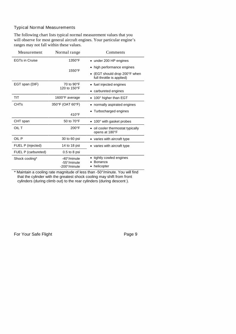
Typical Normal Measurements
The following chart lists typical normal measurement values that youwill observe for most general aircraft engines. Your particular engine’sranges may not fall within these values.
Measurement Normal range Comments
EGTs in Cruise 1350°F
1550°F
under 200 HP engines
high performance engines
(EGT should drop 200°F whenfull throttle is applied)
EGT span (DIF) 70 to 90°F120 to 150°F
fuel injected engines
carbureted engines
TIT 1600°F average 100° higher than EGT
CHTs 350°F (OAT 60°F)
410°F
normally aspirated engines
Turbocharged engines
CHT span 50 to 70°F 100° with gasket probes
OIL T 200°F oil cooler thermostat typicallyopens at 180°F
OIL P 30 to 60 psi varies with aircraft type
FUEL P (injected) 14 to 18 psi
FUEL P (carbureted) 0.5 to 8 psi
varies with aircraft type
Shock cooling* -40°/minute-55°/minute
-200°/minute
tightly cowled engines Bonanza helicopter
* Maintain a cooling rate magnitude of less than -50°/minute. You will findthat the cylinder with the greatest shock cooling may shift from frontcylinders (during climb out) to the rear cylinders (during descent ).
For Your Safe Flight Page 10
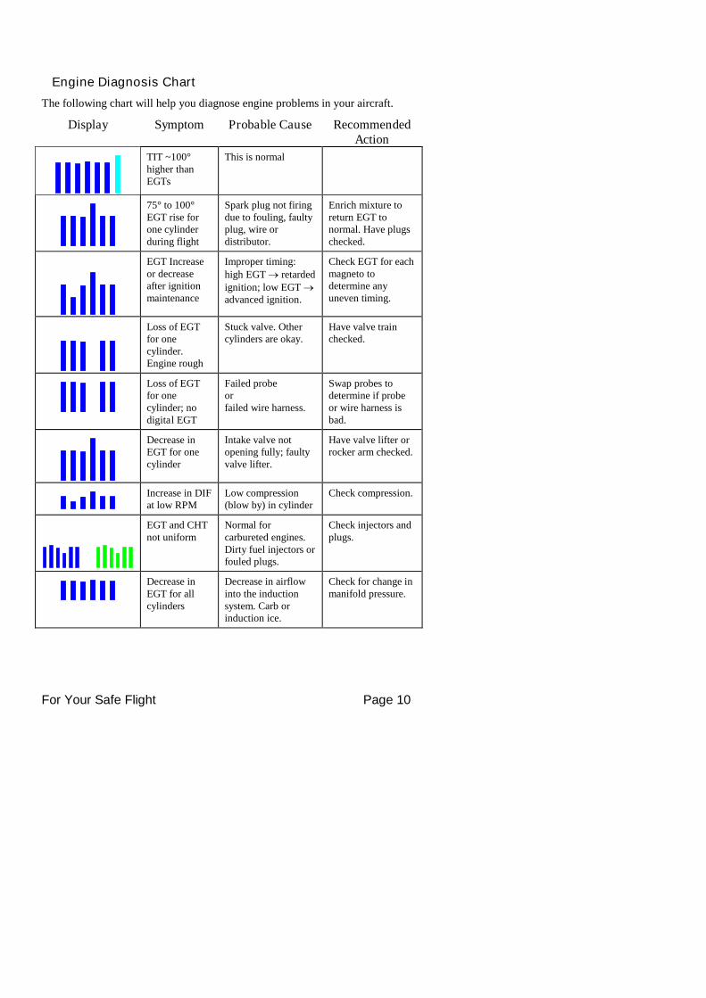
Engine Diagnosis Chart
The following chart will help you diagnose engine problems in your aircraft.
Display Symptom Probable Cause RecommendedAction
TIT ~100°higher thanEGTs
This is normal
75° to 100°EGT rise forone cylinderduring flight
Spark plug not firingdue to fouling, faultyplug, wire ordistributor.
Enrich mixture toreturn EGT tonormal. Have plugschecked.
EGT Increaseor decreaseafter ignitionmaintenance
Improper timing:high EGT retardedignition; low EGT advanced ignition.
Check EGT for eachmagneto todetermine anyuneven timing.
Loss of EGTfor onecylinder.Engine rough
Stuck valve. Othercylinders are okay.
Have valve trainchecked.
Loss of EGTfor onecylinder; nodigital EGT
Failed probeorfailed wire harness.
Swap probes todetermine if probeor wire harness isbad.
Decrease inEGT for onecylinder
Intake valve notopening fully; faultyvalve lifter.
Have valve lifter orrocker arm checked.
Increase in DIFat low RPM
Low compression(blow by) in cylinder
Check compression.
EGT and CHTnot uniform
Normal forcarbureted engines.Dirty fuel injectors orfouled plugs.
Check injectors andplugs.
Decrease inEGT for allcylinders
Decrease in airflowinto the inductionsystem. Carb orinduction ice.
Check for change inmanifold pressure.
For Your Safe Flight Page 11
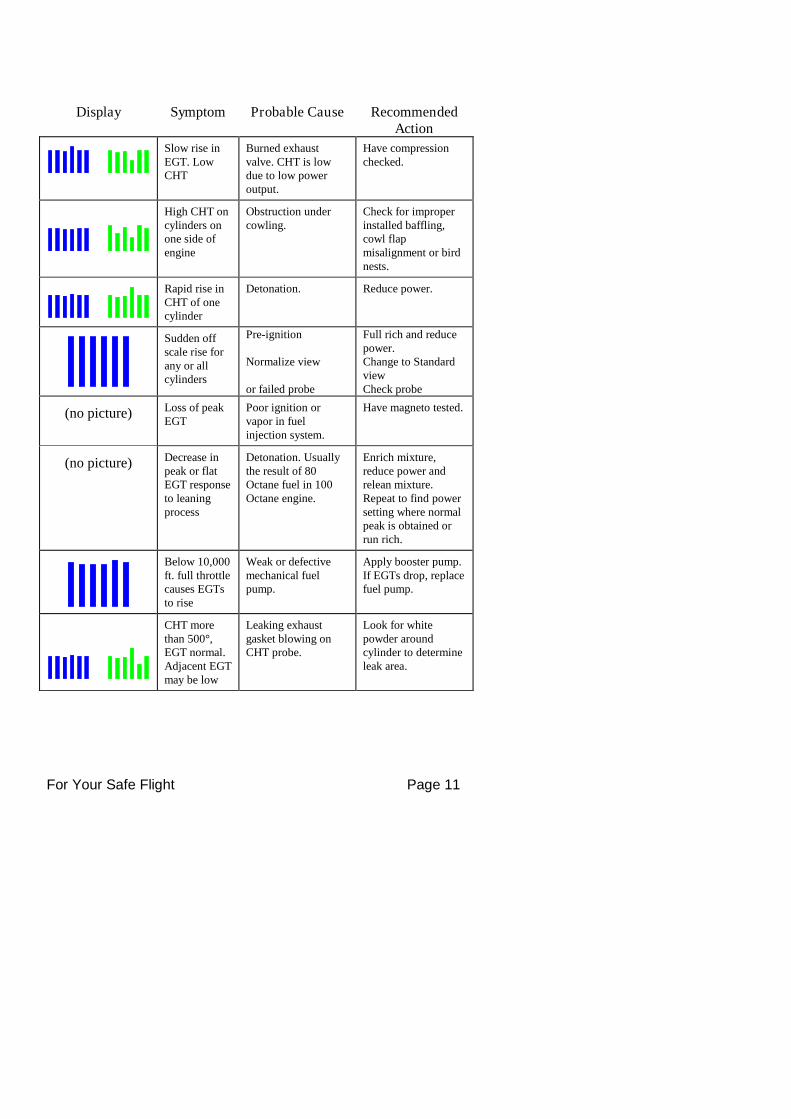
Display Symptom Probable Cause RecommendedAction
Slow rise inEGT. LowCHT
Burned exhaustvalve. CHT is lowdue to low poweroutput.
Have compressionchecked.
High CHT oncylinders onone side ofengine
Obstruction undercowling.
Check for improperinstalled baffling,cowl flapmisalignment or birdnests.
Rapid rise inCHT of onecylinder
Detonation. Reduce power.
Sudden offscale rise forany or allcylinders
Pre-ignition
Normalize view
or failed probe
Full rich and reducepower.Change to StandardviewCheck probe
(no picture) Loss of peakEGT
Poor ignition orvapor in fuelinjection system.
Have magneto tested.
(no picture) Decrease inpeak or flatEGT responseto leaningprocess
Detonation. Usuallythe result of 80Octane fuel in 100Octane engine.
Enrich mixture,reduce power andrelean mixture.Repeat to find powersetting where normalpeak is obtained orrun rich.
Below 10,000ft. full throttlecauses EGTsto rise
Weak or defectivemechanical fuelpump.
Apply booster pump.If EGTs drop, replacefuel pump.
CHT morethan 500°,EGT normal.Adjacent EGTmay be low
Leaking exhaustgasket blowing onCHT probe.
Look for whitepowder aroundcylinder to determineleak area.
For Your Safe Flight Page 12
Section 3 - Displays and Controls
The EDM monitors engine temperatures, pressures and voltages, assistsin adjusting the fuel/air mixture, and helps diagnose enginemalfunctions. There are multiple components of the user interface:
Four front panel operating buttons below the bottom of the display. RPM and MAP display in the upper left corner of the display Scanner analog display including cylinder number and index square
in the lower left corner of the display Scanner digital display for numeric readouts and messages at the
bottom left Bar graph displays on the right half of the display
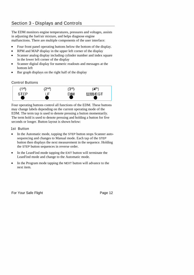
Control Buttons
Four operating buttons control all functions of the EDM. These buttonsmay change labels depending on the current operating mode of theEDM. The term tap is used to denote pressing a button momentarily.The term hold is used to denote pressing and holding a button for fiveseconds or longer. Button layout is shown below:
1st Button
In the Automatic mode, tapping the STEP button stops Scanner auto-sequencing and changes to Manual mode. Each tap of the STEP
button then displays the next measurement in the sequence. Holdingthe STEP button sequences in reverse order.
In the LeanFind mode tapping the EXIT button will terminate theLeanFind mode and change to the Automatic mode.
In the Program mode tapping the NEXT button will advance to thenext item.
For Your Safe Flight Page 13
2nd Button
In Automatic or Manual modes, tapping the LF button will activatethe LeanFind mode.
In the LF mode holding the LF button after peak EGT is found willdisplay the peak EGT.
In Automatic or Manual modes holding the LF button for threeseconds will toggle between Standard and Normalize (NRM) views.
In the programming mode, tapping the PLUS or MINUS button willallow you to edit a parameter value.
Holding LF during power up will display the primary alarm limitsafter the self-test is complete.
1st and 2nd Buttons
Holding both the STEP and LF buttons simultaneously for fiveseconds will enter the pilot programming mode.
Just after entering Lean Find Mode (but before any EGT has risen),holding both First and Second buttons for five seconds will togglebetween LOP or ROP leaning modes.
Tapping both the STEP and LF buttons simultaneously in Manualmode toggles to ‘include’ or ‘exclude’ the displayed non-primarymeasurement from the Automatic mode. Note: Measurements arenever excluded from the Manual mode.
3rd Button
Tapping DIM (brightness decreases) or holding DIM (brightnessincreases) allows decrease or increase brightness respectively.
2nd
and 3rd
Buttons
Holding both the LF and DIM buttons simultaneously will display theHobbs readings. Tap button labeled NEXT to see additionalinformation screens.
4th Button ( ALL/EGT/FF )
Select what is shown during Scanner auto-sequence. Choices areALL, EGT or FF. Highlighted one is what is active.
For Your Safe Flight Page 14
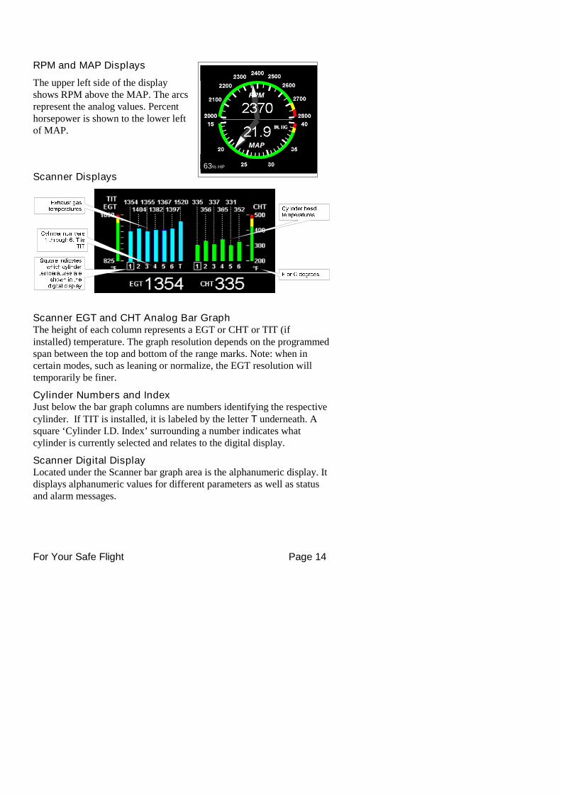
RPM and MAP Displays
The upper left side of the displayshows RPM above the MAP. The arcsrepresent the analog values. Percenthorsepower is shown to the lower leftof MAP.
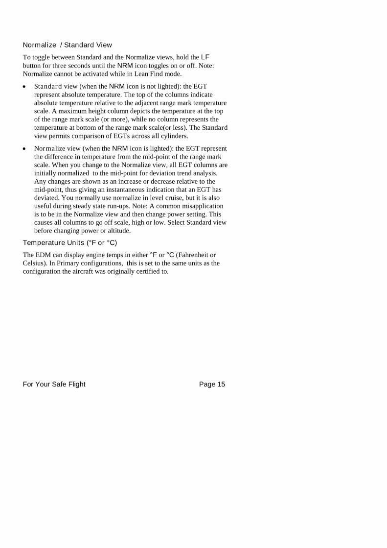
Scanner Displays
Scanner EGT and CHT Analog Bar GraphThe height of each column represents a EGT or CHT or TIT (ifinstalled) temperature. The graph resolution depends on the programmedspan between the top and bottom of the range marks. Note: when incertain modes, such as leaning or normalize, the EGT resolution willtemporarily be finer.
Cylinder Numbers and IndexJust below the bar graph columns are numbers identifying the respectivecylinder. If TIT is installed, it is labeled by the letter T underneath. Asquare ‘Cylinder I.D. Index’ surrounding a number indicates whatcylinder is currently selected and relates to the digital display.
Scanner Digital DisplayLocated under the Scanner bar graph area is the alphanumeric display. Itdisplays alphanumeric values for different parameters as well as statusand alarm messages.
63% HP
For Your Safe Flight Page 15
Normalize / Standard View
To toggle between Standard and the Normalize views, hold the LFbutton for three seconds until the NRM icon toggles on or off. Note:Normalize cannot be activated while in Lean Find mode.
Standard view (when the NRM icon is not lighted): the EGTrepresent absolute temperature. The top of the columns indicateabsolute temperature relative to the adjacent range mark temperaturescale. A maximum height column depicts the temperature at the topof the range mark scale (or more), while no column represents thetemperature at bottom of the range mark scale(or less). The Standardview permits comparison of EGTs across all cylinders.
Normalize view (when the NRM icon is lighted): the EGT representthe difference in temperature from the mid-point of the range markscale. When you change to the Normalize view, all EGT columns areinitially normalized to the mid-point for deviation trend analysis.Any changes are shown as an increase or decrease relative to themid-point, thus giving an instantaneous indication that an EGT hasdeviated. You normally use normalize in level cruise, but it is alsouseful during steady state run-ups. Note: A common misapplicationis to be in the Normalize view and then change power setting. Thiscauses all columns to go off scale, high or low. Select Standard viewbefore changing power or altitude.
Temperature Units (°F or °C)
The EDM can display engine temps in either °F or °C (Fahrenheit orCelsius). In Primary configurations, this is set to the same units as theconfiguration the aircraft was originally certified to.
For Your Safe Flight Page 16
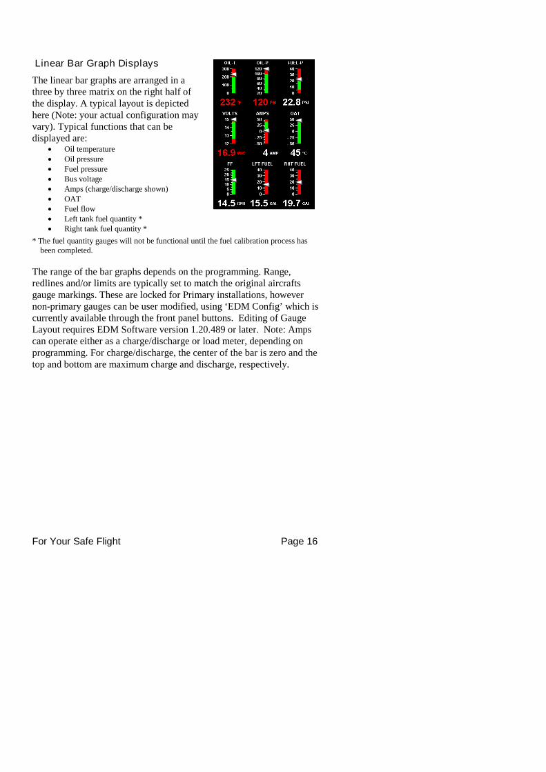
Linear Bar Graph Displays
The linear bar graphs are arranged in athree by three matrix on the right half ofthe display. A typical layout is depictedhere (Note: your actual configuration mayvary). Typical functions that can bedisplayed are:
Oil temperature Oil pressure Fuel pressure Bus voltage Amps (charge/discharge shown) OAT Fuel flow Left tank fuel quantity * Right tank fuel quantity *
* The fuel quantity gauges will not be functional until the fuel calibration process hasbeen completed.
The range of the bar graphs depends on the programming. Range,redlines and/or limits are typically set to match the original aircraftsgauge markings. These are locked for Primary installations, howevernon-primary gauges can be user modified, using ‘EDM Config’ which iscurrently available through the front panel buttons. Editing of GaugeLayout requires EDM Software version 1.20.489 or later. Note: Ampscan operate either as a charge/discharge or load meter, depending onprogramming. For charge/discharge, the center of the bar is zero and thetop and bottom are maximum charge and discharge, respectively.
For Your Safe Flight Page 17
HOBBS Times
EDM HOBBS: 127.4
Engine HOBBS: 120.6
Flight HOBBS: 2.7
Flight Duration: 02:42:21
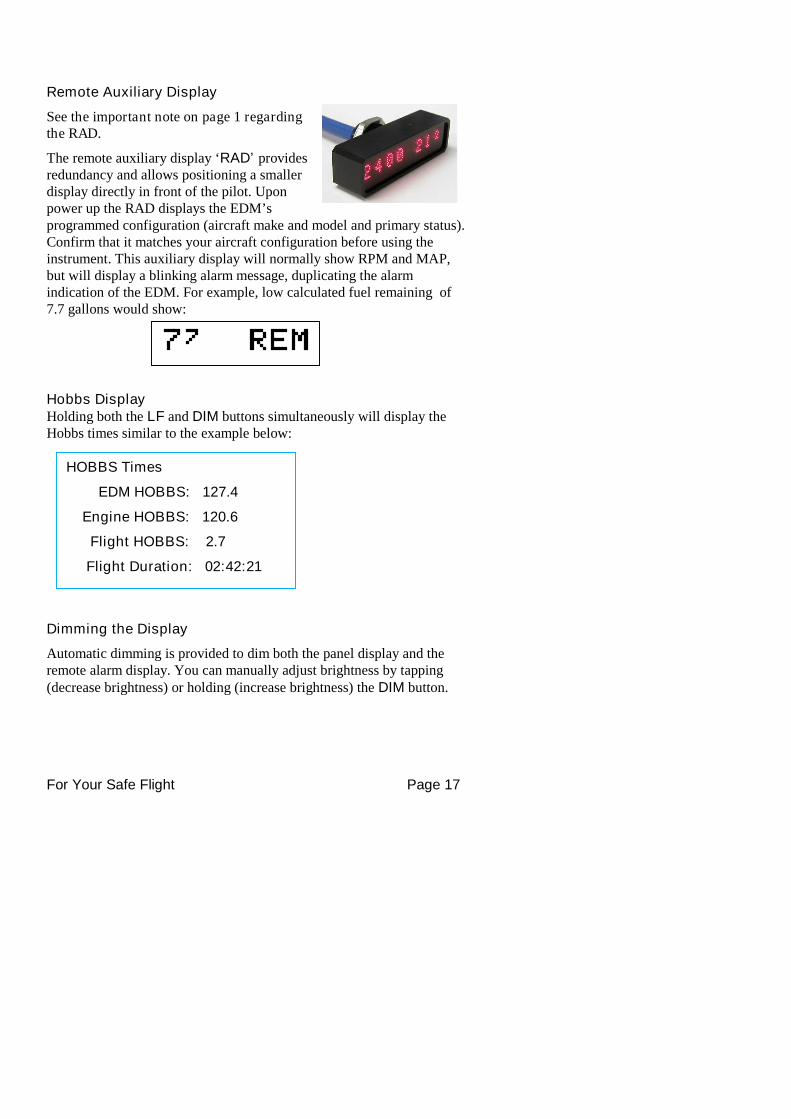
Remote Auxiliary Display
See the important note on page 1 regardingthe RAD.
The remote auxiliary display ‘RAD’ providesredundancy and allows positioning a smallerdisplay directly in front of the pilot. Uponpower up the RAD displays the EDM’sprogrammed configuration (aircraft make and model and primary status).Confirm that it matches your aircraft configuration before using theinstrument. This auxiliary display will normally show RPM and MAP,but will display a blinking alarm message, duplicating the alarmindication of the EDM. For example, low calculated fuel remaining of7.7 gallons would show:
Hobbs DisplayHolding both the LF and DIM buttons simultaneously will display theHobbs times similar to the example below:
Dimming the Display
Automatic dimming is provided to dim both the panel display and theremote alarm display. You can manually adjust brightness by tapping(decrease brightness) or holding (increase brightness) the DIM button.
For Your Safe Flight Page 18
Section 4 - Operating Modes
The EDM has four basic operating modes: Automatic, Manual, Programand LeanFind. LeanFind is described in the next section; Program modeis described on page 38, ‘First Time Setup and Customization’. Whenyou first turn on the power the EDM starts in the Manual mode, but willenter the Automatic mode after a few minutes. The Automatic modeprovides you with engine monitoring information for the majority offlight conditions. To optimize the mixture, use the LeanFind mode. Todisplay specific parameters, use the Manual mode. In either Automaticor Manual modes, the display always shows the Scanner bar graphs forEGT and CHT for each cylinder and TIT (if so equipped).
Automatic Mode
To activate Automatic Scanner Mode, just tap the LF button, thentap the STEP button. In the Automatic mode the EDM changes whichmeasurement is displayed every four seconds (factory default is ‘AutoScan Rate 4’), however you can change this rate in the Program Mode.A setting of zero disables auto scanning altogether.
Some non-primary measurements can be excluded from the Automaticmode: tap STEP to enter the Manual mode. Tap STEP repeatedly to indexto the measurement you want to exclude. Then tap both the STEP and LF
buttons simultaneously. Excluded measurements display a decimal pointbefore the measurement name. For example:
Included: 1540 CDT Excluded: 1540 ●CDT
Tapping the STEP and LF buttons simultaneously will toggle back andforth between include and exclude. Note: All measurements are alwayschecked for alarm conditions every second.
Every time you turn on the EDM, all measurements are reset to beincluded.
All installed measurements are always displayed in the Manualmode. Exclusion only applies to the Automatic mode.
For Your Safe Flight Page 19
Manual Mode
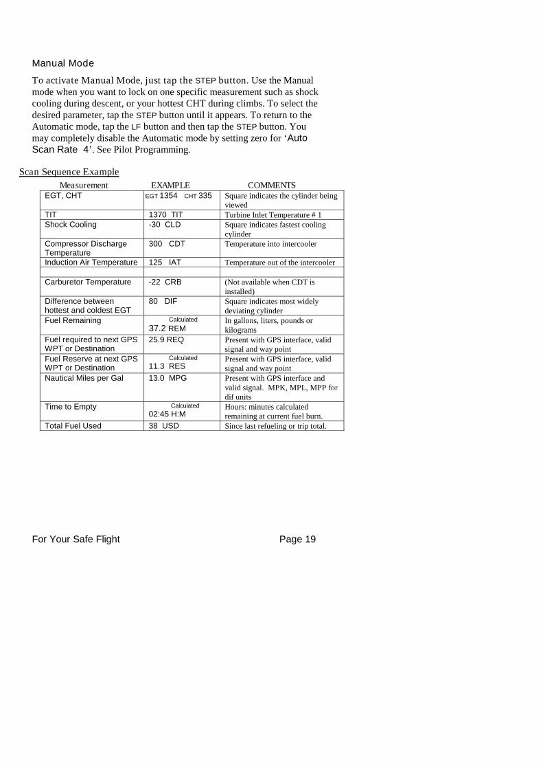
To activate Manual Mode, just tap the STEP button. Use the Manualmode when you want to lock on one specific measurement such as shockcooling during descent, or your hottest CHT during climbs. To select thedesired parameter, tap the STEP button until it appears. To return to theAutomatic mode, tap the LF button and then tap the STEP button. Youmay completely disable the Automatic mode by setting zero for ‘AutoScan Rate 4’. See Pilot Programming.
Scan Sequence Example
Measurement EXAMPLE COMMENTSEGT, CHT EGT 1354 CHT 335 Square indicates the cylinder being
viewedTIT 1370 TIT Turbine Inlet Temperature # 1Shock Cooling -30 CLD Square indicates fastest cooling
cylinderCompressor DischargeTemperature
300 CDT Temperature into intercooler
Induction Air Temperature 125 IAT Temperature out of the intercooler
Carburetor Temperature -22 CRB (Not available when CDT isinstalled)
Difference betweenhottest and coldest EGT
80 DIF Square indicates most widelydeviating cylinder
Fuel Remaining Calculated
37.2 REMIn gallons, liters, pounds orkilograms
Fuel required to next GPSWPT or Destination
25.9 REQ Present with GPS interface, validsignal and way point
Fuel Reserve at next GPSWPT or Destination
Calculated
11.3 RESPresent with GPS interface, validsignal and way point
Nautical Miles per Gal 13.0 MPG Present with GPS interface andvalid signal. MPK, MPL, MPP fordif units
Time to Empty Calculated
02:45 H:MHours: minutes calculatedremaining at current fuel burn.
Total Fuel Used 38 USD Since last refueling or trip total.
For Your Safe Flight Page 20
Section 5 - LeanFind
The EDM supports two methods of leaning; ROP (Rich Of Peak) andLOP (Lean Of Peak). Note: on power-up, the unit defaults toRich Of Peak mode, but is easily changed to Lean Of Peak mode. Duringtraditional Rich Of Peak leaning, you’ll finalize the mixture to about 20°to 80° rich of peak (depending on engine operating requirements).However, with the advent of closely balanced injectors (such as GAMI),it is possible to set the mixture lean of peak—thus saving fuel andrunning the engine cooler. Both Rich Of Peak and Lean Of Peakprocesses are described in detail in this manual.
Upon reaching cruise configuration, use the LeanFind mode to identifythe correct cylinder to reach peak EGT (for Rich Of Peak this is theFIRST to peak, for Lean Of Peak this is the LAST to peak). To changefrom one method to the other, right after activating LeanFind, holdSTEP and LF and the other method will be momentarily shown: ROP(Rich Of Peak) or LOP (Lean Of Peak). Release buttons after the othermethod appears.
For Your Safe Flight Page 21
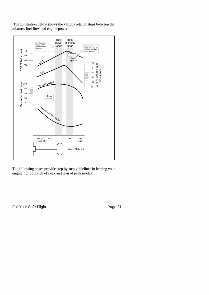
The illustration below shows the various relationships between themixture, fuel flow and engine power:
The following pages provide step by step guidelines in leaning yourengine, for both rich of peak and lean of peak modes:
EG
T°F
be
low
peak
Perc
en
to
fbe
stp
ow
er
CH
T°F
cha
ng
efr
om
best
pow
er
Besteconomy
range
Bestpowerrange
0
-200
-100
-300
-20
20
-60
-40
0
-80
100
85
90
95
80
EGT
CHT
Percent power
Specific fuel consumption
Overlean
LeanRichFull Rich(Take-off)
Leaner Mixture
PeakPower
First cylinderto peak. UseRich of Peakleaning
Last cylinder topeak. Use Lean ofPeak leaning withGAMI injectors
GAMIspread
For Your Safe Flight Page 22
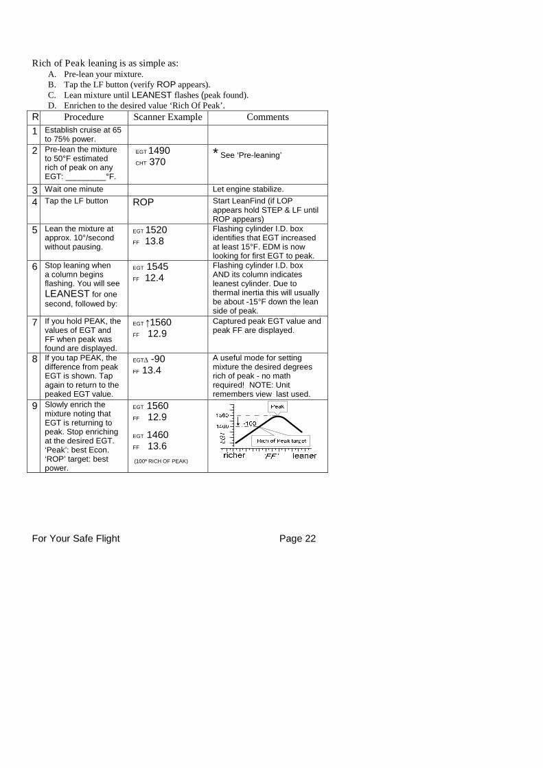
Rich of Peak leaning is as simple as:A. Pre-lean your mixture.B. Tap the LF button (verify ROP appears).C. Lean mixture until LEANEST flashes (peak found).D. Enrichen to the desired value ‘Rich Of Peak’.
R Procedure Scanner Example Comments
1 Establish cruise at 65to 75% power.
2 Pre-lean the mixtureto 50°F estimatedrich of peak on anyEGT: _________°F.
EGT 1490CHT 370
* See ‘Pre-leaning’
3 Wait one minute Let engine stabilize.
4 Tap the LF button ROP Start LeanFind (if LOPappears hold STEP & LF untilROP appears)
5 Lean the mixture atapprox. 10°/secondwithout pausing.
EGT 1520FF 13.8
Flashing cylinder I.D. boxidentifies that EGT increasedat least 15°F. EDM is nowlooking for first EGT to peak.
6 Stop leaning whena column beginsflashing. You will see
LEANEST for onesecond, followed by:
EGT 1545FF 12.4
Flashing cylinder I.D. boxAND its column indicatesleanest cylinder. Due tothermal inertia this will usuallybe about -15°F down the leanside of peak.
7 If you hold PEAK, thevalues of EGT andFF when peak wasfound are displayed.
EGT ↑1560FF 12.9
Captured peak EGT value andpeak FF are displayed.
8 If you tap PEAK, thedifference from peakEGT is shown. Tapagain to return to thepeaked EGT value.
EGT∆ -90FF 13.4
A useful mode for settingmixture the desired degreesrich of peak - no mathrequired! NOTE: Unitremembers view last used.
9 Slowly enrich themixture noting thatEGT is returning topeak. Stop enrichingat the desired EGT.‘Peak’: best Econ.‘ROP’ target: bestpower.
EGT 1560FF 12.9
EGT 1460FF 13.6
(100º RICH OF PEAK)
For Your Safe Flight Page 23
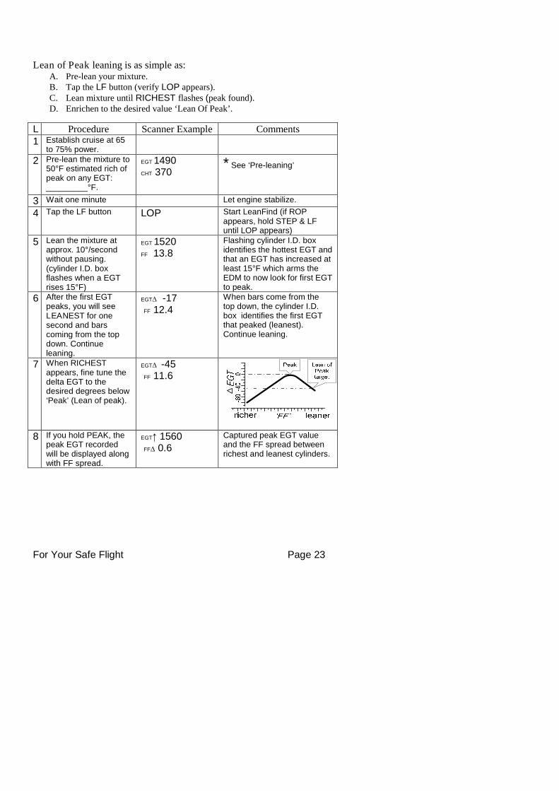
Lean of Peak leaning is as simple as:A. Pre-lean your mixture.B. Tap the LF button (verify LOP appears).C. Lean mixture until RICHEST flashes (peak found).D. Enrichen to the desired value ‘Lean Of Peak’.
L Procedure Scanner Example Comments1 Establish cruise at 65
to 75% power.
2 Pre-lean the mixture to50°F estimated rich ofpeak on any EGT:_________°F.
EGT 1490CHT 370
* See ‘Pre-leaning’
3 Wait one minute Let engine stabilize.
4 Tap the LF button LOP Start LeanFind (if ROPappears, hold STEP & LFuntil LOP appears)
5 Lean the mixture atapprox. 10°/secondwithout pausing.(cylinder I.D. boxflashes when a EGTrises 15°F)
EGT 1520FF 13.8
Flashing cylinder I.D. boxidentifies the hottest EGT andthat an EGT has increased atleast 15°F which arms theEDM to now look for first EGTto peak.
6 After the first EGTpeaks, you will seeLEANEST for onesecond and barscoming from the topdown. Continueleaning.
EGT∆ -17FF 12.4
When bars come from thetop down, the cylinder I.D.box identifies the first EGTthat peaked (leanest).Continue leaning.
7 When RICHESTappears, fine tune thedelta EGT to thedesired degrees below‘Peak’ (Lean of peak).
EGT∆ -45FF 11.6
8 If you hold PEAK, thepeak EGT recordedwill be displayed alongwith FF spread.
EGT↑ 1560FF∆ 0.6
Captured peak EGT valueand the FF spread betweenrichest and leanest cylinders.
For Your Safe Flight Page 24
LeanFind Procedure—General Explanation
Lycoming and Continental established specific restrictions onleaning that must be followed, such as percent power, climbleaning, and TIT limits. Lycoming recommends operation atpeak of EGT at 75% or less power only. Continentalrecommends operation at peak EGT at 65% or less poweronly. This guide does not supersede specificrecommendations of the engine or airframe manufacturer. It isyour responsibility to know your aircraft’s limitations.
Pre-leaning: The leaning process typically begins with ‘pre-leaning’ toinsure all cylinders are operating rich of peak EGT (note: you canoptionally activate ‘Normalize’ - hold LF until NRM appears - making iteasier to confirm all EGT’s decrease). Now enrichen the mixture toachieve a 50° drop on the hottest EGT. Insure that all EGT’s decrease.Wait one minute to allow temperatures to stabilize.
Lean Find-Initiation: The leaning process typically begins with ‘pre-leaning’ to insure all cylinders are operating rich of peak EGT. This isaccomplished as follows. As you lean the mixture watch the hottest EGTand note when it begins to decrease in temperature. Now enrichen themixture to achieve a 50° drop on the hottest EGT. Insure that all EGT’sdecrease. Wait one minute to allow temperatures to stabilize. Note:When the first EGT peaks, you can optionally activate ‘Normalize’ -hold LF until NRM appears - making it easier to confirm that all EGT’sdecrease.
Lean Find-Initiation: Initiate the EDM leaning mode by tapping the LF
button. Note that the EDM displays its current leaning modemomentarily: ‘ROP’ for operating Rich of Peak or ‘LOP’ for operatingLean of Peak. To change, simply hold STEP and LF until the displayshows the other mode. The EDM is now waiting for a 15° rise on anyEGT (this feature significantly reduces false peaks). Lean the mixturewithout pausing to achieve about a 10 deg per second change. With thevernier mixture control, turn the knob about a quarter turn every second.With the non-vernier or quadrant mixture control, lean slowly andsmoothly about 1/16 inch every five seconds (note: leaning accuratelywith a quadrant system is difficult due to its mechanical linkage).

For Your Safe Flight Page 25
Lean Find-Activation: When a 15° EGT rise occurs, LeanFindactivates (indicated by a cylinder I.D. box flashing over the number ofthe hottest EGT). Remember: The LeanFind mode is not active untila cylinder I.D. box is flashing. To show the progress of the leaningprocess, the EDM now displays the hottest EGT in the left side of thedigital display and the fuel flow in the right side. This informationallows you to observe the EGT behavior throughout the leaning process.
For Your Safe Flight Page 26
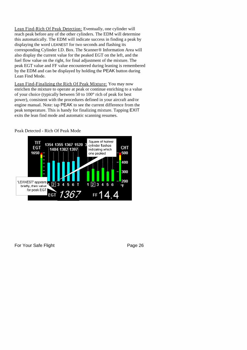
Lean Find-Rich Of Peak Detection: Eventually, one cylinder willreach peak before any of the other cylinders. The EDM will determinethis automatically. The EDM will indicate success in finding a peak bydisplaying the word LEANEST for two seconds and flashing itscorresponding Cylinder I.D. Box. The Scanner® Information Area willalso display the current value for the peaked EGT on the left, and thefuel flow value on the right, for final adjustment of the mixture. Thepeak EGT value and FF value encountered during leaning is rememberedby the EDM and can be displayed by holding the PEAK button duringLean Find Mode.
Lean Find-Finalizing the Rich Of Peak Mixture: You may nowenrichen the mixture to operate at peak or continue enriching to a valueof your choice (typically between 50 to 100° rich of peak for bestpower), consistent with the procedures defined in your aircraft and/orengine manual. Note: tap PEAK to see the current difference from thepeak temperature. This is handy for finalizing mixture. Tapping EXITexits the lean find mode and automatic scanning resumes.
Peak Detected - Rich Of Peak Mode
For Your Safe Flight Page 27
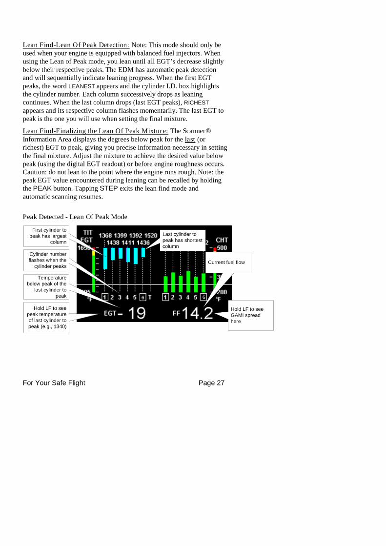
Lean Find-Lean Of Peak Detection: Note: This mode should only beused when your engine is equipped with balanced fuel injectors. Whenusing the Lean of Peak mode, you lean until all EGT’s decrease slightlybelow their respective peaks. The EDM has automatic peak detectionand will sequentially indicate leaning progress. When the first EGTpeaks, the word LEANEST appears and the cylinder I.D. box highlightsthe cylinder number. Each column successively drops as leaningcontinues. When the last column drops (last EGT peaks), RICHEST
appears and its respective column flashes momentarily. The last EGT topeak is the one you will use when setting the final mixture.
Lean Find-Finalizing the Lean Of Peak Mixture: The Scanner®Information Area displays the degrees below peak for the last (orrichest) EGT to peak, giving you precise information necessary in settingthe final mixture. Adjust the mixture to achieve the desired value belowpeak (using the digital EGT readout) or before engine roughness occurs.Caution: do not lean to the point where the engine runs rough. Note: thepeak EGT value encountered during leaning can be recalled by holdingthe PEAK button. Tapping STEP exits the lean find mode andautomatic scanning resumes.
Peak Detected - Lean Of Peak Mode
Cylinder numberflashes when the
cylinder peaks
Temperaturebelow peak of the
last cylinder topeak
Hold LF to seepeak temperatureof last cylinder topeak (e.g., 1340)
Hold LF to seeGAMI spreadhere
First cylinder topeak has largest
column
Last cylinder topeak has shortestcolumn
Current fuel flow
6 6
For Your Safe Flight Page 28
Expanded Leaning Procedures
Lean Of Peak mode: During the ‘lean of peak’ process, the EDM huntsfor the last cylinder to peak. Ultimately, you want to have ALL cylindersoperating on the lean side of peak. You will final adjust your mixture tothis cylinder. To provide a unique graphical depiction during lean ofpeak operation, the columns become inverted after the first EGT goesjust beyond peak. Each EGT column then originates from the top of thedisplay and drops downward. As each subsequent EGT goes past peak,its column will begin falling. The columns length depicts how far theEGT has dropped below its original peak. In this mode, each segment is5° F. You will continue to lean until the last EGT peaks note: never leanto the point where the engine is running rough). When the last EGTpeaks, its column will flash and RICHEST appears. The digital readoutwill show the current temperature difference from where peak EGToccurred and the current fuel flow (if so equipped). Note: holding thePEAK button will show the captured peak value of the ‘last EGT topeak’ and also the difference in fuel flow between the first and last topeak (known as the GAMI Spread). This is a good indication of injectorbalance (the smaller the FF difference, the better the balance). TappingSTEP exits the lean find mode and automatic scanning resumes.
Leaning Turbocharged Engines: The leaning process forturbocharged engines is by reference to the first EGT or TIT to reachpeak. Therefore you should use the Rich Of Peak mode. The factoryTIT red line (typically 1650°F to 1750°F) may limit the leaningprocess, depending on flight conditions. If TIT exceeds red line (butnot by more than 99°), the EDM will allow you to continue leaning forone minute before a TIT alarm activates. NOTE: TIT can readapproximately 100°F hotter than the hottest EGT due to unburned fuelin the exhaust igniting and is not necessarily abnormal behavior. Thereduced size of the JPI Hastaloy-X-tip probes produce faster response
and are more accurate than the massive factory installed probes.Therefore a JPI probe may read as much as 100°F higher than the
factory installed probe. However, the certified factory-installed gaugemust be obeyed as the limiting factor when adjusting your engine.
For Your Safe Flight Page 29
Section 6 - Fuel Flow Operation
Fuel Management
Without a means of measuring accurate fuel flow, you must rely on theaircraft fuel gauges or total time of flight. Aircraft fuel gauges arenotoriously inaccurate (they are only required by the FAA to readaccurately when displaying empty). Determining fuel consumption bymultiplying time of flight by estimated flow rate is, at best, anapproximation, and assumes a constant fuel flow rate for each phase offlight. However, the EDM Fuel Flow Option uses a small, turbinetransducer that measures the fuel flowing into the engine. Higher fuelflow causes the transducer turbine to rotate faster which generates afaster pulse rate. Because the transducer turbine generates thousands ofpulses per gallon of fuel, it can measure with high resolution the amountof fuel that flows into the engine. Prior to engine start you inform theEDM Fuel Flow Computer system of the known quantity of fuelonboard, it then subsequently tracks all fuel delivered to the engine.
IMPORTANT !For EDM fuel calculations to be accurate, it is
mandatory that you inform the EDM of the correctamount of usable fuel onboard the aircraft and confirmproper operation of the fuel flow transducer prior to andduring flight. Do not rely on fuel flow instruments todetermine fuel levels in tanks. Refer to original fuel flowinstrumentation for primary fuel managementinformation.
For Your Safe Flight Page 30
Start Up Fuel
On power-up, you will be prompted to enter any fuel you might haveadded to the aircraft (this process updates the REM and USD values).The EDM will flash REFUEL? . If you didn’t add any fuel, simply tapEXIT to quit, otherwise tap NEXT to pick one of the three quickset choicesbelow:
Choice 1) MAIN 66.0 GAL : Tap SAVE to accept or NEXT for choice#2. This shortcut sets REM to the MAIN tank value (66 inthis case) you set up in your fuel computer.
Choice 2) MAIN + AUX 82.0 GAL : Tap SAVE to accept or NEXT forchoice #3. This shortcut sets REM to the sum of MAIN andAUX you set up in your fuel computer.
Choice 3) Adjust? + 0.0 GAL : Tap either ADD or REMOVE to adjustREM. Use when adding a partial amount of fuel. Tap SAVE
to accept adjustment or NEXT to repeat REFUEL?.
NOTE: If you forgot to perform your EDM REFUEL before startingthe engine, it can still be performed. The EDM will automaticallysubtract any burned fuel from the value you choose (not applicable tothe ‘Adjust? + 0.0’ feature)
You are responsible for insuring that your usage of the REFUELfeature results in the EDM’s REM parameter showing the correctamount of usable fuel remaining onboard the aircraft.
The three examples, shown below, depict different aircraft tankconfigurations and how you can update your EDM after refueling youraircraft. These are meant to be general guidelines.
For Your Safe Flight Page 31
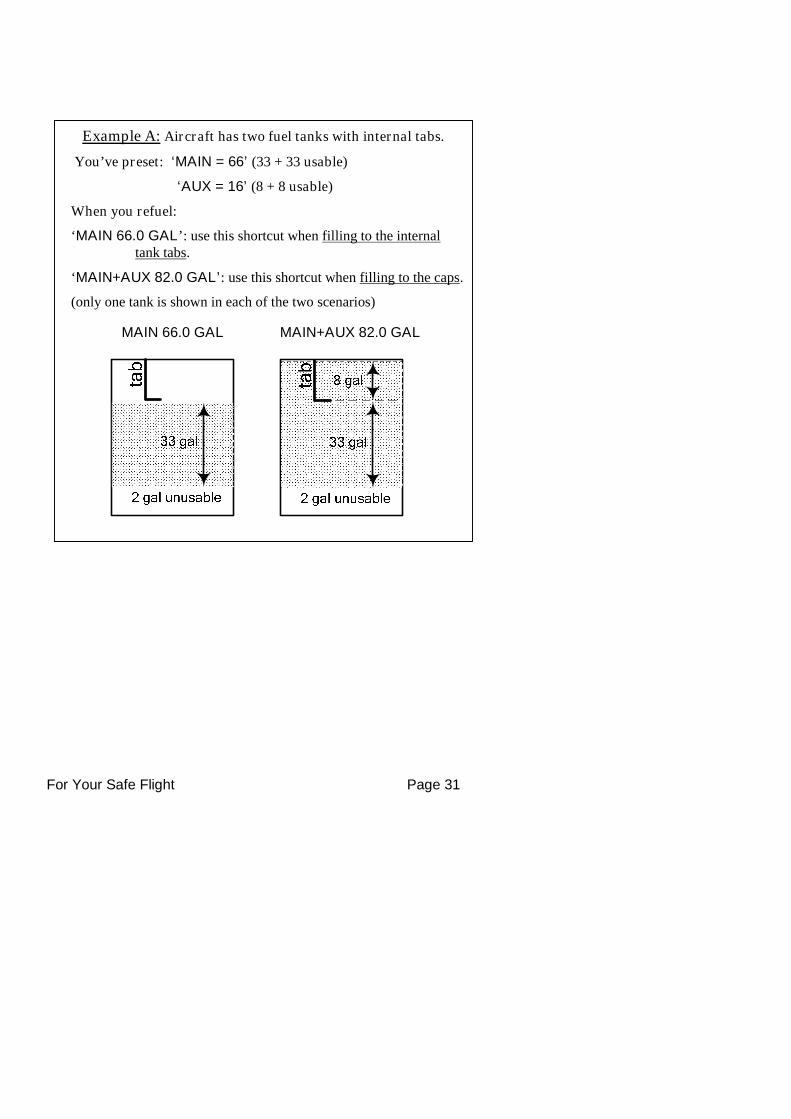
Example A: Aircraft has two fuel tanks with internal tabs.
You’ve preset: ‘MAIN = 66’ (33 + 33 usable)
‘AUX = 16’ (8 + 8 usable)
When you refuel:
‘MAIN 66.0 GAL’: use this shortcut when filling to the internaltank tabs.
‘MAIN+AUX 82.0 GAL’: use this shortcut when filling to the caps.
(only one tank is shown in each of the two scenarios)
MAIN+AUX 82.0 GALMAIN 66.0 GAL
For Your Safe Flight Page 32
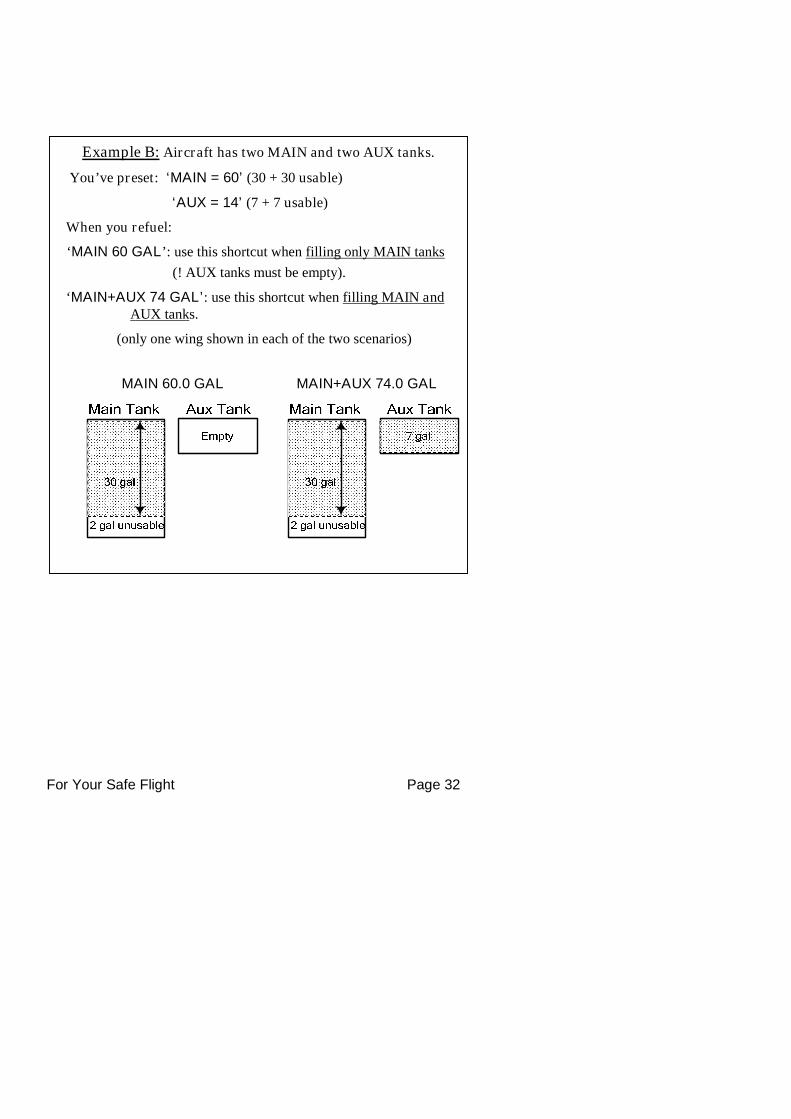
Example B: Aircraft has two MAIN and two AUX tanks.
You’ve preset: ‘MAIN = 60’ (30 + 30 usable)
‘AUX = 14’ (7 + 7 usable)
When you refuel:
‘MAIN 60 GAL’: use this shortcut when filling only MAIN tanks
(! AUX tanks must be empty).
‘MAIN+AUX 74 GAL’: use this shortcut when filling MAIN andAUX tanks.
(only one wing shown in each of the two scenarios)
MAIN+AUX 74.0 GALMAIN 60.0 GAL
For Your Safe Flight Page 33
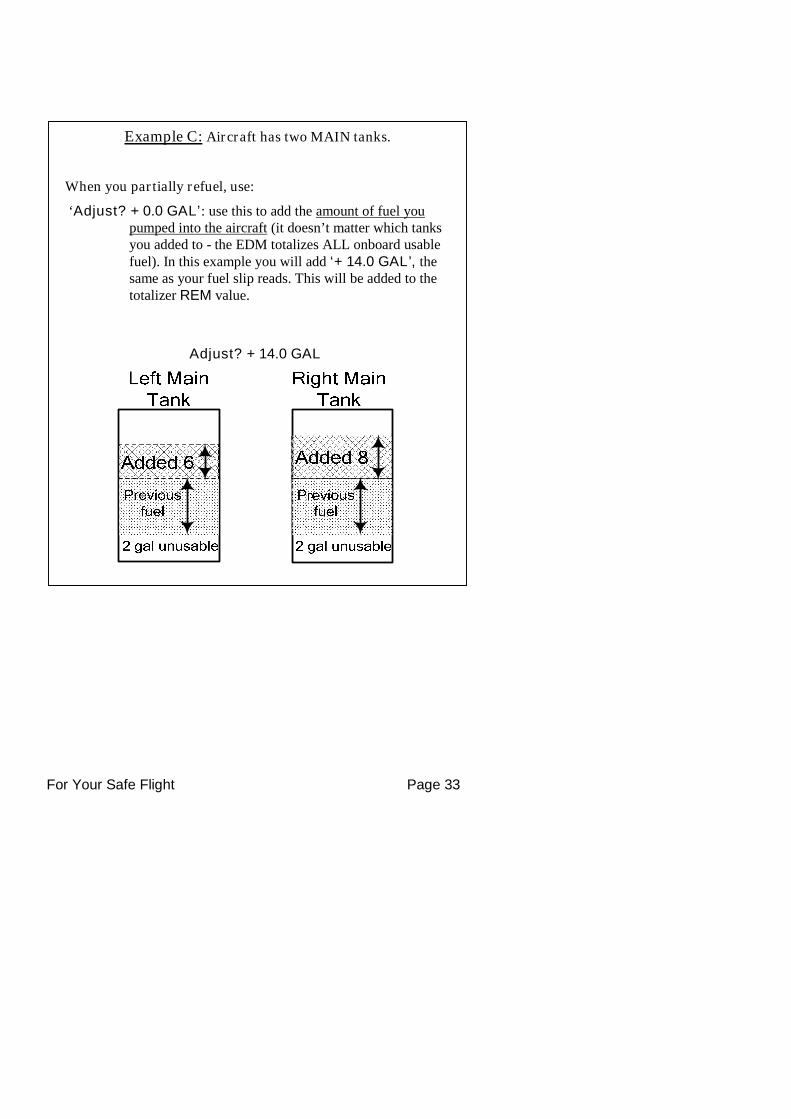
Example C: Aircraft has two MAIN tanks.
When you partially refuel, use:
‘Adjust? + 0.0 GAL’: use this to add the amount of fuel youpumped into the aircraft (it doesn’t matter which tanksyou added to - the EDM totalizes ALL onboard usablefuel). In this example you will add ‘+ 14.0 GAL’, thesame as your fuel slip reads. This will be added to thetotalizer REM value.
Adjust? + 14.0 GAL
For Your Safe Flight Page 34
Resetting ‘USD’
USD is automatically reset whenever you perform REFUEL on yourEDM (except if TRIP mode = yes).
After filling your tanks and prior to engine start you should inform theEDM that the aircraft has been filled. In this case USD is automaticallyset to zero.
If you forgot and have already started the engine, and then you informthe EDM that tanks have been filled, then some fuel has already beenused. Not to worry as the EDM will automatically set USD to thisamount and also subtract it from the REM value, keeping the two valuesin balance.
To manually zero the amount of fuel USD at any time, manuallySTEP to display USD and then hold both DIM (button 3) and EGT/FF(button 4) until the display shows ‘.0 USD’ (this normally takes aboutfive seconds).
Trip Mode (Accumulate Trip Totalizer)
Trip mode is typically used if you want to track the total fuel used over amulti-stop cross country. To have the USD parameter continuouslyaccumulate total consumed fuel, set TRIP? Y. ‘Trip Mode’ is describedin the ‘Program Mode section’. Note: typically, TRIP? is set to ‘N’ sothat USD will be reset every time you fuel the aircraft.
Scanner Fuel Flow Display Select
Button four selects three different Scanner filters - ALL, EGT or FF.Tapping this button will select the next choice (shown after the ‘/’symbol):
ALL/EGT: all installed parameters are shown in Scanner.
EGT/FF: only the installed temperature (and battery voltage)parameters are shown in Scanner.
FF/ALL: only fuel flow parameters are shown in Scanner.
Note: Scanner filter or mode selection does not affect Alarms or analogdisplays.
For Your Safe Flight Page 35
Section 7 - Alarms
Whenever a measured parameter falls outside of the normal allowedoperating limits, i.e. goes beyond redline, the main display will blink analert icon. This consists of the current digital value and a flashing redlabel in the Scanner area and the RAD. For example, if CHT 2 is at 480,and redline is 460, the alert would be displayed as 480 HI CHT2. Otheralarm examples are:
2780 HI RPM, 15 LO OIL-PSI, 240 HI OIL-TEMP.
Tapping the CLEAR button extinguishes the alert for ten minuteswhereas holding the CLEAR button turns the alarm off for the remainderof the flight.
Primary alarm limits for each specific aircraft model are set by JPIin accordance with the Pilot Operating Handbook and/or TCDS andare not programmable by the pilot. These typically include some or allof the following measurements: CHT, CDT, O-T, O-P, F-P, GAL LEFT,GAL RIGHT, MAP, RPM, FF, IAT, CRB, and TIT. To view the alarmlimits screen, hold button 2 during power up (or hold both buttons 2 & 3during normal operation), tap NEXT until the list is displayed.
The primary functions for your installation are shown on the Primarylabel on the back of the instrument and are identical to those specified inthe FAA Approved Airplane Flight Manual/Pilot’s Operating Handbook.
Non-primary Alarm Priority
Primary alarms will always have precedence over non-primary alarms.The typical non-primary alarm priorities are as follows:
Highest ...........................................................................................Lowest
MIN REM DIF CLD BUS H BUS L AMP
For Your Safe Flight Page 36
Section 8 - Memory and Data Download
The EDM compresses and records all displayed parameters once everysix seconds (default) in Long Term Data Memory (note: you can changethis rate to be 2 to 500 seconds). This data is retrievable by inserting aUSB Drive into the jack on the front of the instrument and following theprompts. You can choose to retrieve ‘ALL’ the data stored in the EDM,or only the ‘NEW’ data recorded since your last retrieval. In either case,the selected data in the EDM is not erased. The data can later be viewedon EZTrends, a PC program available from JPI or over the internet.
Recording typically begins when EGTs are greater than 500°F or RPM isgreater than 500. The amount of data that the EDM can store will varydepending on how rapidly parameters change. The typical storagecapacity is greater than 100 hours at a 6 second recording interval, butcan vary depending on configuration. When the memory becomes full,the oldest data will be discarded to make room for the newest. All dataare time-stamped. The EDM contains a real-time clock that may be setwhen you initially program your instrument. You may change therecording interval from 2 to 500 seconds, even in flight (when youchange the interval in flight, the current flight file is closed and a newflight file is started at the new interval).
For Your Safe Flight Page 37
Downloading Data from the EDM
Downloading is a simple process. Follow the steps below:
a. With the EDM powered up, plug the USB flash drive into theEDM USB port.
b. Wait for the EDM display to show DOWNLOAD: NEW.
c. To download only the new data since the last download, tap theSTEP button.
d. To download all data in the EDM, tap the CHANGE button tosee DOWNLOAD: ALL, then tap STEP.
e. You will see a ‘progress indicator’ as the data is copied to theUSB flash drive. DO NOT INTERRUPT THIS PROCESS.When the download is complete the display on the EDM willshow DONE and then return to normal operation.
f. Wait until the process is complete then remove the USB flashdrive from the USB connector.
Transferring data from the USB Flash Drive to a PC
To transfer your data from the USB flash drive to your PC, followthese easy steps.
1. On your PC, start the EzTrends program.
2. Plug in the USB flash drive into an available USB port.
3. In EzTrends, select the Move and Plot Data from Memory Stickoption.
4. In the displayed list, find the USB flash drive and double click it.
5. Select the file you wish to plot and then select the flight in that file.
Refer to the EzTrends manual for details on how to use EzTrends.
For Your Safe Flight Page 38
Section 9 - First Time Setup and Customization
Your EDM comes with most settings programmed. However somesettings you will fine tune to your installation and/or preferences.We recommend you perform the following minimum set up:
1. Pilot Programming Mode: Set the GPS Communications format to match your type of GPS.
Fine tuning of fuel flow K-factor is important as it affects yourfuel computer parameter accuracies.
Set the Engine HP equal to your engines rated horsepower.
Perform the HP Constant set up for best accuracy of the PercentHorsepower readout.
Optionally fine tune other parameters such as MAP, OAT.
2. EDM Screen CustomizationUse ‘EDM Config’ to customize your EDM. All EDM930 andEDM960 units manufactured or updated after Sep 15, 2012 havethe EDM Configuration Editor built into a separate utility memoryarea of the EDM.
To start the EDM Configuration Editor, hold the left two EDMbuttons (STEP & LF) while powering up the EDM. This will startthe EDM in a special AppLoader mode. Once the EDMConfiguration Editor program is found, a button will be labeledCFG EDITOR. Press the button to run the EDM ConfigurationEditor program.
When EDM Configuration Editor starts, it will show a startupscreen titled EDM960 Configuration Editor or EDM930Configuration Editor that lists the version information for theEditor.
3. Fuel Level Calibration Fuel Level calibration must be performed before the fuel level
feature will function.
Collect your calibration data for various fuel tank levels (calledpoints) by putting the EDM into the ‘Fuel Level Readings’mode. Carefully review readings during the process to insure the

For Your Safe Flight Page 39
calibration data is sensible, correct and useable. Note: Pleaserefer to the installation manual for accessing fuel tables andcalibration on page 22 item 24.4.
Enter the data by putting the EDM into ‘Fuel Table Data’ modeand enter your values into each tanks chart.
For Your Safe Flight Page 40
Pilot Programming Mode
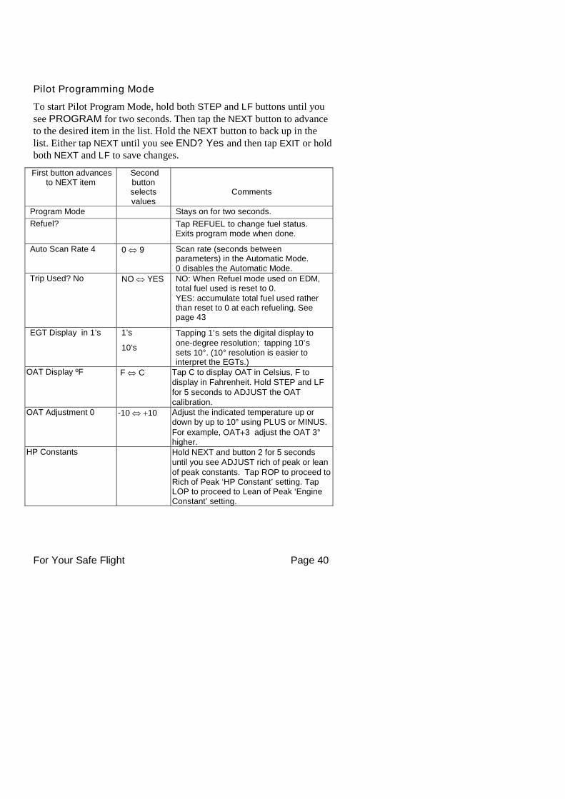
To start Pilot Program Mode, hold both STEP and LF buttons until yousee PROGRAM for two seconds. Then tap the NEXT button to advanceto the desired item in the list. Hold the NEXT button to back up in thelist. Either tap NEXT until you see END? Yes and then tap EXIT or holdboth NEXT and LF to save changes.
First button advancesto NEXT item
Secondbuttonselectsvalues
Comments
Program Mode Stays on for two seconds.
Refuel? Tap REFUEL to change fuel status.Exits program mode when done.
Auto Scan Rate 4 0 9 Scan rate (seconds betweenparameters) in the Automatic Mode.0 disables the Automatic Mode.
Trip Used? No NO YES NO: When Refuel mode used on EDM,total fuel used is reset to 0.YES: accumulate total fuel used ratherthan reset to 0 at each refueling. Seepage 43
EGT Display in 1’s 1’s
10’s
Tapping 1’s sets the digital display toone-degree resolution; tapping 10’ssets 10°. (10° resolution is easier tointerpret the EGTs.)
OAT Display ºF F C Tap C to display OAT in Celsius, F todisplay in Fahrenheit. Hold STEP and LFfor 5 seconds to ADJUST the OATcalibration.
OAT Adjustment 0 -10 10 Adjust the indicated temperature up ordown by up to 10° using PLUS or MINUS.For example, OAT3 adjust the OAT 3°higher.
HP Constants Hold NEXT and button 2 for 5 secondsuntil you see ADJUST rich of peak or leanof peak constants. Tap ROP to proceed toRich of Peak ‘HP Constant’ setting. TapLOP to proceed to Lean of Peak ‘EngineConstant’ setting.
For Your Safe Flight Page 41
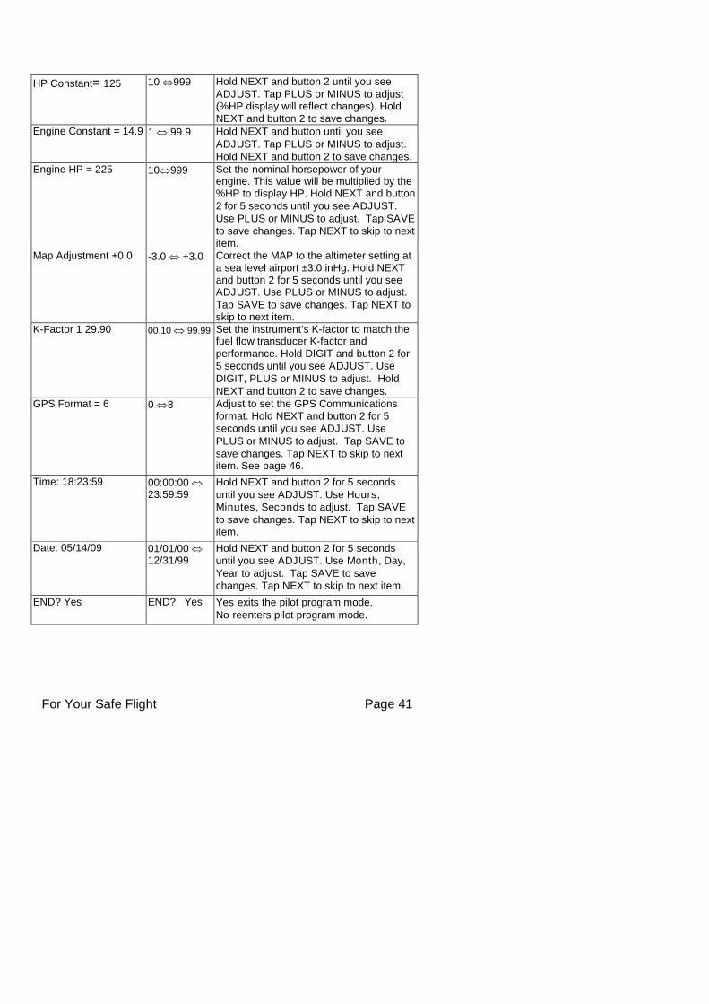
HP Constant= 125 10 999 Hold NEXT and button 2 until you seeADJUST. Tap PLUS or MINUS to adjust(%HP display will reflect changes). HoldNEXT and button 2 to save changes.
Engine Constant = 14.9 1 99.9 Hold NEXT and button until you seeADJUST. Tap PLUS or MINUS to adjust.Hold NEXT and button 2 to save changes.
Engine HP = 225 10999 Set the nominal horsepower of yourengine. This value will be multiplied by the%HP to display HP. Hold NEXT and button2 for 5 seconds until you see ADJUST.Use PLUS or MINUS to adjust. Tap SAVEto save changes. Tap NEXT to skip to nextitem.
Map Adjustment +0.0 -3.0 +3.0 Correct the MAP to the altimeter setting ata sea level airport ±3.0 inHg. Hold NEXTand button 2 for 5 seconds until you seeADJUST. Use PLUS or MINUS to adjust.Tap SAVE to save changes. Tap NEXT toskip to next item.
K-Factor 1 29.90 00.10 99.99 Set the instrument’s K-factor to match thefuel flow transducer K-factor andperformance. Hold DIGIT and button 2 for5 seconds until you see ADJUST. UseDIGIT, PLUS or MINUS to adjust. HoldNEXT and button 2 to save changes.
GPS Format = 6 0 8 Adjust to set the GPS Communicationsformat. Hold NEXT and button 2 for 5seconds until you see ADJUST. UsePLUS or MINUS to adjust. Tap SAVE tosave changes. Tap NEXT to skip to nextitem. See page 46.
Time: 18:23:59 00:00:00 23:59:59
Hold NEXT and button 2 for 5 secondsuntil you see ADJUST. Use Hours,Minutes, Seconds to adjust. Tap SAVEto save changes. Tap NEXT to skip to nextitem.
Date: 05/14/09 01/01/00 12/31/99
Hold NEXT and button 2 for 5 secondsuntil you see ADJUST. Use Month, Day,Year to adjust. Tap SAVE to savechanges. Tap NEXT to skip to next item.
END? Yes END? Yes Yes exits the pilot program mode.No reenters pilot program mode.
For Your Safe Flight Page 42
Adjusting the HP Constant for Rich of Peak Operation
To fine tune the %HP readout, follow this procedure airborne between5,000 and 8,000 feet MSL.
1. Enter the pilot program mode by simultaneously holding the STEP
and LF buttons for five seconds.
2. Tap STEP repeatedly until you see HP Constants. Hold both NEXT
and Button 2 until you see ROP and LOP appear in status bar. TapROP. Now HP Constant 125 should appear. Hold both NEXT andButton 2 until you see ADJUST momentarily. Adjustment range forthe HP Constant is 50 to 300.
3. Set the MP and RPM per your POH to 70 percent power. Letconditions stabilize.
4. Adjust the HP Constant value PLUS or MINUS so that the %HP
reading on the display equals ‘70 %HP’. Note: this is the percent ofmaximum horsepower.
5. Hold both NEXT and Button 2 until you see SET.
Adjusting the MAP
This procedure allows you to adjust the MAP to the altimeter setting at asea level airport. NOTE: If airport is not at sea level, use thecorrection table to derive corrected sea level altimeter setting).
1. Enter the pilot program mode by simultaneously holding the STEP
and LF buttons for five seconds.
2. Tap NEXT repeatedly until you see MAP ADJUSTMENT +0.0.Then hold both the NEXT and Button 2 until you see ADJUSTmomentarily.
3. Adjust the value using the PLUS or MINUS until the value equals thealtimeter setting (sea level airport). The adjustment range for theMAP is ±3.0 inHg.
4. Hold both NEXT and Button 2 until you see SET.
For Your Safe Flight Page 43
Adjusting the HP Value
You must set the nominal horsepower of your engine. This value is usedto calculate the percent horsepower display.
1. Enter the pilot program mode by simultaneously holding the STEP
and LF buttons for five seconds.
2. Tap NEXT repeatedly until you see Engine HP 200. Then hold boththe NEXT and Button 2 until you see ADJUST momentarily.
3. Adjust the value PLUS or MINUS to equal your engines HP.
4. Hold both NEXT and Button 2 until you see SET.
Fuel Flow K factor
The K factor is shown on the fuel flow transducer as a hand written four-digit number, which represents the number of pulses per tenth gallon offuel flow. Before installing the transducer, record its K factor here_________. The EDM stores the K Factor in the form 29.12, i.e. if thetransducer K factor is 2912, you would enter 29.12 in the EDM’sK factor field.
Fine Tuning the K factorThe K factor shown on the fuel flow transducer does not take intoaccount your aircraft’s particular installation. Fuel hose diameters andlengths, elbows, fittings and routing can cause the true K factor to bedifferent from that shown on the fuel flow transducer. Fine tuning isaccomplished over multiple flights of sufficient duration and repeatableconditions. Use the process below to calculate and correct the K Factorto achieve maximum performance. Note: This process adjusts the Kfactor only half of the correction. We recommend this because itminimizes ‘chasing’ a correction target back and forth.
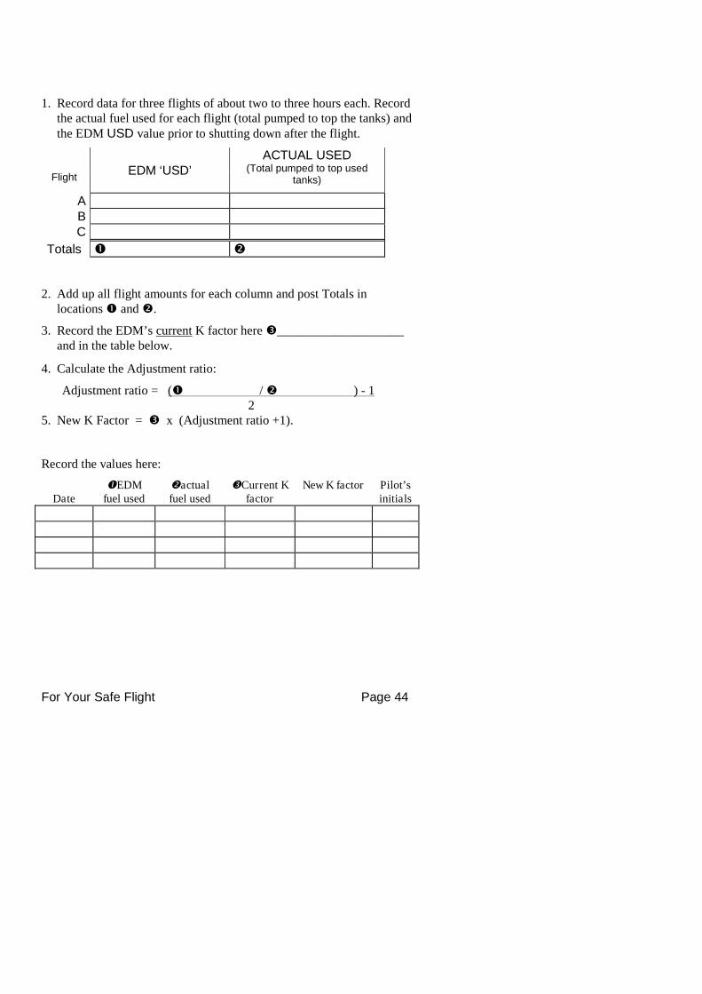
For Your Safe Flight Page 44
1. Record data for three flights of about two to three hours each. Recordthe actual fuel used for each flight (total pumped to top the tanks) andthe EDM USD value prior to shutting down after the flight.
FlightEDM ‘USD’
ACTUAL USED(Total pumped to top used
tanks)
ABC
Totals
2. Add up all flight amounts for each column and post Totals inlocations and.
3. Record the EDM’s current K factor here____________________and in the table below.
4. Calculate the Adjustment ratio:
Adjustment ratio = ( / ) - 12
5. New K Factor = x (Adjustment ratio +1).
Record the values here:
DateEDM
fuel usedactualfuel used
Current Kfactor
New K factor Pilot’sinitials
For Your Safe Flight Page 45
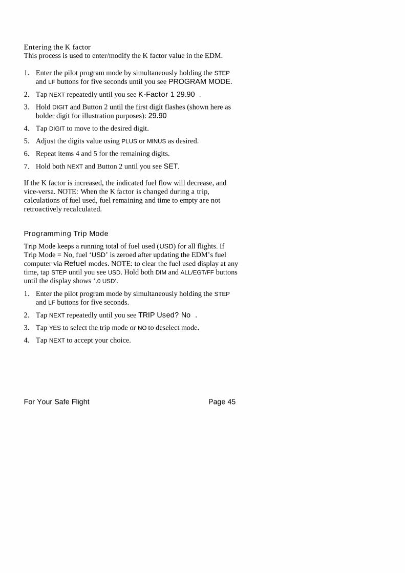
Entering the K factorThis process is used to enter/modify the K factor value in the EDM.
1. Enter the pilot program mode by simultaneously holding the STEP
and LF buttons for five seconds until you see PROGRAM MODE.
2. Tap NEXT repeatedly until you see K-Factor 1 29.90 .
3. Hold DIGIT and Button 2 until the first digit flashes (shown here asbolder digit for illustration purposes): 29.90
4. Tap DIGIT to move to the desired digit.
5. Adjust the digits value using PLUS or MINUS as desired.
6. Repeat items 4 and 5 for the remaining digits.
7. Hold both NEXT and Button 2 until you see SET.
If the K factor is increased, the indicated fuel flow will decrease, andvice-versa. NOTE: When the K factor is changed during a trip,calculations of fuel used, fuel remaining and time to empty are notretroactively recalculated.
Programming Trip Mode
Trip Mode keeps a running total of fuel used (USD) for all flights. IfTrip Mode = No, fuel ‘USD’ is zeroed after updating the EDM’s fuelcomputer via Refuel modes. NOTE: to clear the fuel used display at anytime, tap STEP until you see USD. Hold both DIM and ALL/EGT/FF buttonsuntil the display shows ‘.0 USD’.
1. Enter the pilot program mode by simultaneously holding the STEP
and LF buttons for five seconds.
2. Tap NEXT repeatedly until you see TRIP Used? No .
3. Tap YES to select the trip mode or NO to deselect mode.
4. Tap NEXT to accept your choice.
For Your Safe Flight Page 46
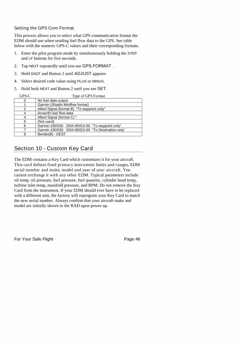
Setting the GPS Com Format
This process allows you to select what GPS communication format theEDM should use when sending fuel flow data to the GPS. See tablebelow with the numeric GPS-C values and their corresponding formats.
1. Enter the pilot program mode by simultaneously holding the STEP
and LF buttons for five seconds.
2. Tap NEXT repeatedly until you see GPS FORMAT .
3. Hold DIGIT and Button 2 until ADJUST appears
4. Select desired code value using PLUS or MINUS.
5. Hold both NEXT and Button 2 until you see SET.
GPS-C Type of GPS Format0 No fuel data output1 Garmin (Shadin Miniflow format)2 Allied Signal (format B) “To waypoint only”4 Arnav/EI fuel flow data4 Allied Signal (format C) *5 (Not used)6 Garmin 430/530 GNX-80/GX-60 “To waypoint only”7 Garmin 430/530 GNX-80/GX-60 “To Destination only”8 Bendix(B) - DEST
Section 10 - Custom Key Card
The EDM contains a Key Card which customizes it for your aircraft.This card defines fixed primary instrument limits and ranges, EDMserial number and make, model and year of your aircraft. Youcannot exchange it with any other EDM. Typical parameters include:oil temp, oil pressure, fuel pressure, fuel quantity, cylinder head temp,turbine inlet temp, manifold pressure, and RPM. Do not remove the KeyCard from the instrument. If your EDM should ever have to be replacedwith a different unit, the factory will reprogram your Key Card to matchthe new serial number. Always confirm that your aircraft make andmodel are initially shown in the RAD upon power up.
For Your Safe Flight Page 47
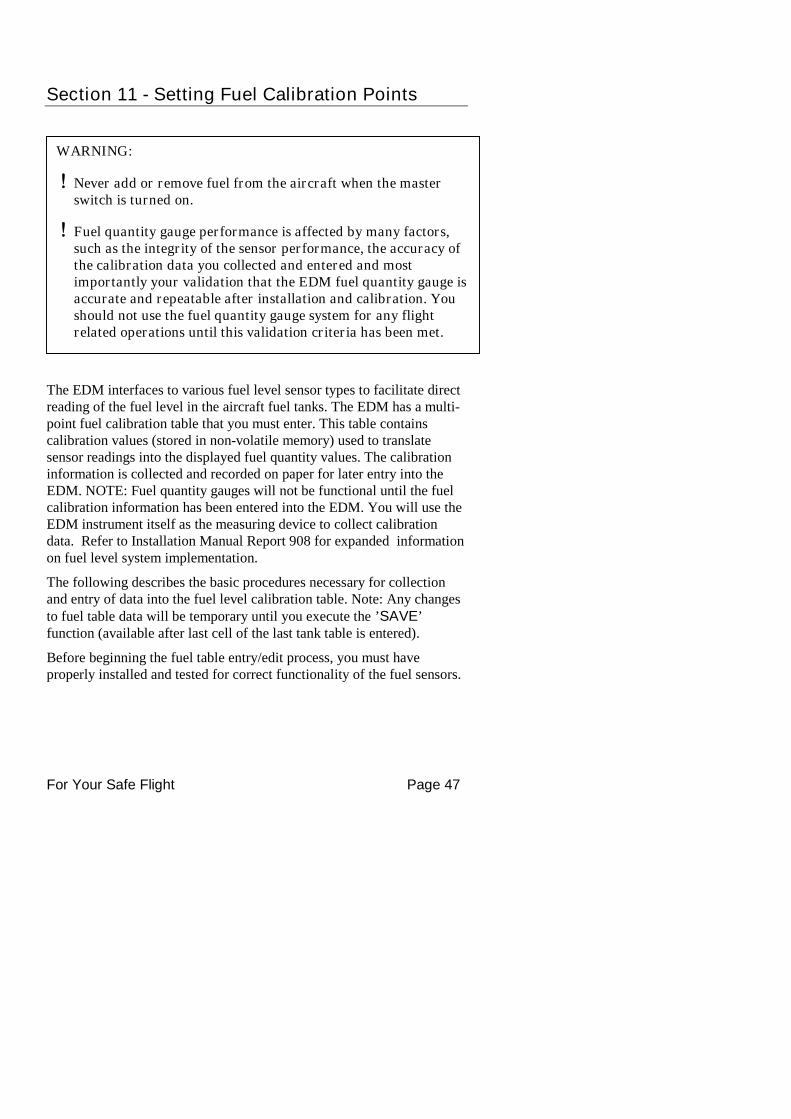
WARNING:
Never add or remove fuel from the aircraft when the masterswitch is turned on.
Fuel quantity gauge performance is affected by many factors,such as the integrity of the sensor performance, the accuracy ofthe calibration data you collected and entered and mostimportantly your validation that the EDM fuel quantity gauge isaccurate and repeatable after installation and calibration. Youshould not use the fuel quantity gauge system for any flightrelated operations until this validation criteria has been met.
Section 11 - Setting Fuel Calibration Points
The EDM interfaces to various fuel level sensor types to facilitate directreading of the fuel level in the aircraft fuel tanks. The EDM has a multi-point fuel calibration table that you must enter. This table containscalibration values (stored in non-volatile memory) used to translatesensor readings into the displayed fuel quantity values. The calibrationinformation is collected and recorded on paper for later entry into theEDM. NOTE: Fuel quantity gauges will not be functional until the fuelcalibration information has been entered into the EDM. You will use theEDM instrument itself as the measuring device to collect calibrationdata. Refer to Installation Manual Report 908 for expanded informationon fuel level system implementation.
The following describes the basic procedures necessary for collectionand entry of data into the fuel level calibration table. Note: Any changesto fuel table data will be temporary until you execute the ’SAVE’function (available after last cell of the last tank table is entered).
Before beginning the fuel table entry/edit process, you must haveproperly installed and tested for correct functionality of the fuel sensors.
For Your Safe Flight Page 48
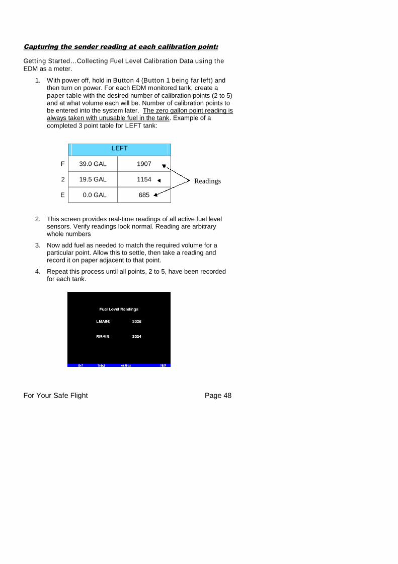
Capturing the sender reading at each calibration point:
Getting Started…Collecting Fuel Level Calibration Data using theEDM as a meter.
1. With power off, hold in Button 4 (Button 1 being far left) andthen turn on power. For each EDM monitored tank, create apaper table with the desired number of calibration points (2 to 5)and at what volume each will be. Number of calibration points tobe entered into the system later. The zero gallon point reading isalways taken with unusable fuel in the tank. Example of acompleted 3 point table for LEFT tank:
LEFT
F 39.0 GAL 1907
2 19.5 GAL 1154
E 0.0 GAL 685
2. This screen provides real-time readings of all active fuel levelsensors. Verify readings look normal. Reading are arbitrarywhole numbers
3. Now add fuel as needed to match the required volume for aparticular point. Allow this to settle, then take a reading andrecord it on paper adjacent to that point.
4. Repeat this process until all points, 2 to 5, have been recordedfor each tank.
Readings
For Your Safe Flight Page 49
After you have collected your data
After you have collected your data…Entering / Editing Fuel LevelCalibration Data
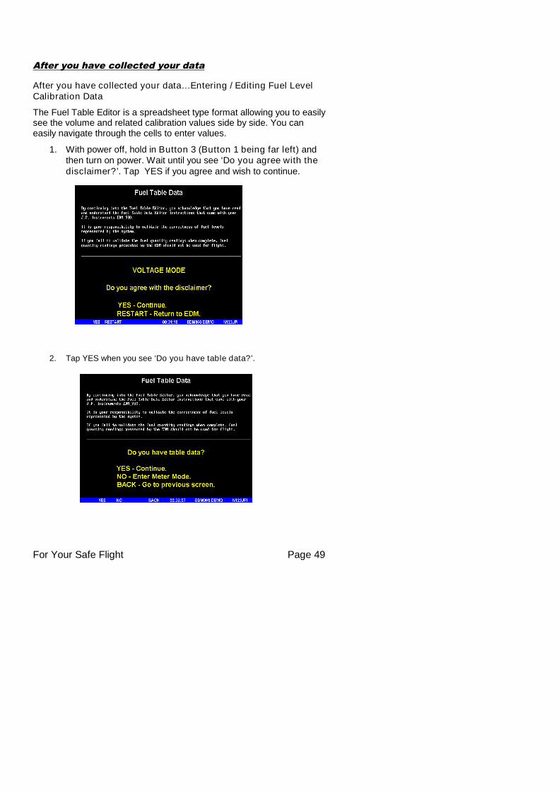
The Fuel Table Editor is a spreadsheet type format allowing you to easilysee the volume and related calibration values side by side. You caneasily navigate through the cells to enter values.
1. With power off, hold in Button 3 (Button 1 being far left) andthen turn on power. Wait until you see ‘Do you agree with thedisclaimer?’. Tap YES if you agree and wish to continue.
2. Tap YES when you see ‘Do you have table data?’.
For Your Safe Flight Page 50
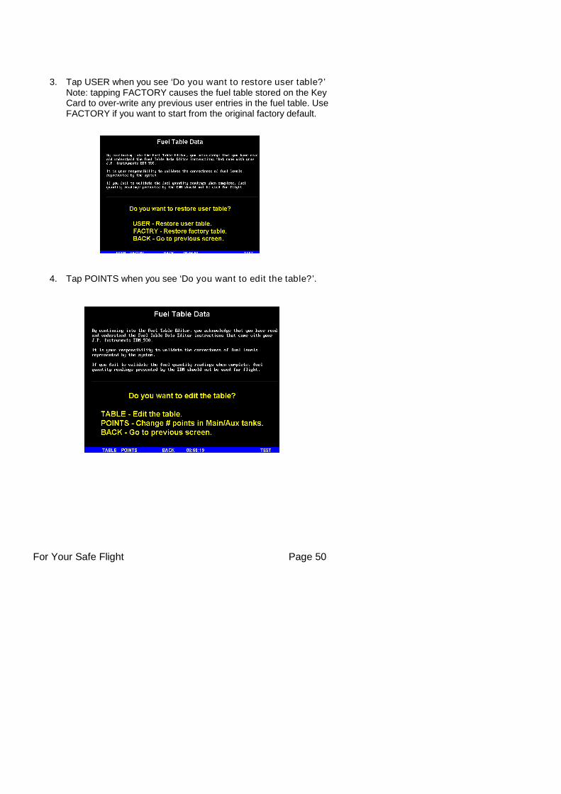
3. Tap USER when you see ‘Do you want to restore user table?’Note: tapping FACTORY causes the fuel table stored on the KeyCard to over-write any previous user entries in the fuel table. UseFACTORY if you want to start from the original factory default.
4. Tap POINTS when you see ‘Do you want to edit the table?’.
For Your Safe Flight Page 51
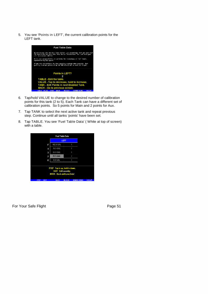
5. You see ‘Points in LEFT’, the current calibration points for theLEFT tank.
6. Tap/hold VALUE to change to the desired number of calibrationpoints for this tank (2 to 5). Each Tank can have a different set ofcalibration points. So 5 points for Main and 2 points for Aux.
7. Tap TANK to select the next active tank and repeat previousstep. Continue until all tanks ‘points’ have been set.
8. Tap TABLE. You see ‘Fuel Table Data’ ( White at top of screen)with a table.
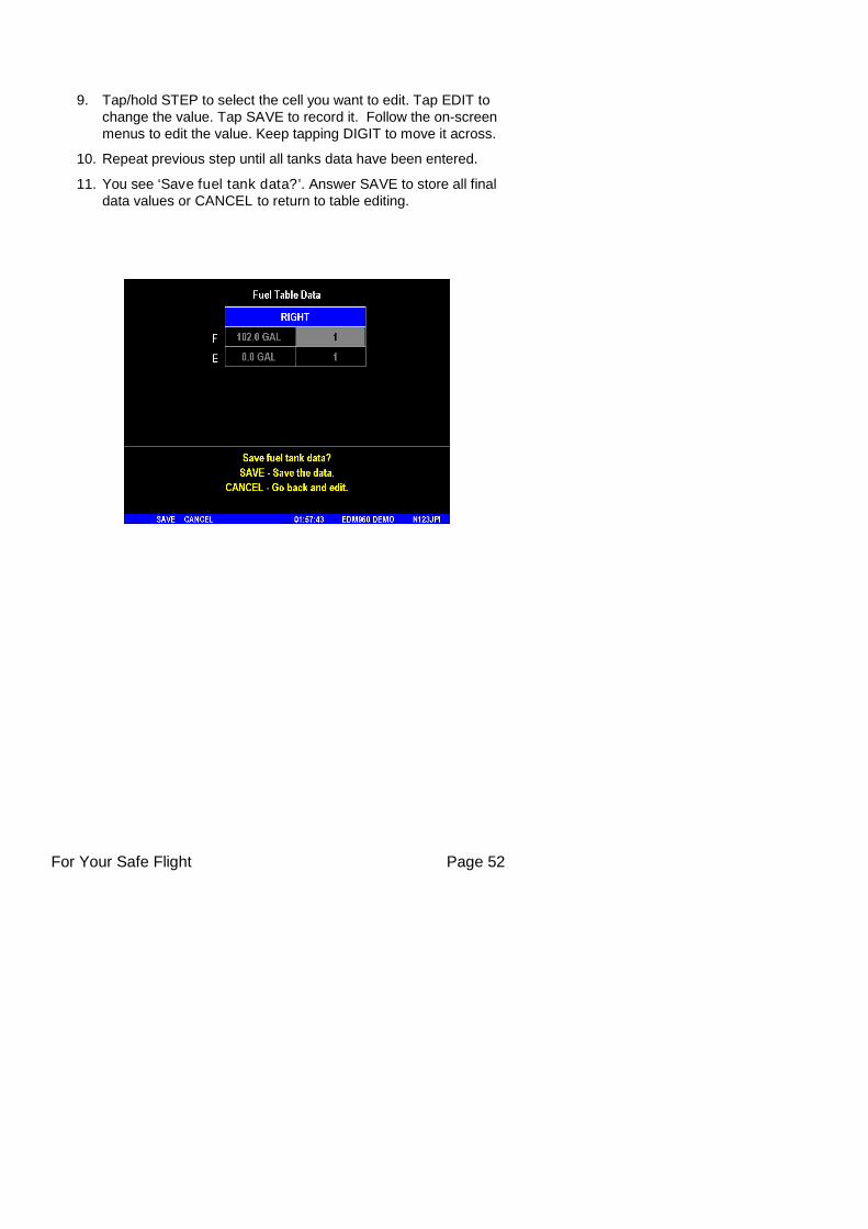
For Your Safe Flight Page 52
9. Tap/hold STEP to select the cell you want to edit. Tap EDIT tochange the value. Tap SAVE to record it. Follow the on-screenmenus to edit the value. Keep tapping DIGIT to move it across.
10. Repeat previous step until all tanks data have been entered.
11. You see ‘Save fuel tank data?’. Answer SAVE to store all finaldata values or CANCEL to return to table editing.
For Your Safe Flight Page 53
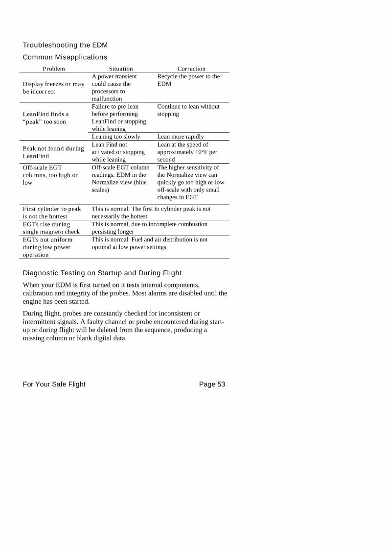
Troubleshooting the EDM
Common Misapplications
Problem Situation Correction
Display freezes or maybe incorrect
A power transientcould cause theprocessors tomalfunction
Recycle the power to theEDM
LeanFind finds a“peak” too soon
Failure to pre-leanbefore performingLeanFind or stoppingwhile leaning
Continue to lean withoutstopping
Leaning too slowly Lean more rapidly
Peak not found duringLeanFind
Lean Find notactivated or stoppingwhile leaning
Lean at the speed ofapproximately 10°F persecond
Off-scale EGTcolumns, too high orlow
Off-scale EGT columnreadings. EDM in theNormalize view (bluescales)
The higher sensitivity ofthe Normalize view canquickly go too high or lowoff-scale with only smallchanges in EGT.
First cylinder to peakis not the hottest
This is normal. The first to cylinder peak is notnecessarily the hottest
EGTs rise duringsingle magneto check
This is normal, due to incomplete combustionpersisting longer
EGTs not uniformduring low poweroperation
This is normal. Fuel and air distribution is notoptimal at low power settings
Diagnostic Testing on Startup and During Flight
When your EDM is first turned on it tests internal components,calibration and integrity of the probes. Most alarms are disabled until theengine has been started.
During flight, probes are constantly checked for inconsistent orintermittent signals. A faulty channel or probe encountered during start-up or during flight will be deleted from the sequence, producing amissing column or blank digital data.
For Your Safe Flight Page 54
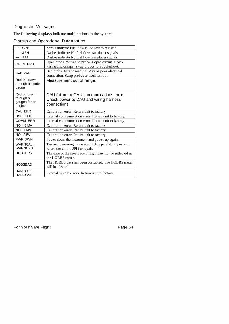
Diagnostic Messages
The following displays indicate malfunctions in the system:
Startup and Operational Diagnostics
0.0 GPH Zero’s indicate Fuel flow is too low to register--- GPH Dashes indicate No fuel flow transducer signals--- H.M Dashes indicate No fuel flow transducer signals
OPEN PRBOpen probe. Wiring to probe is open circuit. Checkwiring and crimps. Swap probes to troubleshoot.
BAD-PRBBad probe. Erratic reading. May be poor electricalconnection. Swap probes to troubleshoot.
Red ‘X’ drawnthrough a singlegauge
Measurement out of range.
Red ‘X’ drawnthrough allgauges for anengine
DAU failure or DAU communications error.Check power to DAU and wiring harnessconnections.
CAL ERR Calibration error. Return unit to factory.DSP XXX Internal communication error. Return unit to factory.COMM ERR Internal communication error. Return unit to factory.NO I 5 MV Calibration error. Return unit to factory.NO 50MV Calibration error. Return unit to factory.NO 2.5V Calibration error. Return unit to factory.PWR DWN Power down the instrument and power up again.
WARNCAL,WARNCFG
Transient warning messages. If they persistently occur,return the unit to JPI for repair.
HOBSERR The time of the most recent flight may not be reflected inthe HOBBS meter.
HOBSBADThe HOBBS data has been corrupted. The HOBBS meterwill be cleared.
HANGCFG,HANGCAL
Internal system errors. Return unit to factory.
For Your Safe Flight Page 55
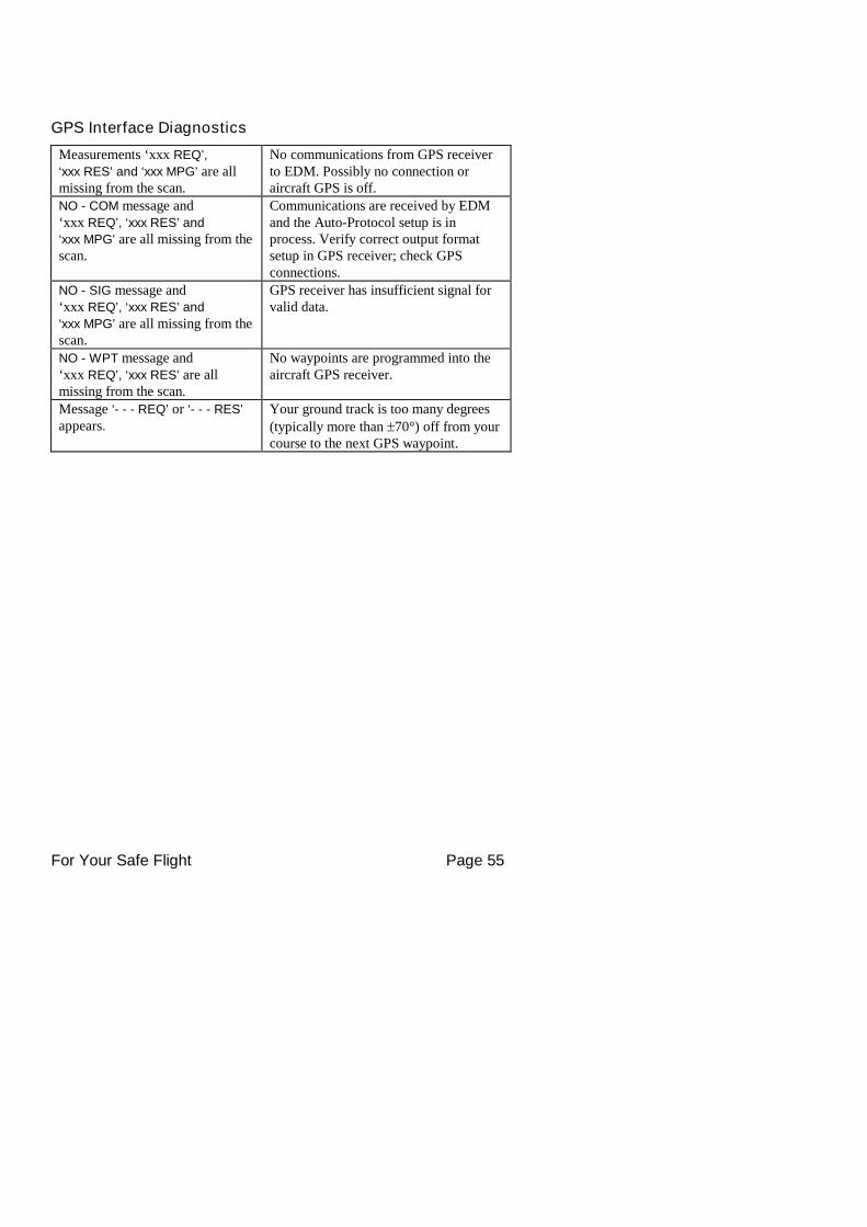
GPS Interface Diagnostics
Measurements ‘xxx REQ’,
‘xxx RES’ and ‘xxx MPG’ are allmissing from the scan.
No communications from GPS receiverto EDM. Possibly no connection oraircraft GPS is off.
NO - COM message and‘xxx REQ’, ‘xxx RES’ and
‘xxx MPG’ are all missing from thescan.
Communications are received by EDMand the Auto-Protocol setup is inprocess. Verify correct output formatsetup in GPS receiver; check GPSconnections.
NO - SIG message and‘xxx REQ’, ‘xxx RES’ and
‘xxx MPG’ are all missing from thescan.
GPS receiver has insufficient signal forvalid data.
NO - WPT message and‘xxx REQ’, ‘xxx RES’ are allmissing from the scan.
No waypoints are programmed into theaircraft GPS receiver.
Message ‘- - - REQ’ or ‘- - - RES’
appears.
Your ground track is too many degrees
(typically more than 70°) off from yourcourse to the next GPS waypoint.
For Your Safe Flight Page 56
Section 12 - Appendices
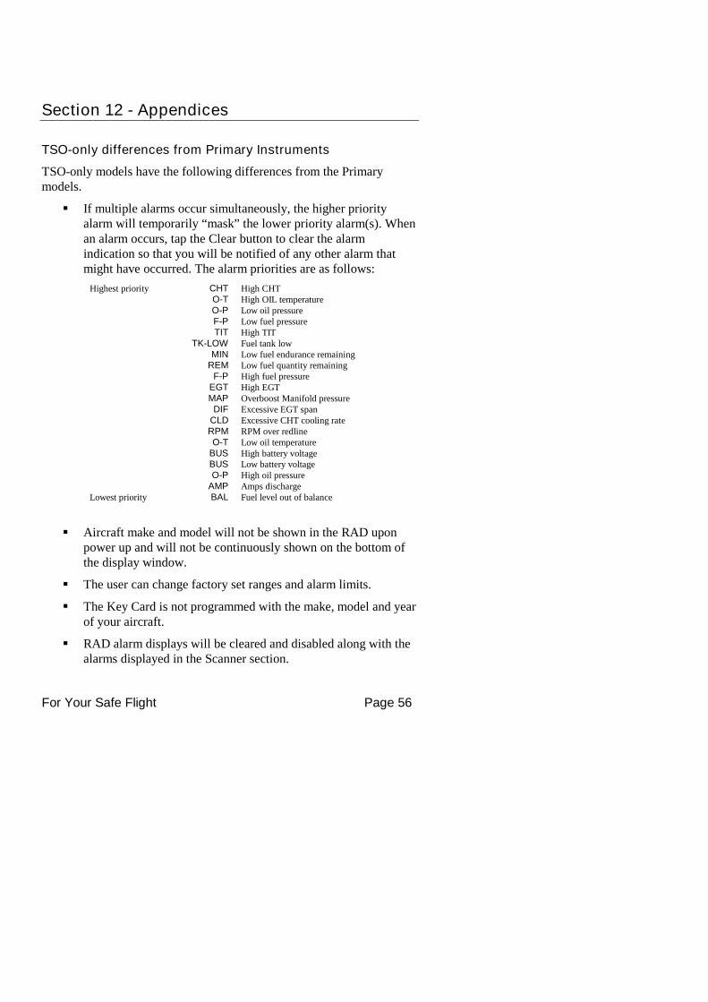
TSO-only differences from Primary Instruments
TSO-only models have the following differences from the Primarymodels.
If multiple alarms occur simultaneously, the higher priorityalarm will temporarily “mask” the lower priority alarm(s). Whenan alarm occurs, tap the Clear button to clear the alarmindication so that you will be notified of any other alarm thatmight have occurred. The alarm priorities are as follows:
Highest priority CHT High CHTO-T High OIL temperatureO-P Low oil pressureF-P Low fuel pressureTIT High TIT
TK-LOW Fuel tank lowMIN Low fuel endurance remaining
REM Low fuel quantity remainingF-P High fuel pressure
EGT High EGTMAP Overboost Manifold pressureDIF Excessive EGT span
CLD Excessive CHT cooling rateRPM RPM over redlineO-T Low oil temperature
BUS High battery voltageBUS Low battery voltageO-P High oil pressure
AMP Amps dischargeLowest priority BAL Fuel level out of balance
Aircraft make and model will not be shown in the RAD uponpower up and will not be continuously shown on the bottom ofthe display window.
The user can change factory set ranges and alarm limits.
The Key Card is not programmed with the make, model and yearof your aircraft.
RAD alarm displays will be cleared and disabled along with thealarms displayed in the Scanner section.
For Your Safe Flight Page 57
JPI Hastaloy-X probes may read as much as 100°F higher thanthe factory installed TIT probe. However, note that the enginewas certified with the factory-installed TIT probe and gauge, andthis gauge reading is the limiting factor when adjusting yourengine.
The user can assign the nine graphs in the bar graphs section tothe desired measurements .
Most measurements can be excluded from the Automatic mode.
Shock Cooling
Cooling the cylinders too fast can result in cracking and eventual failure.Lycoming Service Instruction 1094D (March 25, 1994) on Fuel MixtureLeaning Procedures states:
“At all times, caution must be taken not to shock cool the cylinders. Themaximum recommended temperature change should not exceed 50°Fper minute.”
JPI checks shock cooling on all cylinders displaying the highest readingcylinder.
For Your Safe Flight Page 58
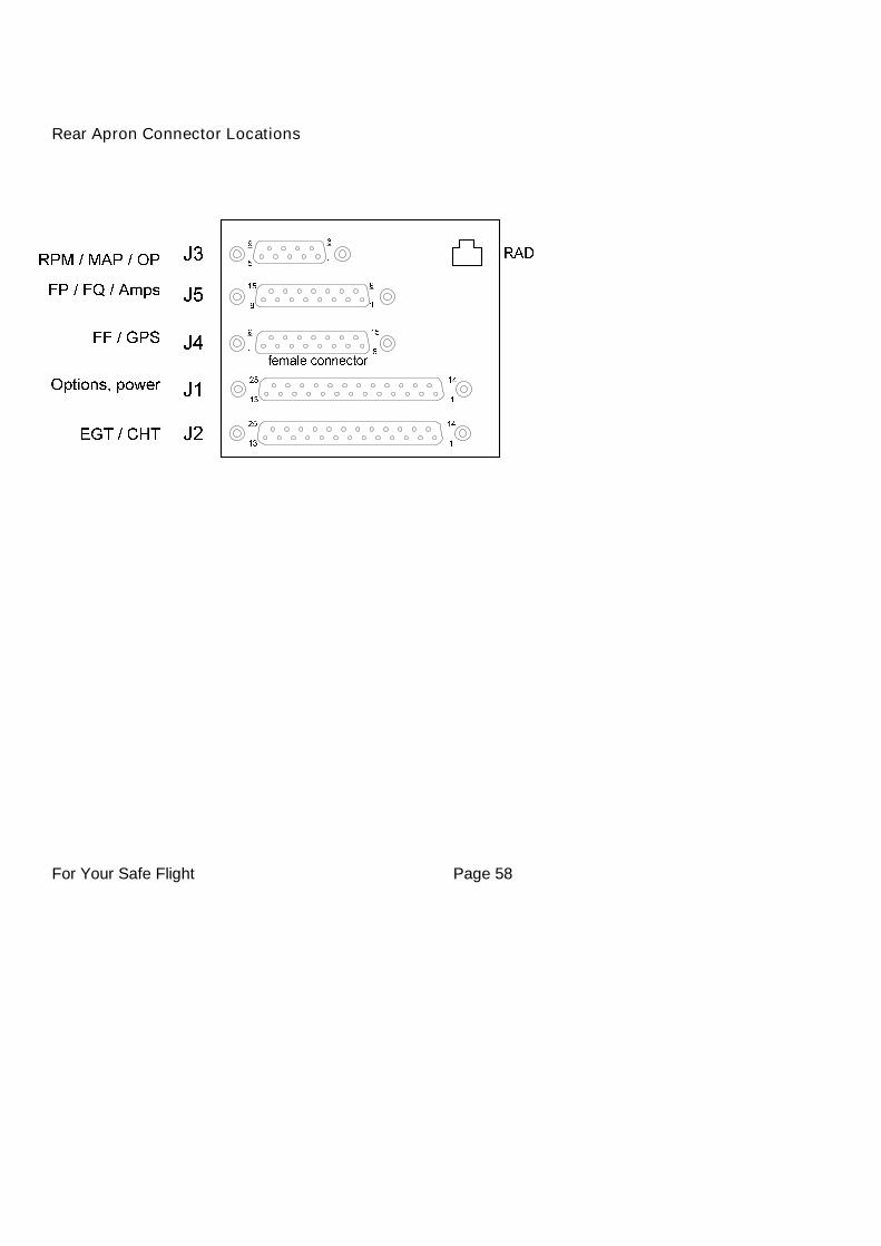
Rear Apron Connector Locations
For Your Safe Flight Page 59
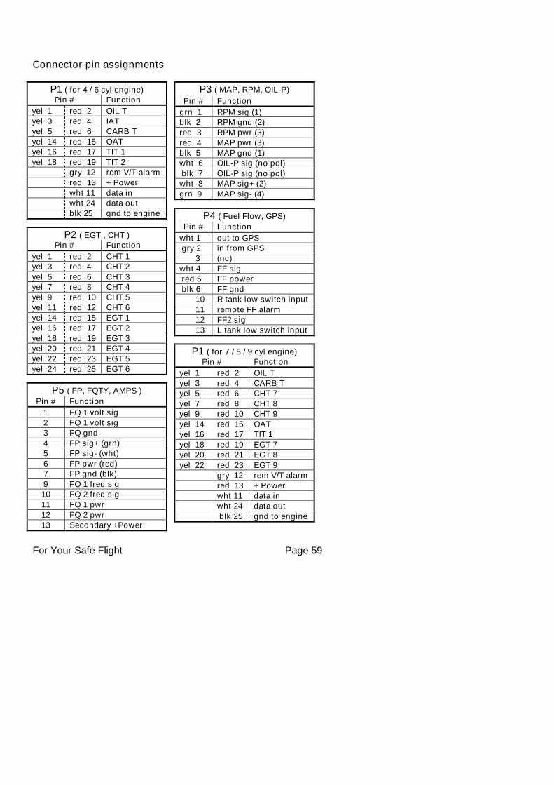
Connector pin assignments
P1 ( for 7 / 8 / 9 cyl engine)Pin # Function
yel 1 red 2 OIL Tyel 3 red 4 CARB Tyel 5 red 6 CHT 7
yel 7 red 8 CHT 8yel 9 red 10 CHT 9
yel 14 red 15 OATyel 16 red 17 TIT 1
yel 18 red 19 EGT 7yel 20 red 21 EGT 8
yel 22 red 23 EGT 9gry 12 rem V/T alarm
red 13 + Powerwht 11 data in
wht 24 data outblk 25 gnd to engine
P1 ( for 4 / 6 cyl engine)Pin # Function
yel 1 red 2 OIL Tyel 3 red 4 IATyel 5 red 6 CARB T
yel 14 red 15 OATyel 16 red 17 TIT 1
yel 18 red 19 TIT 2gry 12 rem V/T alarm
red 13 + Powerwht 11 data in
wht 24 data outblk 25 gnd to engine
P2 ( EGT , CHT )Pin # Function
yel 1 red 2 CHT 1yel 3 red 4 CHT 2
yel 5 red 6 CHT 3yel 7 red 8 CHT 4
yel 9 red 10 CHT 5yel 11 red 12 CHT 6
yel 14 red 15 EGT 1yel 16 red 17 EGT 2
yel 18 red 19 EGT 3yel 20 red 21 EGT 4
yel 22 red 23 EGT 5yel 24 red 25 EGT 6
P4 ( Fuel Flow, GPS)
Pin # Function
wht 1 out to GPSgry 2 in from GPS
3 (nc)
wht 4 FF sigred 5 FF power
blk 6 FF gnd10 R tank low switch input
11 remote FF alarm12 FF2 sig
13 L tank low switch input
P3 ( MAP, RPM, OIL-P)
Pin # Function
grn 1 RPM sig (1)blk 2 RPM gnd (2)
red 3 RPM pwr (3)red 4 MAP pwr (3)
blk 5 MAP gnd (1)wht 6 OIL-P sig (no pol)
blk 7 OIL-P sig (no pol)wht 8 MAP sig+ (2)
grn 9 MAP sig- (4)
P5 ( FP, FQTY, AMPS )
Pin # Function
1 FQ 1 volt sig2 FQ 1 volt sig3 FQ gnd
4 FP sig+ (grn)5 FP sig- (wht)
6 FP pwr (red)7 FP gnd (blk)
9 FQ 1 freq sig10 FQ 2 freq sig
11 FQ 1 pwr12 FQ 2 pwr
13 Secondary +Power
For Your Safe Flight Page 60
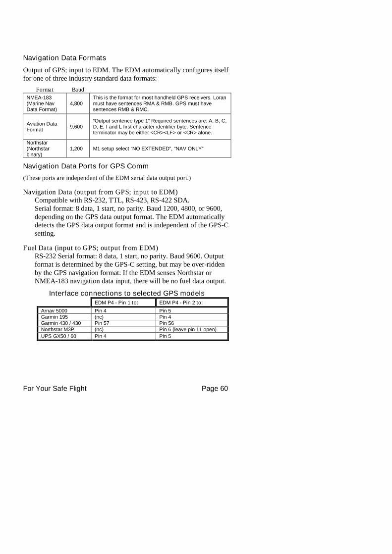
Navigation Data Formats
Output of GPS; input to EDM. The EDM automatically configures itselffor one of three industry standard data formats:
Format Baud
NMEA-183(Marine NavData Format)
4,800This is the format for most handheld GPS receivers. Loranmust have sentences RMA & RMB. GPS must havesentences RMB & RMC.
Aviation DataFormat
9,600“Output sentence type 1” Required sentences are: A, B, C,D, E, I and L first character identifier byte. Sentenceterminator may be either <CR><LF> or <CR> alone.
Northstar(Northstarbinary)
1,200 M1 setup select “NO EXTENDED”, “NAV ONLY”
Navigation Data Ports for GPS Comm
(These ports are independent of the EDM serial data output port.)
Navigation Data (output from GPS; input to EDM)Compatible with RS-232, TTL, RS-423, RS-422 SDA.Serial format: 8 data, 1 start, no parity. Baud 1200, 4800, or 9600,depending on the GPS data output format. The EDM automaticallydetects the GPS data output format and is independent of the GPS-Csetting.
Fuel Data (input to GPS; output from EDM)RS-232 Serial format: 8 data, 1 start, no parity. Baud 9600. Outputformat is determined by the GPS-C setting, but may be over-riddenby the GPS navigation format: If the EDM senses Northstar orNMEA-183 navigation data input, there will be no fuel data output.
Interface connections to selected GPS modelsEDM P4 - Pin 1 to: EDM P4 - Pin 2 to:
Arnav 5000 Pin 4 Pin 5Garmin 195 (nc) Pin 4Garmin 430 / 430 Pin 57 Pin 56Northstar M3P (nc) Pin 6 (leave pin 11 open)
UPS GX50 / 60 Pin 4 Pin 5
For Your Safe Flight Page 61
Section 13 - Technical Support
JPI offers both e-mail and telephone technical support. Have your modeland serial number ready when you call. Call JPI for a returnauthorization number before returning any equipment.
J.P.INSTRUMENTS Inc.3185 B AirwayCosta Mesa, CA 92626
Call: (800) 345-4574Web: www.jpinstruments.com or www.JPITech.com
Limited WarrantyJ.P. Instruments Inc. (JPI) warrants all parts in your new EDM to be free from defects inmaterial and workmanship under normal use. Our obligation under this warranty islimited to overhaul or exchange of any defective part of this unit if the part is returned,shipping prepaid, within three years for electronics and one year for probes from the dateof original purchase. Installation labor is the responsibility of the aircraft owner.Homebuilt aircraft warranty starts when the aircraft is certified for flight. Replacementparts carry a warranty for the balance of the warranty period.
Under this warranty, JPI is not responsible for any service charges, including removal,installation, nor any other consequential damages. JPI incurs no obligation under thiswarranty unless a Warranty Registration Certificate describing the warranted product hasbeen completed and mailed to JPI with all information requested.
This warranty is void on any product which has been subject to misuse, accident, damagecaused by negligence, damage in transit, handling or modification which, in the opinionof JPI, has been altered or repaired in any way that effects the reliability or detracts fromthe performance of the product, or any product whereon the serial number has beenaltered, defaced, effaced or destroyed.
This warranty is in lieu of all other warranties expressed or implied and other obligationsof liability on JPI’s part, and it neither assumes nor authorizes any other person toassume for JPI any other liability in connection with the sale of JPI products.
To initiate this warranty, the aircraft owner must submit a completed Data LoggingWorksheet to JPI. Upon receiving a completed worksheet, JPI will initiate the warrantyfrom the date of original purchase. Any replacement parts carry a warranty that extendsfor the balance of the period of the original warranty. For homebuilt aircraft the warrantystarts when the aircraft is certificated for flight and noted on the warranty card.
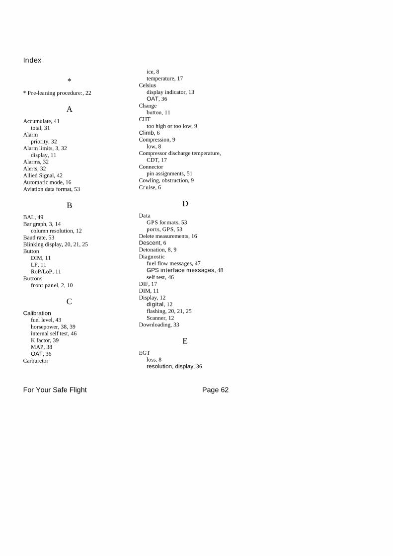
For Your Safe Flight Page 62
Index
*
* Pre-leaning procedure:, 22
A
Accumulate, 41total, 31
Alarmpriority, 32
Alarm limits, 3, 32display, 11
Alarms, 32Alerts, 32Allied Signal, 42Automatic mode, 16Aviation data format, 53
B
BAL, 49Bar graph, 3, 14
column resolution, 12Baud rate, 53Blinking display, 20, 21, 25Button
DIM, 11LF, 11RoP/LoP, 11
Buttonsfront panel, 2, 10
C
Calibrationfuel level, 43horsepower, 38, 39internal self test, 46K factor, 39MAP, 38OAT, 36
Carburetor
ice, 8temperature, 17
Celsiusdisplay indicator, 13OAT, 36
Changebutton, 11
CHTtoo high or too low, 9
Climb, 6Compression, 9
low, 8Compressor discharge temperature,
CDT, 17Connector
pin assignments, 51Cowling, obstruction, 9Cruise, 6
D
DataGPS formats, 53ports, GPS, 53
Delete measurements, 16Descent, 6Detonation, 8, 9Diagnostic
fuel flow messages, 47GPS interface messages, 48self test, 46
DIF, 17DIM, 11Display, 12
digital, 12flashing, 20, 21, 25Scanner, 12
Downloading, 33
E
EGTloss, 8resolution, display, 36

For Your Safe Flight Page 63
select switch, 31too high, 8, 46too low, 8, 46
Eliminate measurements, 16Engine
diagnosis chart, 8limits, normal, 7run-up, 5
Error messages, 46Exclude measurements, 16Exhaust leak, 9EzConfig, 35
F
Fahrenheitdisplay indicator, 13OAT, 36
Failure to pre-lean, 46Features, 5FF, select switch, 31First cylinder to peak, 22First time setup, 35Flashing display, 20, 21, 25Flat EGT response, 8, 9Fuel
accumulate, 31injectors, 9injectors, clogged, 6, 8Octane, 9pump, 9remaining, 17required, 17reserve, 17start up, 2, 27used, 17
Fuel flow, 26connector, 51diagnostics messages, 47
Fuel levelcalibration, 43
Full throttle, 6
G
GAMI, 18, 25Gasket, manifold, 9Getting started, 1
GPSdata formats, 53data ports, 53interface diagnostics, 48
H
H.S, 17Hastaloy, 25, 50History
display, 59Hobbs, 11
display, 15Holding a button, 2, 10Horsepower
calibration, 39constant setting, 38
I
Ice, carburetor or induction, 8Ignition, 9
timing, 8Include measurements, 16Indexing
scan rate, 36Induction, 8
air temperature, IAT, 17Informing the EDM-930
startup fuel, 27Intake valve, 8Interpreting
data, 5display, 8
K
K factorcalibration, 41
Key card, 1, 42K-factor
calibration, 39
L
Leakmanifold, 9
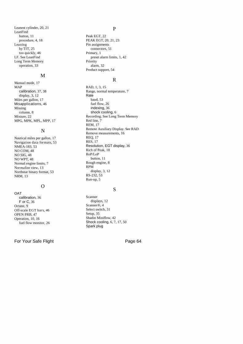
For Your Safe Flight Page 64
Leanest cylinder, 20, 21LeanFind
button, 11procedure, 4, 18
Leaningby TIT, 25too quickly, 46
LF. See LeanFindLong Term Memory
operation, 33
M
Manual mode, 17MAP
calibration, 37, 38display, 3, 12
Miles per gallon, 17Misapplications, 46Missing
column, 8Mixture, 22MPG, MPK, MPL, MPP, 17
N
Nautical miles per gallon, 17Navigation data formats, 53NMEA-183, 53NO COM, 48NO SIG, 48NO WPT, 48Normal engine limits, 7Normalize view, 13Northstar binary format, 53NRM, 13
O
OATcalibration, 36F or C, 36
Octane, 9Off-scale EGT bars, 46OPEN PRB, 47Operation, 10, 16
fuel flow monitor, 26
P
Peak EGT, 22PEAK EGT, 20, 21, 23Pin assignments
connectors, 51Primary, 1
preset alarm limits, 1, 42Priority
alarm, 32Product support, 54
R
RAD, 1, 3, 15Range, normal temperature, 7Rate
baud, 53fuel flow, 26indexing, 36shock cooling, 6
Recording. See Long Term MemoryRed line, 7REM, 17Remote Auxiliary Display. See RADRemove measurements, 16REQ, 17RES, 17Resolution, EGT display, 36Rich of Peak, 18RoP/LoP
button, 11Rough engine, 8RPM
display, 3, 12RS-232, 53Run-up, 5
S
Scannerdisplays, 12
Scanner®, 4Select switch, 31Setup, 35Shadin Miniflow, 42Shock cooling, 6, 7, 17, 50Spark plug
For Your Safe Flight Page 65
fouling, 5, 8Standard view, 13Startup
diagnostics, 46fuel, 2, 27
Stuck valve, 8Switch, select, 31
T
Tachometer. See RPMTake-off, 6Tapping a button, 2, 10Technical support, 54Test, self, 46Time to empty, 17Timing, ignition, 8TIT, 25Toggle, N, P, 13Total
fuel used, 17, 41Total fuel, 31Transducer, fuel flow, 26Trip total, 41Troubleshooting
engine, 8
GPS, 48instrument, 46
Trouibleshootingfuel flow, 47
TSO-only models, 49Turbocharged Engines, 25
U
Uniform, CHT, EGT not, 8USD, 17
V
Valvelifter, 8stuck, 8
Vapor, 9View
change diagram, 11normalize, Standard, 13
W
Warranty, 54
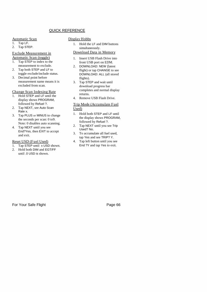
For Your Safe Flight Page 66
QUICK REFERENCE
Automatic Scan1. Tap LF.2. Tap STEP.
Exclude Measurement inAutomatic Scan (toggle)1. Tap STEP to index to the
measurement to exclude.2. Tap both STEP and LF to
toggle exclude/include status.3. Decimal point before
measurement name means it isexcluded from scan.
Change Scan Indexing Rate1. Hold STEP and LF until the
display shows PROGRAM,followed by Refuel ?.
2. Tap NEXT, see Auto ScanRate x.
3. Tap PLUS or MINUS to changethe seconds per scan: 0 to9.Note: 0 disables auto scanning.
4. Tap NEXT until you seeEnd?Yes, then EXIT to acceptand exit.
Reset USD (Fuel Used)1. Tap STEP until x USD shown.2. Hold both DIM and EGT/FF
until .0 USD is shown.
Display Hobbs
1. Hold the LF and DIM buttonssimultaneously.
Download Data in Memory
1. Insert USB Flash Drive intofront USB port on EDM.
2. DOWNLOAD: NEW (latestflight) or tap CHANGE to seeDOWNLOAD: ALL (all storedflights).
3. Tap STEP and wait untildownload progress barcompletes and normal displayreturns.
4. Remove USB Flash Drive.
Trip Mode (Accumulate FuelUsed)
1. Hold both STEP and LF untilthe display shows PROGRAM,followed by Refuel ?.
2. Tap NEXT until you see TripUsed? No.
3. To accumulate all fuel used,tap Yes and see TRIP? Y.
4. Tap left button until you seeEnd ?Y and tap Yes to exit.
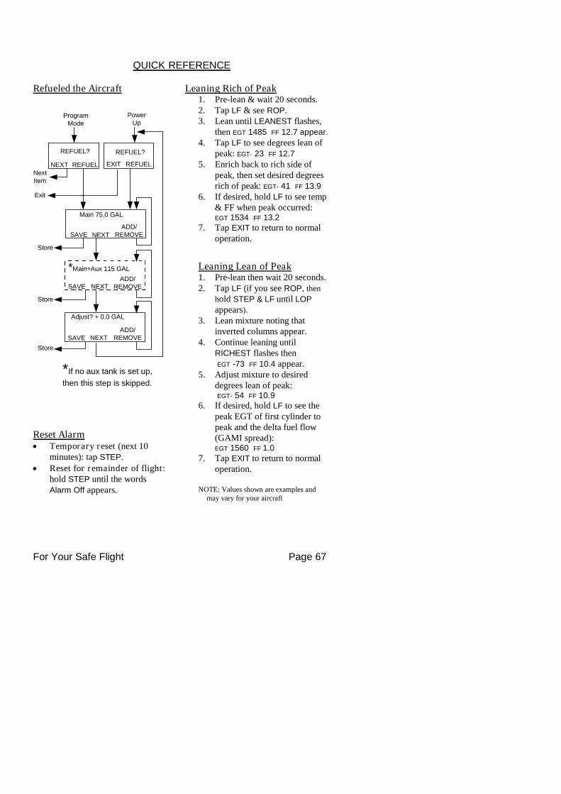
For Your Safe Flight Page 67
PowerUp
Main 75.0 GAL
Adjust? + 0.0 GAL
*Main+Aux 115 GAL
ProgramMode
REFUEL?
REFUELEXIT
REFUEL?
REFUELNEXT
SAVE NEXT
SAVE NEXT
SAVE NEXTADD/
REMOVE
NextItem
Exit
Store
Store
Store
*If no aux tank is set up,
then this step is skipped.
ADD/REMOVE
ADD/REMOVE
QUICK REFERENCE
Refueled the Aircraft
Reset Alarm Temporary reset (next 10
minutes): tap STEP. Reset for remainder of flight:
hold STEP until the wordsAlarm Off appears.
Leaning Rich of Peak1. Pre-lean & wait 20 seconds.2. Tap LF & see ROP.3. Lean until LEANEST flashes,
then EGT 1485 FF 12.7 appear.
4. Tap LF to see degrees lean ofpeak: EGT- 23 FF 12.7
5. Enrich back to rich side ofpeak, then set desired degreesrich of peak: EGT- 41 FF 13.9
6. If desired, hold LF to see temp& FF when peak occurred:EGT 1534 FF 13.2
7. Tap EXIT to return to normaloperation.
Leaning Lean of Peak1. Pre-lean then wait 20 seconds.2. Tap LF (if you see ROP, then
hold STEP & LF until LOP
appears).
3. Lean mixture noting thatinverted columns appear.
4. Continue leaning untilRICHEST flashes thenEGT -73 FF 10.4 appear.
5. Adjust mixture to desireddegrees lean of peak:EGT- 54 FF 10.9
6. If desired, hold LF to see thepeak EGT of first cylinder topeak and the delta fuel flow(GAMI spread):EGT 1560 FF 1.0
7. Tap EXIT to return to normaloperation.
NOTE: Values shown are examples andmay vary for your aircraft