Embed Size (px)
Citation preview
IEC 60770-3 Edition 2.0 2014-05
INTERNATIONAL STANDARD NORME INTERNATIONALE
Transmitters for use in industrial-process control systems – Part 3: Methods for performance evaluation of intelligent transmitters Transmetteurs utilisés dans les systèmes de commande des processus industriels – Partie 3: Méthodes d’évaluation des performances des transmetteurs intelligents
IEC
607
70-3
:201
4-05
(en-
fr)
®
colourinside
iTeh STANDARD PREVIEW(standards.iteh.ai)
IEC 60770-3:2014https://standards.iteh.ai/catalog/standards/sist/5ff7d0d1-f3fb-4768-b171-
465f0ec8fae4/iec-60770-3-2014
THIS PUBLICATION IS COPYRIGHT PROTECTED Copyright © 2014 IEC, Geneva, Switzerland All rights reserved. Unless otherwise specified, no part of this publication may be reproduced or utilized in any form or by any means, electronic or mechanical, including photocopying and microfilm, without permission in writing from either IEC or IEC's member National Committee in the country of the requester. If you have any questions about IEC copyright or have an enquiry about obtaining additional rights to this publication, please contact the address below or your local IEC member National Committee for further information. Droits de reproduction réservés. Sauf indication contraire, aucune partie de cette publication ne peut être reproduite ni utilisée sous quelque forme que ce soit et par aucun procédé, électronique ou mécanique, y compris la photocopie et les microfilms, sans l'accord écrit de l'IEC ou du Comité national de l'IEC du pays du demandeur. Si vous avez des questions sur le copyright de l'IEC ou si vous désirez obtenir des droits supplémentaires sur cette publication, utilisez les coordonnées ci-après ou contactez le Comité national de l'IEC de votre pays de résidence.
IEC Central Office Tel.: +41 22 919 02 11 3, rue de Varembé Fax: +41 22 919 03 00 CH-1211 Geneva 20 [email protected] Switzerland www.iec.ch
About the IEC The International Electrotechnical Commission (IEC) is the leading global organization that prepares and publishes International Standards for all electrical, electronic and related technologies. About IEC publications The technical content of IEC publications is kept under constant review by the IEC. Please make sure that you have the latest edition, a corrigenda or an amendment might have been published. IEC Catalogue - webstore.iec.ch/catalogue The stand-alone application for consulting the entire bibliographical information on IEC International Standards, Technical Specifications, Technical Reports and other documents. Available for PC, Mac OS, Android Tablets and iPad. IEC publications search - www.iec.ch/searchpub The advanced search enables to find IEC publications by a variety of criteria (reference number, text, technical committee,…). It also gives information on projects, replaced and withdrawn publications. IEC Just Published - webstore.iec.ch/justpublished Stay up to date on all new IEC publications. Just Published details all new publications released. Available online and also once a month by email.
Electropedia - www.electropedia.org The world's leading online dictionary of electronic and electrical terms containing more than 30 000 terms and definitions in English and French, with equivalent terms in 14 additional languages. Also known as the International Electrotechnical Vocabulary (IEV) online. IEC Glossary - std.iec.ch/glossary More than 55 000 electrotechnical terminology entries in English and French extracted from the Terms and Definitions clause of IEC publications issued since 2002. Some entries have been collected from earlier publications of IEC TC 37, 77, 86 and CISPR. IEC Customer Service Centre - webstore.iec.ch/csc If you wish to give us your feedback on this publication or need further assistance, please contact the Customer Service Centre: [email protected].
A propos de l'IEC La Commission Electrotechnique Internationale (IEC) est la première organisation mondiale qui élabore et publie des Normes internationales pour tout ce qui a trait à l'électricité, à l'électronique et aux technologies apparentées. A propos des publications IEC Le contenu technique des publications IEC est constamment revu. Veuillez vous assurer que vous possédez l’édition la plus récente, un corrigendum ou amendement peut avoir été publié. Catalogue IEC - webstore.iec.ch/catalogue Application autonome pour consulter tous les renseignements bibliographiques sur les Normes internationales, Spécifications techniques, Rapports techniques et autres documents de l'IEC. Disponible pour PC, Mac OS, tablettes Android et iPad. Recherche de publications IEC - www.iec.ch/searchpub La recherche avancée permet de trouver des publications IEC en utilisant différents critères (numéro de référence, texte, comité d’études,…). Elle donne aussi des informations sur les projets et les publications remplacées ou retirées. IEC Just Published - webstore.iec.ch/justpublished Restez informé sur les nouvelles publications IEC. Just Published détaille les nouvelles publications parues. Disponible en ligne et aussi une fois par mois par email.
Electropedia - www.electropedia.org Le premier dictionnaire en ligne de termes électroniques et électriques. Il contient plus de 30 000 termes et définitions en anglais et en français, ainsi que les termes équivalents dans 14 langues additionnelles. Egalement appelé Vocabulaire Electrotechnique International (IEV) en ligne. Glossaire IEC - std.iec.ch/glossary Plus de 55 000 entrées terminologiques électrotechniques, en anglais et en français, extraites des articles Termes et Définitions des publications IEC parues depuis 2002. Plus certaines entrées antérieures extraites des publications des CE 37, 77, 86 et CISPR de l'IEC. Service Clients - webstore.iec.ch/csc Si vous désirez nous donner des commentaires sur cette publication ou si vous avez des questions contactez-nous: [email protected].
iTeh STANDARD PREVIEW(standards.iteh.ai)
IEC 60770-3:2014https://standards.iteh.ai/catalog/standards/sist/5ff7d0d1-f3fb-4768-b171-
465f0ec8fae4/iec-60770-3-2014
IEC 60770-3 Edition 2.0 2014-05
INTERNATIONAL STANDARD NORME INTERNATIONALE
Transmitters for use in industrial-process control systems – Part 3: Methods for performance evaluation of intelligent transmitters Transmetteurs utilisés dans les systèmes de commande des processus industriels – Partie 3: Méthodes d’évaluation des performances des transmetteurs intelligents
INTERNATIONAL ELECTROTECHNICAL COMMISSION
COMMISSION ELECTROTECHNIQUE INTERNATIONALE XA ICS 25.040.40
PRICE CODE CODE PRIX
ISBN 978-2-8322-1629-3
® Registered trademark of the International Electrotechnical Commission Marque déposée de la Commission Electrotechnique Internationale
®
Warning! Make sure that you obtained this publication from an authorized distributor. Attention! Veuillez vous assurer que vous avez obtenu cette publication via un distributeur agréé.
colourinside
iTeh STANDARD PREVIEW(standards.iteh.ai)
IEC 60770-3:2014https://standards.iteh.ai/catalog/standards/sist/5ff7d0d1-f3fb-4768-b171-
465f0ec8fae4/iec-60770-3-2014
– 2 – IEC 60770-3:2014 © IEC 2014
CONTENTS
FOREWORD ........................................................................................................................... 5 INTRODUCTION ..................................................................................................................... 7 1 Scope .............................................................................................................................. 8 2 Normative references ....................................................................................................... 8 3 Terms and definitions ...................................................................................................... 9 4 Design assessment ........................................................................................................ 10
4.1 General ............................................................................................................ 10 4.2 Transmitter analysis ......................................................................................... 11
4.2.1 General .......................................................................................... 11 4.2.2 Data processing subsystem............................................................. 12 4.2.3 Sensor subsystem........................................................................... 12 4.2.4 Human interface ............................................................................. 13 4.2.5 Communication interface ................................................................. 13 4.2.6 Electrical output subsystem ............................................................. 13 4.2.7 Power supply unit ............................................................................ 14 4.2.8 External functionality ....................................................................... 14 4.2.9 Cycle times (ct) ............................................................................... 14
4.3 Aspects to be reviewed .................................................................................... 14 4.3.1 General .......................................................................................... 14 4.3.2 Functionality ................................................................................... 15 4.3.3 Configurability ................................................................................. 16 4.3.4 Hardware configuration ................................................................... 17 4.3.5 Adjustment and tuning .................................................................... 18 4.3.6 Operability ...................................................................................... 19 4.3.7 Dependability .................................................................................. 20 4.3.8 Manufacturer's support ................................................................... 21 4.3.9 Reporting ........................................................................................ 22
4.4 Documentary information .................................................................................. 22 5 Performance testing ....................................................................................................... 23
5.1 General ............................................................................................................ 23 5.2 Instrument considerations ................................................................................ 23
5.2.1 General .......................................................................................... 23 5.2.2 Example of a single variable transmitter .......................................... 24 5.2.3 Example of a derived variable transmitter ........................................ 24
5.3 Measurement considerations ............................................................................ 25 5.3.1 General .......................................................................................... 25 5.3.2 Single variables .............................................................................. 25 5.3.3 Derived variable .............................................................................. 26
5.4 Test facilities .................................................................................................... 26 5.4.1 General .......................................................................................... 26 5.4.2 Signal generator ............................................................................. 27 5.4.3 Output load/receiver ........................................................................ 27 5.4.4 Control and data acquisition ............................................................ 28
5.5 Transmitter under test (testing precautions) ...................................................... 28 5.6 Reference conditions for performance tests ...................................................... 28 5.7 Test procedures for tests under reference conditions ........................................ 29
iTeh STANDARD PREVIEW(standards.iteh.ai)
IEC 60770-3:2014https://standards.iteh.ai/catalog/standards/sist/5ff7d0d1-f3fb-4768-b171-
465f0ec8fae4/iec-60770-3-2014
IEC 60770-3:2014 © IEC 2014 – 3 –
5.8 Test procedures for determination of the effects of influence quantities ............. 32 5.8.1 General .......................................................................................... 32 5.8.2 Process domain .............................................................................. 34 5.8.3 Utility domain .................................................................................. 39 5.8.4 Environmental domain ..................................................................... 41 5.8.5 Time domain ................................................................................... 43
6 Other considerations ...................................................................................................... 43 6.1 Safety .............................................................................................................. 43 6.2 Degree of protection provided by enclosures .................................................... 43 6.3 Electromagnetic emission ................................................................................. 44 6.4 Variants ........................................................................................................... 44
7 Evaluation report............................................................................................................ 44 Annex A (informative) Dependability testing .......................................................................... 45
A.1 General ............................................................................................................ 45 A.2 Design analysis ................................................................................................ 45 A.3 Reference conditions ........................................................................................ 45 A.4 Fault injection test for internal instrument failures ............................................. 47 A.5 Observations .................................................................................................... 47
A.5.1 General .......................................................................................... 47 A.5.2 Reporting and ranking of fault behaviour ......................................... 48
A.6 Human faults .................................................................................................... 50 A.6.1 Mis-operation test ........................................................................... 50 A.6.2 Maintenance error test .................................................................... 51 A.6.3 Expectations and reporting .............................................................. 51
Annex B (informative) Throughput testing ............................................................................. 52 B.1 General ............................................................................................................ 52 B.2 Transmitter throughput (stand-alone) ................................................................ 53
B.2.1 Reference conditions ...................................................................... 53 B.2.2 Test conditions ............................................................................... 53 B.2.3 Observations and measurements .................................................... 54
B.3 Throughput in a fieldbus configuration .............................................................. 54 B.3.1 Reference conditions ...................................................................... 54 B.3.2 Test conditions ............................................................................... 54 B.3.3 Observations and measurements .................................................... 55 B.3.4 Precautions..................................................................................... 55
Annex C (informative) Function block testing ........................................................................ 56 C.1 General ............................................................................................................ 56 C.2 General qualitative checks ............................................................................... 56 C.3 Time-dependent function blocks ....................................................................... 56 C.4 Time-independent function blocks .................................................................... 56
Bibliography .......................................................................................................................... 57 Figure 1 – Intelligent transmitter model .................................................................................. 12 Figure 2 – Basic test set-up ................................................................................................... 27 Figure 3 – Examples of step responses of electrical outputs of transmitters ........................... 31 Figure A.1 – Example schematic of a transmitter ................................................................... 46 Figure A.2 – Test tool for low impedance circuits and shared circuits ..................................... 47
iTeh STANDARD PREVIEW(standards.iteh.ai)
IEC 60770-3:2014https://standards.iteh.ai/catalog/standards/sist/5ff7d0d1-f3fb-4768-b171-
465f0ec8fae4/iec-60770-3-2014
– 4 – IEC 60770-3:2014 © IEC 2014
Figure A.3 – Matrix for reporting fault behaviour .................................................................... 49 Figure A.4 – Ranking of various types of failure modes .......................................................... 50 Figure B.1 – Transmitter in stand-alone configuration ............................................................ 52 Figure B.2 – Transmitter as a participant in a fieldbus installation .......................................... 53 Table 1 – Checklist for mapping functionality ......................................................................... 15 Table 2 – Checklist for mapping configurability ...................................................................... 16 Table 3 – Checklist for mapping hardware-configuration ........................................................ 17 Table 4 – Checklist for mapping adjustment and tuning procedures ....................................... 18 Table 5 – Checklist for mapping operability ............................................................................ 19 Table 6 – Checklist for mapping dependability ....................................................................... 20 Table 7 – Checklist for mapping manufacturer’s support ........................................................ 21 Table 8 – Reporting format for design review ......................................................................... 22 Table 9 – Checklist on available documentation ..................................................................... 22 Table 10 – Listing of functions of a single variable transmitter................................................ 24 Table 11 – Listing of functions of derived variable transmitter ................................................ 25 Table 12 – Reference environmental and operational test conditions ..................................... 29 Table 13 – Procedures for tests under reference conditions ................................................... 29 Table 14 – Methods for testing immunity to sensor disturbances – Matrix of instrument properties and tests .............................................................................................................. 35 Table 15 – Methods for testing immunity to wiring disturbances ............................................. 37 Table 16 – Methods for testing the immunity to disturbances of the power utilities .................. 39 Table 17 – Methods for testing the immunity to environmental disturbances ........................... 41 Table 18 – Methods for testing the immunity to degradation in time ........................................ 43
iTeh STANDARD PREVIEW(standards.iteh.ai)
IEC 60770-3:2014https://standards.iteh.ai/catalog/standards/sist/5ff7d0d1-f3fb-4768-b171-
465f0ec8fae4/iec-60770-3-2014
IEC 60770-3:2014 © IEC 2014 – 5 –
INTERNATIONAL ELECTROTECHNICAL COMMISSION ___________
TRANSMITTERS FOR USE IN INDUSTRIAL-PROCESS
CONTROL SYSTEMS –
Part 3: Methods for performance evaluation of intelligent transmitters
FOREWORD
1) The International Electrotechnical Commission (IEC) is a worldwide organization for standardization comprising all national electrotechnical committees (IEC National Committees). The object of IEC is to promote international co-operation on all questions concerning standardization in the electrical and electronic fields. To this end and in addition to other activities, IEC publishes International Standards, Technical Specifications, Technical Reports, Publicly Available Specifications (PAS) and Guides (hereafter referred to as “IEC Publication(s)”). Their preparation is entrusted to technical committees; any IEC National Committee interested in the subject dealt with may participate in this preparatory work. International, governmental and non-governmental organizations liaising with the IEC also participate in this preparation. IEC collaborates closely with the International Organization for Standardization (ISO) in accordance with conditions determined by agreement between the two organizations.
2) The formal decisions or agreements of IEC on technical matters express, as nearly as possible, an international consensus of opinion on the relevant subjects since each technical committee has representation from all interested IEC National Committees.
3) IEC Publications have the form of recommendations for international use and are accepted by IEC National Committees in that sense. While all reasonable efforts are made to ensure that the technical content of IEC Publications is accurate, IEC cannot be held responsible for the way in which they are used or for any misinterpretation by any end user.
4) In order to promote international uniformity, IEC National Committees undertake to apply IEC Publications transparently to the maximum extent possible in their national and regional publications. Any divergence between any IEC Publication and the corresponding national or regional publication shall be clearly indicated in the latter.
5) IEC itself does not provide any attestation of conformity. Independent certification bodies provide conformity assessment services and, in some areas, access to IEC marks of conformity. IEC is not responsible for any services carried out by independent certification bodies.
6) All users should ensure that they have the latest edition of this publication.
7) No liability shall attach to IEC or its directors, employees, servants or agents including individual experts and members of its technical committees and IEC National Committees for any personal injury, property damage or other damage of any nature whatsoever, whether direct or indirect, or for costs (including legal fees) and expenses arising out of the publication, use of, or reliance upon, this IEC Publication or any other IEC Publications.
8) Attention is drawn to the Normative references cited in this publication. Use of the referenced publications is indispensable for the correct application of this publication.
9) Attention is drawn to the possibility that some of the elements of this IEC Publication may be the subject of patent rights. IEC shall not be held responsible for identifying any or all such patent rights.
The International Standard IEC 60770-3 has been prepared by subcommittee 65B: Measurement and control devices, of IEC technical committee 65: Industrial-process measurement, control and automation.
This second edition cancels and replaces the first edition published in 2006. This edition constitutes a technical revision.
This edition includes the following significant technical changes with respect to the previous edition:
a) Introduction. b) Terms and definitions: all definitions already present in IEC 60050 and in IEC 61298 have
been deleted. c) All parts: added concept of wireless transmitters.
iTeh STANDARD PREVIEW(standards.iteh.ai)
IEC 60770-3:2014https://standards.iteh.ai/catalog/standards/sist/5ff7d0d1-f3fb-4768-b171-
465f0ec8fae4/iec-60770-3-2014
– 6 – IEC 60770-3:2014 © IEC 2014
The text of this standard is based on the following documents:
FDIS Report on voting
65B/917/FDIS 65B/930/RVD
Full information on the voting for the approval of this standard can be found in the report on voting indicated in the above table.
This publication has been drafted in accordance with the ISO/IEC Directives, Part 2.
A list of all parts in the IEC 60770, published under the general title Transmitters for use in industrial-process control systems, can be found on the IEC website.
The committee has decided that the contents of this publication will remain unchanged until the stability date indicated on the IEC web site under "http://webstore.iec.ch" in the data related to the specific publication. At this date, the publication will be
• reconfirmed, • withdrawn, • replaced by a revised edition, or • amended.
IMPORTANT – The 'colour inside' logo on the cover page of this publication indicates that it contains colours which are considered to be useful for the correct understanding of its contents. Users should therefore print this document using a colour printer.
iTeh STANDARD PREVIEW(standards.iteh.ai)
IEC 60770-3:2014https://standards.iteh.ai/catalog/standards/sist/5ff7d0d1-f3fb-4768-b171-
465f0ec8fae4/iec-60770-3-2014
IEC 60770-3:2014 © IEC 2014 – 7 –
INTRODUCTION
New transmitters for use in industrial process control systems are now equipped with micro-processors which utilise digital data processing and communication methods, auxiliary sensors and artificial intelligence. This makes them more complex than conventional analogue transmitters and gives them considerable added value.
An intelligent transmitter is an instrument that uses digital data processing and communication methods for performing its functions and for safeguarding and communicating data and information on its operation. It may be equipped with additional sensors and functionality which support the main function of the intelligent transmitter. The variety of added functionality can for instance enhance accuracy and rangeability, self-test capabilities, and alarm and condition monitoring. Therefore accuracy-related performance testing, although still a major tool for evaluation, is no longer sufficient to show the flexibility, capability and other features with respect to engineering, installation, maintainability, reliability and operability.
Because of the complexity of intelligent transmitters, a close collaboration should be maintained between the evaluating body and the manufacturer during the evaluation. Note should be taken of the manufacturer's specifications for the instrument, when the test programme is being decided, and the manufacturer should be invited to comment on both the test programme and the results. His comments on the results should be included in any report produced by the testing organisation.
This part of IEC 60770 addresses, in its main body, structured and mandatory methods for a design review and performance testing of intelligent transmitters. Intelligent transmitters will, in many cases, also have the capacity to be integrated into digital communication (bus) systems, where they have to co-operate with a variety of devices. In this case, dependability, (inter)operability and real-time behaviour are important issues. The testing of these aspects depends largely on the internal structure and organisation of the intelligent transmitter and the architecture and size of the bus system. The Annexes A, B and C give a non-mandatory methodology and framework for designing specific evaluation procedures for dependability and throughput testing and function block testing in a specific case.
When a full evaluation, in accordance with this part of IEC 60770, is not required or possible, those tests which are required, should be performed and the results reported in accordance with the relevant parts of this standard. In such cases, the test report should state that it does not cover the full number of tests specified herein. Furthermore, the items omitted should be mentioned, in order to give the reader of the report a clear overview.
The structure of this part of IEC 60770 largely follows the framework of IEC 62098. For performance testing, the IEC 61298 series should also be consulted. A number of tests described there are still valid for intelligent transmitters. Further reading of the IEC 61069 series is recommended, as some notions in this part of IEC 60770 are based on concepts brought forward therein.
iTeh STANDARD PREVIEW(standards.iteh.ai)
IEC 60770-3:2014https://standards.iteh.ai/catalog/standards/sist/5ff7d0d1-f3fb-4768-b171-
465f0ec8fae4/iec-60770-3-2014
– 8 – IEC 60770-3:2014 © IEC 2014
TRANSMITTERS FOR USE IN INDUSTRIAL-PROCESS CONTROL SYSTEMS –
Part 3: Methods for performance evaluation
of intelligent transmitters
1 Scope
This part of IEC 60770 specifies the following methods.
• Methods for
– assessment of the functionality of intelligent transmitters;
– testing the operational behaviour, as well as the static and dynamic performance of an intelligent transmitter.
• Methodologies for
– determining the reliability and diagnostic features used to detect malfunctions;
– determining the communication capabilities of the intelligent transmitters in a communication network.
The methods and methodologies are applicable to intelligent transmitters, which convert one or more physical, chemical or electrical quantities into digital signals for use in a communication network (as specified in the IEC 61158 series or others) or into analogue electrical signals (as specified in the IEC 60381 series).
The methods and methodologies listed in this part of IEC 60770 are intended for use by:
– manufacturers to determine the performance of their products, and
– users or independent testing laboratories to verify equipment performance specifications.
Manufacturers of intelligent transmitters are urged to apply this part of IEC 60770 at an early stage of development.
This standard is intended to provide guidance for designing evaluations of intelligent transmitters by providing:
– a checklist for reviewing the hardware and software design in a structured way;
– test methods for measuring and qualifying the performance, dependability and operability under various environmental and operational conditions;
– methods for reporting the data obtained.
2 Normative references
The following documents, in whole or in part, are normatively referenced in this document and are indispensable for its application. For dated references, only the edition cited applies. For undated references, the latest edition of the referenced document (including any amendments) applies.
IEC 60050 (all parts), International Electrotechnical Vocabulary (available at http://www.electropedia.org)
IEC 60381 (all parts), Analogue signals for process control systems
IEC 60529, Degree of protection provided by enclosures (IP Code)
iTeh STANDARD PREVIEW(standards.iteh.ai)
IEC 60770-3:2014https://standards.iteh.ai/catalog/standards/sist/5ff7d0d1-f3fb-4768-b171-
465f0ec8fae4/iec-60770-3-2014
IEC 60770-3:2014 © IEC 2014 – 9 –
IEC 60721-3 (all parts), Classification of environmental conditions – Part 3: Classification of groups of environmental parameters and their severities
IEC 61010-1, Safety requirements for electrical equipment for measurement, control, and laboratory use – Part 1: General requirements
IEC 61032, Protection of persons and equipment by enclosures – Probes for verification
IEC 61158 (all parts), Industrial communication networks – Fieldbus specifications
IEC 61298 (all parts), Process measurement and control devices – General methods and procedures for evaluating performance
IEC 61298-1:2008, Process measurement and control devices – General methods and procedures for evaluating performance – Part 1: General considerations
IEC 61298-2:2008, Process measurement and control devices – General methods and procedures for evaluating performance – Part 2: Tests under reference conditions
IEC 61298-3:2008, Process measurement and control devices – General methods and procedures for evaluating performance – Part 3: Tests for the effects of influence quantities
IEC 61298-4, Process measurement and control devices – General methods and procedures for evaluating performance – Part 4: Evaluation report content
IEC 61326 (all parts), Electrical equipment for measurement, control and laboratory use – EMC requirements
IEC 61326-1, Electrical equipment for measurement, control and laboratory use – EMC requirements – Part 1: General requirements
IEC 61499 (all parts), Function blocks
IEC 61804 (all parts), Function blocks (FB) for process control
CISPR 11, Industrial, scientific and medical equipment – Radio-frequency disturbance characteristics – Limits and methods of measurement
3 Terms and definitions
For the purposes of this document, the terms and definitions given in IEC 60050-300, in the IEC 61298 series and the following apply.
3.1 intelligent transmitter transmitter provided with means for bi-directional communication with external systems and human operators for sending measurement and status information and receiving and processing external commands
3.2 single variable transmitter transmitter that measures one single physical quantity
iTeh STANDARD PREVIEW(standards.iteh.ai)
IEC 60770-3:2014https://standards.iteh.ai/catalog/standards/sist/5ff7d0d1-f3fb-4768-b171-
465f0ec8fae4/iec-60770-3-2014
– 10 – IEC 60770-3:2014 © IEC 2014
3.3 multivariable transmitter transmitter that measures two or more identical or different physical quantities
3.4 adjustment set of operations carried out on a measuring instrument in order that it provides given indications corresponding to given values of the measurand
Note 1 to entry: When the instrument is made to give a null indication corresponding to a null value of the measurand, the set of operations is called zero adjustment.
Note 2 to entry: Many manufacturers use the term calibration for adjustment of zero, span and linearity or conformity.
3.5 tuning process of adjusting the various instrument parameters, required for obtaining a stable and optimal measurement
Note 1 to entry: This can range from "trial and error" to an automatic proprietary procedure provided by the manufacturer.
3.6 configuring process of implementing the functionality required for a certain application
3.7 configurability extent to which an intelligent transmitter can be provided with functions to control various applications
3.8 set-up process of configuring, calibrating and tuning a transmitter for optimal measurement
3.9 operating mode selected method of operation of a transmitter
4 Design assessment
4.1 General
The design review is meant to identify and make explicit, in a structured way, the functionality and capabilities of the intelligent transmitter under consideration. As stated in the introduction, intelligent transmitters appear in a great variety of designs. A design review is the necessary tool for showing the details of:
– the physical structure, – the functional structure.
Subclause 4.2 guides the evaluator through the process of describing the physical structure of intelligent transmitters by identifying the hardware modules and the inputs and outputs to the operational and environmental domains. Thereafter, the functional structure can be described, using the checklist of 4.3. The checklist gives a framework of the relevant issues, which need to be addressed by the evaluator, mainly through adequate qualitative and quantitative experiments.
iTeh STANDARD PREVIEW(standards.iteh.ai)
IEC 60770-3:2014https://standards.iteh.ai/catalog/standards/sist/5ff7d0d1-f3fb-4768-b171-
465f0ec8fae4/iec-60770-3-2014
IEC 60770-3:2014 © IEC 2014 – 11 –
4.2 Transmitter analysis
4.2.1 General
Two different types of transmitters can be identified:
• Single variable transmitter. The measured value (output) represents one single physical quantity measured by one type of sensor.
• Multivariable transmitter. This type of transmitters appears in two versions: – An instrument providing a variety of measured values (outputs), each of which is related
to a measurement of one distinct input quantity with a specific sensor. – An instrument providing derived measured values resulting from the measurement of
more than one quantity through more than one type of sensor and processed through a distinct algorithm (e.g. flow computer, mechanical power meter). In many cases, the individual measured variables are also available to the user.
Each type of intelligent transmitter may be equipped with independent auxiliary sensors and auxiliary (mainly digital) outputs, which are not involved in the primary measurement process.
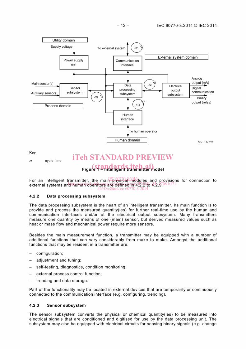
The generic transmitter model of Figure 1 gives a maximum configuration and is a tool for setting up a block scheme and concise description of the transmitter to be evaluated. It is also important for defining the functions to be considered in the performance tests (see Clause 5).
Functionally, a transmitter is an information transformer. Data enters and then exits the instrument through the various (external) domains given in Figure 1, following distinct data flow paths. The following paths can be defined, but are not always resident in a specific transmitter under consideration:
• Sensors (process domain) to external systems (remote data processing systems). • Sensors (process domain) to operator displays (human domain). • Sensors (process domain) to external systems (electrical outputs). • Operator commands through local keyboard (human domain) to data processing
subsystem, consequently affecting the above-mentioned data flows to external systems (remote data processing systems and electrical outputs).
• Remote commands (from external remote data processing systems) to the instrument’s data processing subsystem, consequently affecting the above-mentioned data flows to external systems (electrical outputs) and local operator displays (human domain).
A block scheme and description shall be included in the evaluation report and may be enhanced with photographs or drawings of important details.
iTeh STANDARD PREVIEW(standards.iteh.ai)
IEC 60770-3:2014https://standards.iteh.ai/catalog/standards/sist/5ff7d0d1-f3fb-4768-b171-
465f0ec8fae4/iec-60770-3-2014
– 12 – IEC 60770-3:2014 © IEC 2014
Data processing subsystem
Sensor subsystem
Power supply unit
Communication interface
Electrical output
subsystem
Human interface
ct1
ct2
ct4
ct3
Main sensor(s)
Auxiliary sensors
Supply voltage To external system
To human operator
Analog output (mA)
Human domain
Process domain
External system domain
Utility domain
Binary output (relay)
IEC 1827/14
Digital communication
Key
ct cycle time
Figure 1 – Intelligent transmitter model
For an intelligent transmitter, the main physical modules and provisions for connection to external systems and human operators are defined in 4.2.2 to 4.2.9.
4.2.2 Data processing subsystem
The data processing subsystem is the heart of an intelligent transmitter. Its main function is to provide and process the measured quantity(ies) for further real-time use by the human and communication interfaces and/or at the electrical output subsystem. Many transmitters measure one quantity by means of one (main) sensor, but derived measured values such as heat or mass flow and mechanical power require more sensors.
Besides the main measurement function, a transmitter may be equipped with a number of additional functions that can vary considerably from make to make. Amongst the additional functions that may be resident in a transmitter are:
– configuration; – adjustment and tuning; – self-testing, diagnostics, condition monitoring; – external process control function; – trending and data storage.
Part of the functionality may be located in external devices that are temporarily or continuously connected to the communication interface (e.g. configuring, trending).
4.2.3 Sensor subsystem
The sensor subsystem converts the physical or chemical quantity(ies) to be measured into electrical signals that are conditioned and digitised for use by the data processing unit. The subsystem may also be equipped with electrical circuits for sensing binary signals (e.g. change
iTeh STANDARD PREVIEW(standards.iteh.ai)
IEC 60770-3:2014https://standards.iteh.ai/catalog/standards/sist/5ff7d0d1-f3fb-4768-b171-
465f0ec8fae4/iec-60770-3-2014
IEC 60770-3:2014 © IEC 2014 – 13 –
measurement range on an external command), or auxiliary sensors of a different type (e.g. auxiliary for compensation or internal diagnostics and condition monitoring purposes).
The sensor and sensor subsystem may be integrated with the other modules in one enclosure. The sensor can also be located remotely (e.g. densitometer, thermocouple transmitter). Certain transmitters (e.g. thermocouple and resistance thermometer detector (RTD)) utilise standardised (third party) sensors that provide an electric signal. In such a case, it may be agreed to perform the evaluation with an acceptable simulator instead of the application of the actual quantity.
Depending on the measurement principle used, the sensor may not require auxiliary (external) power (e.g. thermocouples) or it may require auxiliary power (e.g. strain gauges) or a specifically characterised power source (e.g. electromagnetic and Coriolis flowmeters).
Sensors are, in general, incorporated in the process installations and in many cases, they may also be in direct contact with the process medium. As such, medium properties, medium conditions and installation conditions may adversely influence them. As a remote unit, the sensor may also be subjected to more severe environmental conditions than the other subsystems. Moreover, it shall also be considered whether it is necessary to apply combined environmental and process conditions during an evaluation.
As part of the design review, a list of the types of sensors that are provided and their measuring ranges shall be compiled.
4.2.4 Human interface
The human interface is an important tool for direct interaction and communication with the human operator. It consists of integral means at the instrument for reading out data (local display) and provisions for entering and requesting data (local pushbuttons). Instruments may be provided that are not equipped with a human interface. Access to the database is then provided via the communication interface and the external system or a handheld terminal.
A list of the measurement data that can be shown on the display and the refresh rates, as well as the status data that can either automatically or on request be made available to the operator shall be tabulated. In addition, a summary of the functions and facilities for access and data presentation shall be made.
4.2.5 Communication interface
Transmitter intelligence is supported by the communication interface, which connects the instrument to external systems. Through the interface (wired or wireless), measurement and control data are transferred and access is also provided to the instrument's configuration data. In the case of hybrid (SMART) instruments, the digital signal is superimposed on an analogue current signal and it is made available at the electrical output subsystem. There may be instruments which do not have a communication interface. Then configuration and read-out of data may take place via the human interface
A list of the measurement data that can be transferred to a host and the refresh rates should be compiled. A summary of the status data that can either automatically or on request be transferred to the host shall also be listed. The functions and facilities for access and data presentation shall also be indicated.
4.2.6 Electrical output subsystem
Instruments suitable for connection to a fieldbus (or wireless) need not necessarily be provided with an electrical output subsystem.
The electrical output subsystem primarily converts digital information provided by the data processing subsystem into one or more analogue electrical signals. It may also be equipped
iTeh STANDARD PREVIEW(standards.iteh.ai)
IEC 60770-3:2014https://standards.iteh.ai/catalog/standards/sist/5ff7d0d1-f3fb-4768-b171-
465f0ec8fae4/iec-60770-3-2014