Embed Size (px)
Citation preview
IEC 61936-1 Edition 2.0 2014-02
INTERNATIONAL STANDARD NORME INTERNATIONALE
Power installations exceeding 1 kV a.c. – Part 1: Common rules Installations électriques en courant alternatif de puissance supérieure à 1 kV – Partie 1: Règles communes
IEC
619
36-1
:201
0-08
/AM
D1:
2014
-02(
EN
-FR
)
®
AMENDMENT 1 AMENDEMENT 1
iTeh STANDARD PREVIEW(standards.iteh.ai)
IEC 61936-1:2010/AMD1:2014https://standards.iteh.ai/catalog/standards/sist/88ec161c-e156-4502-a162-
add454a2ae62/iec-61936-1-2010-amd1-2014
THIS PUBLICATION IS COPYRIGHT PROTECTED Copyright © 2014 IEC, Geneva, Switzerland All rights reserved. Unless otherwise specified, no part of this publication may be reproduced or utilized in any form or by any means, electronic or mechanical, including photocopying and microfilm, without permission in writing from either IEC or IEC's member National Committee in the country of the requester. If you have any questions about IEC copyright or have an enquiry about obtaining additional rights to this publication, please contact the address below or your local IEC member National Committee for further information. Droits de reproduction réservés. Sauf indication contraire, aucune partie de cette publication ne peut être reproduite ni utilisée sous quelque forme que ce soit et par aucun procédé, électronique ou mécanique, y compris la photocopie et les microfilms, sans l'accord écrit de l'IEC ou du Comité national de l'IEC du pays du demandeur. Si vous avez des questions sur le copyright de l'IEC ou si vous désirez obtenir des droits supplémentaires sur cette publication, utilisez les coordonnées ci-après ou contactez le Comité national de l'IEC de votre pays de résidence.
IEC Central Office Tel.: +41 22 919 02 11 3, rue de Varembé Fax: +41 22 919 03 00 CH-1211 Geneva 20 [email protected] Switzerland www.iec.ch
About the IEC The International Electrotechnical Commission (IEC) is the leading global organization that prepares and publishes International Standards for all electrical, electronic and related technologies. About IEC publications The technical content of IEC publications is kept under constant review by the IEC. Please make sure that you have the latest edition, a corrigenda or an amendment might have been published. IEC Catalogue - webstore.iec.ch/catalogue The stand-alone application for consulting the entire bibliographical information on IEC International Standards, Technical Specifications, Technical Reports and other documents. Available for PC, Mac OS, Android Tablets and iPad. IEC publications search - www.iec.ch/searchpub The advanced search enables to find IEC publications by a variety of criteria (reference number, text, technical committee,…). It also gives information on projects, replaced and withdrawn publications. IEC Just Published - webstore.iec.ch/justpublished Stay up to date on all new IEC publications. Just Published details all new publications released. Available online and also once a month by email.
Electropedia - www.electropedia.org The world's leading online dictionary of electronic and electrical terms containing more than 30 000 terms and definitions in English and French, with equivalent terms in 14 additional languages. Also known as the International Electrotechnical Vocabulary (IEV) online. IEC Glossary - std.iec.ch/glossary More than 55 000 electrotechnical terminology entries in English and French extracted from the Terms and Definitions clause of IEC publications issued since 2002. Some entries have been collected from earlier publications of IEC TC 37, 77, 86 and CISPR. IEC Customer Service Centre - webstore.iec.ch/csc If you wish to give us your feedback on this publication or need further assistance, please contact the Customer Service Centre: [email protected].
A propos de l'IEC La Commission Electrotechnique Internationale (IEC) est la première organisation mondiale qui élabore et publie des Normes internationales pour tout ce qui a trait à l'électricité, à l'électronique et aux technologies apparentées. A propos des publications IEC Le contenu technique des publications IEC est constamment revu. Veuillez vous assurer que vous possédez l’édition la plus récente, un corrigendum ou amendement peut avoir été publié. Catalogue IEC - webstore.iec.ch/catalogue Application autonome pour consulter tous les renseignements bibliographiques sur les Normes internationales, Spécifications techniques, Rapports techniques et autres documents de l'IEC. Disponible pour PC, Mac OS, tablettes Android et iPad. Recherche de publications IEC - www.iec.ch/searchpub La recherche avancée permet de trouver des publications IEC en utilisant différents critères (numéro de référence, texte, comité d’études,…). Elle donne aussi des informations sur les projets et les publications remplacées ou retirées. IEC Just Published - webstore.iec.ch/justpublished Restez informé sur les nouvelles publications IEC. Just Published détaille les nouvelles publications parues. Disponible en ligne et aussi une fois par mois par email.
Electropedia - www.electropedia.org Le premier dictionnaire en ligne de termes électroniques et électriques. Il contient plus de 30 000 termes et définitions en anglais et en français, ainsi que les termes équivalents dans 14 langues additionnelles. Egalement appelé Vocabulaire Electrotechnique International (IEV) en ligne. Glossaire IEC - std.iec.ch/glossary Plus de 55 000 entrées terminologiques électrotechniques, en anglais et en français, extraites des articles Termes et Définitions des publications IEC parues depuis 2002. Plus certaines entrées antérieures extraites des publications des CE 37, 77, 86 et CISPR de l'IEC. Service Clients - webstore.iec.ch/csc Si vous désirez nous donner des commentaires sur cette publication ou si vous avez des questions contactez-nous: [email protected].
iTeh STANDARD PREVIEW(standards.iteh.ai)
IEC 61936-1:2010/AMD1:2014https://standards.iteh.ai/catalog/standards/sist/88ec161c-e156-4502-a162-
add454a2ae62/iec-61936-1-2010-amd1-2014
IEC 61936-1 Edition 2.0 2014-02
INTERNATIONAL STANDARD NORME INTERNATIONALE
Power installations exceeding 1 kV a.c. – Part 1: Common rules Installations électriques en courant alternatif de puissance supérieure à 1 kV – Partie 1: Règles communes
INTERNATIONAL ELECTROTECHNICAL COMMISSION
COMMISSION ELECTROTECHNIQUE INTERNATIONALE R ICS 29.020; 29.080.01
PRICE CODE CODE PRIX
ISBN 978-2-8322-1384-1
® Registered trademark of the International Electrotechnical Commission Marque déposée de la Commission Electrotechnique Internationale
®
Warning! Make sure that you obtained this publication from an authorized distributor. Attention! Veuillez vous assurer que vous avez obtenu cette publication via un distributeur agréé.
AMENDMENT 1 AMENDEMENT 1
iTeh STANDARD PREVIEW(standards.iteh.ai)
IEC 61936-1:2010/AMD1:2014https://standards.iteh.ai/catalog/standards/sist/88ec161c-e156-4502-a162-
add454a2ae62/iec-61936-1-2010-amd1-2014
– 2 – 61936-1 Amend.1 © IEC:2014
FOREWORD
This amendment has been prepared by IEC technical committee 99: System engineering and erection of electrical power installations in systems with nominal voltages above 1 kV a.c. and 1,5 kV d.c., particularly concerning safety aspects.
The text of this amendment is based on the following documents:
FDIS Report on voting
99/129/FDIS 99/131/RVD
Full information on the voting for the approval of this amendment can be found in the report on voting indicated in the above table.
The committee has decided that the contents of this amendment and the base publication will remain unchanged until the stability date indicated on the IEC web site under "http://webstore.iec.ch" in the data related to the specific publication. At this date, the publication will be
• reconfirmed, • withdrawn, • replaced by a revised edition, or • amended.
_____________
Foreword
Insert, in the existing list of differences in some countries, the following new items: • 7.2.6: 50 mm × 200 mm mesh is not accepted (Australia)
• 7.2.6: Guidance regarding fence construction can be found at ENA Doc 015 (Australia)
• 8.7.1: Fire rating of barriers must be a minimum fire rating of 120 minutes (Australia)
• 8.7.2: The dimensions G1 and G2 are to be measured from the inside edge wall of any bund wall rather than the measured point shown in Figure 7a) and 7b) from the transformer where the bund wall is wider than the transformer (Australia)
• 8.8.1.3: Spill containment should extend by 50 % of the height of the transformer (Australia)
• Figure 7a): The dimensions G1 and G2 are to be measured from the inside edge wall of any bund wall rather than the measured point shown in Figure 7a) from the transformer where the bund wall is wider than the transformer (Australia)
• Figure 7b): The dimensions G1 and G2 are to be measured from the inside edge wall of any bund wall rather than the measured point shown in Figure 7b) from the transformer where the bund wall is wider than the transformer (Australia)
• Clause 10: For requirements regarding earthing refer to AS 2067, Substations and High Voltage Installations (Australia)
1 Scope
Add the following new item e) after d):
e) Electrical installations erected on offshore platforms e.g. offshore wind power farms.
iTeh STANDARD PREVIEW(standards.iteh.ai)
IEC 61936-1:2010/AMD1:2014https://standards.iteh.ai/catalog/standards/sist/88ec161c-e156-4502-a162-
add454a2ae62/iec-61936-1-2010-amd1-2014
61936-1 Amend.1 © IEC:2014 – 3 –
Modify the fifth dashed item in the last list of this clause as follows:
– installations on ships according to IEC 60092 [34] series and offshore units according to IEC 61892 [35] series, which are used in the offshore petroleum industry for drilling, processing and storage purposes.
Modify the first paragraph after the last list of this clause as follows:
This standard does not apply to the design of prefabricated, type-tested switchgear and high voltage/low voltage prefabricated substation, for which separate IEC standards exist.
2 Normative references
Add, to the existing list, the title of the following standards:
IEC/TS 61463, Bushings – Seismic qualification
IEC 62271-206, High-voltage switchgear and controlgear – Part 206: Voltage presence indicating systems for rated voltages above 1 kV and up to and including 52 kV
IEC 62271-207, High-voltage switchgear and controlgear – Part 207: Seismic qualification for gas-insulated switchgear assemblies for rated voltages above 52 kV
IEC/TR 62271-300, High-voltage switchgear and controlgear – Part 300: Seismic qualification of alternating current circuit-breakers
IEC 82079-1, Preparation of instructions for use – Structuring, content and presentation – Part 1: General principles and detailed requirements
Replace the reference to IEC 62271-1:2007 by the following new reference:
IEC 62271-1:2007, High-voltage switchgear and controlgear – Part 1: Common specifications Amendment 1:2011
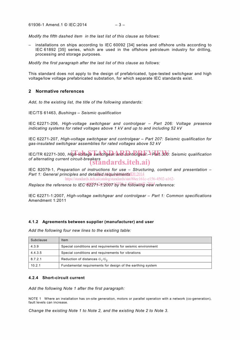
4.1.2 Agreements between supplier (manufacturer) and user
Add the following four new lines to the existing table:
Subclause Item
4.3.9 Special conditions and requirements for seismic environment
4.4.3.5 Special conditions and requirements for vibrations
8.7.2.1 Reduction of distances G1/G2
10.2.1 Fundamental requirements for design of the earthing system
4.2.4 Short-circuit current
Add the following Note 1 after the first paragraph:
NOTE 1 Where an installation has on-site generation, motors or parallel operation with a network (co-generation), fault levels can increase.
Change the existing Note 1 to Note 2, and the existing Note 2 to Note 3.
iTeh STANDARD PREVIEW(standards.iteh.ai)
IEC 61936-1:2010/AMD1:2014https://standards.iteh.ai/catalog/standards/sist/88ec161c-e156-4502-a162-
add454a2ae62/iec-61936-1-2010-amd1-2014
– 4 – 61936-1 Amend.1 © IEC:2014
4.2.7 Electric and magnetic fields
Modify the existing note as follows:
NOTE National and/or international regulations may specify acceptable levels. Further information is available from International Commission on Non-Ionizing Radiation Protection (ICNIRP) or IEEE.
4.3.1 Equipment and supporting structures
Replace the existing Note 1 by the following normal text:
Consideration shall be given to temporary stresses and loads that may be applied during construction or maintenance procedures. Specific equipment can be affected by cyclic loads and stresses due to thermal expansions (refer to specific equipment standards).
Delete Note 2.
Add, at the end of the second list, the following new item:
– seismic loads.
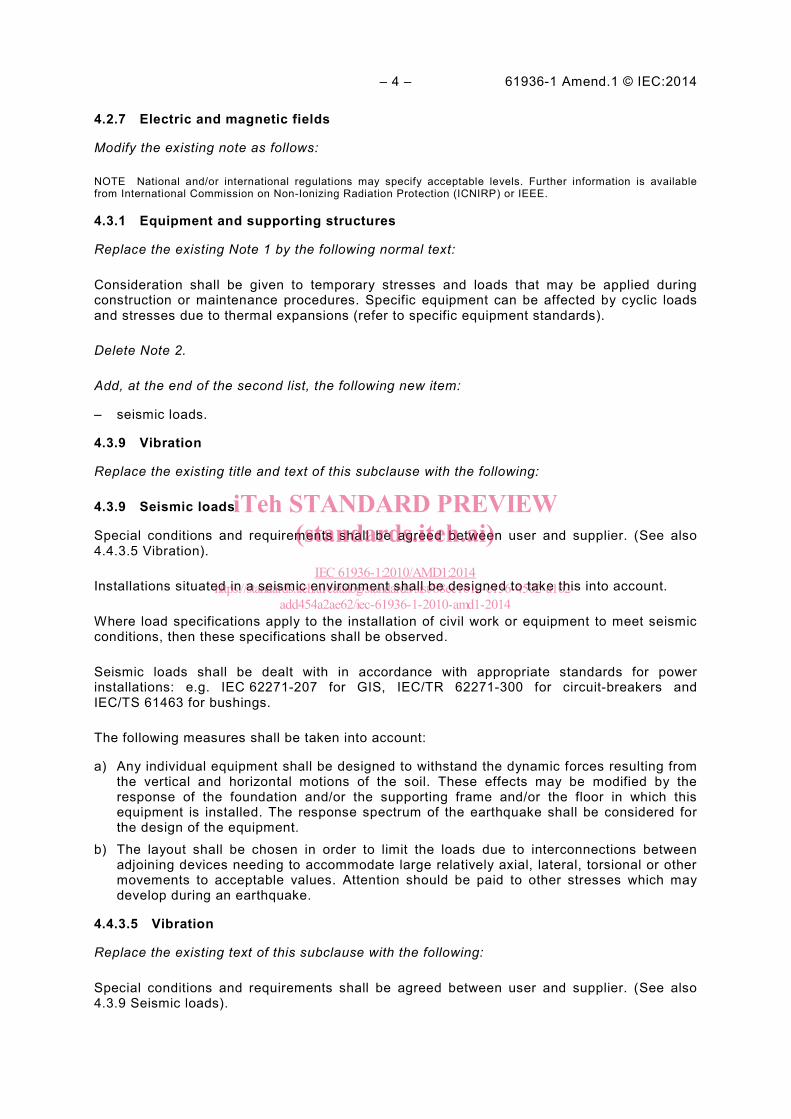
4.3.9 Vibration
Replace the existing title and text of this subclause with the following:
4.3.9 Seismic loads
Special conditions and requirements shall be agreed between user and supplier. (See also 4.4.3.5 Vibration).
Installations situated in a seismic environment shall be designed to take this into account.
Where load specifications apply to the installation of civil work or equipment to meet seismic conditions, then these specifications shall be observed.
Seismic loads shall be dealt with in accordance with appropriate standards for power installations: e.g. IEC 62271-207 for GIS, IEC/TR 62271-300 for circuit-breakers and IEC/TS 61463 for bushings.
The following measures shall be taken into account:
a) Any individual equipment shall be designed to withstand the dynamic forces resulting from the vertical and horizontal motions of the soil. These effects may be modified by the response of the foundation and/or the supporting frame and/or the floor in which this equipment is installed. The response spectrum of the earthquake shall be considered for the design of the equipment.
b) The layout shall be chosen in order to limit the loads due to interconnections between adjoining devices needing to accommodate large relatively axial, lateral, torsional or other movements to acceptable values. Attention should be paid to other stresses which may develop during an earthquake.
4.4.3.5 Vibration
Replace the existing text of this subclause with the following:
Special conditions and requirements shall be agreed between user and supplier. (See also 4.3.9 Seismic loads).
iTeh STANDARD PREVIEW(standards.iteh.ai)
IEC 61936-1:2010/AMD1:2014https://standards.iteh.ai/catalog/standards/sist/88ec161c-e156-4502-a162-
add454a2ae62/iec-61936-1-2010-amd1-2014
61936-1 Amend.1 © IEC:2014 – 5 –
Vibration caused by wind, electromagnetic stresses, traffic (e. g. temporary road and railway traffic) and industrial processes shall be considered. The withstand capability of equipment against vibrations shall be given by the manufacturer.
The service stresses of equipment, which may be transmitted through a common monolithic foundation or floor (for example opening/reclosing of circuit-breakers) shall be taken into account.
5.4.1 General
Replace the first sentence of the second paragraph with the following:
If parts of an installation can be separated from each other by a disconnector, these parts shall be tested at the rated impulse withstand voltage for the isolating distance (see Tables 1a and 1b as well as Tables 2a and 2b of IEC 62271-1:2007, Amendment 1:2011).
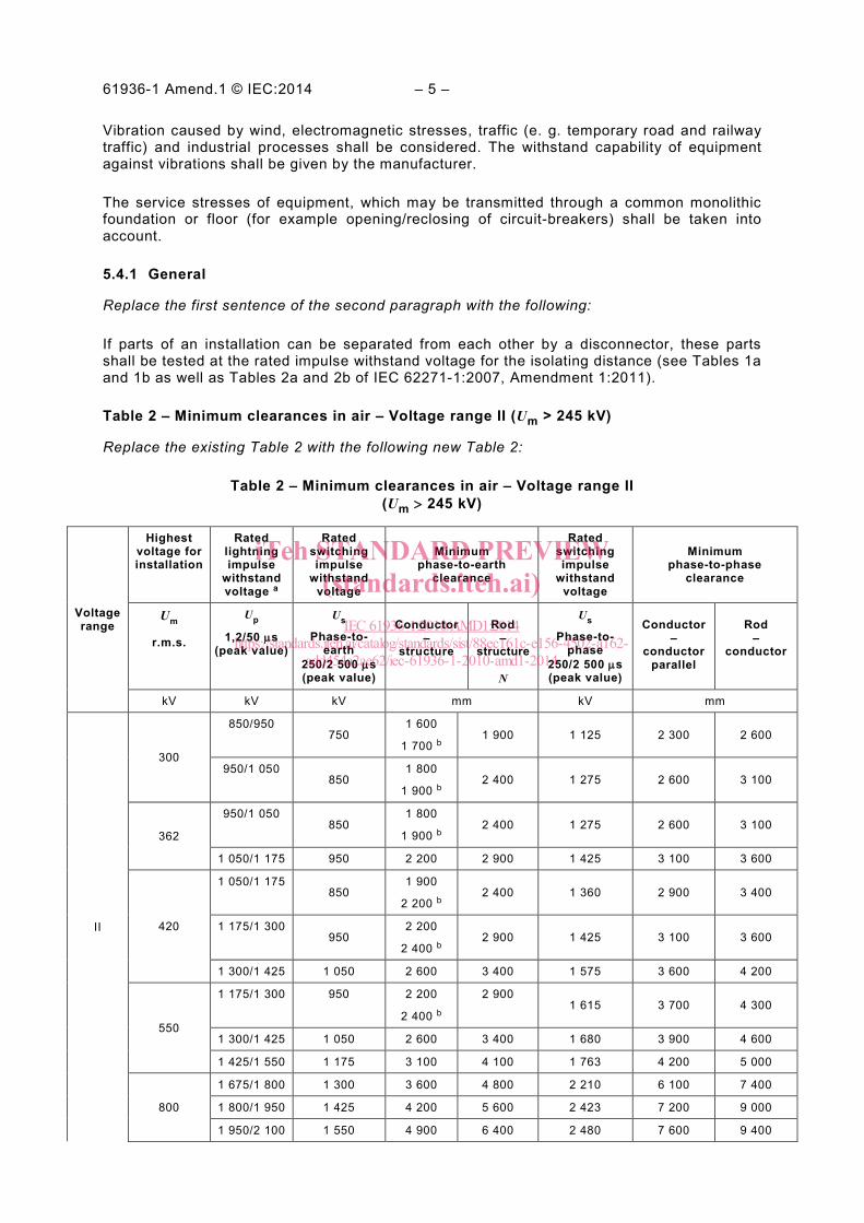
Table 2 – Minimum clearances in air – Voltage range II (Um > 245 kV)
Replace the existing Table 2 with the following new Table 2:
Table 2 – Minimum clearances in air – Voltage range II (Um > 245 kV)
Voltage range
Highest voltage for installation
Rated lightning impulse
withstand voltage a
Rated switching impulse
withstand voltage
Minimum phase-to-earth
clearance
Rated switching impulse
withstand voltage
Minimum phase-to-phase
clearance
Um
r.m.s.
Up
1,2/50 µs (peak value)
Us
Phase-to- earth
250/2 500 µs (peak value)
Conductor –
structure
Rod –
structure
N
Us
Phase-to-phase
250/2 500 µs (peak value)
Conductor –
conductor parallel
Rod –
conductor
kV kV kV mm kV mm
II
300
850/950 750
1 600
1 700 b 1 900 1 125 2 300 2 600
950/1 050 850
1 800
1 900 b 2 400 1 275 2 600 3 100
362
950/1 050 850
1 800
1 900 b 2 400 1 275 2 600 3 100
1 050/1 175 950 2 200 2 900 1 425 3 100 3 600
420
1 050/1 175 850
1 900
2 200 b 2 400 1 360 2 900 3 400
1 175/1 300 950
2 200
2 400 b 2 900 1 425 3 100 3 600
1 300/1 425 1 050 2 600 3 400 1 575 3 600 4 200
550
1 175/1 300 950 2 200
2 400 b
2 900 1 615 3 700 4 300
1 300/1 425 1 050 2 600 3 400 1 680 3 900 4 600
1 425/1 550 1 175 3 100 4 100 1 763 4 200 5 000
800
1 675/1 800 1 300 3 600 4 800 2 210 6 100 7 400
1 800/1 950 1 425 4 200 5 600 2 423 7 200 9 000
1 950/2 100 1 550 4 900 6 400 2 480 7 600 9 400
iTeh STANDARD PREVIEW(standards.iteh.ai)
IEC 61936-1:2010/AMD1:2014https://standards.iteh.ai/catalog/standards/sist/88ec161c-e156-4502-a162-
add454a2ae62/iec-61936-1-2010-amd1-2014
– 6 – 61936-1 Amend.1 © IEC:2014
Voltage range
Highest voltage for installation
Rated lightning impulse
withstand voltage a
Rated switching impulse
withstand voltage
Minimum phase-to-earth
clearance
Rated switching impulse
withstand voltage
Minimum phase-to-phase
clearance
Um
r.m.s.
Up
1,2/50 µs (peak value)
Us
Phase-to- earth
250/2 500 µs (peak value)
Conductor –
structure
Rod –
structure
N
Us
Phase-to-phase
250/2 500 µs (peak value)
Conductor –
conductor parallel
Rod –
conductor
kV kV kV mm kV mm
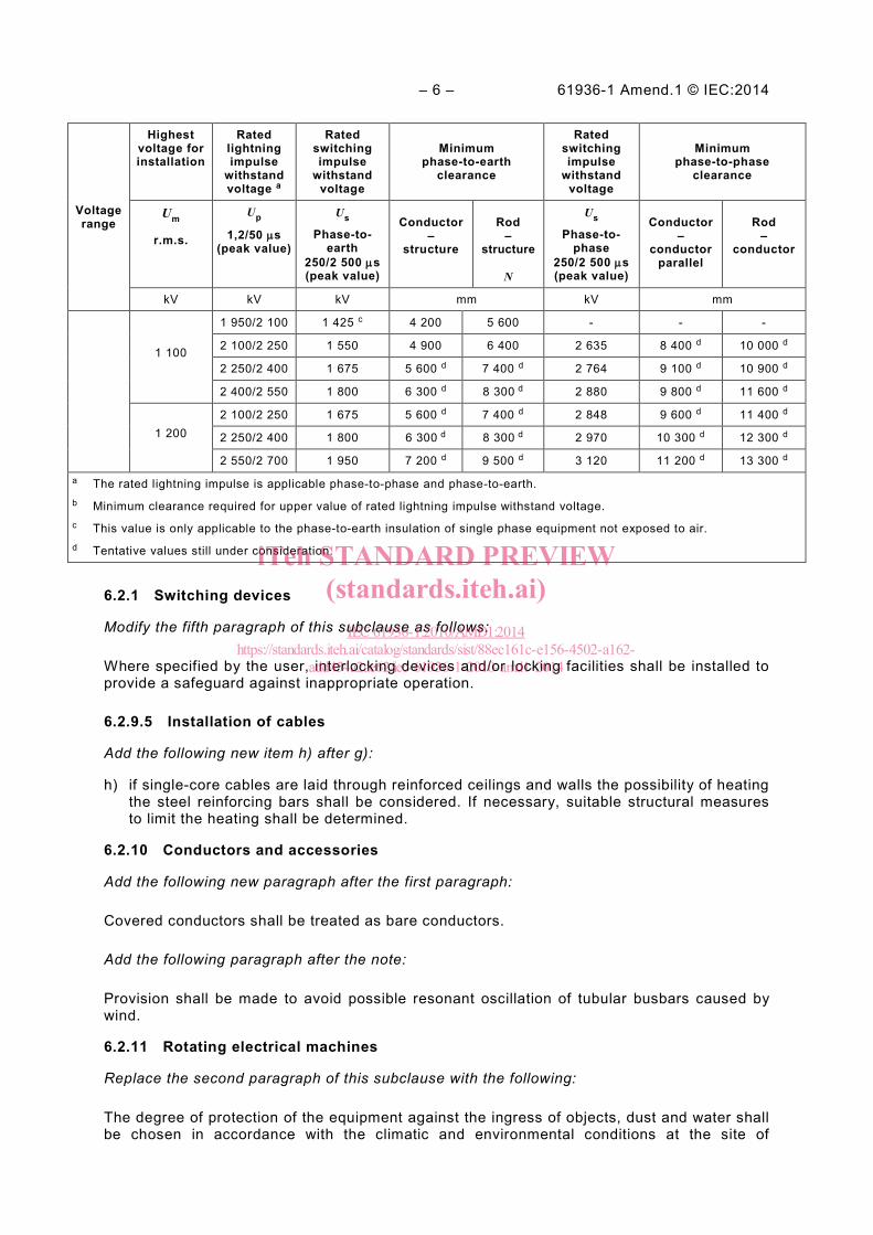
1 100
1 950/2 100 1 425 c 4 200 5 600 - - -
2 100/2 250 1 550 4 900 6 400 2 635 8 400 d 10 000 d
2 250/2 400 1 675 5 600 d 7 400 d 2 764 9 100 d 10 900 d
2 400/2 550 1 800 6 300 d 8 300 d 2 880 9 800 d 11 600 d
1 200 2 100/2 250 1 675 5 600 d 7 400 d 2 848 9 600 d 11 400 d
2 250/2 400 1 800 6 300 d 8 300 d 2 970 10 300 d 12 300 d
2 550/2 700 1 950 7 200 d 9 500 d 3 120 11 200 d 13 300 d a The rated lightning impulse is applicable phase-to-phase and phase-to-earth. b Minimum clearance required for upper value of rated lightning impulse withstand voltage. c This value is only applicable to the phase-to-earth insulation of single phase equipment not exposed to air. d Tentative values still under consideration.
6.2.1 Switching devices
Modify the fifth paragraph of this subclause as follows:
Where specified by the user, interlocking devices and/or locking facilities shall be installed to provide a safeguard against inappropriate operation.
6.2.9.5 Installation of cables
Add the following new item h) after g):
h) if single-core cables are laid through reinforced ceilings and walls the possibility of heating the steel reinforcing bars shall be considered. If necessary, suitable structural measures to limit the heating shall be determined.
6.2.10 Conductors and accessories
Add the following new paragraph after the first paragraph:
Covered conductors shall be treated as bare conductors.
Add the following paragraph after the note:
Provision shall be made to avoid possible resonant oscillation of tubular busbars caused by wind.
6.2.11 Rotating electrical machines
Replace the second paragraph of this subclause with the following:
The degree of protection of the equipment against the ingress of objects, dust and water shall be chosen in accordance with the climatic and environmental conditions at the site of
iTeh STANDARD PREVIEW(standards.iteh.ai)
IEC 61936-1:2010/AMD1:2014https://standards.iteh.ai/catalog/standards/sist/88ec161c-e156-4502-a162-
add454a2ae62/iec-61936-1-2010-amd1-2014
61936-1 Amend.1 © IEC:2014 – 7 –
installation. Hazardous parts of the machine shall be protected against accidental contact by persons. The degree of protection shall be defined in accordance with IEC 60529.
7.2.1 Protective barrier clearances
Replace the existing text of this subclause with the following:
Within an installation, the following minimum protective clearances shall be maintained between live parts and the internal surface of any protective barrier (see Figure 1):
– for solid walls, without openings, with a minimum height of 1 800 mm, the minimum protective barrier clearance is B1 = N;
– for wire meshes, screens or solid walls with openings, with a minimum height of 1 800 mm and a degree of protection of IPXXB (see IEC 60529), the minimum protective barrier clearance is B2 = N + 80 mm.
NOTE The degree IPXXB ensures protection against access to hazardous parts with fingers.
For non-rigid protective barriers and wire meshes, the clearance values shall be increased to take into account any possible displacement of the protective barrier or mesh.
7.2.6 External fences or walls and access doors
Add the following note after the last paragraph:
NOTE The use of metal mat fences with a mesh size of 50 mm x 200 mm (width x height) is applicable if the design of fencing prevents unauthorized entrance.
7.4.2.4 Earthing
Modify the first sentence of the second paragraph as follows:
The three enclosures of a single-phase type GIS shall be bonded together with short connections and earthed at least at the end of the enclosure of the outgoing and incoming feeders.
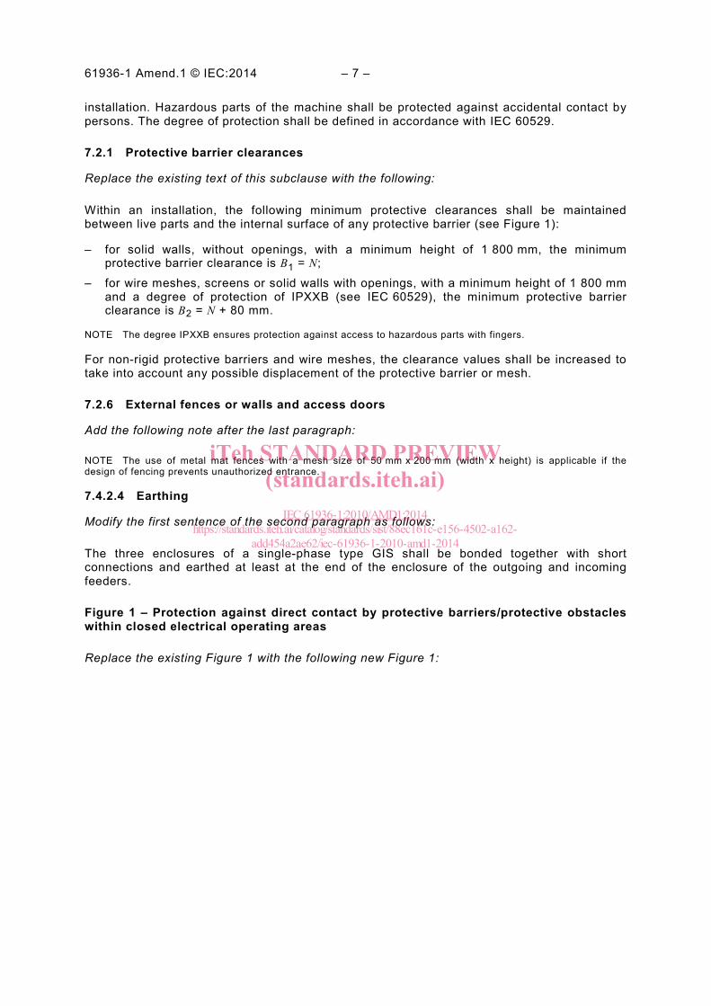
Figure 1 – Protection against direct contact by protective barriers/protective obstacles within closed electrical operating areas
Replace the existing Figure 1 with the following new Figure 1:
iTeh STANDARD PREVIEW(standards.iteh.ai)
IEC 61936-1:2010/AMD1:2014https://standards.iteh.ai/catalog/standards/sist/88ec161c-e156-4502-a162-
add454a2ae62/iec-61936-1-2010-amd1-2014
– 8 – 61936-1 Amend.1 © IEC:2014
Non-accessible surface inside a barrier or obstacle
Indoor: O1 = N + 200 (500 min.)Outdoor : O2 = N + 300 (600 min.)
Barrier less than 1 800 or rails, chains, ropes
1 80
0 m
in.
H =
N +
2 2
50 (
2 50
0 m
in.)
Accessible surface
Protective barrierH
= N
+ 2
250
(2
500
min
.)Protective obstacle
1 20
0 m
in.
1 40
0 m
ax.
2 25
0
B1 = N Solid walls without openings
B2 = N + 80 Wire mesh / Screen-IPXXB
N N
Dimensions in millimetres
Key
N Minimum clearance
O Obstacle clearance
B Barrier clearance
Figure 1 – Protection against direct contact by protective barriers/protective obstacles within closed electrical operating areas
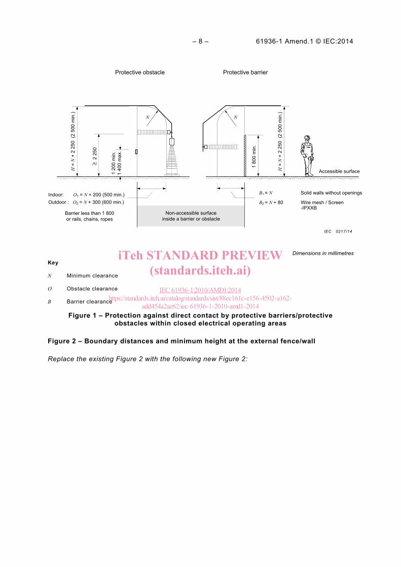
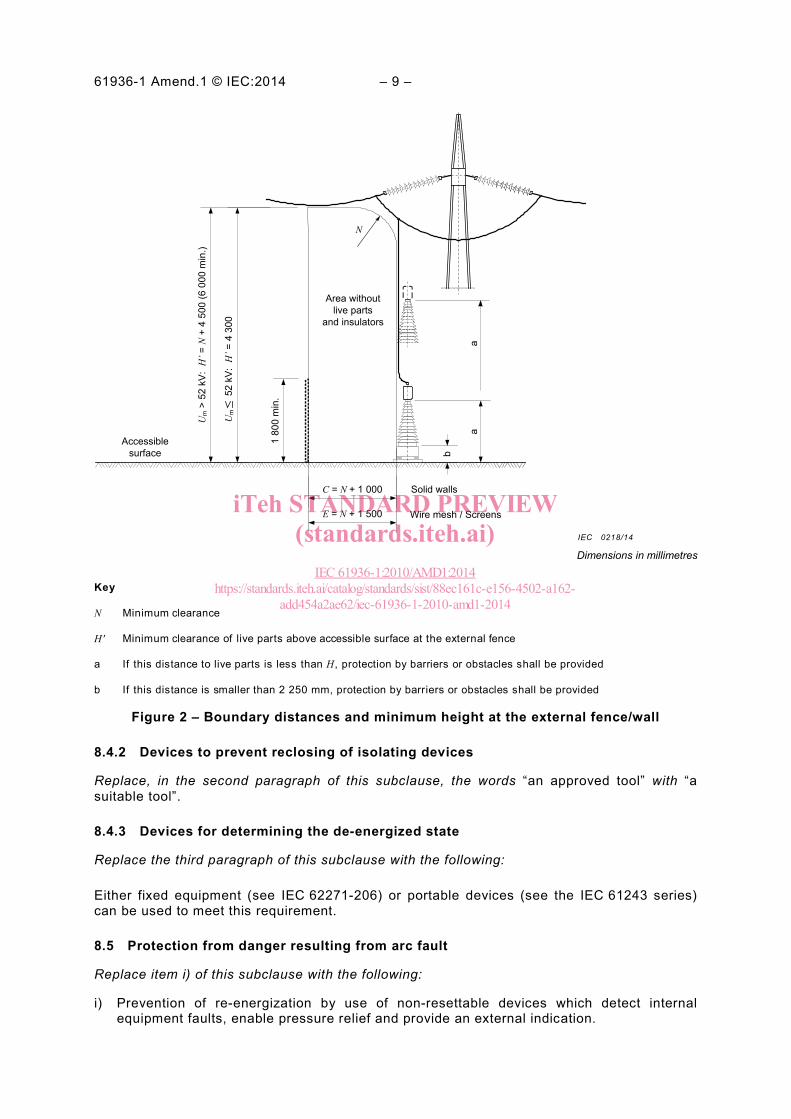
Figure 2 – Boundary distances and minimum height at the external fence/wall
Replace the existing Figure 2 with the following new Figure 2:
IEC 0217/14
iTeh STANDARD PREVIEW(standards.iteh.ai)
IEC 61936-1:2010/AMD1:2014https://standards.iteh.ai/catalog/standards/sist/88ec161c-e156-4502-a162-
add454a2ae62/iec-61936-1-2010-amd1-2014
61936-1 Amend.1 © IEC:2014 – 9 –
Accessible surface
1 80
0 m
in.
Um
52
kV:
H’=
4 3
00
Um >
52
kV:
H’=
N +
4 5
00 (6
000
min
.)
C = N + 1 000
E = N + 1 500
Solid walls
Wire mesh / Screens
b
aa
Area without live parts
and insulators
N
Dimensions in millimetres
Key
N Minimum clearance
H ' Minimum clearance of live parts above accessible surface at the external fence
a If this distance to live parts is les s than H , protection by barriers or obstacles s hall be provided
b If this dis tance is smaller than 2 250 mm, protection by barriers or obstacles s hall be provided
Figure 2 – Boundary distances and minimum height at the external fence/wall
8.4.2 Devices to prevent reclosing of isolating devices
Replace, in the second paragraph of this subclause, the words “an approved tool” with “a suitable tool”.
8.4.3 Devices for determining the de-energized state
Replace the third paragraph of this subclause with the following:
Either fixed equipment (see IEC 62271-206) or portable devices (see the IEC 61243 series) can be used to meet this requirement.
8.5 Protection from danger resulting from arc fault
Replace item i) of this subclause with the following:
i) Prevention of re-energization by use of non-resettable devices which detect internal equipment faults, enable pressure relief and provide an external indication.
IEC 0218/14
iTeh STANDARD PREVIEW(standards.iteh.ai)
IEC 61936-1:2010/AMD1:2014https://standards.iteh.ai/catalog/standards/sist/88ec161c-e156-4502-a162-
add454a2ae62/iec-61936-1-2010-amd1-2014
– 10 – 61936-1 Amend.1 © IEC:2014
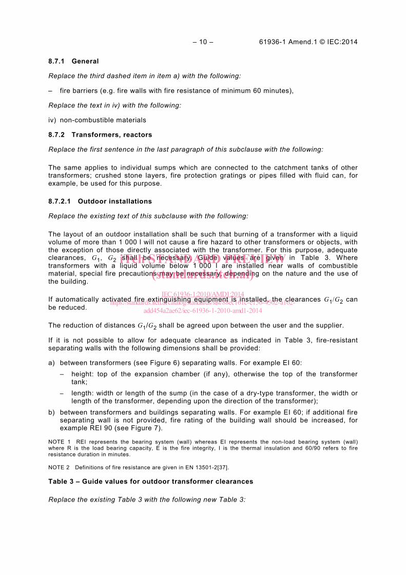
8.7.1 General
Replace the third dashed item in item a) with the following:
– fire barriers (e.g. fire walls with fire resistance of minimum 60 minutes),
Replace the text in iv) with the following:
iv) non-combustible materials
8.7.2 Transformers, reactors
Replace the first sentence in the last paragraph of this subclause with the following:
The same applies to individual sumps which are connected to the catchment tanks of other transformers; crushed stone layers, fire protection gratings or pipes filled with fluid can, for example, be used for this purpose.
8.7.2.1 Outdoor installations
Replace the existing text of this subclause with the following:
The layout of an outdoor installation shall be such that burning of a transformer with a liquid volume of more than 1 000 l will not cause a fire hazard to other transformers or objects, with the exception of those directly associated with the transformer. For this purpose, adequate clearances, G1, G2 shall be necessary. Guide values are given in Table 3. Where transformers with a liquid volume below 1 000 l are installed near walls of combustible material, special fire precautions may be necessary, depending on the nature and the use of the building.
If automatically activated fire extinguishing equipment is installed, the clearances G1/G2 can be reduced.
The reduction of distances G1/G2 shall be agreed upon between the user and the supplier.
If it is not possible to allow for adequate clearance as indicated in Table 3, fire-resistant separating walls with the following dimensions shall be provided:
a) between transformers (see Figure 6) separating walls. For example EI 60: – height: top of the expansion chamber (if any), otherwise the top of the transformer
tank; – length: width or length of the sump (in the case of a dry-type transformer, the width or
length of the transformer, depending upon the direction of the transformer); b) between transformers and buildings separating walls. For example EI 60; if additional fire
separating wall is not provided, fire rating of the building wall should be increased, for example REI 90 (see Figure 7).
NOTE 1 REI represents the bearing system (wall) whereas EI represents the non-load bearing system (wall) where R is the load bearing capacity, E is the fire integrity, I is the thermal insulation and 60/90 refers to fire resistance duration in minutes.
NOTE 2 Definitions of fire resistance are given in EN 13501-2[37].
Table 3 – Guide values for outdoor transformer clearances
Replace the existing Table 3 with the following new Table 3:
iTeh STANDARD PREVIEW(standards.iteh.ai)
IEC 61936-1:2010/AMD1:2014https://standards.iteh.ai/catalog/standards/sist/88ec161c-e156-4502-a162-
add454a2ae62/iec-61936-1-2010-amd1-2014
61936-1 Amend.1 © IEC:2014 – 11 –
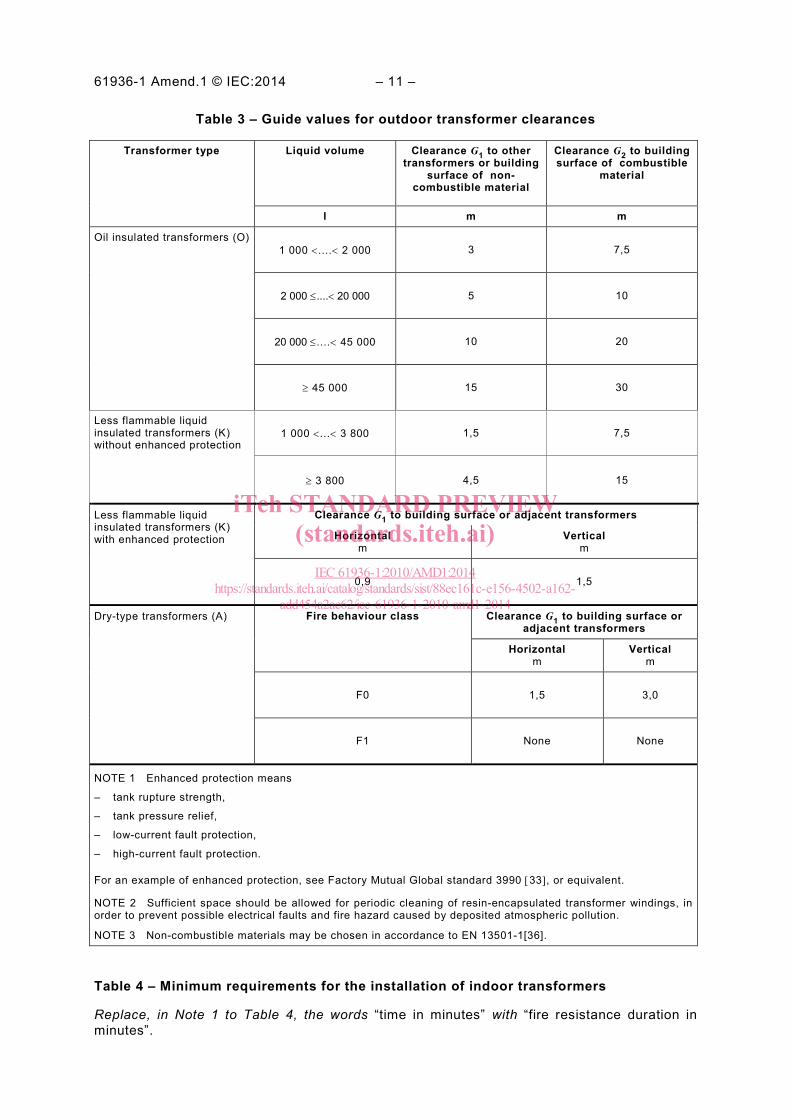
Table 3 – Guide values for outdoor transformer clearances
Transformer type Liquid volume Clearance G1 to other transformers or building
surface of non-combustible material
Clearance G2 to building surface of combustible
material
l m m
Oil insulated transformers (O) 1 000 <....< 2 000 3 7,5
2 000 ≤....< 20 000 5 10
20 000 ≤....< 45 000 10 20
≥ 45 000 15 30
Less flammable liquid insulated transformers (K) without enhanced protection
1 000 <...< 3 800 1,5 7,5
≥ 3 800 4,5 15
Less flammable liquid insulated transformers (K) with enhanced protection
Clearance G1 to building surface or adjacent transformers
Horizontal m
Vertical m
0,9 1,5
Dry-type transformers (A) Fire behaviour class Clearance G1 to building surface or adjacent transformers
Horizontal m
Vertical m
F0 1,5 3,0
F1 None None
NOTE 1 Enhanced protection means
– tank rupture strength,
– tank pressure relief,
– low-current fault protection,
– high-current fault protection.
For an example of enhanced protection, see Factory Mutual Global standard 3990 [33], or equivalent.
NOTE 2 Sufficient space should be allowed for periodic cleaning of resin-encapsulated transformer windings, in order to prevent possible electrical faults and fire hazard caused by deposited atmospheric pollution.
NOTE 3 Non-combustible materials may be chosen in accordance to EN 13501-1[36].
Table 4 – Minimum requirements for the installation of indoor transformers
Replace, in Note 1 to Table 4, the words “time in minutes” with “fire resistance duration in minutes”.
iTeh STANDARD PREVIEW(standards.iteh.ai)
IEC 61936-1:2010/AMD1:2014https://standards.iteh.ai/catalog/standards/sist/88ec161c-e156-4502-a162-
add454a2ae62/iec-61936-1-2010-amd1-2014