Embed Size (px)
Citation preview
> >
Your pipeline to the future!HOW TO ORDER
Series Code BodyMaterial Code Stem
Material Code DiscMaterial Code Seat
Material Code Actuator Code
200 PSIWafer Type BF75 Cast Iron * CI Stainless Steel *
Type 410 R Nickle Plated *Ductile Iron D Buna-N * B Bare Stem O
200 PSILug Type BF76 Ductile Iron * DI Stainless Steel
Type 316 S Aluminum *Bronze B EPDM * E 10 Position
Handle L
200 PSILug TypeDead End Service
BF76D
Carbon Steel CS Stainless Steel *Type 316 S Viton V Infinite
Handle I
Stainless Steel SS Special X Teflon T Gear Operator G
Notes:1. Not all configurations are readily available. Please contact factory. (*) Denotes standard materials.2. Other seat materials can be provided. Please contact factory.3. Other body materials can be provided. Please contact factory.
Special X Chain Wheel C
Actuated A
ORDERING EXAMPLE:
PART NUMBER: 8.0-BF75-CI-S-B-B-GDESCRIPTION: 8" Wafer Style Butterfly Valve, Cast Iron Body, 410 Stainless Steel Stem, Bronze Disc, Buna-N Seat, and Gear Operator
Flange Bolting Information
WAFER STYLE FLANGE BOLT DATA (1)
Valve Size QuantityPer Valve
BoltSize
Stud BoltLength "A"
2 4 5/8" - 11 4.75
2.5 4 5/8" - 11 5.25
3 4 5/8" - 11 5.25
4 8 5/8" - 11 5.5
5 8 3/4" - 10 6
6 8 3/4" - 10 6
8 8 3/4" - 10 6.5
10 12 7/8" - 9 7
12 12 7/8" - 9 7.75
14 12 1" - 8 8.25
16 16 1" - 8 8.75
18 16 1 1/8" - 7 10
20 20 1 1/8" - 7 11
24 20 1 1/4" - 7 12.75
1.FlangeboltinginformationisinaccordancewithASME16.5Class150specifications.
LUG STYLE FLANGE BOLT DATA (1)
Valve Size QuantityPer Valve
BoltSize
Cap ScrewLength "B"
2 8 5/8" - 11 1.25
2.5 8 5/8" - 11 1.5
3 8 5/8" - 11 1.5
4 16 5/8" - 11 1.75
5 16 3/4" - 10 1.75
6 16 3/4" - 10 1.75
8 16 3/4" - 10 2
10 24 7/8" - 9 2.25
12 24 7/8" - 9 2.5
14 24 1" - 8 2.75
16 32 1" - 8 3
18 32 1 1/8" - 7 3.5
20 40 1 1/8" - 7 4
24 40 1 1/4" - 7 4.75
1.FlangeboltinginformationisinaccordancewithASME16.5Class150specifications.
Wafer Body
Studs & Nuts
A
B
Threaded Studs
Cap Screw
Lug Body
Cap Screws
Titan Flow Control > Ordering and Installation
> 290 Corporate Drive > Lumberton, NC 28358 > 910-735-0000 T > 910-738-3848 F
®
TITAN [email protected]
7
FLOW SOLUTIONS INTERNATIONAL
SD SERIESSUCTION DIFFUSERS
FSI SD Series suction diffusersincrease the flow-straighteningcapablities and provide optimumflow condition at the pump inletswhile reducing the space and fittingrequirements.
It also eliminates the need for an equivalent length of ten pipe diameters of straight run ...
●
● Designed and manufactured in accordance withASME B31.1, ASME B31.3 and/or ASMESection VIII, Div. 1
● CRN available in all Provinces
● Welders certified to ASME Section IX
APPLICATION
APPLICABLE CODES
● Strainer, flow straightener, elbow and pipe reducerfor pump applications
● Standard and custom engineered designs● Integral straightening vanes reduce turbulence to
improve pump efficiency● One, three or five pipe diameters of flow straightening
(Type 1, 2 or 3)● Standard, undersized or oversized outlet connections● Direct mount to the suction side of a pump in either
horizontal or vertical position● Supporting pads for easy mounting of standard I.D.
support foot● Drain connection with plug furnished as standard
FEATURES-50 50 350150 250
Temperature (F)
Pre
ssu
re (
psi
g)
300
250
200
150
100
50
0450 550 650 750 850
Carbon Steel 150#
PRESSURE/TEMPERATURE CHARTASME B16.5
Contact Factory for higher ratings.
● Type 1 - One pipe diameter of flow straightening● Type 2 - Three pipe diameters of flow straightening● Type 3 - Five pipe diameters of flow straightening
● Customer specified materials, sizes and designs● Other flow straightening quality designs● Hinged or quick opening/operator assisted covers● Vent and/or differential pressure connections● ASME “U” stamped vessels on request● Other perforated screen and mesh liner baskets● Data Packages and MTR’s available on request
MODELS AVAILABLE
OPTIONS
5850 DON MURIE STREET, NIAGARA FALLS, ONTARIO L2E6X8, CANADA
TOLLFREE: 1-855-788-2468, INT'L: +905-330-3490, FAX: +1-905-248-3177
Hydronic Cooling & Heating andIndustrial Pumping
> 3725 WALDEN AVE, SUITE 18, LANCASTER, NEW YORK 14086. USA. TEL: +1-716-989-0076,1-716-343-3423
Edited with the trial version of Foxit Advanced PDF Editor
To remove this notice, visit:www.foxitsoftware.com/shopping
Save money and extend the life of system pumps, piping and components with FSI SD Series suction diffusers.
The FSI SD Series suction diffuser is designed and fabricated to the ASME Boiler & Pressure Vessel Code,
Section VIII, Division I.
Butterfly Valve Seating and Unseating Valve Torque Ratings Valve Sizes Full Rated Pressure Ratings (Torque for psi is expressed as in-lb, Torque for MPa is expressed as N-m) Correction
Factorsin mm 50 psi 0.4 MPa 100 psi 0.6 MPa 150 psi 1.0 MPa 200 psi 1.4 MPa 250 psi 1.6 MPa2 50 99 10 105 14 111 14 117 13 121 15 The following guidelines
may be used to estimate torque values for other
types of service.
For Dry Service:Multiply by 160%
For Lubricated Service:Multiply by 85%
For Actuator Sizing:First apply the correction
factor for the type of service then use the additional correction
factors
Multiply by 150%(Single Valve Application)
Multiply by 200%(Three way applications)
2.5 65 150 15 163 21 175 23 189 21 196 243 80 206 20 219 28 232 30 243 27 250 304 100 289 28 322 42 357 46 389 43 410 505 125 422 41 481 62 540 70 597 66 643 786 150 598 58 690 90 782 102 874 97 935 1148 200 1059 103 1182 154 1306 170 1429 159 1517 185
10 250 1670 163 1872 243 2074 269 2275 253 2403 29212 300 2568 250 2794 363 3023 392 3248 361 3401 41414 350 2639 257 3069 399 3500 454 3964 441 4267 51916 400 4260 415 4879 634 5500 714 5987 666 6280 76418 450 6287 612 7243 940 8199 1065 9183 1022 9817 119520 500 8360 814 9180 1192 10000 1298 10859 1208 11409 138924 600 15427 1502 16813 2183 18200 2363 18728 2084 19155 233230 750 27313 2660 29407 3818 31500 4090 33530 3731 34844 424136 900 54667 5323 57034 7405 59399 7712 61793 6877 63351 771142 1050 82460 8030 86034 11170 89600 11633 - - - - - - - - - - - -48 1200 108015 10518 112704 14633 117376 15239 122101 13588 125177 15236
The above torques are for reference only. They were calculated from test data using clean, wet fluids (i.e. water) at ambient temperatures during on/off service. During actual service, hydrodynamic torque may meet or exceed the above listed seating and unseating torques. Therefore, hydrodynamic torque must be considered during system design to ensure proper valve and actuator selection. As always, a Titan FCI application engineer is ready to assist with valve and actuator selection.
Butterfly Valve Cv Flow Coefficient Values (GPM @ 1ΔP)Valves Sizes Angle of Valve Disc Rotation
in mm 10° 20° 30° 40° 50° 60° 70° 80° 90°2 50 0.06 3 7 15 27 44 70 105 115
2.5 65 0.10 6 12 25 45 75 119 178 1963 80 0.20 9 18 39 70 116 183 275 3024 100 0.30 17 36 78 139 230 364 546 6005 125 0.50 29 61 133 237 392 620 930 10226 150 0.80 45 95 205 366 605 958 1437 15798 200 2 89 188 408 727 1202 1903 2854 3136
10 250 3 151 320 694 1237 2049 3240 4859 534012 300 4 234 495 1072 1911 3162 5005 7507 825014 350 6 338 715 1549 2761 4568 7230 10844 1191716 400 8 464 983 2130 3797 6282 9942 14913 1638818 450 11 615 1302 2822 5028 8320 13168 19752 2170520 500 14 791 1647 3628 6465 10698 16931 25396 2790824 600 22 1222 2587 5605 9989 16528 26157 39236 4311630 750 37 2080 4406 9546 17010 28147 44545 66818 7324636 900 260 3050 6730 12740 20220 32500 52500 79600 8750040 1000 313 3665 8089 15942 2429 39056 63093 95660 10515442 1050 350 4095 9040 17108 27150 43640 70500 106890 11750048 1200 455 5365 11840 22400 30600 51200 92300 140000 154000
This chart can be used as a guide only due to the numerous variations of flow conditions that may occur during actual service.
Flow Rate Limits (On/Off Service)
Fluids 20 ft/sec 6 m/sec
Gases 175 ft/sec 54 m/sec
This table lists velocity limits for on/off services only. Additionally, for throttling service, the flow velocity should not exceed 20 ft/sec for liquids and 175 ft/sec for gases.
Seat Material Temperature Ratings
Buna-N +10 ~ 180 °F -12 ~ 82 °C
EPDM -30 ~ 225 °F -34 ~107 °C
This table lists the theoretical temperature limits for elastomers. During actual service, hardening of the elastomer may cause the torque to exceed the structural limits of the valve.
Pressure Ratings (Bidirectional)
2" ~ 12" 200 psig 14 bar
14" ~ 24" 150 psig 10 bar
Butterfly Valve is mated between two flanges for bidirectional service and the disc is in the closed position.
Pressure Ratings (Dead-End)
2" ~ 12" 150 psig 10 bar
14" ~ 24" 100 psig 7 bar
Butterfly Valve is installed for dead-end service without a downstream flange. Disc is in the closed position. Please note, standard valves are not designed for dead-end service. Dead-end service must be specified by the customer.
Cv = FlowCoefficient
Q = SpecificGravityofliquidat60°FG = FlowrateinU.S.gallonsperminute(GPM)
ΔP= Pressuredropinpoundspersquareinch(PSI)
C = Q v *G P
Cv Equation For Liquids
The Flow Coefficient (designated as Cv) is a physical measurement that specifies the number of gallons per minute (GPM) that can pass through a piping component, at room temperature, and create a one (1) psi differential (ΔP) across the piping component.
Titan Flow Control > Engineering & Technical Data
> 290 Corporate Drive > Lumberton, NC 28358 > 910-735-0000 T > 910-738-3848 F
®
TITAN [email protected]
FSI - SD SERIES SUCTION DIFFUSER > Engineering & Technical Data 6
Model - Position 1 - 3SD1 – Type 1 – Standard OutletSD2 – Type 1 – Undersized OutletSD3 – Type 1 – Oversized OutletSD4 – Type 2 – Standard OutletSD5– Type 2 – Undersized OutletSD6– Type 2– Oversized OutletSD7 – Type 3 – Standard OutletSD8 – Type 3 – Undersized OutletSD9 – Type 3– Oversized OutletSDX – Custom Configuration
Material - Position 4C - Carbon SteelL - Low Temp CSV - 304 SST - 316 SSM - MonelX- Other
Inlet Size - Position 5B - 10C - 12D - 14E - 16F - 18G - 20H - 24J - 28K - 30
S D 1 C H 1 R - Q 4 2
ORDERING CODE
1 2 3 4 5 6 7 8 9 10 11
Model Material Inlet Class Con- Dash Cover Perf. MeshSize nections
L - 36M - 40N - 42X - OTHER
Class - Position 61 - 1503 - 3006 - 600X - Other
Connection - InletPosition 7F - Flat Face FlangeJ - Ring JointR - Raised Face FlangeX - Other
Dash - Position 8
Cover - Position 9B - Bolted & HingedC - Bolted & DavitD - Q.Open/Davit 1
Q - Q.Open/HingedX - Other
Perf. - Position 10304SS Material
A - NoneB - 3/64"1 - 1/32"2 - 1/16"3 - 3/32"4 - 1/8"
Mesh - Position 11A - None1 - 102 - 203 - 304 - 405 - 50
6 - 607 - 808 - 1009 - 120X - Other
Standard Outlet is one size smallerthan the inlet.Undersized Outlet is two sizessmaller than the linlet.Oversized Outlet is the same sizeas the inlet.
5 - 5/32"6 - 3/16"7 - 7/32"8 - 1/4"9 - 3/8"X - Other
SHELL
NOZZLES
FLANGES
HEADS
COUPLING
PLUG
BASKET
GASKET
STUD
NUT
A53 E/B/A106-B
A53 E/B/A106-B
A105
A516-70
A105
A105
304 SS
304 SS SPIRAL WOUND
A193-B7
A194-2H
A312
A312
A182
A240
A182
A182
304 SS
304 SS SPIRAL WOUND
A193-B8-1
A194-8
CARBON STEEL STAINLESS STEEL
DESCRIPTION SPECIFICATIONS
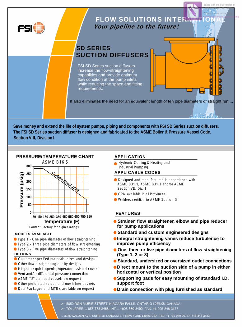
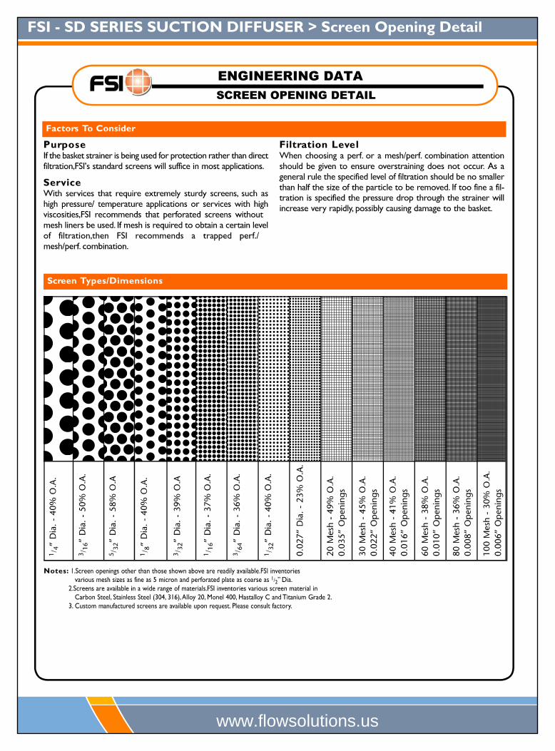
PARTS LIST AND STANDARD MATERIALS OPEN AREA RATIOSwith Standard Perforated Screen
Opening 40%, 1/8" Diameter
Nominal Gross Free OpenOutlet Screen Screen Area SizeArea Area Area Ratio
Inlet X Outlet (in2) (in2) (in2) (OAR)
10 x 6 28.89 455 182 6.3
10 x 8 50.03 455 182 3.6
10 x 10 78.85 700 280 3.6
12 x 8 50.03 524 210 4.2
12 x 10 78.85 700 280 3.6
12 x 12 113.10 811 324 2.9
14 x 10 78.85 700 280 3.6
14 x 12 113.10 811 324 2.9
14 x 14 137.89 1162 465 3.4
16 x 12 113.10 811 324 2.9
16 x 14 137.89 1162 465 3.4
16 x 16 182.65 1275 510 2.8
18 x 14 137.89 1162 465 3.4
18 x 16 182.65 1275 510 2.8
18 x 18 233.71 1470 588 2.5
20 x 16 182.65 1275 510 2.8
20 x 18 233.71 1470 588 2.5
20 x 20 291.04 2454 982 3.4
24 x 18 233.71 1470 588 2.5
24 x 20 291.04 2454 982 3.4
24 x 24 424.56 2454 982 2.3
OAR = Free Screen Area divided by Nominal Outlet Area.Free Screen Area = Opening % times Gross Screen Area.Values shown are approximate. Contact factory for exact ratios.
STANDARDSIZE SCREEN MATERIALS
All 1/8" Perf. 304 SS
SCREEN OPENINGS
Connections: 10" x 6" – 24" x 24" RF Inlet x FF Outlet
FLOW SOLUTIONS INTERNATIONAL INCwww.flowsolutions.us
(TYPE 1)
Butterfly Valve Seating and Unseating Valve Torque Ratings Valve Sizes Full Rated Pressure Ratings (Torque for psi is expressed as in-lb, Torque for MPa is expressed as N-m) Correction
Factorsin mm 50 psi 0.4 MPa 100 psi 0.6 MPa 150 psi 1.0 MPa 200 psi 1.4 MPa 250 psi 1.6 MPa2 50 99 10 105 14 111 14 117 13 121 15 The following guidelines
may be used to estimate torque values for other
types of service.
For Dry Service:Multiply by 160%
For Lubricated Service:Multiply by 85%
For Actuator Sizing:First apply the correction
factor for the type of service then use the additional correction
factors
Multiply by 150%(Single Valve Application)
Multiply by 200%(Three way applications)
2.5 65 150 15 163 21 175 23 189 21 196 243 80 206 20 219 28 232 30 243 27 250 304 100 289 28 322 42 357 46 389 43 410 505 125 422 41 481 62 540 70 597 66 643 786 150 598 58 690 90 782 102 874 97 935 1148 200 1059 103 1182 154 1306 170 1429 159 1517 185
10 250 1670 163 1872 243 2074 269 2275 253 2403 29212 300 2568 250 2794 363 3023 392 3248 361 3401 41414 350 2639 257 3069 399 3500 454 3964 441 4267 51916 400 4260 415 4879 634 5500 714 5987 666 6280 76418 450 6287 612 7243 940 8199 1065 9183 1022 9817 119520 500 8360 814 9180 1192 10000 1298 10859 1208 11409 138924 600 15427 1502 16813 2183 18200 2363 18728 2084 19155 233230 750 27313 2660 29407 3818 31500 4090 33530 3731 34844 424136 900 54667 5323 57034 7405 59399 7712 61793 6877 63351 771142 1050 82460 8030 86034 11170 89600 11633 - - - - - - - - - - - -48 1200 108015 10518 112704 14633 117376 15239 122101 13588 125177 15236
The above torques are for reference only. They were calculated from test data using clean, wet fluids (i.e. water) at ambient temperatures during on/off service. During actual service, hydrodynamic torque may meet or exceed the above listed seating and unseating torques. Therefore, hydrodynamic torque must be considered during system design to ensure proper valve and actuator selection. As always, a Titan FCI application engineer is ready to assist with valve and actuator selection.
Butterfly Valve Cv Flow Coefficient Values (GPM @ 1ΔP)Valves Sizes Angle of Valve Disc Rotation
in mm 10° 20° 30° 40° 50° 60° 70° 80° 90°2 50 0.06 3 7 15 27 44 70 105 115
2.5 65 0.10 6 12 25 45 75 119 178 1963 80 0.20 9 18 39 70 116 183 275 3024 100 0.30 17 36 78 139 230 364 546 6005 125 0.50 29 61 133 237 392 620 930 10226 150 0.80 45 95 205 366 605 958 1437 15798 200 2 89 188 408 727 1202 1903 2854 3136
10 250 3 151 320 694 1237 2049 3240 4859 534012 300 4 234 495 1072 1911 3162 5005 7507 825014 350 6 338 715 1549 2761 4568 7230 10844 1191716 400 8 464 983 2130 3797 6282 9942 14913 1638818 450 11 615 1302 2822 5028 8320 13168 19752 2170520 500 14 791 1647 3628 6465 10698 16931 25396 2790824 600 22 1222 2587 5605 9989 16528 26157 39236 4311630 750 37 2080 4406 9546 17010 28147 44545 66818 7324636 900 260 3050 6730 12740 20220 32500 52500 79600 8750040 1000 313 3665 8089 15942 2429 39056 63093 95660 10515442 1050 350 4095 9040 17108 27150 43640 70500 106890 11750048 1200 455 5365 11840 22400 30600 51200 92300 140000 154000
This chart can be used as a guide only due to the numerous variations of flow conditions that may occur during actual service.
Flow Rate Limits (On/Off Service)
Fluids 20 ft/sec 6 m/sec
Gases 175 ft/sec 54 m/sec
This table lists velocity limits for on/off services only. Additionally, for throttling service, the flow velocity should not exceed 20 ft/sec for liquids and 175 ft/sec for gases.
Seat Material Temperature Ratings
Buna-N +10 ~ 180 °F -12 ~ 82 °C
EPDM -30 ~ 225 °F -34 ~107 °C
This table lists the theoretical temperature limits for elastomers. During actual service, hardening of the elastomer may cause the torque to exceed the structural limits of the valve.
Pressure Ratings (Bidirectional)
2" ~ 12" 200 psig 14 bar
14" ~ 24" 150 psig 10 bar
Butterfly Valve is mated between two flanges for bidirectional service and the disc is in the closed position.
Pressure Ratings (Dead-End)
2" ~ 12" 150 psig 10 bar
14" ~ 24" 100 psig 7 bar
Butterfly Valve is installed for dead-end service without a downstream flange. Disc is in the closed position. Please note, standard valves are not designed for dead-end service. Dead-end service must be specified by the customer.
Cv = FlowCoefficient
Q = SpecificGravityofliquidat60°FG = FlowrateinU.S.gallonsperminute(GPM)
ΔP= Pressuredropinpoundspersquareinch(PSI)
C = Q v *G P
Cv Equation For Liquids
The Flow Coefficient (designated as Cv) is a physical measurement that specifies the number of gallons per minute (GPM) that can pass through a piping component, at room temperature, and create a one (1) psi differential (ΔP) across the piping component.
Titan Flow Control > Engineering & Technical Data
> 290 Corporate Drive > Lumberton, NC 28358 > 910-735-0000 T > 910-738-3848 F
®
TITAN [email protected]
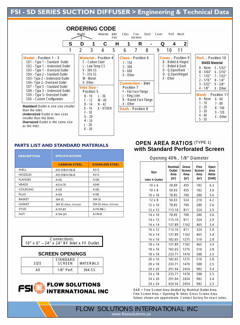
FSI - SD SERIES SUCTION DIFFUSER > Dimensional Data 6
A
B
C
D
E
OUTLET
H
INLET
SIZE NPT
Inlet OutletA B
Weight2C D E F G H
10 8 225⁄8 265⁄8 305⁄8 111⁄8 151⁄8 191⁄8 173⁄8 125⁄8 8 1 1 41⁄8 339(250) (200) (575) (676) (778) (283) (384) (486) (441) (321) (203) (40) (40) (105) (154)
12 10 2513⁄16 3013⁄16 3513⁄16 131⁄8 181⁄8 231⁄8 1813⁄16 127⁄8 101⁄2 11⁄2 11⁄2 43⁄4 530(300) (250) (656) (783) (910) (333) (460) (587) (478) (327) (267) (40) (40) (121) (240)
14 12 263⁄8 323⁄8 383⁄8 135⁄8 195⁄8 255⁄8 211⁄2 151⁄4 113⁄4 11⁄2 11⁄2 51⁄4 808(350) (300) (670) (822) (975) (346) (499) (651) (546) (387) (298) (40) (40) (133) (366)
16 14 325⁄16 395⁄16 465⁄16 163⁄4 233⁄4 303⁄4 263⁄4 161⁄4 121⁄2 2 2 51⁄2 1086(400) (350) (821) (998) (1,176) (425) (603) (781) (679) (413) (318) (50) (50) (140) (493)
18 16 329⁄16 409⁄16 489⁄16 105⁄8 185⁄8 265⁄8 265⁄8 175⁄8 133⁄4 2 3 612 1256(450) (400) (827) (1,030) (1,233) (270) (473) (676) (676) (448) (349) (50) (50) (165) (570)
20 18 321⁄8 411⁄8 501⁄8 231⁄8 321⁄8 411⁄8 251⁄4 201⁄8 16 2 2 27⁄8 1793(500) (450) (816) (1,045) (1,273) (588) (816) (1,045) (641) (511) (406) (50) (50) (73) (813)
24 20 40 50 60 211⁄8 311⁄8 411⁄8 321⁄2 22 171⁄2 2 2 9 3545(600) (500) (1,016) (1,270) (1,524) (537) (791) (1,045) (826) (559) (444) (50) (50) (227) (1,608)
10 6 217⁄8 247⁄8 277⁄8 113⁄4 143⁄4 173⁄4 175⁄16 111⁄8 8 1 1 4 261(250) (150) (556) (632) (708) (298) (375) (451) (440) (283) (203) (25) (25) (102) (118)
12 8 221⁄2 261⁄2 301⁄2 111⁄4 151⁄4 191⁄4 1813⁄16 127⁄8 91⁄2 11⁄2 11⁄2 45⁄8 437(300) (200) (572) (673) (775) (286) (387) (489) (478) (327) (241) (40) (40) (118) (198)
14 10 257⁄8 307⁄8 357⁄8 131⁄8 181⁄8 231⁄8 187⁄8 14 101⁄2 11⁄2 11⁄2 51⁄4 670(350) (250) (657) (784) (911) (333) (460) (587) (480) (356) (267) (40) (40) (133) (304)
16 12 261⁄4 321⁄4 381⁄4 13.63 195⁄8 255⁄8 211⁄2 151⁄2 113⁄4 2 2 51⁄16 913(400) (300) (667) (819) (972) (346) (499) (651) (546) (394) (298) (50) (50) (129) (414)
18 14 295⁄16 365⁄16 435⁄16 163⁄4 233⁄4 303⁄4 263⁄4 163⁄8 121⁄2 2 2 57⁄8 1058(450) (350) (744) (922) (1,100) (425) (603) (781) (679) (416) (318) (50) (50) (149) (480)
20 16 329⁄16 409⁄16 489⁄16 173⁄16 253⁄16 333⁄16 265⁄8 177⁄8 133⁄4 2 2 65⁄8 1452(500) (400) (827) (1,030) (1,233) (437) (640) (843) (676) (454) (349) (50) (50) (168) (659)
24 18 321⁄8 411⁄8 501⁄8 17 26 35 255⁄8 237⁄8 16 2 2 713⁄16 2382(600) (450) (816) (1,045) (1,273) (432) (660) (889) (651) (607) (406) (50) (50) (198) (1,080)
10 10 2513⁄16 3013⁄16 3513⁄16 131⁄8 181⁄8 231⁄8 1813⁄16 135⁄8 101⁄2 1 1 55⁄16 420(250) (250) (656) (783) (910) (333) (460) (587) (478) (346) (267) (25) (25) (135) (190)
12 12 263⁄8 323⁄8 383⁄8 135⁄8 195⁄8 255⁄8 211⁄2 151⁄8 113⁄4 11⁄2 11⁄2 411⁄16 650(300) (300) (670) (822) (975) (346) (499) (651) (546) (384) (298) (40) (40) (119) (295)
14 14 321⁄8 391⁄8 461⁄8 163⁄4 233⁄4 303⁄4 263⁄4 16 121⁄2 11⁄2 11⁄2 5 964(350) (350) (816) (994) (1,172) (425) (603) (781) (679) (406) (318) (40) (40) (127) (437)
16 16 329⁄16 409⁄16 489⁄16 173⁄16 253⁄16 333⁄16 265⁄8 171⁄2 133⁄4 2 2 81⁄16 1280(400) (400) (827) (1,030) (1,233) (437) (640) (843) (676) (445) (349) (50) (50) (205) (580)
18 18 321⁄8 411⁄8 501⁄8 17 26 35 251⁄4 197⁄8 16 2 2 515⁄16 1572(450) (450) (816) (1,045) (1,273) (432) (660) (889) (641) (505) (406) (50) (50) (151) (713)
20 20 40 50 60 211⁄8 311⁄8 411⁄8 321⁄2 215⁄8 171⁄2 2 2 8 2560(500) (500) (1,016) (1,270) (1,524) (537) (791) (1,045) (826) (549) (444) (50) (50) (203) (1,161)
24 24 413⁄8 533⁄8 653⁄8 221⁄8 341⁄8 461⁄8 347⁄8 237⁄8 171⁄2 2 2 713⁄16 3600(600) (600) (1,051) (1,356) (1,661) (562) (867) (1,172) (886) (606) (444) (50) (50) (198) (1,633)
DIMENSIONS* inches (mm) AND WEIGHTS pounds (kg)
SUPPORT COUPLINGG
STANDARD OUTLET MODEL
UNDERSIZED OUTLET MODEL
OVERSIZED OUTLET MODEL
TYPE1 TYPE2 TYPE3 TYPE1 TYPE2 TYPE3
FLOW SOLUTIONS INTERNATIONAL INCwww.flowsolutions.us
Edited with the trial version of Foxit Advanced PDF Editor
To remove this notice, visit:www.foxitsoftware.com/shopping
Butterfly Valve Seating and Unseating Valve Torque Ratings Valve Sizes Full Rated Pressure Ratings (Torque for psi is expressed as in-lb, Torque for MPa is expressed as N-m) Correction
Factorsin mm 50 psi 0.4 MPa 100 psi 0.6 MPa 150 psi 1.0 MPa 200 psi 1.4 MPa 250 psi 1.6 MPa2 50 99 10 105 14 111 14 117 13 121 15 The following guidelines
may be used to estimate torque values for other
types of service.
For Dry Service:Multiply by 160%
For Lubricated Service:Multiply by 85%
For Actuator Sizing:First apply the correction
factor for the type of service then use the additional correction
factors
Multiply by 150%(Single Valve Application)
Multiply by 200%(Three way applications)
2.5 65 150 15 163 21 175 23 189 21 196 243 80 206 20 219 28 232 30 243 27 250 304 100 289 28 322 42 357 46 389 43 410 505 125 422 41 481 62 540 70 597 66 643 786 150 598 58 690 90 782 102 874 97 935 1148 200 1059 103 1182 154 1306 170 1429 159 1517 185
10 250 1670 163 1872 243 2074 269 2275 253 2403 29212 300 2568 250 2794 363 3023 392 3248 361 3401 41414 350 2639 257 3069 399 3500 454 3964 441 4267 51916 400 4260 415 4879 634 5500 714 5987 666 6280 76418 450 6287 612 7243 940 8199 1065 9183 1022 9817 119520 500 8360 814 9180 1192 10000 1298 10859 1208 11409 138924 60030 750 27313 2660 29407 3818 31500 4090 33530 3731 34844 424136 900 54667 5323 57034 7405 59399 7712 61793 6877 63351 771142 1050 82460 8030 86034 11170 89600 11633 - - - - - - - - - - - -48 1200 108015 10518 112704 14633 117376 15239 122101 13588 125177 15236
The above torques are for reference only. They were calculated from test data using clean, wet fluids (i.e. water) at ambient temperatures during on/off service. During actual service, hydrodynamic torque may meet or exceed the above listed seating and unseating torques. Therefore, hydrodynamic torque must be considered during system design to ensure proper valve and actuator selection. As always, a Titan FCI application engineer is ready to assist with valve and actuator selection.
Butterfly Valve Cv Flow Coefficient Values (GPM @ 1ΔP)Valves Sizes Angle of Valve Disc Rotation
in mm 10° 20° 30° 40° 50° 60° 70° 80° 90°2 50 0.06 3 7 15 27 44 70 105 115
2.5 65 0.10 6 12 25 45 75 119 178 1963 80 0.20 9 18 39 70 116 183 275 3024 100 0.30 17 36 78 139 230 364 546 6005 125 0.50 29 61 133 237 392 620 930 10226 150 0.80 45 95 205 366 605 958 1437 15798 200 2 89 188 408 727 1202 1903 2854 3136
10 250 3 151 320 694 1237 2049 3240 4859 534012 300 4 234 495 1072 1911 3162 5005 7507 825014 350 6 338 715 1549 2761 4568 7230 10844 1191716 400 8 464 983 2130 3797 6282 9942 14913 1638818 450 11 615 1302 2822 5028 8320 13168 19752 2170520 500 14 791 1647 3628 6465 10698 16931 25396 2790824 600 22 1222 2587 5605 9989 16528 26157 39236 4311630 750 37 2080 4406 9546 17010 28147 44545 66818 7324636 900 260 3050 6730 12740 20220 32500 52500 79600 8750040 1000 313 3665 8089 15942 2429 39056 63093 95660 10515442 1050 350 4095 9040 17108 27150 43640 70500 106890 11750048 1200 455 5365 11840 22400 30600 51200 92300 140000 154000
This chart can be used as a guide only due to the numerous variations of flow conditions that may occur during actual service.
Flow Rate Limits (On/Off Service)
Fluids 20 ft/sec 6 m/sec
Gases 175 ft/sec 54 m/sec
This table lists velocity limits for on/off services only. Additionally, for throttling service, the flow velocity should not exceed 20 ft/sec for liquids and 175 ft/sec for gases.
Seat Material Temperature Ratings
Buna-N +10 ~ 180 °F -12 ~ 82 °C
EPDM -30 ~ 225 °F -34 ~107 °C
This table lists the theoretical temperature limits for elastomers. During actual service, hardening of the elastomer may cause the torque to
Pressure Ratings (Bidirectional)
2" ~ 12" 200 psig 14 bar
14" ~ 24" 150 psig 10 bar
Butterfly Valve is mated between two flanges for bidirectional service and the disc is in the closed position.
Pressure Ratings (Dead-End)
2" ~ 12" 150 psig 10 bar
14" ~ 24" 100 psig 7 bar
Butterfly Valve is installed for dead-end service without a downstream flange. Disc is in the closed position. Please note, standard valves are not designed for dead-end service. Dead-end service must be specified by the customer.
Cv = FlowCoefficient
Q = SpecificGravityofliquidat60°FG = FlowrateinU.S.gallonsperminute(GPM)
ΔP= Pressuredropinpoundspersquareinch(PSI)
C = Q v *G P
Cv Equation For Liquids
The Flow Coefficient (designated as Cv) is a physical measurement that specifies the number of gallons per minute (GPM) that can pass through a piping component, at room temperature, and create a one (1) psi differential (ΔP) across the piping component.
Titan Flow Control > Engineering & Technical Data
> 290 Corporate Drive > Lumberton, NC 28358 > 910-735-0000 T > 910-738-3848 F
®
TITAN [email protected]
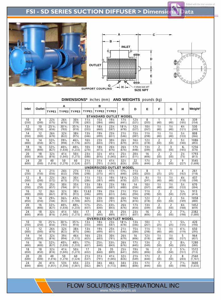
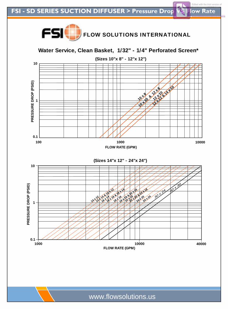
FSI - SD SERIES SUCTION DIFFUSER > Pressure Drop VS Flow Rate 6
SIZES 10" x 8" - 12" x 12"
10 x 8
10 x
10 &
12 x
8
12 x
10
12 x
12 &
14 x
10
FLOW RATE (GPM)10000100 1000
0.1
10
1
PR
ES
SU
RE
DR
OP
(PS
ID)
Water Service, Clean Basket, 1/32" - 1/4" Perforated Screen*
1000
SIZES 14" x 12" - 24" x 24"
FLOW RATE (GPM)4000010000
14 x 12
16 x 14
16 x 16 & 18 x 14
18 x 16
18 x 18 & 20 x 16
20 x 18
20 x 20 & 24 x 18
24 x 20
24 x 24
14 x 14 & 16 x 12
0.1
10
1
PR
ES
SU
RE
DR
OP
(PS
ID)
(Sizes 10"x 8" - 12"x 12")
(Sizes 14"x 12" - 24"x 24")
FLOW SOLUTIONS INTERNATIONAL
www.flowsolutions.us
30 x 30
30 x 24
Edited with the trial version of Foxit Advanced PDF Editor
To remove this notice, visit:www.foxitsoftware.com/shopping
Butterfly Valve Seating and Unseating Valve Torque Ratings Valve Sizes Full Rated Pressure Ratings (Torque for psi is expressed as in-lb, Torque for MPa is expressed as N-m) Correction
Factorsin mm 50 psi 0.4 MPa 100 psi 0.6 MPa 150 psi 1.0 MPa 200 psi 1.4 MPa 250 psi 1.6 MPa2 50 99 10 105 14 111 14 117 13 121 15 The following guidelines
may be used to estimate torque values for other
types of service.
For Dry Service:Multiply by 160%
For Lubricated Service:Multiply by 85%
For Actuator Sizing:First apply the correction
factor for the type of service then use the additional correction
factors
Multiply by 150%(Single Valve Application)
Multiply by 200%(Three way applications)
2.5 65 150 15 163 21 175 23 189 21 196 243 80 206 20 219 28 232 30 243 27 250 304 100 289 28 322 42 357 46 389 43 410 505 125 422 41 481 62 540 70 597 66 643 786 150 598 58 690 90 782 102 874 97 935 1148 200 1059 103 1182 154 1306 170 1429 159 1517 185
10 250 1670 163 1872 243 2074 269 2275 253 2403 29212 300 2568 250 2794 363 3023 392 3248 361 3401 41414 350 2639 257 3069 399 3500 454 3964 441 4267 51916 400 4260 415 4879 634 5500 714 5987 666 6280 76418 450 6287 612 7243 940 8199 1065 9183 1022 9817 119520 500 8360 814 9180 1192 10000 1298 10859 1208 11409 138924 60030 750 27313 2660 29407 3818 31500 4090 33530 3731 34844 424136 900 54667 5323 57034 7405 59399 7712 61793 6877 63351 771142 1050 82460 8030 86034 11170 89600 11633 - - - - - - - - - - - -48 1200 108015 10518 112704 14633 117376 15239 122101 13588 125177 15236
The above torques are for reference only. They were calculated from test data using clean, wet fluids (i.e. water) at ambient temperatures during on/off service. During actual service, hydrodynamic torque may meet or exceed the above listed seating and unseating torques. Therefore, hydrodynamic torque must be considered during system design to ensure proper valve and actuator selection. As always, a Titan FCI application engineer is ready to assist with valve and actuator selection.
Butterfly Valve Cv Flow Coefficient Values (GPM @ 1ΔP)Valves Sizes Angle of Valve Disc Rotation
in mm 10° 20° 30° 40° 50° 60° 70° 80° 90°2 50 0.06 3 7 15 27 44 70 105 115
2.5 65 0.10 6 12 25 45 75 119 178 1963 80 0.20 9 18 39 70 116 183 275 3024 100 0.30 17 36 78 139 230 364 546 6005 125 0.50 29 61 133 237 392 620 930 10226 150 0.80 45 95 205 366 605 958 1437 15798 200 2 89 188 408 727 1202 1903 2854 3136
10 250 3 151 320 694 1237 2049 3240 4859 534012 300 4 234 495 1072 1911 3162 5005 7507 825014 350 6 338 715 1549 2761 4568 7230 10844 1191716 400 8 464 983 2130 3797 6282 9942 14913 1638818 450 11 615 1302 2822 5028 8320 13168 19752 2170520 500 14 791 1647 3628 6465 10698 16931 25396 2790824 600 22 1222 2587 5605 9989 16528 26157 39236 4311630 750 37 2080 4406 9546 17010 28147 44545 66818 7324636 900 260 3050 6730 12740 20220 32500 52500 79600 8750040 1000 313 3665 8089 15942 2429 39056 63093 95660 10515442 1050 350 4095 9040 17108 27150 43640 70500 106890 11750048 1200 455 5365 11840 22400 30600 51200 92300 140000 154000
This chart can be used as a guide only due to the numerous variations of flow conditions that may occur during actual service.
Flow Rate Limits (On/Off Service)
Fluids 20 ft/sec 6 m/sec
Gases 175 ft/sec 54 m/sec
This table lists velocity limits for on/off services only. Additionally, for throttling service, the flow velocity should not exceed 20 ft/sec for liquids and 175 ft/sec for gases.
Seat Material Temperature Ratings
Buna-N +10 ~ 180 °F -12 ~ 82 °C
EPDM -30 ~ 225 °F -34 ~107 °C
This table lists the theoretical temperature limits for elastomers. During actual service, hardening of the elastomer may cause the torque to
Pressure Ratings (Bidirectional)
2" ~ 12" 200 psig 14 bar
14" ~ 24" 150 psig 10 bar
Butterfly Valve is mated between two flanges for bidirectional service and the disc is in the closed position.
Pressure Ratings (Dead-End)
2" ~ 12" 150 psig 10 bar
14" ~ 24" 100 psig 7 bar
Butterfly Valve is installed for dead-end service without a downstream flange. Disc is in the closed position. Please note, standard valves are not designed for dead-end service. Dead-end service must be specified by the customer.
Cv = FlowCoefficient
Q = SpecificGravityofliquidat60°FG = FlowrateinU.S.gallonsperminute(GPM)
ΔP= Pressuredropinpoundspersquareinch(PSI)
C = Q v *G P
Cv Equation For Liquids
The Flow Coefficient (designated as Cv) is a physical measurement that specifies the number of gallons per minute (GPM) that can pass through a piping component, at room temperature, and create a one (1) psi differential (ΔP) across the piping component.
Titan Flow Control > Engineering & Technical Data
> 290 Corporate Drive > Lumberton, NC 28358 > 910-735-0000 T > 910-738-3848 F
®
TITAN [email protected]
FSI - SD SERIES SUCTION DIFFUSER > Screen Opening Detail
6
www.flowsolutions.us
Butterfly Valve Seating and Unseating Valve Torque Ratings Valve Sizes Full Rated Pressure Ratings (Torque for psi is expressed as in-lb, Torque for MPa is expressed as N-m) Correction
Factorsin mm 50 psi 0.4 MPa 100 psi 0.6 MPa 150 psi 1.0 MPa 200 psi 1.4 MPa 250 psi 1.6 MPa2 50 99 10 105 14 111 14 117 13 121 15 The following guidelines
may be used to estimate torque values for other
types of service.
For Dry Service:Multiply by 160%
For Lubricated Service:Multiply by 85%
For Actuator Sizing:First apply the correction
factor for the type of service then use the additional correction
factors
Multiply by 150%(Single Valve Application)
Multiply by 200%(Three way applications)
2.5 65 150 15 163 21 175 23 189 21 196 243 80 206 20 219 28 232 30 243 27 250 304 100 289 28 322 42 357 46 389 43 410 505 125 422 41 481 62 540 70 597 66 643 786 150 598 58 690 90 782 102 874 97 935 1148 200 1059 103 1182 154 1306 170 1429 159 1517 185
10 250 1670 163 1872 243 2074 269 2275 253 2403 29212 300 2568 250 2794 363 3023 392 3248 361 3401 41414 350 2639 257 3069 399 3500 454 3964 441 4267 51916 400 4260 415 4879 634 5500 714 5987 666 6280 76418 450 6287 612 7243 940 8199 1065 9183 1022 9817 119520 500 8360 814 9180 1192 10000 1298 10859 1208 11409 138924 600 15427 1502 16813 2183 18200 2363 18728 2084 19155 233230 750 27313 2660 29407 3818 31500 4090 33530 3731 34844 424136 900 54667 5323 57034 7405 59399 7712 61793 6877 63351 771142 1050 82460 8030 86034 11170 89600 11633 - - - - - - - - - - - -48 1200 108015 10518 112704 14633 117376 15239 122101 13588 125177 15236
The above torques are for reference only. They were calculated from test data using clean, wet fluids (i.e. water) at ambient temperatures during on/off service. During actual service, hydrodynamic torque may meet or exceed the above listed seating and unseating torques. Therefore, hydrodynamic torque must be considered during system design to ensure proper valve and actuator selection. As always, a Titan FCI application engineer is ready to assist with valve and actuator selection.
Butterfly Valve Cv Flow Coefficient Values (GPM @ 1ΔP)Valves Sizes Angle of Valve Disc Rotation
in mm 10° 20° 30° 40° 50° 60° 70° 80° 90°2 50 0.06 3 7 15 27 44 70 105 115
2.5 65 0.10 6 12 25 45 75 119 178 1963 80 0.20 9 18 39 70 116 183 275 3024 100 0.30 17 36 78 139 230 364 546 6005 125 0.50 29 61 133 237 392 620 930 10226 150 0.80 45 95 205 366 605 958 1437 15798 200 2 89 188 408 727 1202 1903 2854 3136
10 250 3 151 320 694 1237 2049 3240 4859 534012 300 4 234 495 1072 1911 3162 5005 7507 825014 350 6 338 715 1549 2761 4568 7230 10844 1191716 400 8 464 983 2130 3797 6282 9942 14913 1638818 450 11 615 1302 2822 5028 8320 13168 19752 2170520 500 14 791 1647 3628 6465 10698 16931 25396 2790824 600 22 1222 2587 5605 9989 16528 26157 39236 4311630 750 37 2080 4406 9546 17010 28147 44545 66818 7324636 900 260 3050 6730 12740 20220 32500 52500 79600 8750040 1000 313 3665 8089 15942 2429 39056 63093 95660 10515442 1050 350 4095 9040 17108 27150 43640 70500 106890 11750048 1200 455 5365 11840 22400 30600 51200 92300 140000 154000
This chart can be used as a guide only due to the numerous variations of flow conditions that may occur during actual service.
Flow Rate Limits (On/Off Service)
Fluids 20 ft/sec 6 m/sec
Gases 175 ft/sec 54 m/sec
This table lists velocity limits for on/off services only. Additionally, for throttling service, the flow velocity should not exceed 20 ft/sec for liquids and 175 ft/sec for gases.
Seat Material Temperature Ratings
Buna-N +10 ~ 180 °F -12 ~ 82 °C
EPDM -30 ~ 225 °F -34 ~107 °C
This table lists the theoretical temperature limits for elastomers. During actual service, hardening of the elastomer may cause the torque to
Pressure Ratings (Bidirectional)
2" ~ 12" 200 psig 14 bar
14" ~ 24" 150 psig 10 bar
Butterfly Valve is mated between two flanges for bidirectional service and the disc is in the closed position.
Pressure Ratings (Dead-End)
2" ~ 12" 150 psig 10 bar
14" ~ 24" 100 psig 7 bar
Butterfly Valve is installed for dead-end service without a downstream flange. Disc is in the closed position. Please note, standard valves are not designed for dead-end service. Dead-end service must be specified by the customer.
Cv = FlowCoefficient
Q = SpecificGravityofliquidat60°FG = FlowrateinU.S.gallonsperminute(GPM)
ΔP= Pressuredropinpoundspersquareinch(PSI)
C = Q v *G P
Cv Equation For Liquids
The Flow Coefficient (designated as Cv) is a physical measurement that specifies the number of gallons per minute (GPM) that can pass through a piping component, at room temperature, and create a one (1) psi differential (ΔP) across the piping component.
Titan Flow Control > Engineering & Technical Data
> 290 Corporate Drive > Lumberton, NC 28358 > 910-735-0000 T > 910-738-3848 F
®
TITAN [email protected]
FSI-SUCTION DIFFUSER Installation and Maintenance Instructions 6
www.flowsolutions.us
Strainer Installation Instructions
! Ensure all machined surfaces are free of defects and that the inside of the strainer is free of foreign objects. ! For horizontal pipelines, the strainer should be installed such that the blow-down connection is pointed downwards. ! For flanged end strainers, the flange bolting should be tightened gradually in a back and forth clockwise pattern. Threaded end strainers should use an appropriate sealant. ! Once installed, increase line pressure gradually and check for leakage around joints. ! If the strainer is supplied with a start-up screen, monitor pressure drop carefully.
Strainer Removal Instructions
! Drain piping ! Vent line to relieve pressure. ! Loosen cover and open to access screen.
Remove, clean and replace screen in original position (Note: In some instances, a high pressure water jet or steam may be required for effective cleaning).
! Inspect cover gasket for damage. If necessary, replace. (Note: If spiral wound gaskets have been used, they must be replaced and cannot be used again).
! Tighten cover. The strainer is ready for line start-up
CAUTION SHOULD BE TAKEN DUE TO POSSIBLE EMISSION OF PROCESS MATERIAL FROM PIPING. ALWAYS ENSURE NO LINE PRESSURE EXISTS WHEN OPENING COVER.
Maintenance Instructions For maximum efficiency, determine the length of time it takes for the pressure drop to double that in the clean condition. Once the pressure drop reaches an unacceptable value, shut down line and follow the “Basket Removal Instructions” above. A pressure gauge installed before and after the strainer inline will indicate pressure loss due to clogging and may be used to determine when cleaning is required.
Trouble Shooting Guides and Diagnostic Techniques
! After pressurizing, inspect cover and other joints for leakage. Gasket replacement or cover tightening is necessary if leakage occurs.
! If the required filtration is not taking place, ensure the screen is installed in the correct position, that being flush to the upper and lower screen seating surfaces.
Limited Warranty All products are warranted to be free of defects in material and workmanship for a period of one year from the date of shipment, subject to the limitations below: If the purchaser believes a product defective, the purchaser shall: (a) Notify the manufacturer, state the alleged defect and request permission to return the product. (b) If permission is given, return the product with transportation prepaid. If the product is accepted for return and found to be defective, the manufacturer will, at its discretion, either repair or replace the product, f.o.b. factory, within 60 days of receipt, or refund the purchase price.
Other than to repair, replace or refund described above, the purchaser agrees that the manufacturer shall not be liable for any losses, costs, expenses or damages of any kind arising out of the product, its use, installation or replacement, labeling, instructions, information or technical data of any kind, description of product use, sample or model, warnings or lack of foregoing. No other warranties, written or oral, expressed or implied, including the warranties of fitness for a particular purpose and merchantability, are made or authorized. No affirmation of fact, promise, description of product use or sample or model shall create any warranty from the manufacturer, unless signed by the president or vice-president. These products are not manufactured, sold or intended for personal, family or household purposes.
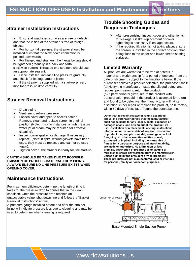
Base Mounted Single Suction Pump
FSI TRIPLE DUTY VALVE
FSI SUCTION DIFFUSER
Edited with the trial version of Foxit Advanced PDF Editor
To remove this notice, visit:www.foxitsoftware.com/shopping
SUCTION DIFFUSERS, COMBINATION AND TRIPLE DUTY VALVES
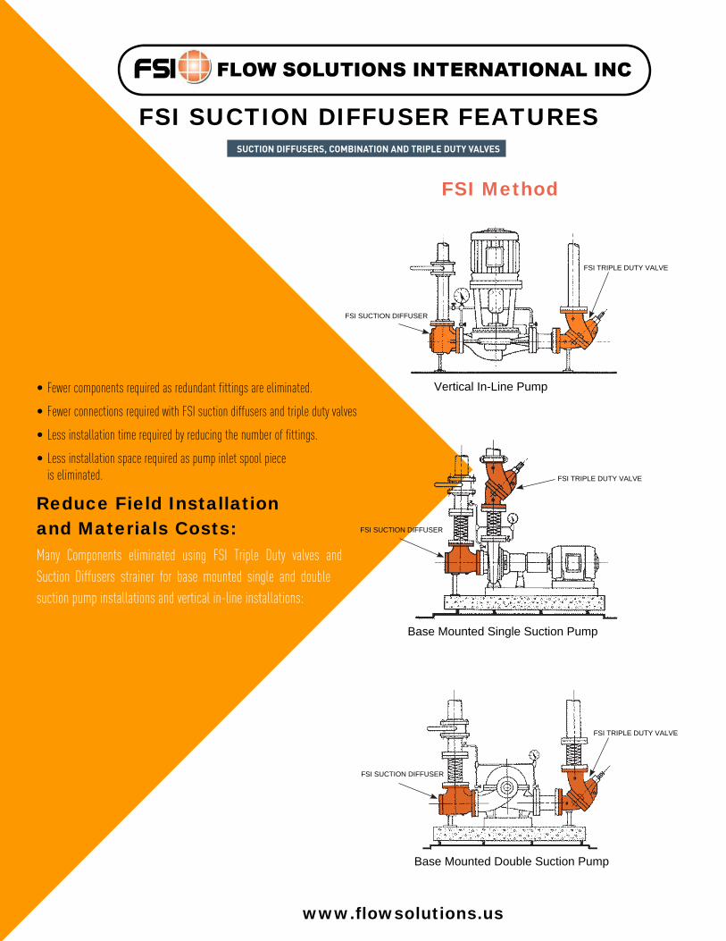
FSI SUCTION DIFFUSER FEATURES
• Fewer components required as redundant fittings are eliminated.
• Fewer connections required with FSI suction diffusers and triple duty valves
• Less installation time required by reducing the number of fittings.
• Less installation space required as pump inlet spool piece is eliminated.
Reduce Field Installation
and Materials Costs:
Many Components eliminated using FSI Triple Duty valves and Suction Diffusers strainer for base mounted single and double suction pump installations and vertical in-line installations:
Vertical In-Line Pump
FSI Method
Base Mounted Single Suction Pump
Base Mounted Double Suction Pump
FSI TRIPLE DUTY VALVE
FSI SUCTION DIFFUSER
FSI SUCTION DIFFUSER
FSI TRIPLE DUTY VALVE
FSI TRIPLE DUTY VALVE
FSI SUCTION DIFFUSER
www.flowsolutions.us
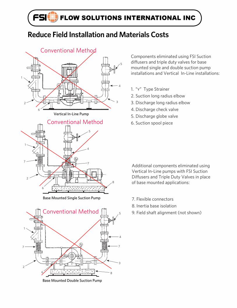
Components eliminated using FSI Suctiondiffusers and triple duty valves for basemounted single and double suction pump installations and Vertical In-Line installations:
1. “y” Type Strainer2 . Suction long radius elbow3. Discharge long radius elbow4 . Discharge check valve5 . Discharge globe valve6 . Suction spool piece
Additional components eliminated using Vertical In-Line pumps with FSI Suction Diffusers and Triple Duty Valves in placeof base mounted applications:
1
2 3
4
5
6Vertical In-Line Pump
Conventional Method
3
4
Base Mounted Double Suction Pump
7
5
1
7
2
6 8
1
2
7
Base Mounted Single Suction Pump
8
6
4
5
7
7. Flexible connectors8 . Inertia base isolation9. Field shaft alignment (not shown)
Reduce Field Installation and Materials Costs
Conventional Method
Conventional Method
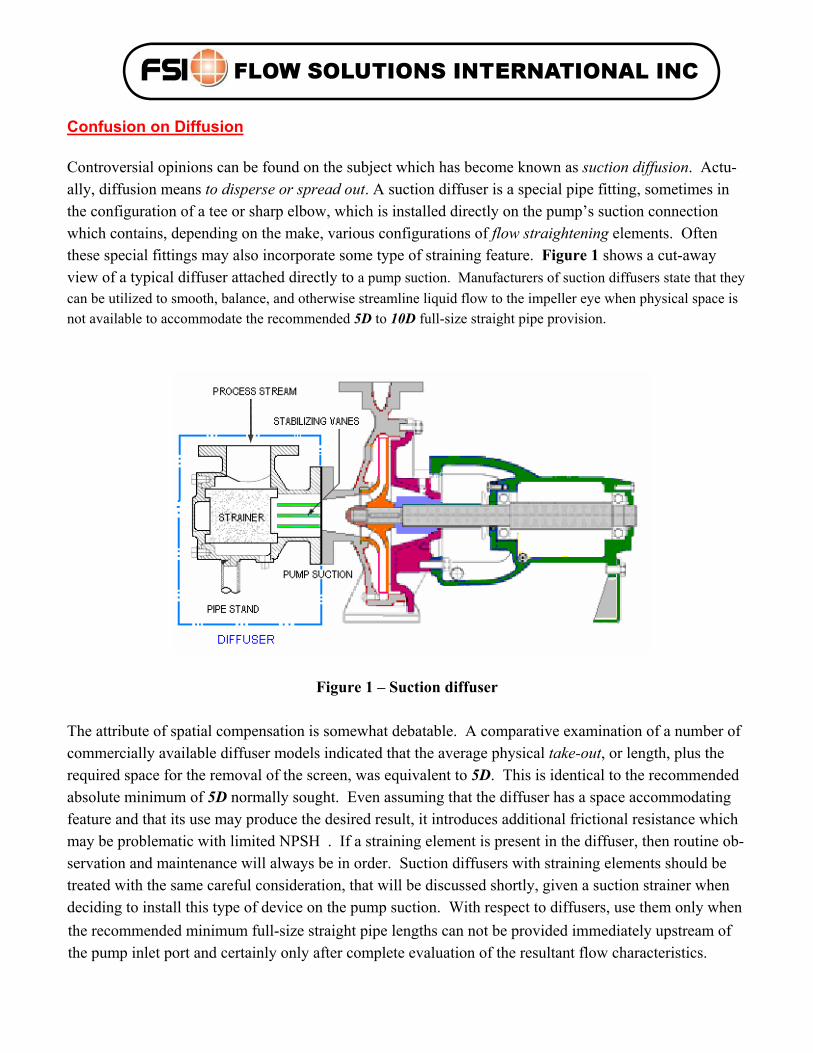
Confusion on Diffusion Controversial opinions can be found on the subject which has become known as suction diffusion. Actu-ally, diffusion means to disperse or spread out. A suction diffuser is a special pipe fitting, sometimes in the configuration of a tee or sharp elbow, which is installed directly on the pump’s suction connection which contains, depending on the make, various configurations of flow straightening elements. Often these special fittings may also incorporate some type of straining feature. Figure 1 shows a cut-away view of a typical diffuser attached directly to a pump suction. Manufacturers of suction diffusers state that they can be utilized to smooth, balance, and otherwise streamline liquid flow to the impeller eye when physical space is not available to accommodate the recommended 5D to 10D full-size straight pipe provision.
Figure 1 – Suction diffuser
The attribute of spatial compensation is somewhat debatable. A comparative examination of a number of commercially available diffuser models indicated that the average physical take-out, or length, plus the required space for the removal of the screen, was equivalent to 5D. This is identical to the recommended absolute minimum of 5D normally sought. Even assuming that the diffuser has a space accommodating feature and that its use may produce the desired result, it introduces additional frictional resistance which may be problematic with limited NPSH . If a straining element is present in the diffuser, then routine ob-servation and maintenance will always be in order. Suction diffusers with straining elements should be treated with the same careful consideration, that will be discussed shortly, given a suction strainer when deciding to install this type of device on the pump suction. With respect to diffusers, use them only when the recommended minimum full-size straight pipe lengths can not be provided immediately upstream of the pump inlet port and certainly only after complete evaluation of the resultant flow characteristics.