Embed Size (px)
Citation preview

Ediso
n™
Circuit Protection
Product CatalogCircuit Protection Products
PR
OD
UC
T C
ATA
LO
G

Index by Domestic Catalog Numbers Listed Numeric-AlphaCatalog Number Page12ABCNA(Amp) . . . . . . . . . . 11512CAV . . . . . . . . . . . . . . . . . . 11512SDLSJ(amp) . . . . . . . . . . . 11812SFLSJ(Amp) . . . . . . . . . . . 11812SKLSJ(Amp) . . . . . . . . . . . 11815.5ABFNA(Amp) . . . . . . . . . 11515.5CAV, CAVH. . . . . . . . . . . 11517.5ABGNA(Amp) . . . . . . . . . 11517.5CAV . . . . . . . . . . . . . . . . 11517.5SDLSJ(Amp) . . . . . . . . . 11817.5SDMSJ(Amp) . . . . . . . . . 11817.5SFLSJ(amp) . . . . . . . . . . 11817.5SFMSJ(Amp) . . . . . . . . . 11824ABGNA(Amp) . . . . . . . . . . 11524CAV . . . . . . . . . . . . . . . . . . 11524SFMSJ(Amp). . . . . . . . . . . 11825SFMSJ(Amp). . . . . . . . . . . 1182.75VFRHA(Amp)R. . . . . . . . 1012.75VKRHA(Amp)R . . . . . . . 1012.75VKRHK(Amp)R . . . . . . . 10127.6SDMSJ(Amp) . . . . . . . . . 11827.6SFMSJ(Amp) . . . . . . . . . 1182703 . . . . . . . . . . . . . . . . . . . 1213.6ABWNA(Amp) . . . . . . . . . 1153.6ABCNA(Amp) . . . . . . . . . . 1153.6ABGNA(Amp) . . . . . . . . . . 1153.6ADLSJ(Amp) . . . . . . . . . . 1183.6ADOSJ(Amp) . . . . . . . . . . 1183.6CAV . . . . . . . . . . . . . . . . . 1153.6WDLSJ(Amp) . . . . . . . . . . 1183.6WDOSJ(Amp). . . . . . . . . . 1183.6WFLSJ(Amp) . . . . . . . . . . 1183.6WFOSJ(Amp) . . . . . . . . . . 1183.6WKLSJ(Amp) . . . . . . . . . . 11836CAV . . . . . . . . . . . . . . . . . . 11536SDQSJ(Amp). . . . . . . . . . . 11836SFQSJ(Amp) . . . . . . . . . . . 1183835 Series. . . . . . . . . . . . . . 15038CAV, CAVH . . . . . . . . . . . . 1154164 . . . . . . . . . . . . . . . . . . . . 555.5ABWNA(Amp) . . . . . . . . . 1155.5AMWNA(Amp) . . . . . . . . . 1155.5CAV, CAVH. . . . . . . . . . . . 1155.5VFNHA(Amp)R. . . . . . . . . 1015.5VKNHA(Amp)R . . . . . . . . . 1015.5VKNHK(Amp)R . . . . . . . . 1017.2ABWNA(Amp) . . . . . . . . . 1157.2ABCNA(Amp) . . . . . . . . . . 1157.2CAV . . . . . . . . . . . . . . . . . 1157.2SDLSJ(Amp) . . . . . . . . . . 1187.2SFLSJ(Amp). . . . . . . . . . . 1187.2WKMSJ(Amp). . . . . . . . . . 1188.25FFNHA(Amp)E . . . . . . . . 1088.25FFNHK(Amp)E . . . . . . . . 1088.25BFNHA(Amp)E. . . . . . . . 1088.25BFNHK(Amp)E. . . . . . . . 108
Catalog Number Page8.25BKNHK(Amp)E 1088000 Series Fuseblocks . . . . 150A3354705 . . . . . . . . . . . . . . . 115A3354745 . . . . . . . . . . . . . . . 121ABC. . . . . . . . . . . . . . . . . . . . . 43ACK. . . . . . . . . . . . . . . . . . . . . 54ACL . . . . . . . . . . . . . . . . . . . . . 54AGC . . . . . . . . . . . . . . . . . . . . 43ALS . . . . . . . . . . . . . . . . . . . . . 54ANL . . . . . . . . . . . . . . . . . . . . . 55ANN. . . . . . . . . . . . . . . . . . . . . 56ATC . . . . . . . . . . . . . . . . . . . . . 46ATM. . . . . . . . . . . . . . . . . . . . . 46BH Modular Blocks . . . . . . . . . . 135Box Cover Units . . . . . . . . . . 136CC Fuseblocks . . . . . . . . . . . 133CCLB. . . . . . . . . . . . . . . . . . . . 52CCLW . . . . . . . . . . . . . . . . . . . 52CDNC . . . . . . . . . . . . . . . . . . . 92CDSC . . . . . . . . . . . . . . . . . . . 92Clip Clamps. . . . . . . . . . . . . . 153CM(XX)CF. . . . . . . . . . . . . . . . 95C(XX)BS . . . . . . . . . . . . . . . . . 98C(XX)F . . . . . . . . . . . . . . . . . . 98C(XX)FBS . . . . . . . . . . . . . . . . 98D16, D27, D33, D125 . . . . . . . . 89DRA-1, DRA-2 . . . . . . . . . . . 134E100S . . . . . . . . . . . . . . . . . . . 79E100SF . . . . . . . . . . . . . . . . . . 79E13S . . . . . . . . . . . . . . . . . . . . 60E15SF . . . . . . . . . . . . . . . . . . . 61E25SFX. . . . . . . . . . . . . . . . . . 64E50S . . . . . . . . . . . . . . . . . . . . 68E50SF . . . . . . . . . . . . . . . . . . . 68E60C . . . . . . . . . . . . . . . . . . . . .71E60SF . . . . . . . . . . . . . . . . . . . 73E70SF . . . . . . . . . . . . . . . . . . . 75EBS. . . . . . . . . . . . . . . . . . . . . 31ECNR . . . . . . . . . . . . . . . . . . . . 1ECSR . . . . . . . . . . . . . . . . . . . . 1EDCC . . . . . . . . . . . . . . . . . . . 27EPDB Series . . . . . . . . . . . . . 138ERFL . . . . . . . . . . . . . . . . . . . . 45ERFS. . . . . . . . . . . . . . . . . . . . 45ET . . . . . . . . . . . . . . . . . . . . . . 83FE . . . . . . . . . . . . . . . . . . . . . . 83FEE . . . . . . . . . . . . . . . . . . . . . 83FM. . . . . . . . . . . . . . . . . . . . . . 83FMM . . . . . . . . . . . . . . . . . . . . 83FP Series (Fusepullers) . . . . 153G Fuseblocks . . . . . . . . . . . . 132GBB. . . . . . . . . . . . . . . . . . . . . 43GDA . . . . . . . . . . . . . . . . . . . . 41GDB . . . . . . . . . . . . . . . . . . . . 41GDC . . . . . . . . . . . . . . . . . . . . 41GMA . . . . . . . . . . . . . . . . . . . . 42
Catalog Number PageGMC . . . . . . . . . . . . . . . . . . . 42GMD . . . . . . . . . . . . . . . . . . . . 42H Fuseblocks . . . . . . . . . . . . 123HCLR . . . . . . . . . . . . . . . . . . . 29HCTR . . . . . . . . . . . . . . . . . . . 29HEB. . . . . . . . . . . . . . . . . . . . 146HET . . . . . . . . . . . . . . . . . . . . 146HEX. . . . . . . . . . . . . . . . . . . . 146HEY. . . . . . . . . . . . . . . . . . . . 146HKP Series . . . . . . . . . . . . . . 149HPF . . . . . . . . . . . . . . . . . . . . 149HVAC Disconnects . . . . . . . . 151In-Line Fuseholders . . . . . . . 148J Fuseblocks . . . . . . . . . . . . . 129JDL . . . . . . . . . . . . . . . . . . . . . 18JFL . . . . . . . . . . . . . . . . . . . . . 20JHL . . . . . . . . . . . . . . . . . . . . . 59KON . . . . . . . . . . . . . . . . . 35, 92KOS . . . . . . . . . . . . . . . . . . 35, 92LCL . . . . . . . . . . . . . . . . . . . . . .14LCT . . . . . . . . . . . . . . . . . . . . . 84LCU. . . . . . . . . . . . . . . . . . . . . 14LENRK . . . . . . . . . . . . . . . . . . . 6LESRK . . . . . . . . . . . . . . . . . . . 6LET . . . . . . . . . . . . . . . . . . . . . 84LMMT . . . . . . . . . . . . . . . . . . . 84LMT. . . . . . . . . . . . . . . . . . . . . 84MAI . . . . . . . . . . . . . . . . . . . . . 88MAX . . . . . . . . . . . . . . . . . . . . 46M Fuseblocks . . . . . . . . . . . . 134MCL. . . . . . . . . . . . . . . . . . . . . 31MDA . . . . . . . . . . . . . . . . . . . . 44MDL. . . . . . . . . . . . . . . . . . . . . 44MEN . . . . . . . . . . . . . . . . . . . . 33MEQ . . . . . . . . . . . . . . . . . . . . 33MID . . . . . . . . . . . . . . . . . . . . . 33MKE . . . . . . . . . . . . . . . . . . . . 45MOL . . . . . . . . . . . . . . . . . . . . 31MV055 Series . . . . . . . . . . . . 104MV155 Series . . . . . . . . . . . . 111NCLR. . . . . . . . . . . . . . . . . . . . 11NH. . . . . . . . . . . . . . . . . . . . . . 90No. 213 . . . . . . . . . . . . . . . . . 152No. 213-R . . . . . . . . . . . . . . . 152No. 216 . . . . . . . . . . . . . . . . . 152No. 216-R . . . . . . . . . . . . . . . 152No. 226 . . . . . . . . . . . . . . . . . 152No. 226-R . . . . . . . . . . . . . . . 152No. 242-R . . . . . . . . . . . . . . . 152No. 2621 . . . . . . . . . . . . . . . . 152No. 2621-R . . . . . . . . . . . . . . 152No. 263 . . . . . . . . . . . . . . . . . 152No. 263-R . . . . . . . . . . . . . . . 152No. 2641 . . . . . . . . . . . . . . . . 152No. 2641-R . . . . . . . . . . . . . . 152No. 2642 . . . . . . . . . . . . . . . . 152
Catalog Number PageNo. 2661 . . . . . . . . . . . . . . . . 152No. 2661-R . . . . . . . . . . . . . . 152No. 2662 . . . . . . . . . . . . . . . . 152No. 2662-R . . . . . . . . . . . . . . 152No. 2664 . . . . . . . . . . . . . . . . 152No. 2664-R . . . . . . . . . . . . . . 152No. 616 . . . . . . . . . . . . . . . . . 152No. 626 . . . . . . . . . . . . . . . . . 152No. 626-R . . . . . . . . . . . . . . . 152No. 642-R . . . . . . . . . . . . . . . 152No. 663 . . . . . . . . . . . . . . . . . 152No. 663-R . . . . . . . . . . . . . . . 152NZ01, NZ02 . . . . . . . . . . . . . . 89P . . . . . . . . . . . . . . . . . . . . . . . 40PB1 & PB3 Series. . . . . . . . . 141PB4, PB5 & PB7 Series . . . . 143PONC . . . . . . . . . . . . . . . . . . . 92R Fuseblocks . . . . . . . . . . . . . .123S . . . . . . . . . . . . . . . . . . . . . . . .37SA . . . . . . . . . . . . . . . . . . . . . . 38SAFELOC HRC . . . . . . . . . . . 98SAMI Series . . . . . . . . . . . . . 145SCLR. . . . . . . . . . . . . . . . . . . . 11SEC. . . . . . . . . . . . . . . . . . . . . 25SFC-Fuse-CAB . . . . . . . . . . . 153SFE . . . . . . . . . . . . . . . . . . . . . 46SL . . . . . . . . . . . . . . . . . . . . . . 37T . . . . . . . . . . . . . . . . . . . . . . . 39TC . . . . . . . . . . . . . . . . . . . . . . 40T Fuseblocks. . . . . . . . . . . . . 130TI500 . . . . . . . . . . . . . . . . . . . . 88TI700 . . . . . . . . . . . . . . . . . . . . 88TJN . . . . . . . . . . . . . . . . . . . . . 22TJS . . . . . . . . . . . . . . . . . . . . . 22TL . . . . . . . . . . . . . . . . . . . . . . 39UCL 25XX to 75XX . . . . . . . . . 47UCLA. . . . . . . . . . . . . . . . . . . . 47W. . . . . . . . . . . . . . . . . . . . . . . 38
Edison circuit protection solutions comply with major industrial standards and agency requirements such as: BS, IEC, DIN, UL, NEMA, SAE, CSA, CE, C-UL, etc. andare manufactured at facilities that are ISO 9000 certified. This catalog is intended to present product data and provide technical information that will help the end userwith designapplication. We reserve the right, without notice, to change design or construction of any products and to discontinue or limit distribution of any products. We also reserve the right to change or update, without notice, any technical information contained in this catalog. Once a product has been selected, itshould be tested by the user in all possible applications. Further, We take no responsibility for errors or omissions contained in this catalog, or for misapplication of anyEdison product. Extensive product information is available in the Edison product data sheets available online at www.edisonfuse.com.©2011
Index
i
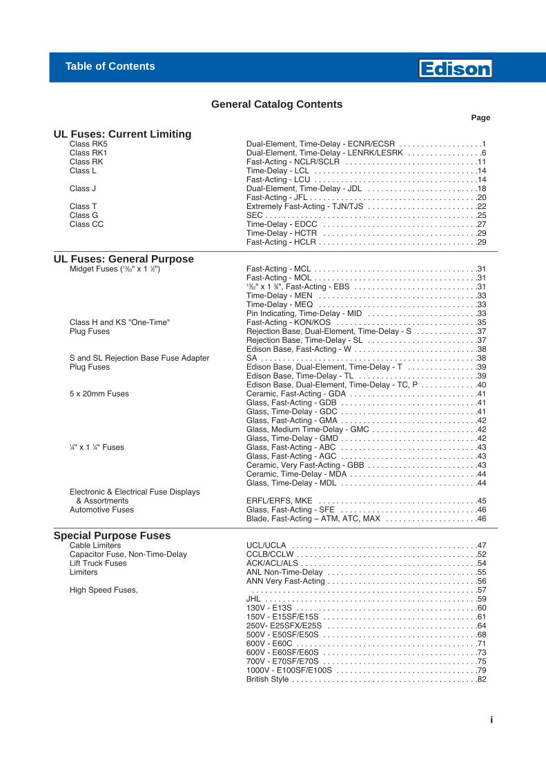
UL Fuses: Current LimitingClass RK5 Dual-Element, Time-Delay - ECNR/ECSR . . . . . . . . . . . . . . . . . . .1Class RK1 Dual-Element, Time-Delay - LENRK/LESRK . . . . . . . . . . . . . . . . .6Class RK Fast-Acting - NCLR/SCLR . . . . . . . . . . . . . . . . . . . . . . . . . . . . . .11Class L Time-Delay - LCL . . . . . . . . . . . . . . . . . . . . . . . . . . . . . . . . . . . . .14
Fast-Acting - LCU . . . . . . . . . . . . . . . . . . . . . . . . . . . . . . . . . . . . .14Class J Dual-Element, Time-Delay - JDL . . . . . . . . . . . . . . . . . . . . . . . . .18
Fast-Acting - JFL . . . . . . . . . . . . . . . . . . . . . . . . . . . . . . . . . . . . . .20Class T Extremely Fast-Acting - TJN/TJS . . . . . . . . . . . . . . . . . . . . . . . . .22Class G SEC . . . . . . . . . . . . . . . . . . . . . . . . . . . . . . . . . . . . . . . . . . . . . . . .25Class CC Time-Delay - EDCC . . . . . . . . . . . . . . . . . . . . . . . . . . . . . . . . . . .27
Time-Delay - HCTR . . . . . . . . . . . . . . . . . . . . . . . . . . . . . . . . . . .29Fast-Acting - HCLR . . . . . . . . . . . . . . . . . . . . . . . . . . . . . . . . . . . .29
UL Fuses: General PurposeMidget Fuses (13⁄32" x 1 1⁄2") Fast-Acting - MCL . . . . . . . . . . . . . . . . . . . . . . . . . . . . . . . . . . . . .31
Fast-Acting - MOL . . . . . . . . . . . . . . . . . . . . . . . . . . . . . . . . . . . . .3113⁄32" x 1 3⁄8", Fast-Acting - EBS . . . . . . . . . . . . . . . . . . . . . . . . . . . .31Time-Delay - MEN . . . . . . . . . . . . . . . . . . . . . . . . . . . . . . . . . . . .33Time-Delay - MEQ . . . . . . . . . . . . . . . . . . . . . . . . . . . . . . . . . . . .33Pin Indicating, Time-Delay - MID . . . . . . . . . . . . . . . . . . . . . . . . .33
Class H and KS "One-Time" Fast-Acting - KON/KOS . . . . . . . . . . . . . . . . . . . . . . . . . . . . . . . .35Plug Fuses Rejection Base, Dual-Element, Time-Delay - S . . . . . . . . . . . . . .37
Rejection Base, Time-Delay - SL . . . . . . . . . . . . . . . . . . . . . . . . .37Edison Base, Fast-Acting - W . . . . . . . . . . . . . . . . . . . . . . . . . . . .38
S and SL Rejection Base Fuse Adapter SA . . . . . . . . . . . . . . . . . . . . . . . . . . . . . . . . . . . . . . . . . . . . . . . . .38Plug Fuses Edison Base, Dual-Element, Time-Delay - T . . . . . . . . . . . . . . . .39
Edison Base, Time-Delay - TL . . . . . . . . . . . . . . . . . . . . . . . . . . .39Edison Base, Dual-Element, Time-Delay - TC, P . . . . . . . . . . . . .40
5 x 20mm Fuses Ceramic, Fast-Acting - GDA . . . . . . . . . . . . . . . . . . . . . . . . . . . . .41Glass, Fast-Acting - GDB . . . . . . . . . . . . . . . . . . . . . . . . . . . . . . .41Glass, Time-Delay - GDC . . . . . . . . . . . . . . . . . . . . . . . . . . . . . . .41Glass, Fast-Acting - GMA . . . . . . . . . . . . . . . . . . . . . . . . . . . . . . .42Glass, Medium Time-Delay - GMC . . . . . . . . . . . . . . . . . . . . . . . .42Glass, Time-Delay - GMD . . . . . . . . . . . . . . . . . . . . . . . . . . . . . . .42
1⁄4" x 1 1⁄4" Fuses Glass, Fast-Acting - ABC . . . . . . . . . . . . . . . . . . . . . . . . . . . . . . .43Glass, Fast-Acting - AGC . . . . . . . . . . . . . . . . . . . . . . . . . . . . . . .43Ceramic, Very Fast-Acting - GBB . . . . . . . . . . . . . . . . . . . . . . . . .43Ceramic, Time-Delay - MDA . . . . . . . . . . . . . . . . . . . . . . . . . . . . .44Glass, Time-Delay - MDL . . . . . . . . . . . . . . . . . . . . . . . . . . . . . . .44
Electronic & Electrical Fuse Displays& Assortments ERFL/ERFS, MKE . . . . . . . . . . . . . . . . . . . . . . . . . . . . . . . . . . . .45
Automotive Fuses Glass, Fast-Acting - SFE . . . . . . . . . . . . . . . . . . . . . . . . . . . . . . .46Blade, Fast-Acting – ATM, ATC, MAX . . . . . . . . . . . . . . . . . . . . .46
Special Purpose FusesCable Limiters UCL/UCLA . . . . . . . . . . . . . . . . . . . . . . . . . . . . . . . . . . . . . . . . . .47Capacitor Fuse, Non-Time-Delay CCLB/CCLW . . . . . . . . . . . . . . . . . . . . . . . . . . . . . . . . . . . . . . . . .52Lift Truck Fuses ACK/ACL/ALS . . . . . . . . . . . . . . . . . . . . . . . . . . . . . . . . . . . . . . . .54Limiters ANL Non-Time-Delay . . . . . . . . . . . . . . . . . . . . . . . . . . . . . . . . . .55
ANN Very Fast-Acting . . . . . . . . . . . . . . . . . . . . . . . . . . . . . . . . . .56High Speed Fuses, . . . . . . . . . . . . . . . . . . . . . . . . . . . . . . . . . . . . . . . . . . . . . . . . . . .57
JHL . . . . . . . . . . . . . . . . . . . . . . . . . . . . . . . . . . . . . . . . . . . . . . . .59130V - E13S . . . . . . . . . . . . . . . . . . . . . . . . . . . . . . . . . . . . . . . . .60150V - E15SF/E15S . . . . . . . . . . . . . . . . . . . . . . . . . . . . . . . . . . .61250V- E25SFX/E25S . . . . . . . . . . . . . . . . . . . . . . . . . . . . . . . . . .64500V - E50SF/E50S . . . . . . . . . . . . . . . . . . . . . . . . . . . . . . . . . . .68600V - E60C . . . . . . . . . . . . . . . . . . . . . . . . . . . . . . . . . . . . . . . . .71600V - E60SF/E60S . . . . . . . . . . . . . . . . . . . . . . . . . . . . . . . . . . .73700V - E70SF/E70S . . . . . . . . . . . . . . . . . . . . . . . . . . . . . . . . . . .751000V - E100SF/E100S . . . . . . . . . . . . . . . . . . . . . . . . . . . . . . . .79British Style . . . . . . . . . . . . . . . . . . . . . . . . . . . . . . . . . . . . . . . . . .82
General Catalog ContentsPage
Table of Contents

Special Purpose Fuses (Con’t)Trip Indicators . . . . . . . . . . . . . . . . . . . . . . . . . . . . . . . . . . . . . . . . . . . . . . . . . . .88Microswitch Adapter - MAI . . . . . . . . . . . . . . . . . . . . . . . . . . . . . . . . . . . . . . . . . . . . . . . . . . .88Type “D” Bottle Fuses . . . . . . . . . . . . . . . . . . . . . . . . . . . . . . . . . . . . . . . . . . . . . . . . . . .89Neozed Fuses . . . . . . . . . . . . . . . . . . . . . . . . . . . . . . . . . . . . . . . . . . . . . . . . . . .89NH Fuses . . . . . . . . . . . . . . . . . . . . . . . . . . . . . . . . . . . . . . . . . . . . . . . . . . .90Canadian Fuses & AccessoriesStandard Code Fuses 250V & 600V KOS/KON/PONC . . . . . . . . . . . . . . . . . . . . . . . . . . . . . . . . . . . . .92
CDSC/CDNC . . . . . . . . . . . . . . . . . . . . . . . . . . . . . . . . . . . . . . . .92Fuse Holders CAMaster HRC Fuse Holder . . . . . . . . . . . . . . . . . . . . . . . . . . . . .95
SAFEloc HRCI-CB Fuse Holder . . . . . . . . . . . . . . . . . . . . . . . . . .98
Medium Voltage FusesR-Rated Fuses 2.75 to 5.5kV . . . . . . . . . . . . . . . . . . . . . . . . . . . . . . . . . . . . . . . .101E-Rated Fuses 5.5kV MV055 . . . . . . . . . . . . . . . . . . . . . . . . . . . . . . . . . . . . . . .104
8.25kV . . . . . . . . . . . . . . . . . . . . . . . . . . . . . . . . . . . . . . . . . . . . .10815.5kV MV155 . . . . . . . . . . . . . . . . . . . . . . . . . . . . . . . . . . . . . .111
Potential Transformer Fuses 3.6 to 38kV AB, AM and CAV Series . . . . . . . . . . . . . . . . . . . . .115High Voltage DIN Distribution Fuses 3.6 to 36kV . . . . . . . . . . . . . . . . . . . . . . . . . . . . . . . . . . . . . . . . .117
Fuse Blocks, Holders & Misc.Class H (K) and R Fuse Blocks H250, H600, R250 and R600 Series . . . . . . . . . . . . . . . . . . . . .123Class J Fuse Blocks J600 Series . . . . . . . . . . . . . . . . . . . . . . . . . . . . . . . . . . . . . . . . .129Class T Fuse Blocks T300 and T600 Series . . . . . . . . . . . . . . . . . . . . . . . . . . . . . . . .130Class G Fuse Blocks BG Series . . . . . . . . . . . . . . . . . . . . . . . . . . . . . . . . . . . . . . . . . .132Class CC Fuse Blocks BC Series . . . . . . . . . . . . . . . . . . . . . . . . . . . . . . . . . . . . . . . . . .133Midget Fuse Blocks BM Series . . . . . . . . . . . . . . . . . . . . . . . . . . . . . . . . . . . . . . . . . .134DIN and American Rail Adapters DRA-1 and DRA-2 . . . . . . . . . . . . . . . . . . . . . . . . . . . . . . . . . . .134Modular Fuse blocks BH Series . . . . . . . . . . . . . . . . . . . . . . . . . . . . . . . . . . . . . . . . . .135Edison Base Plug Fuse Holders Box Cover Units . . . . . . . . . . . . . . . . . . . . . . . . . . . . . . . . . . . . .136Power Blocks Enclosed Power Distribution Blocks . . . . . . . . . . . . . . . . . . . . . .138
High SCCR Terminal Blocks . . . . . . . . . . . . . . . . . . . . . . . . . . . .141Power Distrbution Blocks . . . . . . . . . . . . . . . . . . . . . . . . . . . . . .143
SAMI Fuse Covers For Class J, RK, K5, H and Midget Fuses . . . . . . . . . . . . . . . . .145In-line Fuse Holders Class CC and Midget Fuses - HEB/HET/HEY/HEX . . . . . . . . . .146Panel Mount Fuse Holders 1⁄4" x 1 1⁄4" Fuses - HKP, HKP-HH/HKP-W . . . . . . . . . . . . . . . . . .149
13⁄32" x 1 1⁄2" Fuses - HPF . . . . . . . . . . . . . . . . . . . . . . . . . . . . . . . .149Fuse Blocks 13⁄32" x 1 1⁄2" Fuses - 3835 Series . . . . . . . . . . . . . . . . . . . . . . . . . .150
1⁄4" x 1 1⁄4" Fuses - S-8000 Series . . . . . . . . . . . . . . . . . . . . . . . . .150HVAC Disconnects B22 Series . . . . . . . . . . . . . . . . . . . . . . . . . . . . . . . . . . . . . . . . .151Fuse Reducers Class H, J, K, & R . . . . . . . . . . . . . . . . . . . . . . . . . . . . . . . . . . . .152Spare Fuse Cabinet SFC-FUSE-CAB . . . . . . . . . . . . . . . . . . . . . . . . . . . . . . . . . . . . .153Fuse Clip Clamp . . . . . . . . . . . . . . . . . . . . . . . . . . . . . . . . . . . . . . . . . . . . . . . . . .153Fuse Pullers FP Series . . . . . . . . . . . . . . . . . . . . . . . . . . . . . . . . . . . . . . . . . .153
Elements of a Practical Fuse Specification 154Fuse Terminology 155Cross Reference Guide 156
General Catalog Contents (Con’t.)Page
ii
Circuit Protection
Circuit Protection
1For additional information, visit www.edisonfuse.com
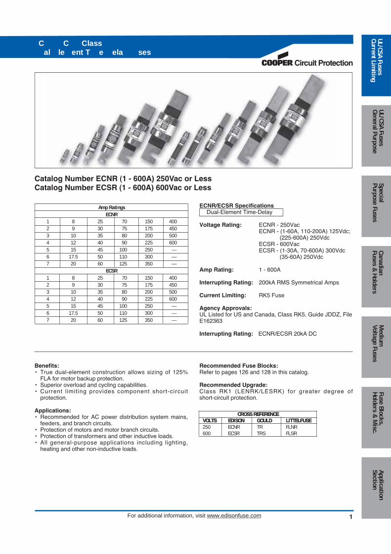
Amp RatingsECNR
1 8 25 70 150 4002 9 30 75 175 4503 10 35 80 200 5004 12 40 90 225 6005 15 45 100 250 —6 17.5 50 110 300 —7 20 60 125 350 —
ECSR1 8 25 70 150 4002 9 30 75 175 4503 10 35 80 200 5004 12 40 90 225 6005 15 45 100 250 —6 17.5 50 110 300 —7 20 60 125 350 —
ECNR/ECSR SpecificationsDual-Element Time-Delay
Voltage Rating: ECNR - 250Vac ECNR - (1-60A, 110-200A) 125Vdc;
(225-600A) 250VdcECSR - 600VacECSR - (1-30A, 70-600A) 300Vdc
(35-60A) 250Vdc
Amp Rating: 1 - 600A
Interrupting Rating: 200kA RMS Symmetrical Amps
Current Limiting: RK5 Fuse
Agency Approvals:UL Listed for US and Canada, Class RK5, Guide JDDZ, FileE162363
Interrupting Rating: ECNR/ECSR 20kA DC
Recommended Fuse Blocks:Refer to pages 126 and 128 in this catalog.
Recommended Upgrade:Class RK1 (LENRK/LESRK) for greater degree of short-circuit protection.
Catalog Number ECNR (1 - 600A) 250Vac or LessCatalog Number ECSR (1 - 600A) 600Vac or Less
Benefits:• True dual-element construction allows sizing of 125%
FLA for motor backup protection.• Superior overload and cycling capabilities.• Current l imit ing provides component short-circuit
protection.
Applications:• Recommended for AC power distribution system mains,
feeders, and branch circuits.• Protection of motors and motor branch circuits.• Protection of transformers and other inductive loads.• All general-purpose applications including lighting,
heating and other non-inductive loads.
C C Class al le ent T e ela ses
Medium
Voltage FusesUL/CSA FusesCurrent Lim
itingUL/CSA FusesGeneral Purpose
SpecialPurpose Fuses
CanadianFuses &
HoldersApplicationSection
Fuse Blocks,Holders &
Misc.
CROSS REFERENCEVOLTS EDISON GOULD LITTELFUSE250 ECNR TR FLNR600 ECSR TRS FLSR

characteristics of these fuses typically allows them to besized closer to the running ampacity of inductive loads toreduce cost and provide improved overcurrent protection. These fuses will override normal equipment current surges to reduce unnecessary fuse openings. Theyare the most popular fuses used in the industry and themost economical for most applications, especially motorsand transformers. They have moderate current limitation.
2
C C Class al le ent T e ela ses
For additional information, visit www.edisonfuse.com
ECNR/ECSR Dual Element FusesThese fuses are recommended for AC power distributionsystem mains, feeders and branch circuits having inductiveloads (motors, transformers) or non-inductive loads (lighting, heating) where the available short-circuit currentdoes not exceed 200,000 RMS symmetrical amps. These“dual-element, time-delay” fuses have minimum industrystandard time-delay of 10 seconds at 5 times the fuse rating(8 sec. minimum for 250V, 30A and less). The time-delay
Overall MaxCatalog Length - in Diameter - inNumber Amps A B
0-30 2 0.5635-60 3 0.81
70-100 5.88 1.06ECNR 110-200 7.13 1.56
225-400 8.63 2.38450-600 10.38 2.88
0-30 5 0.8135-60 5.5 1.06
ECSR65-100 7.88 1.11110-200 9.63 1.61225-400 11.63 2.34450-600 13.38 2.88
Class R fuses will fit Class H, K and R fuse clips. Class R fuse clips will only accept Class R fuses. Fuses rated 600Vacor less may be applied at any lower voltage. Contact Edison Custom Satisfaction for special products or applications.
Dimensions
Ferrule Design–0 through 60 Amps Knife Blade–70 through 600 Amps
Med
ium
Volta
ge F
uses
UL/C
SA F
uses
Curr
ent L
imiti
ngUL
/CSA
Fus
esGe
nera
l Pur
pose
Spec
ial
Purp
ose
Fuse
sCa
nadi
anFu
ses
& H
olde
rsAp
plic
atio
nSe
ctio
nFu
se B
lock
s,Ho
lder
s &
Mis
c.

8 10 15 30 60 100
200
400
600
Average Melt Time-Current CurvesCat No. ECNR (Amp)
Circuit Protection
3
C C Class al le ent T e ela ses
For additional information, visit www.edisonfuse.com
Medium
Voltage FusesUL/CSA FusesCurrent Lim
itingUL/CSA FusesGeneral Purpose
SpecialPurpose Fuses
CanadianFuses &
HoldersApplicationSection
Fuse Blocks,Holders &
Misc.

4
C C Class al le ent T e ela ses
For additional information, visit www.edisonfuse.com
AMPRATING
RMS SYMMETRICAL CURRENTS IN AMPS1,
000
10010
10,0
00
600A
10
100
TIM
E IN
SEC
ONDS
1
.1
.01
20,0
00
400A
200A
100A
60A
30A
15A
10AAMP
RATING
RMS SYMMETRICAL CURRENTS IN AMPS
10.1
100
10
100
TIM
E IN
SEC
ONDS
1
.1
.01
700
1A 2A 4A 5A 8A
Average Melt Time-Current CurvesCat No. ECSR (Amp)
Med
ium
Volta
ge F
uses
UL/C
SA F
uses
Curr
ent L
imiti
ngUL
/CSA
Fus
esGe
nera
l Pur
pose
Spec
ial
Purp
ose
Fuse
sCa
nadi
anFu
ses
& H
olde
rsAp
plic
atio
nSe
ctio
nFu
se B
lock
s,Ho
lder
s &
Mis
c.

Peak Let-Through Current Curves
PE
AK
LE
T-T
HR
OU
GH
CU
RR
EN
T IN
AM
PS
X10
3
PE
AK
LE
T-T
HR
OU
GH
CU
RR
EN
T IN
AM
PS
X10
3
AM
PR
ATIN
G
AM
PR
ATIN
G
RMS SYMMETRICAL CURRENTS IN AMPSA—B=ASYMMETRICAL AVAILABLE PEAK (2.3 x SYMM RMS AMPS)
RMS SYMMETRICAL CURRENTS IN AMPSA—B=ASYMMETRICAL AVAILABLE PEAK (2.3 x SYMM RMS AMPS)
ECNR ECSR
Current Limitation Tables
ECNR*AvailableFault Apparent Effective Let-Through AmpsCurrent Fuse Amp RatingsRMS Amps 30A 60A 100A 200A 400A 600A5,000 1,050 2,070 2,820 4,300 5,000 5,00010,000 1,310 2,570 3,630 5,400 8,700 10,00015,000 1,490 2,920 4,140 6,200 9,900 15,00020,000 1,630 3,200 4,500 6,800 10,700 16,10025,000 1,720 3,420 4,800 7,200 11,400 17,20030,000 1,840 3,630 5,100 7,700 12,100 18,30035,000 1,920 3,810 5,400 8,100 12,600 19,20040,000 2,000 3,980 5,600 8,500 13,100 19,90050,000 2,140 4,200 6,000 9,100 14,000 21,40060,000 2,260 4,500 6,400 9,600 14,900 22,60080,000 2,450 4,900 7,000 10,600 16,000 24,600100,000 2,620 5,200 7,500 11,400 17,100 26,200150,000 2,920 5,800 8,300 13,000 19,200 29,200200,000 3,140 6,200 8,900 14,300 20,800 31,700
ECSR*AvailableFault Apparent Effective Let-Thruough AmpsCurrent Fuse Fuse Amp RatingsRMS Amps 30A 60A 100A 200A 400A 600A5,000 1,290 2,070 2,980 5,000 5,000 5,00010,000 1,640 2,590 3,810 6,500 8,800 10,00015,000 1,890 2,940 4,400 7,500 10,200 15,00020,000 2,110 3,250 4,800 8,300 11,400 18,20025,000 2,260 3,470 5,200 8,900 12,400 19,60030,000 2,420 3,660 5,500 9,600 13,200 21,10035,000 2,570 3,850 5,800 10,100 14,100 22,40040,000 2,670 4,030 6,000 10,500 14,700 23,40050,000 2,890 4,300 6,500 11,400 16,000 25,30060,000 3,060 4,500 6,900 12,100 17,200 27,00080,000 3,360 4,900 7,600 13,400 19,100 29,500100,000 3,630 5,200 8,200 14,400 20,700 31,700150,000 4,100 5,800 9,300 16,500 23,900 36,300200,000 4,400 6,100 10,400 18,300 26,700 39,500
*"Apparent Let-Through Amps" values are read from "Peak Let-Through Current Curves" and the peak current value divided by 2.3Asymmetry Factor.
Circuit Protection
5
C C Class al le ent T e ela ses
For additional information, visit www.edisonfuse.com
Medium
Voltage FusesUL/CSA FusesCurrent Lim
itingUL/CSA FusesGeneral Purpose
SpecialPurpose Fuses
CanadianFuses &
HoldersApplicationSection
Fuse Blocks,Holders &
Misc.
6
Class al le ent T e ela ses
For additional information, visit www.edisonfuse.com
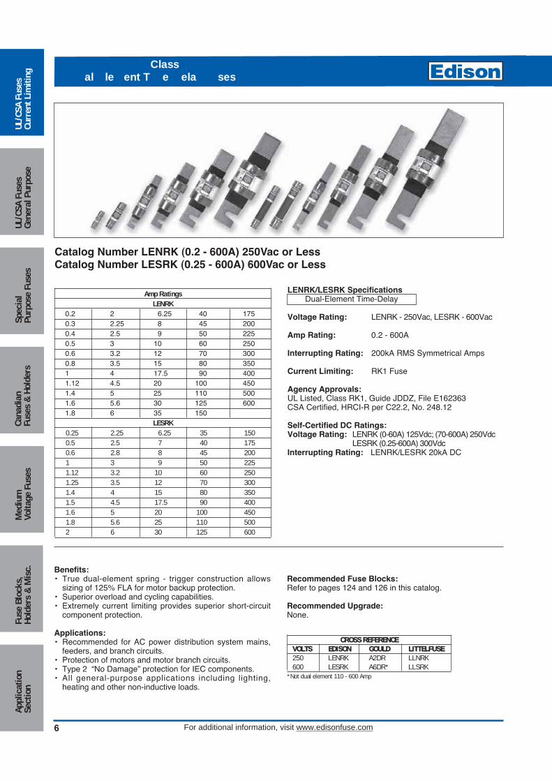
Amp RatingsLENRK
0.2 2 6.25 40 1750.3 2.25 8 45 2000.4 2.5 9 50 2250.5 3 10 60 2500.6 3.2 12 70 3000.8 3.5 15 80 3501 4 17.5 90 4001.12 4.5 20 100 4501.4 5 25 110 5001.6 5.6 30 125 6001.8 6 35 150
LESRK0.25 2.25 6.25 35 1500.5 2.5 7 40 1750.6 2.8 8 45 2001 3 9 50 2251.12 3.2 10 60 2501.25 3.5 12 70 3001.4 4 15 80 3501.5 4.5 17.5 90 4001.6 5 20 100 4501.8 5.6 25 110 5002 6 30 125 600
LENRK/LESRK SpecificationsDual-Element Time-Delay
Voltage Rating: LENRK - 250Vac, LESRK - 600Vac
Amp Rating: 0.2 - 600A
Interrupting Rating: 200kA RMS Symmetrical Amps
Current Limiting: RK1 Fuse
Agency Approvals:UL Listed, Class RK1, Guide JDDZ, File E162363CSA Certified, HRCI-R per C22.2, No. 248.12
Self-Certified DC Ratings:Voltage Rating: LENRK (0-60A) 125Vdc; (70-600A) 250Vdc
LESRK (0.25-600A) 300VdcInterrupting Rating: LENRK/LESRK 20kA DC
Recommended Fuse Blocks:Refer to pages 124 and 126 in this catalog.
Recommended Upgrade:None.
Catalog Number LENRK (0.2 - 600A) 250Vac or LessCatalog Number LESRK (0.25 - 600A) 600Vac or Less
Benefits:• True dual-element spring - trigger construction allows
sizing of 125% FLA for motor backup protection.• Superior overload and cycling capabilities.• Extremely current limiting provides superior short-circuit
component protection.
Applications:• Recommended for AC power distribution system mains,
feeders, and branch circuits.• Protection of motors and motor branch circuits.• Type 2 “No Damage” protection for IEC components.• All general-purpose applications including lighting,
heating and other non-inductive loads.
Med
ium
Volta
ge F
uses
UL/C
SA F
uses
Curr
ent L
imiti
ngUL
/CSA
Fus
esGe
nera
l Pur
pose
Spec
ial
Purp
ose
Fuse
sCa
nadi
anFu
ses
& H
olde
rsAp
plic
atio
nSe
ctio
nFu
se B
lock
s,Ho
lder
s &
Mis
c.
CROSS REFERENCEVOLTS EDISON GOULD LITTELFUSE250 LENRK A2DR LLNRK600 LESRK A6DR* LLSRK
*Not dual element 110 - 600 Amp

Circuit Protection
7
Class al le ent T e ela ses
For additional information, visit www.edisonfuse.com
Overall MaxCatalog Length - in Diameter - inNumber Amps A B
0-30 2 0.5635-60 3 0.81
LENRK70-100 5.88 1.10110-200 7.13 1.61225-400 8.63 2.38450-600 10.38 2.88
0-30 5 0.8135-60 5.5 1.06
LESRK70-100 7.88 1.11110-200 9.63 1.61225-400 11.63 2.36450-600 13.38 2.88
Class R fuses will fit Class H, K and R fuse clips. Class R fuse clips will only accept Class R fuses. Fuses rated 600Vacor less may be applied at any lower voltage. Contact Edison Custom Satisfaction for special products or applications.
Dimensions
Ferrule Design–0 through 60 Amps Knife Blade–70 through 600 Amps
LENRK/LESRK Dual-Element FusesThe application recommended for these fuses is exactly thesame as for the Edison ECNR/ECSR fuses except for theadvantages of greater current limitation. The EdisonLENRK/LESRK fuses have up to 40% more current limitation and up to 350% more Amps-Squared-Second (I2t)limitation under fault conditions than Edison ECNR/ECSRfuses to reduce potential for damage. In addit ion,LENRK/LESRK fuses allow better selectivity for electricalpower system designers and better short-circuit protectionfor breakers having inadequate interrupting ratings.ECNR/ECSR and LENRK/LESRK fuse lines are physicallyinterchangeable (and electrically interchangeable per ULequipment listing conditions) and are recommended as apractical, economical way to upgrade systems for many situations.
True Dual-Element Construction
Insulated end-caps to preventaccidental contact with live parts.
Overload element
Short-circuit element
Medium
Voltage FusesUL/CSA FusesCurrent Lim
itingUL/CSA FusesGeneral Purpose
SpecialPurpose Fuses
CanadianFuses &
HoldersApplicationSection
Fuse Blocks,Holders &
Misc.

8
Class al le ent T e ela ses
For additional information, visit www.edisonfuse.com
Average Melt Time-Current Curves
1/10
2/10
15/1
00
3/10
4/10
6/10
1/2
8/10
11-
1/4
1-6/
102 2-
1/2
3-2/
104 5
6-1/
48 10 12 AMP RATING
300
200
1008060
3040
20
1086
43
1.8.6
.4
.3
.2
.1.08.06.04
2
.01
.03
.02
.1 .2 .3 .4 .6 .8 1 2 3 4 6 8 10 20 30 40 60 80 100
200
300
400
600
800
1,00
0
RMS SYMMETRICAL CURRENT IN AMPS
TIM
E IN
SE
CO
ND
S
LESRK (Amp)
Med
ium
Volta
ge F
uses
UL/C
SA F
uses
Curr
ent L
imiti
ngUL
/CSA
Fus
esGe
nera
l Pur
pose
Spec
ial
Purp
ose
Fuse
sCa
nadi
anFu
ses
& H
olde
rsAp
plic
atio
nSe
ctio
nFu
se B
lock
s,Ho
lder
s &
Mis
c.

Circuit Protection
9
llet Class al le ent T e ela ses
For additional information, visit www.edisonfuse.com
Average Melt Time-Current Curves
LENRK LESRK
RMS SYMMETRICAL CURRENT IN AMPS
TIM
E IN
SE
CO
ND
S
300
200
10080
60
40
30
20
108
6
4
3
2
1.8
.6
.4
.3
.2
.1.08
.06
.04
.03
.02
.01
20 30 40 60 80 100
200
300
400
600
800
1,00
0
2,00
0
3,00
0
4,00
0
6,00
0
8,00
010
,000
20A
60A
100A
200A
30A
400A AMP
RATING600A
15A
Medium
Voltage FusesUL/CSA FusesCurrent Lim
itingUL/CSA FusesGeneral Purpose
SpecialPurpose Fuses
CanadianFuses &
HoldersApplicationSection
Fuse Blocks,Holders &
Misc.

10
Class al le ent T e ela ses
For additional information, visit www.edisonfuse.com
*Curves test data obtained at 15% short-circuit power factor when possible.
INS
TAN
TAN
EO
US
PE
AK
LE
T-T
HR
OU
GH
CU
RR
EN
T IN
AM
PS
400,000
300,000
200,000
100,00080,000
60,000
40,000
30,000
20,000
10,0008,000
6,000
4,000
3,000
2,000
1,000
5,000
50,000
1,00
0
2,00
0
3,00
0
4,00
05,
000
6,00
0
8,00
010
,000
20,0
00
30,0
00
40,0
0050
,000
60,0
00
80,0
0010
0,00
0
200,
000
RMS SYMMETRICAL CURRENTS IN AMPSA–B=ASYMMETRICAL AVAILABLE PEAK (2.3 X SYMM RMS AMPS)
600400
200
10060
30
AMP
RATI
NG
A
B 400,000
300,000
200,000
100,00080,000
60,000
40,000
30,000
20,000
10,0008,000
6,000
4,000
3,000
2,000
1,000
5,000
50,000
1,00
0
2,00
0
3,00
0
4,00
05,
000
6,00
0
8,00
010
,000
20,0
00
30,0
00
40,0
0050
,000
60,0
00
80,0
0010
0,00
0
200,
000
RMS SYMMETRICAL CURRENTS IN AMPSA–B=ASYMMETRICAL AVAILABLE PEAK (2.3 X SYMM RMS AMPS)
600
400
200
10060
30
AMP
RATI
NG
A
B
INS
TAN
TAN
EO
US
PE
AK
LE
T-T
HR
OU
GH
CU
RR
EN
T IN
AM
PS
Peak Let-Through Current Curves*
LENRK LESRK
Current Limtation Tables**
**"Apparent Let-Through Amps" values are read from "Peak Let-Through Current Curves" and the peak current value divided by 2.3 Asymmetry Factor.
LENRK RMS & Peak Let-Through Currents (kA)AvailableFault Apparent Effective Let-Through Amps (kA)current 30 60 100 200 400 600RMS Amps IRMS Ip IRMS Ip IRMS Ip IRMS Ip IRMS Ip IRMS Ip1,000 1 1 1 2 1 2 1 2 1 2 1 22,000 1 2 1 3 2 4 2 5 2 5 2 53,000 1 2 1 3 2 4 3 6 3 7 3 75,000 1 2 2 4 2 5 3 7 5 12 5 1210,000 1 3 2 4 2 6 4 9 7 15 9 2115,000 1 3 2 5 3 6 4 10 7 17 10 2320,000 1 3 2 6 3 7 5 11 8 19 11 2525,000 1 3 3 6 3 7 5 12 9 20 12 2730,000 2 3 3 6 3 8 5 12 9 21 13 2935,000 2 4 3 7 4 8 6 13 10 22 13 3040,000 2 4 3 7 4 9 6 13 10 23 13 3150,000 2 4 3 7 4 9 6 14 10 24 14 3360,000 2 4 3 8 4 10 7 15 11 26 15 3570,000 2 4 3 8 4 10 7 16 12 27 16 3680,000 2 5 4 8 5 11 7 16 12 28 17 3890,000 2 5 4 9 5 11 7 17 13 29 17 39100,000 2 5 4 9 5 11 8 18 13 30 17 40150,000 2 6 4 10 5 13 8 19 16 36 20 46200,000 3 6 5 11 6 14 9 21 18 42 22 50
LESRK RMS & Peak Let-Through Currents (kA)AvailableFault Apparent Effective Let-Through Amps (kA)current 30 60 100 200 400 600RMS Amps IRMS Ip IRMS Ip IRMS Ip IRMS Ip IRMS Ip IRMS Ip1,000 1 1 1 2 1 2 1 2 1 2 1 22,000 1 2 1 3 2 4 2 4 2 4 2 43,000 1 2 1 3 2 4 3 6 3 7 3 75,000 1 2 2 4 2 5 3 7 5 12 5 1210,000 1 3 2 5 3 6 4 9 7 16 9 2115,000 1 3 2 5 3 7 5 11 8 18 10 2420,000 1 3 3 6 3 7 5 12 8 19 11 2625,000 2 4 3 6 3 8 5 12 9 21 12 2830,000 2 4 3 6 4 8 6 13 10 22 13 3035,000 2 4 3 7 4 9 6 14 10 23 13 3140,000 2 4 3 7 4 9 6 14 10 24 14 3250,000 2 5 3 8 4 10 7 15 11 26 15 3560,000 2 5 3 8 4 10 7 16 12 28 16 3770,000 2 5 4 8 5 11 7 17 13 29 17 3980,000 2 5 4 9 5 11 8 18 13 30 17 4090,000 2 5 4 9 5 12 8 18 13 31 18 42100,000 2 6 4 9 5 12 8 19 14 32 19 44150,000 3 6 5 11 6 14 9 21 16 36 22 50200,000 3 7 5 12 7 15 10 23 17 40 23 54
Med
ium
Volta
ge F
uses
UL/C
SA F
uses
Curr
ent L
imiti
ngUL
/CSA
Fus
esGe
nera
l Pur
pose
Spec
ial
Purp
ose
Fuse
sCa
nadi
anFu
ses
& H
olde
rsAp
plic
atio
nSe
ctio
nFu
se B
lock
s,Ho
lder
s &
Mis
c.

Amp RatingsNCLR
1 10 35 80 175 4003 12 40 90 200 4504 15 45 100 225 5005 20 50 110 250 6006 25 60 125 300 —8 30 70 150 350 —
SCLR1 8 30 70 150 3502 10 35 80 175 4003 12 40 90 200 4504 15 45 100 225 5005 20 50 110 250 6006 25 60 125 300 —
NCLR/SCLR SpecificationsFast-Acting
Voltage Rating: NCLR - 250Vac, SCLR - 600Vac
Amp Rating: 1 - 600A
Interrupting Rating: 200kA RMS Symmetrical Amps
Current Limiting: RK1 Fuse
Agency Approvals:UL Listed, Class RK1, Guide JDDZ, File E162363CSA Certified per C22.2, No. 248.12
Self-Certified DC Ratings:Voltage Rating: NCLR (1-600) 250Vdc
SCLR (1-600) 300VdcInterrupting Rating: NCLR/SCLR 10kA DC
Recommended Fuse Blocks:Refer to pages 124 and 126 in this catalog.
Recommended Upgrade:LENRK/LESRK.
Catalog Number NCLR (1- 600A) 250Vac or LessCatalog Number SCLR (1- 600A) 600Vac or Less
Benefits:• No intentional time-delay opens quickly on overload
current.
Applications:• Recommended for protection on non-inductive loads such
as lighting and resistance heating circuits.• Use to protect lower interrupting rating circuit breakers in
series rated applications.
Circuit Protection
11
C Class ast t n sesC Class ast t n ses
For additional information, visit www.edisonfuse.com
Medium
Voltage FusesUL/CSA FusesCurrent Lim
itingUL/CSA FusesGeneral Purpose
SpecialPurpose Fuses
CanadianFuses &
HoldersApplicationSection
Fuse Blocks,Holders &
Misc.
CROSS REFERENCEVOLTS EDISON GOULD LITTELFUSE250 NCLR A2KR KLNR600 SCLR A6KR* KLSR*
* Larger body size on blade type.

Application:Edison NCLR/SCLR Class RK1 fast-acting fuses are recommended for general power distribution system use formain, feeder and branch circuits having a high percentageof non-inductive loads such as heating and lighting.NCLR/SCLR fuses are suitable for circuit breaker protection.* When NCLR/SCLR fast-acting fuses are usedfor inductive loads, the fuses usually require oversizing to override normal transient current surges of motors and
transformers. Oversizing fuses usually increases fuse andequipment cost and reduces overcurrent protection. (Forinductive loads, LENRK/LESRK fuses are recommended).NCLR/SCLR Class RK1 fast-acting fuses are physicallyinterchangeable with other Class R fuses. They will replaceClass K or Class H fuses in standard fuse clips.
*When used as recommended by a specific circuit breaker manufacturer for aspecific application.
Average Time-Current Curves
Cat. No. NCLR (Amp) and SCLR (Amp)
12
C Class ast t n sesC Class ast t n ses
For additional information, visit www.edisonfuse.com
Med
ium
Volta
ge F
uses
UL/C
SA F
uses
Curr
ent L
imiti
ngUL
/CSA
Fus
esGe
nera
l Pur
pose
Spec
ial
Purp
ose
Fuse
sCa
nadi
anFu
ses
& H
olde
rsAp
plic
atio
nSe
ctio
nFu
se B
lock
s,Ho
lder
s &
Mis
c.
RMS SYMMETRICAL CURRENT IN AMPS
TIM
E IN
SE
CO
ND
S
300
200
10080
60
40
30
20
108
6
4
3
2
1.8
.6
.4
.3
.2
.1.08
.06
.04
.03
.02
.01
40 60 80 100
200
300
400
600
800
1,00
0
2,00
0
3,00
0
4,00
0
6,00
0
8,00
010
,000
30A
60A
100A
200A
400A
600A AMP
RATING

Circuit Protection
13
C Class ast t n sesC Class ast t n ses
For additional information, visit www.edisonfuse.com
INS
TAN
TAN
EO
US
PE
AK
LE
T-T
HR
OU
GH
CU
RR
EN
T IN
AM
PS
400,000
300,000
200,000
100,00080,000
60,000
40,000
30,000
20,000
10,0008,000
6,000
4,000
3,000
2,000
1,000
5,000
50,000
1,00
0
2,00
0
3,00
0
4,00
05,
000
6,00
0
8,00
010
,000
20,0
00
30,0
00
40,0
0050
,000
60,0
00
80,0
0010
0,00
0
200,
000
RMS SYMMETRICAL CURRENTS IN AMPSA–B=ASYMMETRICAL AVAILABLE PEAK (2.3 X SYMM RMS AMPS)
600
100
60
AMP
RATI
NG
30
400
200
B
A
200,
000
100,
000
80,0
00
60,0
0050
,000
40,0
00
30,0
00
20,0
00
10,0
008,
000
6,00
05,
000
4,00
0
3,00
0
2,00
0
1,00
01,000
400,000
300,000
200,000
100,00080,000
60,000
40,000
30,000
20,000
10,0008,000
6,000
4,000
3,000
2,000
5,000
50,000
RMS SYMMETRICAL CURRENTS IN AMPSA–B=ASYMMETRICAL AVAILABLE PEAK (2.3 X SYMM RMS AMPS)
600
100
60
AMP
RATI
NG
30
400
200
B
A
INS
TAN
TAN
EO
US
PE
AK
LE
T-T
HR
OU
GH
CU
RR
EN
T IN
AM
PS
Peak Let-Through Current Curves*
NCLR SCLR
Current Limitation Tables**
NCLR SCLR
NCLR – RMS & Peak Let-Through Currents (kA)Prosp. Fuse SizeShort 30 60 100 200 400 600C.C. IRMS Ip IRMS Ip IRMS Ip IRMS Ip IRMS Ip IRMS Ip5,000 1 2 1 3 2 4 3 6 5 10 5 1210,000 1 2 1 3 2 5 3 8 6 14 8 1915,000 1 3 2 4 2 6 4 9 7 17 10 2220,000 1 3 2 4 3 6 4 10 8 19 11 2525,000 1 3 2 5 3 7 4 10 9 20 12 2730,000 1 3 2 5 3 7 5 11 10 22 13 2935,000 1 3 2 5 3 8 5 12 10 23 13 3140,000 1 3 2 5 3 8 5 12 10 24 14 3250,000 2 4 2 5 4 9 6 13 11 26 15 3660,000 2 4 2 6 4 9 6 14 12 28 17 3870,000 2 4 3 6 4 9 6 15 13 29 17 4080,000 2 4 3 6 4 10 7 15 13 30 18 4290,000 2 4 3 6 5 10 7 16 13 31 19 44100,000 2 4 3 7 5 11 7 17 14 32 20 46150,000 2 5 3 7 5 13 8 19 16 37 23 53
200,000 2 5 3 8 6 14 9 21 18 41 26 59
SCLR – RMS & Peak Let-Through Currents (kA)Prosp. Fuse SizeShort 30 60 100 200 400 600C.C. IRMS Ip IRMS Ip IRMS Ip IRMS Ip IRMS Ip IRMS Ip5,000 1 2 1 3 2 4 3 6 5 12 5 1210,000 1 2 2 4 2 5 4 8 7 15 9 2015,000 1 3 2 4 3 6 4 10 8 18 11 2420,000 1 3 2 5 3 7 5 11 9 20 12 2825,000 1 3 2 5 3 7 5 12 10 22 13 3130,000 1 3 2 5 3 8 5 13 10 24 14 3335,000 2 4 2 5 4 8 6 13 11 25 15 3540,000 2 4 2 6 4 9 6 14 11 26 16 3750,000 2 4 3 6 4 9 6 14 12 28 17 4060,000 2 4 3 6 4 10 7 15 13 30 19 4370,000 2 4 3 7 5 10 7 16 14 32 20 4580,000 2 4 3 7 5 11 7 17 14 33 21 4890,000 2 5 3 7 5 12 8 18 15 35 22 50100,000 2 5 3 7 5 12 8 19 16 36 23 52150,000 2 5 4 8 6 14 9 21 18 41 26 60200,000 3 6 4 9 7 15 10 23 20 46 29 66
*Curves test data obtained at 15% short-circuit power factor when possible.
**"Apparent Let-Through Amps" values are read from "Peak Let-Through Current Curves" and the peak current value divided by 2.3 Asymmetry Factor.
Medium
Voltage FusesUL/CSA FusesCurrent Lim
itingUL/CSA FusesGeneral Purpose
SpecialPurpose Fuses
CanadianFuses &
HoldersApplicationSection
Fuse Blocks,Holders &
Misc.

14
Class T e ela sesClass ast t n ses
For additional information, visit www.edisonfuse.com
Amp RatingsLCL
300* 650 801 1350 1800 3500400* 700 900 1400 2000 4000500* 750 1000 1500 2500 —601 800 1200 1600 3000 —
LCU601 800 1350 1800 3000 6000650 1000 1500 2000 3500 —700 1200 1600 2500 4000 —
* Not UL Listed (See note below).
LCL: Time-delay of 5 seconds minimum at 500% rated currentallows closer sizing.
NOTE: LCL 300 - 500 amp fuses are physically the same as 800amp size; Use in 800 amp switch where load current is notfully utilized and a smaller fuse amp size is desired. Alsouseful in new installations to allow for future upgrades inservice.
LCL/LCU SpecificationsLCL: Time-DelayLCU: Fast-Acting
Voltage Rating: LCL - 600Vac, LCU - 600Vac
Amp Rating: LCL: 300 - 4000ALCU: 601 - 6000A
Interrupting Rating: 200kA RMS Symmetrical Amps
Current Limiting: Class L Fuse
Agency Approvals:UL Listed, Class L, Guide JDDZ, File E162363CSA Certified HRC-L per C22.2, No. 248.10
Recommended Sizing:LCL: 150% or more of motor full load current.
Recommended Upgrade:None Available.
Catalog Number LCL (300 - 6000A) Time-Delay 600Vac or LessCatalog Number LCU (601 - 6000A) Fast-Acting 600Vac or Less
Benefits:• “O-ring” construction insures maximum current limiting
ability.• Silver plated micro-peened terminals.• High strength melamine fuse tubes.
Applications:• LCL: Recommended for AC power distribution system
mains and large feeders.• LCU: Recommended for non-inductive heating and
l ighting loads. Also suitable for protection of low interrupting rating circuit breakers.
Med
ium
Volta
ge F
uses
UL/C
SA F
uses
Curr
ent L
imiti
ngUL
/CSA
Fus
esGe
nera
l Pur
pose
Spec
ial
Purp
ose
Fuse
sCa
nadi
anFu
ses
& H
olde
rsAp
plic
atio
nSe
ctio
nFu
se B
lock
s,Ho
lder
s &
Mis
c.
CROSS REFERENCEEDISON GOULD LITTELFUSELCL A4BY KLP-C, KLLULCU None None

Circuit Protection
15
Medium
Voltage FusesUL/CSA FusesCurrent Lim
itingUL/CSA FusesGeneral Purpose
SpecialPurpose Fuses
CanadianFuses &
HoldersApplicationSection
Fuse Blocks,Holders &
Misc.
Class T e ela sesClass ast t n ses
For additional information, visit www.edisonfuse.com
TIM
E IN
SEC
ONDS
AMPRATING80
0A
1200
A16
00A
2000
A30
00A
4000
A
300
100
10
1
.1
.01
1,00
0
10,0
00
100,
000
RMS SYMMETRICAL CURRENT IN AMPSRMS SYMMETRICAL CURRENT IN AMPS
TIM
E IN
SE
CO
ND
S
300
200
10080
60
40
30
20
108
6
4
3
2
1.8
.6
.4
.3
.2
.1.08
.06
.04
.03
.02
.01
2,00
0
1,00
0
3,00
0
4,00
0
6,00
0
8,00
010
,000
20,0
00
30,0
00
40,0
00
60,0
00
80,0
0010
0,00
0
800A
1200
A
1600
A
2000
A
1350
A
3000
A
4000
A
5000
A60
00A
AMPRATING
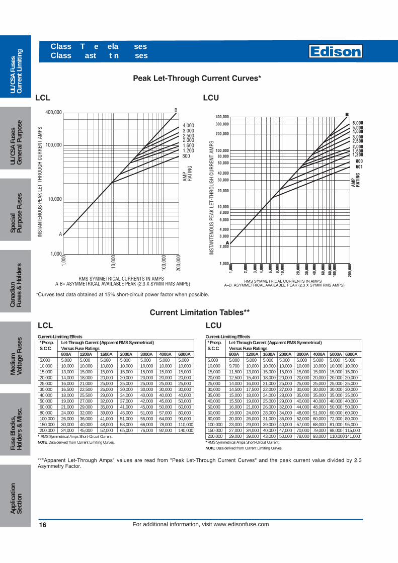
Average Time-Current Curves
Cat. No.LCL (Amp) Cat. No. LCU (Amp)
16
Med
ium
Volta
ge F
uses
UL/C
SA F
uses
Curr
ent L
imiti
ngUL
/CSA
Fus
esGe
nera
l Pur
pose
Spec
ial
Purp
ose
Fuse
sCa
nadi
anFu
ses
& H
olde
rsAp
plic
atio
nSe
ctio
nFu
se B
lock
s,Ho
lder
s &
Mis
c.
Class T e ela sesClass ast t n ses
For additional information, visit www.edisonfuse.com
400,000
300,000
200,000
100,00080,000
60,000
40,000
20,000
30,000
10,0008,000
6,000
4,000
3,000
2,000
1,000
1,00
0
2,00
0
3,00
0
4,00
0
6,00
0
8,00
010
,000
20,0
00
30,0
00
40,0
00
60,0
00
80,0
0010
0,00
0
200,
000
RMS SYMMETRICAL CURRENTS IN AMPSA–B=ASYMMETRICAL AVAILABLE PEAK (2.3 X SYMM RMS AMPS)
A
B
6,0005,0004,0003,0002,5002,0001,6001,200
800601
AMP
RATI
NG
INST
ANTE
NOUS
PEA
K LE
T-TH
ROUG
H CU
RREN
T AM
PS
A
B
4,0003,0002,5002,0001,6001,200800
AMP
RATI
NG
400,000
100,000
10,000
1,000
1,00
0
10,0
00
100,
000
200,
000
RMS SYMMETRICAL CURRENTS IN AMPSA-B= ASYMMETRICAL AVAILABLE PEAK (2.3 X SYMM RMS AMPS)
INST
ANTE
NOUS
PEA
K LE
T-TH
ROUG
H CU
RREN
T AM
PS
Peak Let-Through Current Curves*
LCL LCU
Current Limitation Tables**
LCL LCUCurrent-Limiting Effects*Prosp. Let-Through Current (Apparent RMS Symmetrical)S.C.C. Versus Fuse Ratings
800A 1200A 1600A 2000A 3000A 4000A 6000A5,000 5,000 5,000 5,000 5,000 5,000 5,000 5,00010,000 10,000 10,000 10,000 10,000 10,000 10,000 10,00015,000 13,000 15,000 15,000 15,000 15,000 15,000 15,00020,000 14,000 18,000 20,000 20,000 20,000 20,000 20,00025,000 16,000 21,000 25,000 25,000 25,000 25,000 25,00030,000 16,500 22,500 26,000 30,000 30,000 30,000 30,00040,000 18,000 25,500 29,000 34,000 40,000 40,000 40,00050,000 19,000 27,000 32,000 37,000 42,000 45,000 50,00060,000 21,000 29,000 35,000 41,000 45,000 50,000 60,00080,000 24,000 32,000 39,000 45,000 51,000 57,000 80,000100,000 26,000 36,000 41,000 51,000 55,000 64,000 90,000150,000 30,000 40,000 48,000 58,000 66,000 78,000 110,000200,000 34,000 45,000 52,000 65,000 76,000 92,000 140,000
* RMS Symmetrical Amps Short-Circuit Current.NOTE: Data derived from Current Limiting Curves.
Current-Limiting Effects*Prosp. Let-Through Current (Apparent RMS Symmetrical)S.C.C. Versus Fuse Ratings
800A 1200A 1600A 2000A 3000A 4000A 5000A 6000A5,000 5,000 5,000 5,000 5,000 5,000 5,000 5,000 5,00010,000 9,700 10,000 10,000 10,000 10,000 10,000 10,000 10,00015,000 11,500 13,000 15,000 15,000 15,000 15,000 15,000 15,00020,000 12,500 15,400 18,000 20,000 20,000 20,000 20,000 20,00025,000 14,000 16,000 21,000 25,000 25,000 25,000 25,000 25,00030,000 14,500 17,500 22,000 27,000 30,000 30,000 30,000 30,00035,000 15,000 18,000 24,000 28,000 35,000 35,000 35,000 35,00040,000 15,500 19,000 25,000 29,000 40,000 40,000 40,000 40,00050,000 16,000 21,000 26,000 32,000 44,000 48,000 50,000 50,00060,000 19,000 24,000 28,000 34,000 48,000 51,000 60,000 60,00080,000 20,000 26,000 31,000 36,000 52,000 60,000 72,000 80,000100,000 23,000 29,000 39,000 40,000 57,000 68,000 81,000 95,000150,000 27,000 34,000 40,000 47,000 70,000 79,000 98,000 115,000200,000 29,000 39,000 43,000 50,000 78,000 93,000 110,000141,000
*RMS Symmetrical Amps Short-Circuit Current.NOTE: Data derived from Current Limiting Curves.
**"Apparent Let-Through Amps" values are read from "Peak Let-Through Current Curves" and the peak current value divided by 2.3Asymmetry Factor.
*Curves test data obtained at 15% short-circuit power factor when possible.
Circuit Protection
17
Medium
Voltage FusesUL/CSA FusesCurrent Lim
itingUL/CSA FusesGeneral Purpose
SpecialPurpose Fuses
CanadianFuses &
HoldersApplicationSection
Fuse Blocks,Holders &
Misc.
Class T e ela sesClass ast t n ses
For additional information, visit www.edisonfuse.com
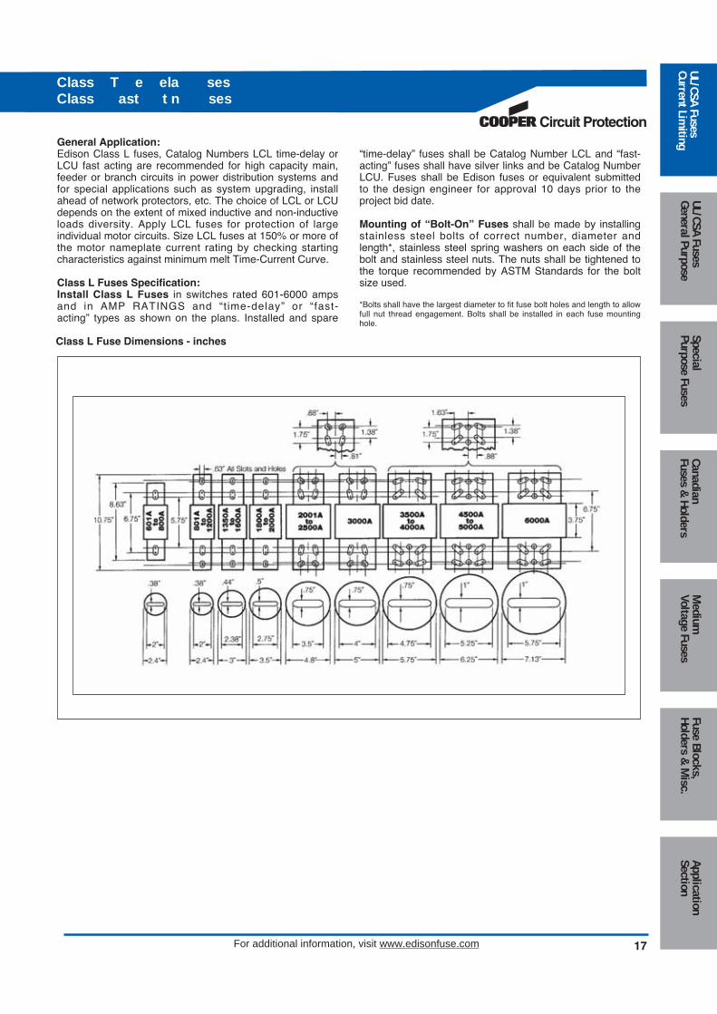
General Application:Edison Class L fuses, Catalog Numbers LCL time-delay orLCU fast acting are recommended for high capacity main,feeder or branch circuits in power distribution systems andfor special applications such as system upgrading, installahead of network protectors, etc. The choice of LCL or LCUdepends on the extent of mixed inductive and non-inductiveloads diversity. Apply LCL fuses for protection of large individual motor circuits. Size LCL fuses at 150% or more ofthe motor nameplate current rating by checking startingcharacteristics against minimum melt Time-Current Curve.
Class L Fuses Specification:Install Class L Fuses in switches rated 601-6000 ampsand in AMP RATINGS and “t ime-delay” or “fast-acting” types as shown on the plans. Installed and spare
“time-delay” fuses shall be Catalog Number LCL and “fast-acting” fuses shall have silver links and be Catalog NumberLCU. Fuses shall be Edison fuses or equivalent submittedto the design engineer for approval 10 days prior to theproject bid date.
Mounting of “Bolt-On” Fuses shall be made by installingstainless steel bolts of correct number, diameter andlength*, stainless steel spring washers on each side of thebolt and stainless steel nuts. The nuts shall be tightened tothe torque recommended by ASTM Standards for the boltsize used.
*Bolts shall have the largest diameter to fit fuse bolt holes and length to allowfull nut thread engagement. Bolts shall be installed in each fuse mountinghole.
Class L Fuse Dimensions - inches

18
Class T e ela ses
For additional information, visit www.edisonfuse.com
Amp RatingsJDL
1 4 12 40 100 2501.25 5 15 45 110 3001.6 5.6 17.5 50 125 3502 6 20 60 150 4002.5 7 25 70 175 4503 8 30 80 200 5003.5 10 35 90 225 600
JDL SpecificationsDual-Element, Time-Delay
Voltage Rating: JDL - 600Vac
Amp Rating: 1 - 600A
Interrupting Rating: 200kA RMS Symmetrical Amps
Current Limiting: Class J Fuse
Agency Approvals:UL Listed, Class J, Guide JDDZ, File E162363CSA Certified per C22.2, No. 248.8
Self-Certified DC Ratings:Voltage Rating: JDL (1-600) 300VdcInterrupting Rating: JDL 20kA DC
Recommend Fuse Blocks:Refer to page 129 in this catalog.
Recommend Upgrade:None.
Catalog Number JDL (1 - 600A) 600Vac or Less
Benefits:• Space saving dimensions vs. Class R.• Dual-Element construction provides superior time-delay
to pass harmless motor or transformer surges.• High performance with fatigue - free cycling capabilities.• Extremely current limiting.
Applications:• Recommended for Type 2 “No Damage” protection of IEC
style motor starters and contactors.• Use to protect lower interrupting rating circuit breakers.• All general purpose circuits with inductive (high inrush)
loads, including motor and motor branch circuits, andtransformer circuits. Also suitable for lighting loads.
Edison JDL Class J fuses are among the most current limiting time-delay fuses available. Their small physical sizeand high performance characteristics makes Class J fusesideal for any space-limited application.
Med
ium
Volta
ge F
uses
UL/C
SA F
uses
Curr
ent L
imiti
ngUL
/CSA
Fus
esGe
nera
l Pur
pose
Spec
ial
Purp
ose
Fuse
sCa
nadi
anFu
ses
& H
olde
rsAp
plic
atio
nSe
ctio
nFu
se B
lock
s,Ho
lder
s &
Mis
c. CROSS REFERENCEEDISON GOULD LITTELFUSE
JDL AJT JTD

Circuit Protection
19
Class T e ela ses
For additional information, visit www.edisonfuse.com
Average Time-Current Curve
Cat. No. JDL (Amp)
Peak Let-Through Current Curves
Cat. No. JDL (Amp)
Current-Limiting Effects
*Prosp. Let-Through Current (Apparent RMS Symmetrical)S.C.C. JDL Fuse Ratings
15A 30A 60A 100A 200A 400A 600A1,000 270 470 750 — — — —±3,000 370 670 1,130 1,640 2,360 — —5,000 450 800 1,420 1,910 2,760 4,400 —10,000 550 1,000 1,730 2,450 3,520 5,540 8,00015,000 625 1,220 1,890 2,850 4,000 6,420 9,00020,000 700 1,330 2,120 3,090 4,400 7,000 10,00025,000 750 1,440 2,250 3,400 5,000 7,500 11,10030,000 800 1,530 2,370 3,650 5,140 8,000 11,80035,000 820 1,600 2,580 3,780 5,430 8,330 12,50040,000 900 1,640 2,670 4,000 5,640 9,000 13,27050,000 925 1,760 2,790 4,470 6,000 9,380 13,82060,000 1,000 1,850 3,000 4,670 6,420 10,000 15,00080,000 1,160 2,000 3,220 5,000 7,400 11,270 16,000100,000 1,220 2,150 3,520 5,360 7,950 12,180 17,270150,000 1,400 2,460 4,000 6,170 9,000 14,360 19,270200,000 1,560 2,640 4,450 7,000 10,000 15,820 20,600
*RMS Symmetrical Amps Short-Circuit Current.NOTE: Data derived from Current Limiting Curves.
300
200
1008060
4030
20
1086
43
2
1.8.6
.4
.3
.2
.1.08.06.04.03
.02
.01
TIM
E IN
SE
CO
ND
S
10,0
008,
000
6,00
0
1,00
0
4,00
03,
000
2,00
0
800
600
400
300
200
100806040302010864321
RMS SYMMETRICAL CURRENT IN AMPS
AmpRating1A 3A 5A 10
A
15A
20A
30A
40A
50A
60A
100A
125A
200A
225A
400A
600A
RMS SYMMETRICAL CURRENTS IN AMPSA–B=ASYMMETRICAL AVAILABLE PEAK (2.3 X SYMM RMS AMPS)
100
200
300
400
600
800
1,00
0
2,00
0
3,00
04,
000
6,00
08,
000
10,0
00
20,0
00
30,0
0040
,000
60,0
0080
,000
100,
000
200,
000
30,000
20,000
10,0008,0006,000
4,0003,000
2,000
1,000800600
400300
200
100
100,00080,00060,000
40,000600400
200100605040302015
AMP
RATI
NG
B
A
INS
TAN
TAN
EO
US
PE
AK
LE
T-T
HR
OU
GH
CU
RR
EN
T IN
AM
PS
INS
TAN
TAN
EO
US
PE
AK
LE
T-T
HR
OU
GH
CU
RR
EN
T IN
AM
PS
100,00080,00060,000
40,00030,000
20,000
10,0008,0006,000
4,0003,000
2,000
1,000800600
400300
200
100
RMS SYMMETRICAL CURRENTS IN AMPSA–B=ASYMMETRICAL AVAILALBE PEAK (2.3 X SYMM RMS AMPS)
100
200
300
400
600
800
1,00
0
2,00
0
3,00
04,
000
6,00
08,
000
10,0
00
20,0
00
30,0
0040
,000
60,0
0080
,000
100,
000
200,
000
107
36
1
AMP
RATI
NG
B
A
DimensionsRefer to JFL Section on page 21.
Medium
Voltage FusesUL/CSA FusesCurrent Lim
itingUL/CSA FusesGeneral Purpose
SpecialPurpose Fuses
CanadianFuses &
HoldersApplicationSection
Fuse Blocks,Holders &
Misc.

20
Class ast t n ses
For additional information, visit www.edisonfuse.com
Amp RatingsJFL
1 8 30 70 150 3502 10 35 80 175 4003 12 40 90 200 4504 15 45 100 225 5005 20 50 110 250 6006 25 60 125 300 —
JFL SpecificationsFast-Acting
Voltage Rating: JFL - 600Vac
Amp Rating: 1 - 600A
Interrupting Rating: 200kA RMS Symmetrical Amps
Current Limiting: Class J Fuse
Agency Approvals:UL Listed, Class J, Guide JDDZ, File E162363CSA Certified per C22.2, No. 248.8
Recommended Fuse Blocks:Refer to page 129 in this catalog.
Recommended Upgrade:JDL.
Catalog Number JFL (1 - 600A) 600Vac or Less
Benefits:• Space saving dimensions vs. Class R.• Fast-acting design permits quick response for both
overloads and shorts.• Extremely current-limiting.
Applications:• Recommended for protection of non-inductive loads, such
as lighting and resistance heating circuits.• For motor applications, refer to Edison JDL.
Edison JFL Class J fuses are among the most currentlimiting fuses available. Their small physical size and highperformance characteristics makes Class J fuses ideal forany space - limited application.Edison JFL fuses are best suited for the protection ofnon-inductive loads such as resistive heating, and lightingcircuits.
Med
ium
Volta
ge F
uses
UL/C
SA F
uses
Curr
ent L
imiti
ngUL
/CSA
Fus
esGe
nera
l Pur
pose
Spec
ial
Purp
ose
Fuse
sCa
nadi
anFu
ses
& H
olde
rsAp
plic
atio
nSe
ctio
nFu
se B
lock
s,Ho
lder
s &
Mis
c. CROSS REFERENCEEDISON GOULD LITTELFUSE
JFL A4J JLS

Circuit Protection
21
Class ast t n ses Class T e ela ses
For additional information, visit www.edisonfuse.com
Average Time-Current CurveCat. No. JFL (Amp)
Peak Let-Through Current Curves**
Current Limitation Table*JFL
RMS SYMMETRICAL CURRENT IN AMPS
TIM
E IN
SE
CO
ND
S
300
200
10080
60
40
30
20
108
6
4
3
2
1.8
.6
.4
.3
.2
.1.08
.06
.04
.03
.02
.01
40 60 80 100
200
300
400
600
800
1,00
0
2,00
0
3,00
0
4,00
0
6,00
0
8,00
010
,000
60A
100A
200A
30A
400A AMP
RATING600A
INS
TAN
TAN
EO
US
PE
AK
LE
T-T
HR
OU
GH
CU
RR
EN
T IN
AM
PS
1,00
0
2,00
0
3,00
0
4,00
05,
000
6,00
0
8,00
010
,000
20,0
00
30,0
00
40,0
0050
,000
60,0
00
80,0
0010
0,00
0
200,
000
400,000
300,000
200,000
100,00080,000
60,000
40,000
30,000
20,000
10,0008,000
6,000
4,000
3,000
2,000
1,000
5,000
50,000
RMS SYMMETRICAL CURRENTS IN AMPSA–B=ASYMMETRICAL AVAILABLE PEAK (2.3 X SYMM RMS AMPS)
600
400
200
AMP
RATI
NG
10060
30
B
A
Amp Overall Max. Blade Barrel Blade BladeRating Length Dia. Length Length Thickness Width Mounting Hole SpacingRange A B C D E F G H J K1-30 2-1/4 13/16 – – – – – – – –35-60 2-3/8 1-1/16 – – – – – – – –70-100 4-5/8 1-1/18 1 2-5/8 1/8 3/4 1/2 3-5/8 3/8 9/32110-200 5-3/4 1-5/8 1-3/8 3 3/16 1-1/8 11/16 4-3/8 3/8 9/32225-400 7-1/8 2-1/8 1-7/8 3-3/8 1/4 1-5/8 15/16 5-1/4 17/32 13/32450-600 8 2-5/8 2-1/8 3-3/4 3/8 2 1 6 11/16 17/32
Prosp. Fuse SizeShort 30 60 100 200 400 600C.C. IRMS Ip IRMS Ip IRMS Ip IRMS Ip IRMS Ip IRMS Ip5,000 1 2 1 3 2 4 3 7 4 10 5 1210,000 1 3 2 4 3 6 4 9 6 13 9 1915,000 1 3 2 4 3 6 4 10 7 15 10 2220,000 1 3 2 5 3 7 5 12 8 18 11 2525,000 2 4 3 6 3 8 6 13 9 19 12 2830,000 2 4 3 6 3 8 6 13 9 20 13 3035,000 2 4 3 7 4 9 6 14 9 21 13 3040,000 2 4 3 7 4 9 7 15 10 22 14 3250,000 2 5 3 8 4 10 7 16 10 23 15 3560,000 2 5 3 8 5 11 7 17 11 25 16 3770,000 2 5 3 8 5 12 8 18 11 25 17 3980,000 2 5 3 8 5 12 8 18 12 28 17 3990,000 2 5 4 9 6 13 9 19 13 29 18 41100,000 2 5 4 9 6 13 9 19 13 30 18 42150,000 2 5 5 11 6 14 9 21 14 33 22 50200,000 3 6 5 12 7 15 10 22 16 37 24 55
Cat No. JFL and JDL Dimensions - inches
* "Apparent Let-Through Amps" values are read from "Peak Let-Through Current Curves" and the peak current value divided by 2.3 Asymmetry Factor.
** Curves test data obtained at 15% short-circuit power factor when possible.
JFL (600Vac)
Medium
Voltage FusesUL/CSA FusesCurrent Lim
itingUL/CSA FusesGeneral Purpose
SpecialPurpose Fuses
CanadianFuses &
HoldersApplicationSection
Fuse Blocks,Holders &
Misc.
22
T a Class T ast t n sesT a Class T ast t n ses
For additional information, visit www.edisonfuse.com
Amp RatingsTJN
1 30 70 150 350 8003 35 80 175 400 10006 40 90 200 450 1200
10 45 100 225 500 —15 50 110 250 600 —20 60 125 300 700 —
TJS1 25 60 125 300 8003 30 70 150 350 —6 35 80 175 400 —
10 40 90 200 450 —15 45 100 225 500 —20 50 110 250 600 —
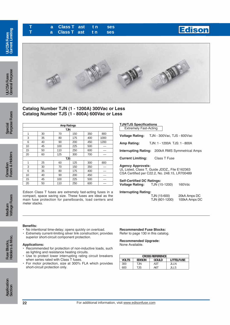
Edison Class T fuses are extremely fast-acting fuses in acompact, space saving size. These fuses are ideal as themain fuse protection for panelboards, load centers andmeter stacks.
TJN/TJS SpecificationsExtremely Fast-Acting
Voltage Rating: TJN - 300Vac, TJS - 600Vac
Amp Rating: TJN: 1 - 1200A TJS: 1 - 800A
Interrupting Rating: 200kA RMS Symmetrical Amps
Current Limiting: Class T Fuse
Agency Approvals:UL Listed, Class T, Guide JDDZ,, File E162363CSA Certified per C22.2, No. 248.15, LR700489
Self-Certified DC Ratings:Voltage Rating: TJN (15-1200) 160Vdc
Interrupting Rating:TJN (15-600) 20kA Amps DCTJN (601-1200) 100kA Amps DC
Recommended Fuse Blocks:Refer to page 130 in this catalog.
Recommended Upgrade:None Available.
Catalog Number TJN (1 - 1200A) 300Vac or LessCatalog Number TJS (1 - 800A) 600Vac or Less
Benefits:• No intentional time-delay; opens quickly on overload.• Extremely current-limiting silver link construction; provides
superior short-circuit component protection.
Applications:• Recommended for protection of non-inductive loads, such
as lighting and resistance heating circuits.• Use to protect lower interrupting rating circuit breakers
when series rated with Class T fuses.• For motor protection, size at 300% FLA which provides
short-circuit protection only.
Med
ium
Volta
ge F
uses
UL/C
SA F
uses
Curr
ent L
imiti
ngUL
/CSA
Fus
esGe
nera
l Pur
pose
Spec
ial
Purp
ose
Fuse
sCa
nadi
anFu
ses
& H
olde
rsAp
plic
atio
nSe
ctio
nFu
se B
lock
s,Ho
lder
s &
Mis
c.
CROSS REFERENCEVOLTS EDISON GOULD LITTELFUSE300 TJN A3T JLLN600 TJS A6T JLLS

Circuit Protection
23
T a Class T ast t n sesT a Class T ast t n ses
For additional information, visit www.edisonfuse.com
RMS SYMMETRICAL CURRENT IN AMPS
TIM
E IN
SE
CO
ND
S
20 30 40 60 80 100
200
300
400
600
800
1,00
0
2,00
0
3,00
0
4,00
0
6,00
0
8,00
010
,000
300
200
10080
60
40
30
20
108
6
4
3
2
1.8
.6
.4
.3
.2
.1.08
.06
.04
.03
.02
.01
60A
100A
200A
30A
400A AMP
RATING600A
15A
INS
TAN
TAN
EO
US
PE
AK
LE
T-T
HR
OU
GH
CU
RR
EN
T IN
AM
PS
RMS SYMMETRICAL CURRENTS IN AMPSA-B = ASYMMETRICAL AVAILABLE PEAK (2.3 x SYMM RMS AMPS)
100,00080,00060,000
40,00030,000
20,000
10,0008,0006,000
4,0003,000
2,000
1,000800600
400300
200
100
200
300
400
600
800
1,00
0
2,00
0
3,00
04,
000
6,00
08,
000
10,0
00
20,0
00
30,0
0040
,000
60,0
0080
,000
100,
000
200,
000
200,000
400,000300,000
600
400200100
603015
AMP
RATI
NG
8001200
B
A
Average Time-Current CurveCat. No. TJN (Amp)
Peak Let-Through Current CurveCat. No. TJN (Amp)
TJN Dimensions - in
0.88˝
0.41˝ Dia.
0.88˝
0.56˝ Dia.
0.84˝1.56˝2.16˝
0.75˝
0.84˝1.69˝2.44˝
0.88˝
0.86˝1.84˝2.75˝
1˝
0.88˝2.03˝3.06˝
1.25˝
0.89˝2.22˝3.38˝
1.75˝
4˝
1.08˝2.53˝
2˝
801 to 1200A
601 to 800A
450 to 600A
1 to 30A
35 to 60A
110 to 200A
225 to 400A
70 to 100A
Medium
Voltage FusesUL/CSA FusesCurrent Lim
itingUL/CSA FusesGeneral Purpose
SpecialPurpose Fuses
CanadianFuses &
HoldersApplicationSection
Fuse Blocks,Holders &
Misc.

24
T a Class T ast t n sesT a Class T ast t n ses
For additional information, visit www.edisonfuse.com
Average Time-Current CurveCat. No. TJS (Amp)
Peak Let-Through Current CurveCat. No. TJS (Amp)
800
RMS SYMMETRICAL CURRENTS IN AMPSA–B=ASYMMETRICAL AVAILABLE PEAK (2.3 X SYMM RMS AMPS)
100,00080,00060,000
40,00030,000
20,000
10,0008,0006,000
4,0003,000
2,000
1,000
600
400300
200
100
200
300
400
600
800
1,00
0
2,00
0
3,00
04,
000
6,00
08,
000
10,0
00
20,0
00
30,0
0040
,000
60,0
0080
,000
100,
000
200,
000
200,000
400,000300,000
600
400
20010060
30
AMP
RATI
NG
8001200
B
AINS
TAN
TAN
EO
US
PE
AK
LE
T-T
HR
OU
GH
CU
RR
EN
T IN
AM
PS
10,0
008,
000
6,00
0
1,00
0
4,00
03,
000
2,00
0
800
600
400
300
200
100806040302010864321
300
200
1008060
4030
20
1086
43
2
1.8.6
.4
.3
.2
.1.08.06.04.03
.02
.01
CURRENT IN AMPS
TIM
E IN
SE
CO
ND
S
1A 3A 5A 10A
30A
15A
60A
200A
400A
500A
100A
800A AMP
RATING
TJS Dimensions - inches
3.98"(± 0.04)
2.95"1.78"
1.25"(± 0.04)
450A to 600A
3.63"(± 0.04)
2.72"1.73"
1"(± 0.04)
225A to 400A
601A to 800A
4.33"(± 0.04)3.17"1.88"
1.75"(± 0.04)
0.88"(± 0.04)
3.25"(± 0.04)
2.5"1.66"
110A to 200A
Dia. 0.56"(± 0.04)
1A to 30A
1.5"(± 0.04)
Dia. 0.81"(± 0.04)
0.75"(± 0.04)
2.95"(± 0.04)
2.36"1.64"
70A to 100A
0.344"(Typ. 2)
0.563"(Typ. 2)
0.484"(Typ. 2)
0.406"(Typ. 2)
0.281"(Typ. 2)
1.00"(± 0.01)
Med
ium
Volta
ge F
uses
UL/C
SA F
uses
Curr
ent L
imiti
ngUL
/CSA
Fus
esGe
nera
l Pur
pose
Spec
ial
Purp
ose
Fuse
sCa
nadi
anFu
ses
& H
olde
rsAp
plic
atio
nSe
ctio
nFu
se B
lock
s,Ho
lder
s &
Mis
c.

Amp RatingsSEC
.5 3 8 25 451 4 10 30 501.5 5 15 35 602 6 20 40 —
Dimensions - inchesAmps Ferrule Diameter Length
1 - 15 0.41 1.3120 0.41 1.4125 - 30 0.41 1.6335 - 60 0.41 2.25
SEC SpecificationsFast-Acting; Time-Delay*
Voltage Rating: SEC 0.5 to 20 600VacSEC 25 to 60 480Vac
Amp Rating: 0.5 to 6A (fast-acting), 7 to 60A (time-delay)
Interrupting Rating: 100kA RMS Symmetrical Amps
Current Limiting: Class G Fuse
Agency Approvals:UL Listed, Std. 248-5, Class G, Guide JDDZ, File E162363CSA Certified, C22.2 No. 248.5, Class 1422-01, File700489
Self-Certified DC Ratings:Voltage Rating: SEC (0.5-20A) 170Vdc;
SEC (30 and 60A only) 300VdcInterrupting Rating: 10kA Amps DC*Fast-acting/time-delay varies by amp rating
Recommended Fuse Blocks:Refer to page 132 in this catalog.
Recommended Upgrade:None Available.
Catalog Number SEC (0.5 - 60A) 600Vac or Less
Benefits:• Branch circuit rated for 480Vac.• Compact size features varying length rejection feature
which helps prevent overfusing.• Time-delay of 12 sec. min. at 200% rating for amp sizes
6 through 60.
Applications:• General purpose for use in 120/208 and 277/480 circuits.
Ideal for fluorescent fixture protection.• Light inductive loads including motors, solenoids, etc.
(For additional delay, refer to Edison EDCC or JDL).
Circuit Protection
25
C T e aClass ses
For additional information, visit www.edisonfuse.com
Medium
Voltage FusesUL/CSA FusesCurrent Lim
itingUL/CSA FusesGeneral Purpose
SpecialPurpose Fuses
CanadianFuses &
HoldersApplicationSection
Fuse Blocks,Holders &
Misc.
CROSS REFERENCEEDISON GOULD LITTELFUSE
SEC AG SLC

Peak Let-Through Current CurveCat. No. SEC (Amp)
Average Time-Current CurveCat. No. SEC (Amp)
100
10
1
.1
.01
.1 1 10 100
1000
CURRENT IN AMPS
TIM
E IN
SE
CO
ND
S
.5 1 3 4 6 8 10 15 20 25 30
AMPRATING
10,0008,0006,000
4,0003,000
2,000
1,000800600
400
200
300
100
100
200
300
400
2,00
0
2,00
0
600
800
1,00
0
4,00
0
6,00
08,
000
10,0
00
20,0
00
30,0
0040
,000
60,0
0080
,000
100,
000
INS
TAN
TAN
EO
US
PE
AK
LE
T- T
HR
OU
GH
CU
RR
EN
T IN
AM
PS
B 60
302015
AMP
RATI
NG
A
RMS SYMMETRICAL CURRENTS IN AMPSA–B=ASYMMETRICAL AVAILABLE PEAK (2.3 X SYMM RMS AMPS)
26
C T e aClass ses
For additional information, visit www.edisonfuse.com
Med
ium
Volta
ge F
uses
UL/C
SA F
uses
Curr
ent L
imiti
ngUL
/CSA
Fus
esGe
nera
l Pur
pose
Spec
ial
Purp
ose
Fuse
sCa
nadi
anFu
ses
& H
olde
rsAp
plic
atio
nSe
ctio
nFu
se B
lock
s,Ho
lder
s &
Mis
c.
Circuit Protection
27
CC T e elaC CC ses
For additional information, visit www.edisonfuse.com
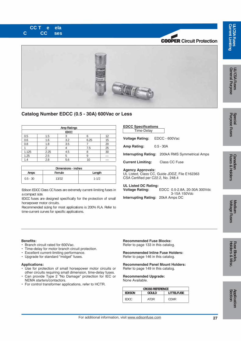
Amp RatingsEDCC
0.5 1.5 3 6 120.6 1.6 3.2 6.25 150.8 1.8 3.5 7 201 2 4 7.5 251.125 2.25 4.5 8 301.25 2.5 5 9 —1.4 2.8 5.6 10 —
Dimensions - inchesAmps Ferrule Length
0.5 - 30 13/32 1-1/2
Edison EDCC Class CC fuses are extremely current-limiting fuses ina compact size. EDCC fuses are designed specifically for the protection of smallhorsepower motor circuits.Recommended sizing for most applications is 200% FLA. Refer totime-current curves for specific applications.
EDCC SpecificationsTime-Delay
Voltage Rating: EDCC - 600Vac
Amp Rating: 0.5 - 30A
Interrupting Rating: 200kA RMS Symmetrical Amps
Current Limiting: Class CC Fuse
Agency Approvals:UL Listed, Class CC, Guide JDDZ, File E162363CSA Certified per C22.2, No. 248.4
UL Listed DC Rating:Voltage Rating: EDCC 0.5-2.8A, 20-30A 300Vdc
3-15A 150VdcInterrupting Rating: 20kA Amps DC
Recommended Fuse Blocks:Refer to page 133 in this catalog.
Recommended Inline Fuse Holders:Refer to page 146 in this catalog.
Recommended Panel Mount Holders:Refer to page 149 in this catalog.
Recommended Upgrade:None Available.
Catalog Number EDCC (0.5 - 30A) 600Vac or Less
Benefits:• Branch circuit rated for 600Vac.• Time-delay for motor branch circuit protection.• Excellent current-limiting performance.• Upgrade for standard “midget” fuses.
Applications:• Use for protection of small horsepower motor circuits or
other circuits requiring small dimension, time-delay fuses.• Can provide Type 2 “No Damage” protection for IEC or
NEMA starters/contactors.• For control transformer applications, refer to HCTR.
Medium
Voltage FusesUL/CSA FusesCurrent Lim
itingUL/CSA FusesGeneral Purpose
SpecialPurpose Fuses
CanadianFuses &
HoldersApplicationSection
Fuse Blocks,Holders &
Misc.
CROSS REFERENCEEDISON GOULD LITTELFUSE
EDCC ATDR CCMR
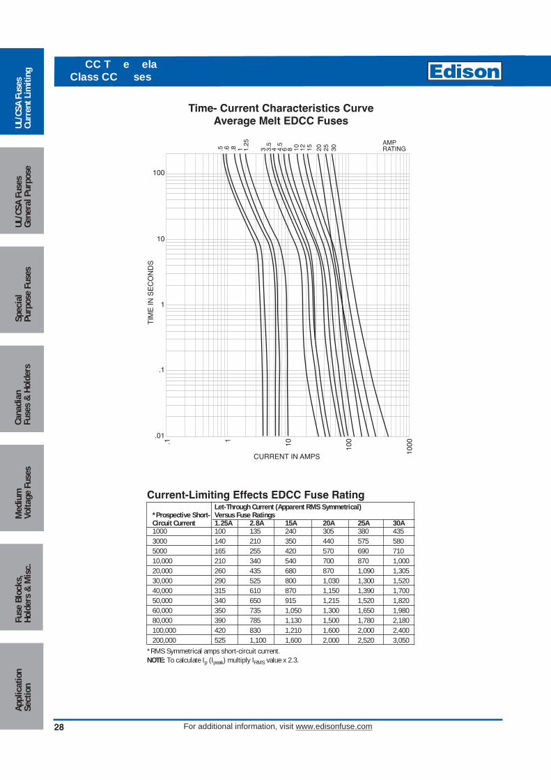
28
CC T e elaClass CC ses
For additional information, visit www.edisonfuse.com
100
10
1
.1
.01
.1 1 10 100
1000
CURRENT IN AMPS
TIM
E IN
SE
CO
ND
S
.5 .6 .8 1 1.25
3 3.5
4 4.5
6 8 10 12 15 20 25 30
AMPRATING
Current-Limiting Effects EDCC Fuse RatingLet-Through Current (Apparent RMS Symmetrical)
*Prospective Short- Versus Fuse RatingsCircuit Current 1.25A 2.8A 15A 20A 25A 30A1000 100 135 240 305 380 4353000 140 210 350 440 575 5805000 165 255 420 570 690 71010,000 210 340 540 700 870 1,00020,000 260 435 680 870 1,090 1,30530,000 290 525 800 1,030 1,300 1,52040,000 315 610 870 1,150 1,390 1,70050,000 340 650 915 1,215 1,520 1,82060,000 350 735 1,050 1,300 1,650 1,98080,000 390 785 1,130 1,500 1,780 2,180100,000 420 830 1,210 1,600 2,000 2,400200,000 525 1,100 1,600 2,000 2,520 3,050
*RMS Symmetrical amps short-circuit current.NOTE: To calculate Ip (Ipeak) multiply IRMS value x 2.3.
Time- Current Characteristics CurveAverage Melt EDCC Fuses
Med
ium
Volta
ge F
uses
UL/C
SA F
uses
Curr
ent L
imiti
ngUL
/CSA
Fus
esGe
nera
l Pur
pose
Spec
ial
Purp
ose
Fuse
sCa
nadi
anFu
ses
& H
olde
rsAp
plic
atio
nSe
ctio
nFu
se B
lock
s,Ho
lder
s &
Mis
c.

Circuit Protection
C ast t n Class CC sesCT T e ela Class CC ses
For additional information, visit www.edisonfuse.com 29
Amp Ratings0.1 0.5 2.5 6 120.125 0.75 3 7 150.2 1 3.5 8 200.25 1.5 4 9 250.3 2 5 10 30
Dimensions - inchesAmps Ferrule Length
0.1 - 30 13/32 1-1/2
HCLR SpecificationsFast-Acting
Voltage Rating: HCLR - 600Vac
Amp Rating: 0.1 - 30A
Interrupting Rating: 200kA RMS Symmetrical Amps
Current Limiting: Class CC Fuse
Agency Approvals:UL Listed, Class CC, Guide JDDZ, File E162363CSA Certified per C22.2, No. 248.4
Benefits:• Branch circuit rated for 600Vac.• Compact dimensions.• Fast-acting design responds quickly to both overload and
short-circuit current.
Applications:• Lighting and resistive heating loads.
Recommended Fuse Blocks:Refer to page 133 in this catalog.
Recommended Inline Fuse Holders:Refer to page 146 in this catalog.
Recommended Panel Mount Holders:Refer to page 149 in this catalog.
Catalog Number HCLR (0.1 - 30A) 600Vac or LessFast-Acting
Amp Ratings0.25 0.75 1.3 2 3.2 6.25 120.3 0.8 1.4 2.25 3.5 7.5 150.4 1 1.5 2.5 4 8 200.5 1.125 1.6 2.8 5 9 250.6 1.25 1.8 3 6 10 30
Dimensions - inchesAmps Ferrule Length
0.25 - 30 13/32 1-1/2
HCTR SpecificationsTime-Delay
Voltage Rating: HCTR - 600Vac
Amp Rating: 0.25 - 30A
Interrupting Rating: 200kA RMS Symmetrical Amps
Current Limiting: Class CC Fuse
Agency Approvals:UL Listed, Class CC, Guide JDDZ, File E162363CSA Certified per C22.2, No. 248.4
Benefits:• Branch circuit rated for 600Vac.• Compact dimensions.• Time-delay design allows closer sizing for inductive loads
such as control transformers and solenoids.
Applications:• Primary protection for control transformers.
Recommended Fuse Blocks:Refer to page 133 in this catalog.
Recommended Inline Fuse Holders:Refer to page 146 in this catalog.
Recommended Panel Mount Holders:Refer to page 149 in this catalog.
Catalog Number HCTR (0.25 - 30A) 600Vac or LessTime-Delay
Medium
Voltage FusesUL/CSA FusesCurrent Lim
itingUL/CSA FusesGeneral Purpose
SpecialPurpose Fuses
CanadianFuses &
HoldersApplicationSection
Fuse Blocks,Holders &
Misc.
CROSS REFERENCEEDISON GOULD LITTELFUSE
HCLR ATMR KLKR
CROSS REFERENCEEDISON GOULD LITTELFUSE
HCTR ATQR KLDR
Circuit Protection

30
C ast t n Class CC sesCT T e ela Class CC ses
For additional information, visit www.edisonfuse.com
RMS SYMMETRICAL CURRENT IN AMPS
TIM
E IN
SE
CO
ND
S
300
200
100
80
60
40
30
20
10
8
6
4
3
2
1
.8
.6
.4
.3
.2
.1
.08
.06
.04
.03
.02
.01 2 3 4 6 8 10 20 30 40 60 80 100
200
300
4001
10A
20A
3A
AMPRATING2A1A 5A 8A 15
A
Average Time-Current CurveCat. No. HCLR (Amp) Fast-Acting Cat. No. HCTR (Amp) Time-Delay
1/2
1 3 5 7-1/
2 AMPRATING
.4 .6 .8 1 2 3 4 6 8 10 20 30 40 60 80 100
200
RMS SYMMETRICAL CURRENT IN AMPS
100
80
60
30
40
20
10
8
6
4
3
1
.8
.6
.4
.3
.2
.1.08
.06
.04
2
.01
.03
.02
TIM
E IN
SE
CO
ND
S
Med
ium
Volta
ge F
uses
UL/C
SA F
uses
Curr
ent L
imiti
ngUL
/CSA
Fus
esGe
nera
l Pur
pose
Spec
ial
Purp
ose
Fuse
sCa
nadi
anFu
ses
& H
olde
rsAp
plic
atio
nSe
ctio
nFu
se B
lock
s,Ho
lder
s &
Mis
c.

Circuit Protection
31For additional information, visit www.edisonfuse.com
Catalog No. MCL (0.1 - 30A) 600Vac or LessFast-Acting
Amp RatingsMCL
0.1 0.75 3.5 9 300.125 1 4 10 —0.2 1.5 5 12 —0.25 2 6 15 —0.3 2.5 7 20 —0.5 3 8 25 —
Dimensions - inchesAmps Ferrule Length
0.1 - 30 13/32 1-1/2
MCL SpecificationsFast-Acting
Voltage Rating: 600Vac
Amp Rating: 0.1 - 30A
Interrupting Rating: 100kA RMS Amps
Agency Approvals:(0.1 - 30) UL Listed, File E162443 (0.1 - 30) CSA Cert., LR700489
Benefits:• Compact dimensions.• High interrupting rating.• Fast-acting design responds quickly
to both overloads and short-circuitcurrent.
Applications:• Street lighting holders, HID lighting,
control circuits, electronic equipmentprotection.
Catalog No. MOL (0.5 - 30A) 250Vac or LessFast-Acting
Amp RatingsMOL
0.5 2.5 6 10 251 3 6.5 12 301.5 4 8 15 —2 5 9 20 —
Dimensions - inchesAmps Ferrule Length
0.5 - 30 13/32 1-1/2
MOL SpecificationsFast-Acting
Voltage Rating: 0.5-15A, 250Vac20-30A, 125Vac
Amp Rating: 0.5 - 30A
Interrupting Rating: 10kA @ 125Vac 20-30A35A @ 250Vac 0.5-1A100A@ 250Vac 1.5-6A200A@ 250Vac 6.5-10A750A @ 250Vac 12-15A
Agency Approvals:(0.5 - 30) UL Listed, File E162443 (0.5 - 30) CSA Cert., LR700489
Benefits:• Compact dimensions.• Economical laminated paper tube
design.
Applications:• Supplemental protection for non-
inductive control and l ighting circuits.
Catalog No. EBS (0.2 - 10A) 0.2 - 5A 600Vac or Less6 - 10A 250Vac or LessFast-Acting
Amp RatingsEBS
0.2 0.8 1.8 5 100.4 1 2 6 —0.5 1.5 3 7 —0.75 1.6 4 8 —
Dimensions - inchesAmps Ferrule Length
0.2 - 10 13/32 1-3/8
EBS SpecificationsFast-Acting
Voltage Rating: 0.2-5A, 600Vac6-10A, 250Vac
Amp Rating: 0.2 - 10A
Interrupting Rating: 10kA RMS Amps
Agency Approvals:UL Listed, File E162443CSA Cert., LR700489
Benefits:• Compact dimensions.• Shorter than standard midget
dimensions.• Economical design.
Applications:• Supplemental protection for
non-inductive control and lighting circuits.
Recommended Panel Mount Holders:Refer to page 149 in this catalog.
et sesast t n
Recommended Fuse Blocks: Pages 134 & 150. Recommended Inline FuseHolders: Page 146. Recommended Panel Mount Holders: Page 149.
Medium
Voltage FusesUL/CSA FusesCurrent Lim
itingUL/CSA FusesGeneral Purpose
SpecialPurpose Fuses
CanadianFuses & Holders
ApplicationSection
Fuse Blocks,Holders & M
isc.
CROSS REFERENCEEDISON GOULD LITTELFUSEMCL ATM KLK
CROSS REFERENCEEDISON GOULD LITTELFUSEMOL OTM BLF
CROSS REFERENCEEDISON GOULD LITTELFUSEEBS None BLS

6
4
3
2
1.8
.6
.4
.3
.2
.1.08
.06
.04
.03
.02
.01
.05
.5
5
1 2 3 4 5 6 8 10 20 30 40 50 60 80 100
200
300
400
500
600
800
1,00
0
108
20
30
405060
80100
RMS SYMMETRICAL CURRENT IN AMPS
TIM
E IN
SE
CO
ND
S
AMPRATING4/
10A
3/4A
1A 2A 3A 6A 7A
6
4
3
2
1.8
.6
.4
.3
.2
.1.08
.06
.04
.03
.02
.01
.05
.5
5
1 2 3 4 5 6 8 10 20 30 40 50 60 80 100
200
300
400
500
600
800
1,00
0
108
20
30
40506080
100
RMS SYMMETRICAL CURRENT IN AMPS
TIM
E IN
SE
CO
ND
S
AMPRATING3A 10
A
1A 15A
20A
30A
RMS SYMMETRICAL CURRENT IN AMPS
TIM
E IN
SE
CO
ND
S
300
200
100
80
60
40
30
20
10
8
6
4
3
2
1
.8
.6
.4
.3
.2
.1
.08
.06
.04
.03
.02
.01 2 3 4 6 8 10 20 30 40 60 80 100
200
300
4001
10A
20A
3A
AMPRATING2A1A 5A 8A 15
A
Average Time-Current Curve
Cat. No. MCL (Amp) Cat. No. MOL (Amp)
32 For additional information, visit www.edisonfuse.com
Cat. No. EBS (Amp)
et sesast t n
Med
ium
Volta
ge F
uses
UL/C
SA F
uses
Curr
ent L
imiti
ngUL
/CSA
Fus
esGe
nera
l Pur
pose
Spec
ial
Purp
ose
Fuse
sCa
nadi
anFu
ses
& Ho
lder
sAp
plic
atio
nSe
ctio
nFu
se B
lock
s,Ho
lder
s &
Mis
c.
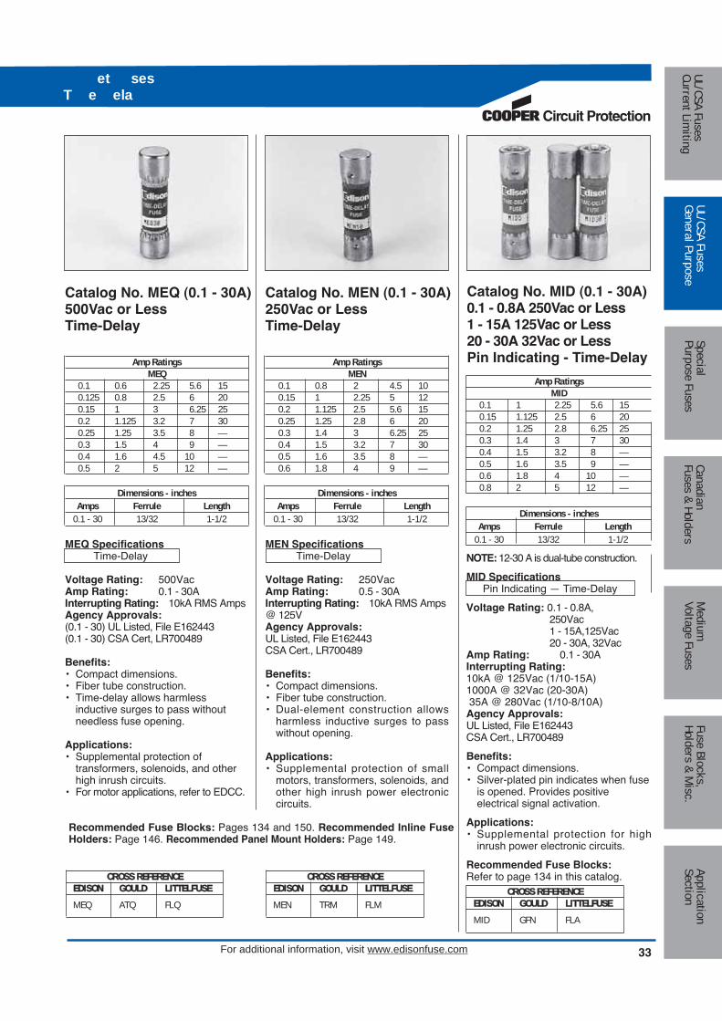
Circuit Protection
For additional information, visit www.edisonfuse.com 33
Catalog No. MEQ (0.1 - 30A) 500Vac or LessTime-Delay
Amp RatingsMEQ
0.1 0.6 2.25 5.6 150.125 0.8 2.5 6 200.15 1 3 6.25 250.2 1.125 3.2 7 300.25 1.25 3.5 8 —0.3 1.5 4 9 —0.4 1.6 4.5 10 —0.5 2 5 12 —
Dimensions - inchesAmps Ferrule Length
0.1 - 30 13/32 1-1/2
MEQ SpecificationsTime-Delay
Voltage Rating: 500VacAmp Rating: 0.1 - 30AInterrupting Rating: 10kA RMS AmpsAgency Approvals:(0.1 - 30) UL Listed, File E162443(0.1 - 30) CSA Cert, LR700489
Benefits:• Compact dimensions.• Fiber tube construction.• Time-delay allows harmless
inductive surges to pass withoutneedless fuse opening.
Applications:• Supplemental protection of
transformers, solenoids, and otherhigh inrush circuits.
• For motor applications, refer to EDCC.
Catalog No. MEN (0.1 - 30A) 250Vac or LessTime-Delay
Amp RatingsMEN
0.1 0.8 2 4.5 100.15 1 2.25 5 120.2 1.125 2.5 5.6 150.25 1.25 2.8 6 200.3 1.4 3 6.25 250.4 1.5 3.2 7 300.5 1.6 3.5 8 —0.6 1.8 4 9 —
Dimensions - inchesAmps Ferrule Length
0.1 - 30 13/32 1-1/2
MEN SpecificationsTime-Delay
Voltage Rating: 250VacAmp Rating: 0.5 - 30AInterrupting Rating: 10kA RMS Amps@ 125VAgency Approvals:UL Listed, File E162443CSA Cert., LR700489
Benefits:• Compact dimensions.• Fiber tube construction.• Dual-element construction allows
harmless inductive surges to passwithout opening.
Applications:• Supplemental protection of small
motors, transformers, solenoids, andother high inrush power electroniccircuits.
Catalog No. MID (0.1 - 30A) 0.1 - 0.8A 250Vac or Less1 - 15A 125Vac or Less20 - 30A 32Vac or LessPin Indicating - Time-Delay
Amp RatingsMID
0.1 1 2.25 5.6 150.15 1.125 2.5 6 200.2 1.25 2.8 6.25 250.3 1.4 3 7 300.4 1.5 3.2 8 —0.5 1.6 3.5 9 —0.6 1.8 4 10 —0.8 2 5 12 —
Dimensions - inchesAmps Ferrule Length
0.1 - 30 13/32 1-1/2
NOTE: 12-30 A is dual-tube construction.
MID SpecificationsPin Indicating — Time-Delay
Voltage Rating: 0.1 - 0.8A,250Vac1 - 15A,125Vac20 - 30A, 32Vac
Amp Rating: 0.1 - 30AInterrupting Rating:10kA @ 125Vac (1/10-15A) 1000A @ 32Vac (20-30A)35A @ 280Vac (1/10-8/10A)Agency Approvals:UL Listed, File E162443CSA Cert., LR700489
Benefits:• Compact dimensions.• Silver-plated pin indicates when fuse
is opened. Provides positive electrical signal activation.
Applications:• Supplemental protection for high
inrush power electronic circuits.
Recommended Fuse Blocks:Refer to page 134 in this catalog.
et sesT e ela
Recommended Fuse Blocks: Pages 134 and 150. Recommended Inline FuseHolders: Page 146. Recommended Panel Mount Holders: Page 149.
Medium
Voltage FusesUL/CSA FusesCurrent Lim
itingUL/CSA FusesGeneral Purpose
SpecialPurpose Fuses
CanadianFuses & Holders
ApplicationSection
Fuse Blocks,Holders & M
isc.
CROSS REFERENCEEDISON GOULD LITTELFUSEMID GFN FLA
CROSS REFERENCEEDISON GOULD LITTELFUSEMEQ ATQ FLQ
CROSS REFERENCEEDISON GOULD LITTELFUSEMEN TRM FLM

6
4
3
2
1.8
.6
.4
.3
.2
.1.08
.06
.04
.03
.02
.01
.05
.5
5
1 2 3 4 5 6 8 10 20 30 40 50 60 80 100
200
300
400
500
600
800
1,00
0
108
20
30
405060
80100
RMS SYMMETRICAL CURRENT IN AMPS
TIM
E IN
SE
CO
ND
S
AMPRATING1/
2A
1A
6
4
3
2
1.8
.6
.4
.3
.2
.1.08
.06
.04
.03
.02
.01
.05
.5
5
1 2 3 4 5 6 8 10 20 30 40 50 60 80 100
200
300
400
500
600
800
1,00
0
108
20
30
40506080
100
RMS SYMMETRICAL CURRENT IN AMPS
TIM
E IN
SE
CO
ND
S
AMPRATING3A2A1A 15
A
20A
1/2A
5A 10A
Cat. No. MID (Amp)
34 For additional information, visit www.edisonfuse.com
et sesT e ela
Med
ium
Volta
ge F
uses
UL/C
SA F
uses
Curr
ent L
imiti
ngUL
/CSA
Fus
esGe
nera
l Pur
pose
Spec
ial
Purp
ose
Fuse
sCa
nadi
anFu
ses
& Ho
lder
sAp
plic
atio
nSe
ctio
nFu
se B
lock
s,Ho
lder
s &
Mis
c.
1/2
1 3 5 7-1/
2 AMPRATING
.4 .6 .8 1 2 3 4 6 8 10 20 30 40 60 80 100
200
RMS SYMMETRICAL CURRENT IN AMPS
100
80
60
30
40
20
10
8
6
4
3
1
.8
.6
.4
.3
.2
.1.08
.06
.04
2
.01
.03
.02
TIM
E IN
SE
CO
ND
S
Average Time-Current Curve
Cat. No. MEN (Amp) Cat. No. MEQ (Amp)

Circuit Protection
35For additional information, visit www.edisonfuse.com
Amp RatingsKON 250Vac
1 7 25 60 125 3002 8 30 70 150 3503 10 35 80 175 4004 12 40 90 200 4505 15 45 100 225 5006 20 50 110 250 600
KOS 600Vac1 7 25 60 125 3002 8 30 70 150 3503 10 35 80 175 4004 12 40 90 200 4505 15 45 100 225 5006 20 50 110 250 600
Self-Certified DC Ratings:Voltage Rating: KON (1-600A) 250Vdc
KOS (1-30A) 600VdcKOS (35-60A) 300VdcKOS (70-600A) 600Vdc
Interrupting Rating: 10kA DC @ Rated Voltage
KON/KOS Specifications“One-Time”, Fast-Acting
Voltage Rating: KON - 250Vac, KOS - 600Vac
Amp Rating: 1 - 600A
Interrupting Rating:KON 1-60A Class K5 50kA RMS Symmetrical AmpsKON 70-600A Class H 10kA RMS Symmetrical AmpsKOS 1-12A Class H 10kA RMS Symmetrical AmpsKOS 15-60A Class K5 50kA RMS Symmetrical AmpsKOS 70-600A Class H 10kA RMS Symmetrical Amps
Agency Approvals:UL Listed, Class K5, UL248-9, File E162363UL Listed, Class H, UL248-6, File E162363CSA Certified* HRC-K5 per C22.22, No. 248.9, LR700489CSA Certified HRC-H per C22.22, No. 248.6, LR700489
*NOTE: KON15 - 60A are not CSA Certified. Refer to PONCfor use in CANADA.
Recommended Fuse Blocks:Refer to pages 123 and 126 in this catalog.
Recommended Upgrade:ECNR/ECSR or LENRK/LESRK.
Catalog Number KON (1 - 600A) 250Vac or LessCatalog Number KOS (1 - 600A) 600Vac or Less
Benefits:• Economical, for general purpose use.
Applications:• Lighting or heating circuits not subject to high levels of
inrush current.• Circuits having relatively low levels of available
short-circuit current.• For motor applications, refer to Edison ECNR/ECSR.
Class an ne T e ses Class an ne T e ses
Medium
Voltage FusesUL/CSA FusesCurrent Lim
itingUL/CSA FusesGeneral Purpose
SpecialPurpose Fuses
CanadianFuses & Holders
ApplicationSection
Fuse Blocks,Holders & M
isc.CROSS REFERENCEEDISON GOULD LITTELFUSEKON OT NLNKOS OTS NLS
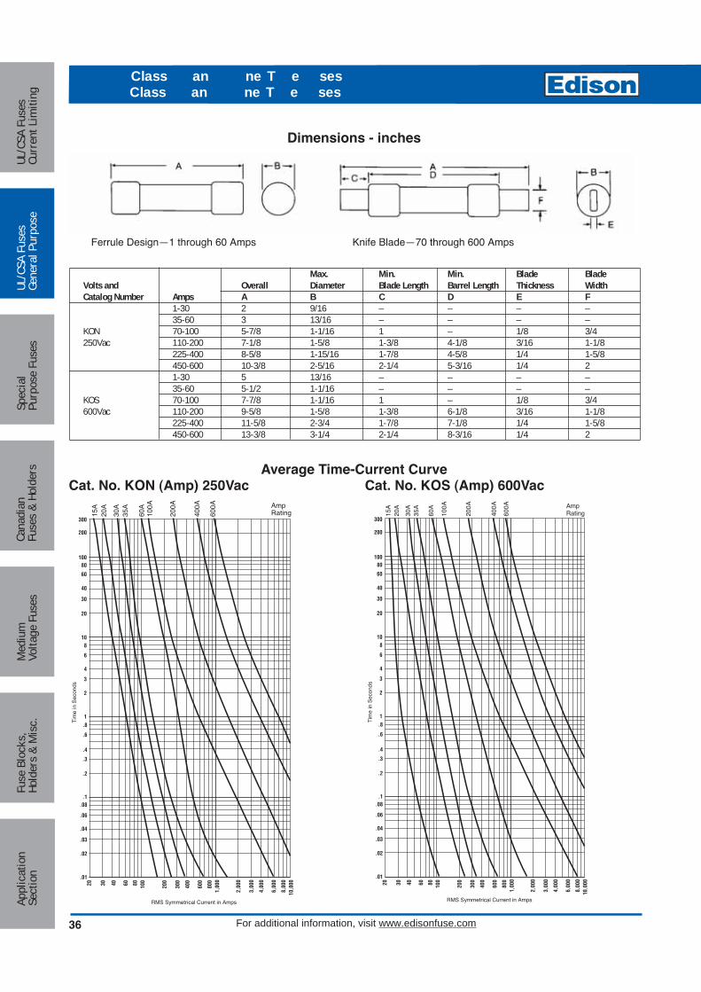
36 For additional information, visit www.edisonfuse.com
Dimensions - inches
Max. Min. Min. Blade BladeVolts and Overall Diameter Blade Length Barrel Length Thickness WidthCatalog Number Amps A B C D E F
1-30 2 9/16 – – – –35-60 3 13/16 – – – –
KON 70-100 5-7/8 1-1/16 1 – 1/8 3/4250Vac 110-200 7-1/8 1-5/8 1-3/8 4-1/8 3/16 1-1/8
225-400 8-5/8 1-15/16 1-7/8 4-5/8 1/4 1-5/8450-600 10-3/8 2-5/16 2-1/4 5-3/16 1/4 21-30 5 13/16 – – – –35-60 5-1/2 1-1/16 – – – –
KOS 70-100 7-7/8 1-1/16 1 – 1/8 3/4600Vac 110-200 9-5/8 1-5/8 1-3/8 6-1/8 3/16 1-1/8
225-400 11-5/8 2-3/4 1-7/8 7-1/8 1/4 1-5/8450-600 13-3/8 3-1/4 2-1/4 8-3/16 1/4 2
Ferrule Design—1 through 60 Amps Knife Blade—70 through 600 Amps
RMS Symmetrical Current in Amps
Tim
e in
Sec
onds
20 30 40 60 80 100
200
300
400
600
800
1,00
0
2,00
0
3,00
0
4,00
0
6,00
0
8,00
010
,000
300
200
10080
60
40
30
20
108
6
4
3
2
1.8
.6
.4
.3
.2
.1.08
.06
.04
.03
.02
.01
60A
100A
200A
30A
400A Amp
Rating600A
15A
35A
20A
RMS Symmetrical Current in Amps
Tim
e in
Sec
onds
20 30 40 60 80 100
200
300
400
600
800
1,00
0
2,00
0
3,00
0
4,00
0
6,00
0
8,00
010
,000
300
200
10080
60
40
30
20
108
6
4
3
2
1.8
.6
.4
.3
.2
.1.08
.06
.04
.03
.02
.01
60A
100A
200A
30A
400A Amp
Rating600A
15A
35A
20A
Average Time-Current CurveCat. No. KON (Amp) 250Vac Cat. No. KOS (Amp) 600Vac
Class an ne T e ses Class an ne T e ses
Med
ium
Volta
ge F
uses
UL/C
SA F
uses
Curr
ent L
imiti
ngUL
/CSA
Fus
esGe
nera
l Pur
pose
Spec
ial
Purp
ose
Fuse
sCa
nadi
anFu
ses
& Ho
lder
sAp
plic
atio
nSe
ctio
nFu
se B
lock
s,Ho
lder
s &
Mis
c.
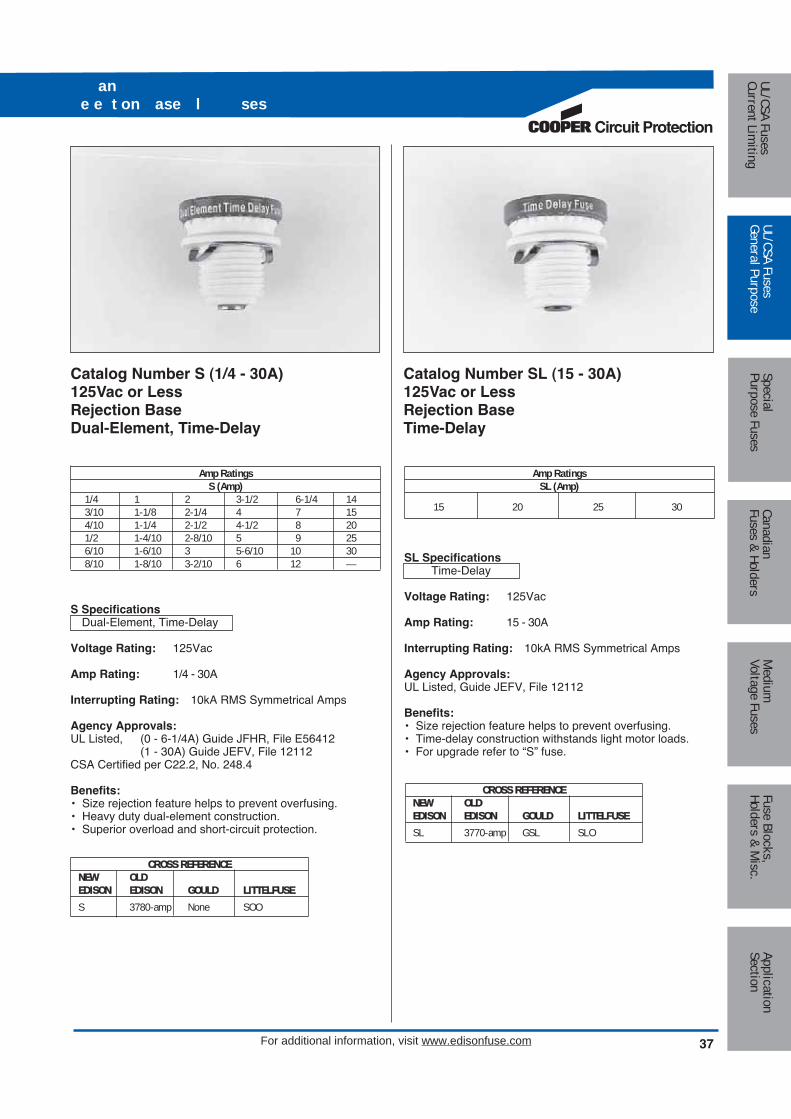
Amp RatingsS (Amp)
1/4 1 2 3-1/2 6-1/4 143/10 1-1/8 2-1/4 4 7 154/10 1-1/4 2-1/2 4-1/2 8 201/2 1-4/10 2-8/10 5 9 256/10 1-6/10 3 5-6/10 10 308/10 1-8/10 3-2/10 6 12 —
S SpecificationsDual-Element, Time-Delay
Voltage Rating: 125Vac
Amp Rating: 1/4 - 30A
Interrupting Rating: 10kA RMS Symmetrical Amps
Agency Approvals:UL Listed, (0 - 6-1/4A) Guide JFHR, File E56412
(1 - 30A) Guide JEFV, File 12112CSA Certified per C22.2, No. 248.4
Benefits:• Size rejection feature helps to prevent overfusing.• Heavy duty dual-element construction.• Superior overload and short-circuit protection.
Catalog Number S (1/4 - 30A) 125Vac or LessRejection BaseDual-Element, Time-Delay
Amp RatingsSL (Amp)
15 20 25 30
SL SpecificationsTime-Delay
Voltage Rating: 125Vac
Amp Rating: 15 - 30A
Interrupting Rating: 10kA RMS Symmetrical Amps
Agency Approvals:UL Listed, Guide JEFV, File 12112
Benefits:• Size rejection feature helps to prevent overfusing.• Time-delay construction withstands light motor loads.• For upgrade refer to “S” fuse.
Catalog Number SL (15 - 30A) 125Vac or LessRejection BaseTime-Delay
Medium
Voltage FusesUL/CSA FusesCurrent Lim
itingUL/CSA FusesGeneral Purpose
SpecialPurpose Fuses
CanadianFuses & Holders
ApplicationSection
Fuse Blocks,Holders & M
isc.CROSS REFERENCENEW OLDEDISON EDISON GOULD LITTELFUSES 3780-amp None SOO
CROSS REFERENCENEW OLDEDISON EDISON GOULD LITTELFUSESL 3770-amp GSL SLO
Circuit Protection
37For additional information, visit www.edisonfuse.com
an e e t on ase l ses

38 For additional information, visit www.edisonfuse.com
Amp RatingsW (Amp)
1/2 2 4 6-1/2 101 2-1/2 5 7 121-8/10 3 6 8 —
W SpecificationsFast-Acting
Voltage Rating: 125Vac
Amp Rating: 1/2 - 12A
Interrupting Rating: 10kA RMS Symmetrical Amps
Agency Approvals:UL Listed, Guide JEFV, File E 12112
Benefits:• General purpose for non-inductive lighting and heating
loads.• Economical.• Edison base threads into non-rejection fuse receptacles.
Obsoleted W-15 through W-30 plug fuses are replaced withT and TL plug fuses.
Recommended Box Cover Units:Refer to page 136 in this catalog.
Catalog Number W (1/2 - 12A) 125Vac or LessEdison BaseFast-Acting Adapter Sizes
SA (Amp)1 2 4 8 201-1/4 2-1/2 4-1/2 10 301-6/10 3-2/10 6-1/4 15 —
Rejection base fuses (Type S and SL) require adapters tobe used in standard Edison base sockets. Once installed,rejection base adapters accept only rejection base fuseswhich prevents the wrong fuse size from being used.
Dual-Element Type S Fuses and Adapters for Small MotorProtection. (Both Motor Running and Short-Circuit Protection)
Fuse Adapter Other AcceptedCat. No. Cat. No. Amp RatingS3/10, S1/2, S8/10 SA-1 1 amp and smallerS4/10, S6/10, S1S1-1/8, S1-1-1/4 SA-1-1/4 All smallerS1-4/10, S1-6/10 SA-1-6/10 All smallerS1-8/10, S2 SA-2 —S2-1/4, S2-1/2 SA-2-1/2 1-8/10, 2S2-8/10, S3-2/10 SA-3-2/10 1-8/10 thru 2-1/2S3-1/2, S4 SA-4 —S4-1/2, S5 SA-4-1/2 3-1/2, 4S5-6/10, S6-1/4 SA-6-1/4 3-1/2 thru 5S7, S8 SA-8 —S9, S10 SA-10 7, 8S12, S14 SA-15 7, 8, 9, 10
Branch Circuit ProtectionS15 SA-15 —S20 SA-20 —S25 SA-30 —S30 SA-30 20, 25, 30
Catalog Number SA (1 - 30A) Rejection Base Fuse Adapter
son ase l sesan se a te s
Med
ium
Volta
ge F
uses
UL/C
SA F
uses
Curr
ent L
imiti
ngUL
/CSA
Fus
esGe
nera
l Pur
pose
Spec
ial
Purp
ose
Fuse
sCa
nadi
anFu
ses
& Ho
lder
sAp
plic
atio
nSe
ctio
nFu
se B
lock
s,Ho
lder
s &
Mis
c.
CROSS REFERENCENEW OLDEDISON EDISON GOULD LITTELFUSEW 3765-amp GW WOO CROSS REFERENCE
NEW OLDEDISON EDISON GOULD LITTELFUSESA ESA None SAO

Circuit Protection
39For additional information, visit www.edisonfuse.com
Amp RatingsT (Amp)
3/10 1-1/8 2-1/4 4 7 154/10 1-1/4 2-1/2 4-1/2 8 201/2 1-4/10 2-8/10 5 9 256/10 1-6/10 3 5-6/10 10 308/10 1-8/10 3-2/10 6 12 —1 2 3-1/2 6-1/4 14 —
T SpecificationsDual-Element, Time-Delay
Voltage Rating: 125Vac
Amp Rating: 3/10 - 30A
Interrupting Rating: 10kA RMS Symmetrical Amps
Agency Approvals:UL Listed, Guide JEFV, File E 12112
Benefits:• Heavy duty dual-element construction for motor circuits.• Edison base threads into non-rejection fuse receptacles.• Superior overload and short-circuit protection.
Recommended Box Cover Units:Refer to page 136 in this catalog.
Catalog Number T (3/10 - 30A) 125Vac or LessEdison BaseDual-Element, Time-Delay
Amp RatingsTL (Amp)
15 20 25 30
TL SpecificationsTime-Delay
Voltage Rating: 125Vac
Amp Rating: 15 - 30A
Interrupting Rating: 10kA RMS Symmetrical Amps
Agency Approvals:UL Listed, Guide JEFV, File 12112
Benefits:• Time-delay construction withstands light motor loads.• Edison base threads into non-rejection fuse receptacles.• For upgrade refer to “T” fuse.
Recommended Box Cover Units:Refer to page 136 in this catalog.
Catalog Number TL (15 - 30A) 125Vac or LessEdison BaseTime-Delay
T an Tson ase l ses
Medium
Voltage FusesUL/CSA FusesCurrent Lim
itingUL/CSA FusesGeneral Purpose
SpecialPurpose Fuses
CanadianFuses & Holders
ApplicationSection
Fuse Blocks,Holders & M
isc.CROSS REFERENCENEW OLDEDISON EDISON GOULD LITTELFUSET 3785-amp GT TOO
CROSS REFERENCENEW OLDEDISON EDISON GOULD LITTELFUSETL 3740-amp GTL TLO

For additional information, visit www.edisonfuse.com40
TC an son ase l ses
Catalog Number TC (15 - 30A)125 Volts AC or LessEdison BaseDual-Element, Time-Delay
Amp RatingsP (Amp)
15 20 25 30
P Specifications
Dual-Element, One-Time
Voltage Rating: 125Vac
Amp Rating: 15 - 30A
Benefits:• For non-inductive loads.• Edison base threads into non-rejection fuse receptacles.
Recommended Box Cover Units:Refer to page 136 in this catalog.
Catalog Number P (15 - 30A)125 Volts AC or LessEdison BaseDual-Element, One-Time
Amp RatingsTC (Amp)
15 20 25 30
TC Specifications
Dual-Element, Time-Delay
Voltage Rating: 125Vac
Amp Rating: 15 - 30A
Agency Information:CSA Certified (Class 1423-01, File # 53787)
Benefits:• “D” rating for Canadian applications.• Heavy Duty TC fuses are industrial strength products,
featuring Bussmann’s exclusive Dual-Element construction.
• This spring loaded design provides superior short-circuitand overload protection.
• The TC fuses have more time-delay than the mediumduty fuses in order to better protect industrial motors andoptical residential circuits.
Recommended Box Cover Units:Refer to page 136 in this catalog.
Med
ium
Volta
ge F
uses
UL/C
SA F
uses
Curr
ent L
imiti
ngUL
/CSA
Fus
esGe
nera
l Pur
pose
Spec
ial
Purp
ose
Fuse
sCa
nadi
anFu
ses
& Ho
lder
sAp
plic
atio
nSe
ctio
nFu
se B
lock
s,Ho
lder
s &
Mis
c.
CROSS REFERENCENEW OLDEDISON EDISON GOULD LITTELFUSET 3785-amp GT TOO
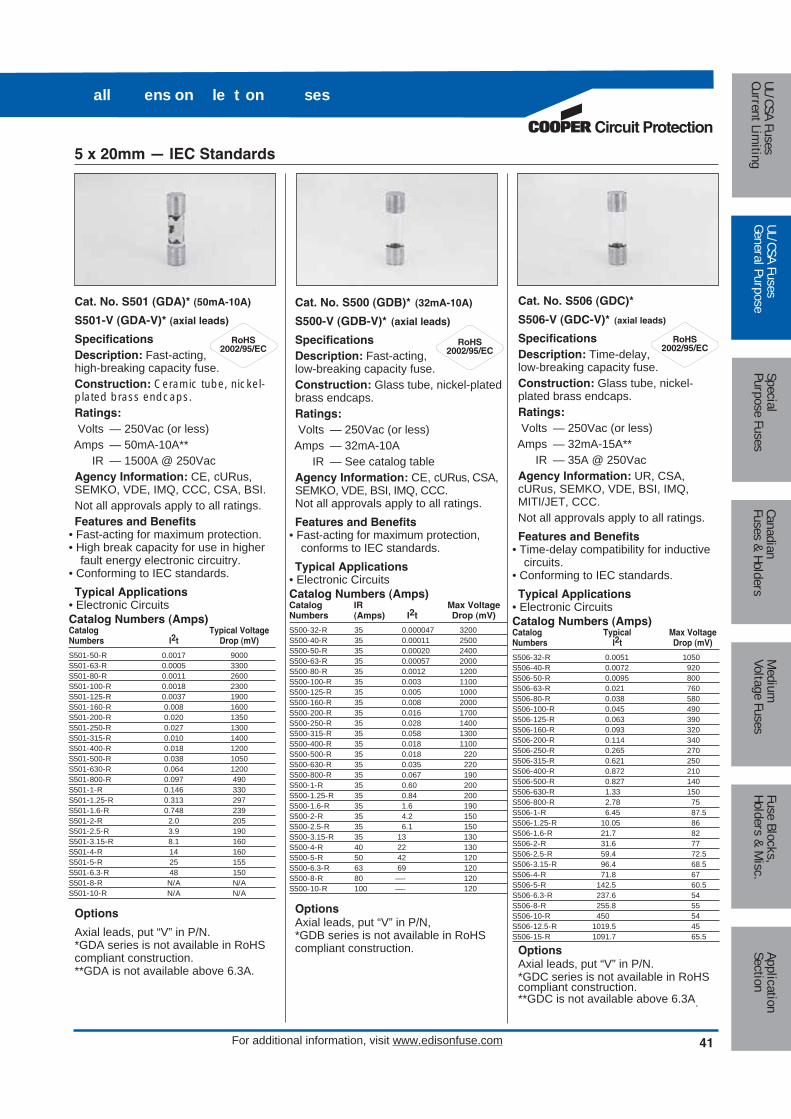
Circuit Protection
For additional information, visit www.edisonfuse.com 41
Cat. No. S501 (GDA)* (50mA-10A)
S501-V (GDA-V)* (axial leads)
SpecificationsDescription: Fast-acting,high-breaking capacity fuse.Construction: Ceramic tube, nickel-plated brass endcaps.Ratings:Volts — 250Vac (or less)
Amps — 50mA-10A**IR — 1500A @ 250Vac
Agency Information: CE, cURus,SEMKO, VDE, IMQ, CCC, CSA, BSI.Not all approvals apply to all ratings. Features and Benefits
• Fast-acting for maximum protection.• High break capacity for use in higher
fault energy electronic circuitry.• Conforming to IEC standards.Typical Applications
• Electronic CircuitsCatalog Numbers (Amps)Catalog Typical VoltageNumbers I2t Drop (mV)
S501-50-R 0.0017 9000S501-63-R 0.0005 3300S501-80-R 0.0011 2600S501-100-R 0.0018 2300S501-125-R 0.0037 1900S501-160-R 0.008 1600S501-200-R 0.020 1350S501-250-R 0.027 1300S501-315-R 0.010 1400S501-400-R 0.018 1200S501-500-R 0.038 1050S501-630-R 0.064 1200S501-800-R 0.097 490S501-1-R 0.146 330S501-1.25-R 0.313 297S501-1.6-R 0.748 239S501-2-R 2.0 205S501-2.5-R 3.9 190S501-3.15-R 8.1 160S501-4-R 14 160S501-5-R 25 155S501-6.3-R 48 150S501-8-R N/A N/AS501-10-R N/A N/A
Options
Axial leads, put “V” in P/N.*GDA series is not available in RoHScompliant construction. **GDA is not available above 6.3A.
Cat. No. S500 (GDB)* (32mA-10A)
S500-V (GDB-V)* (axial leads)
SpecificationsDescription: Fast-acting,low-breaking capacity fuse.Construction: Glass tube, nickel-platedbrass endcaps.Ratings:Volts — 250Vac (or less)
Amps — 32mA-10AIR — See catalog table
Agency Information: CE, cURus, CSA,SEMKO, VDE, BSI, IMQ, CCC.Not all approvals apply to all ratings.Features and Benefits
• Fast-acting for maximum protection,conforms to IEC standards.
Typical Applications• Electronic CircuitsCatalog Numbers (Amps)Catalog IR Max VoltageNumbers (Amps) I2t Drop (mV)
S500-32-R 35 0.000047 3200S500-40-R 35 0.00011 2500S500-50-R 35 0.00020 2400S500-63-R 35 0.00057 2000S500-80-R 35 0.0012 1200S500-100-R 35 0.003 1100S500-125-R 35 0.005 1000S500-160-R 35 0.008 2000S500-200-R 35 0.016 1700S500-250-R 35 0.028 1400S500-315-R 35 0.058 1300S500-400-R 35 0.018 1100S500-500-R 35 0.018 220S500-630-R 35 0.035 220S500-800-R 35 0.067 190S500-1-R 35 0.60 200S500-1.25-R 35 0.84 200S500-1.6-R 35 1.6 190S500-2-R 35 4.2 150S500-2.5-R 35 6.1 150S500-3.15-R 35 13 130S500-4-R 40 22 130S500-5-R 50 42 120S500-6.3-R 63 69 120S500-8-R 80 —- 120S500-10-R 100 —- 120
OptionsAxial leads, put “V” in P/N, *GDB series is not available in RoHScompliant construction.
Cat. No. S506 (GDC)*
S506-V (GDC-V)* (axial leads)
SpecificationsDescription: Time-delay,low-breaking capacity fuse.Construction: Glass tube, nickel-plated brass endcaps.Ratings:Volts — 250Vac (or less)
Amps — 32mA-15A**IR — 35A @ 250Vac
Agency Information: UR, CSA,cURus, SEMKO, VDE, BSI, IMQ,MITI/JET, CCC.Not all approvals apply to all ratings.Features and Benefits
• Time-delay compatibility for inductivecircuits.
• Conforming to IEC standards.Typical Applications
• Electronic CircuitsCatalog Numbers (Amps)Catalog Typical Max VoltageNumbers I2t Drop (mV)
S506-32-R 0.0051 1050S506-40-R 0.0072 920S506-50-R 0.0095 800S506-63-R 0.021 760S506-80-R 0.038 580S506-100-R 0.045 490S506-125-R 0.063 390S506-160-R 0.093 320S506-200-R 0.114 340S506-250-R 0.265 270S506-315-R 0.621 250S506-400-R 0.872 210S506-500-R 0.827 140S506-630-R 1.33 150S506-800-R 2.78 75S506-1-R 6.45 87.5S506-1.25-R 10.05 86S506-1.6-R 21.7 82S506-2-R 31.6 77S506-2.5-R 59.4 72.5S506-3.15-R 96.4 68.5S506-4-R 71.8 67S506-5-R 142.5 60.5S506-6.3-R 237.6 54S506-8-R 255.8 55S506-10-R 450 54S506-12.5-R 1019.5 45S506-15-R 1091.7 65.5
OptionsAxial leads, put “V” in P/N. *GDC series is not available in RoHScompliant construction. **GDC is not available above 6.3A.
all ens on le t on ses
5 x 20mm — IEC Standards
Medium
Voltage FusesUL/CSA FusesCurrent Lim
itingUL/CSA FusesGeneral Purpose
SpecialPurpose Fuses
CanadianFuses & Holders
ApplicationSection
Fuse Blocks,Holders & M
isc.

42 For additional information, visit www.edisonfuse.com
all ens on le t on ses
Cat. No. GMA (63mA-15A)
GMA-V (axial leads)
SpecificationsDescription:Fast-acting fuseConstruction: Glass tube,nickel-plated brass endcaps.Agency Information: CE, Std.248-14 UL Listed Guide JDYX, FileE19180, 0-6A, UL Recognized, GuideJDYX2, File E19180, 7-15A, CSACertified, Class 1422-01,File E65063, 0-6.
Catalog RatedNumber Voltage Vac IR (amps)(amps) (Vac) 250 125GMA-63-R 35 10,000GMA-100-R 35 10,000GMA-125-R 35 10,000GMA-200-R 35 10,000GMA-250-R 35 10,000GMA-300-R 35 10,000GMA-500-R 35 10,000GMA-600-R 35 10,000GMA-750-R 250 35 10,000GMA-800-R 35 10,000GMA-1-R 35 10,000GMA-1.25-R 100 10,000GMA-1.5-R 100 10,000GMA-1.6-R 100 10,000GMA-2-R 100 10,000GMA-2.5-R 100 10,000GMA-3.15-R – 10,000GMA-3.5-R – 10,000GMA-4-R – 10,000GMA-5-R – 10,000GMA-6-R 125 – 10,000GMA-7-R – 200GMA-8-R – 200GMA-10-R – 150GMA-15-R – 150
Cat. No. GMC (50mA-10A)
GMC-V (axial leads)
SpecificationsDescription: Mediumtime-delay fuse.Construction: Glass tube, nickel-plated brass endcaps.
Agency Information: CE, Std. 248-14, UL Listed Guide JDYX, FileE19180, 0-6.3A, UL Recognized,Guide JDYX2, File E19180, 7-8A,CSA Certified, Class 1422-01, File65063, 0-6.3A.
Catalog RatedNumber Voltage Vac IR (amps)(amps) (Vac) 250 125GMC-63mA 35 10,000GMC-80mA 35 10,000GMC-100mA 35 10,000GMC-125mA 35 10,000GMC-150mA 35 10,000GMC-200mA 35 10,000GMC-250mA 35 10,000GMC-300mA 35 10,000GMC-315mA 35 10,000GMC-400mA 35 10,000GMC-500-R 35 10,000GMC-600-R 250 35 10,000GMC-630-R 35 10,000GMC-750-R 35 10,000GMC-800-R 35 10,000GMC-1-R 35 10,000GMC-1.25-R 100 10,000GMC-1.5-R 100 10,000GMC-1.6-R 100 10,000GMC-2-R 100 10,000GMC-2.5-R 100 10,000GMC-3.15-R 100 10,000GMC-3.5-R – 10,000GMC-4-R – 10,000GMC-5-R – 10,000GMC-6-R – 10,000GMC-6.3-R 125 – 200GMC-7-R – 200GMC-8-R – 200GMC-10-R – 200
Cat. No. GMD (125mA-4A)
GMD-V (axial leads)
SpecificationsDescription: Time-delayfuse.Construction: Glass tube, nickel-plated brass endcaps.Agency Information: CE, UL ListedGuide JDYX, File E19180, 125mA-3A, UL Recognized, GuideJDYX2, File E19180, 4A, CSACertified, Class 1422-01, File 53787,0-4A, PSE/JET,File 1641-31003-1001, 1.2A-4A.
Catalog RatedNumber Voltage Vac IR (amps)(amps) (Vac) 250 125GMD-125-R 35 10,000GMD-150-R 35 10,000GMD-200-R 35 10,000GMD-250-R 35 10,000GMD-300-R 35 10,000GMD-315-R 35 10,000GMD-375-R 35 10,000GMD-400-R 35 10,000GMD-500-R 35 10,000GMD-600-R 35 10,000GMD-630-R 35 10,000GMD-750-R 250 35 10,000GMD-800-R 35 10,000GMD-1-R 35 10,000GMD-1.2-R 100 10,000GMD-1.25-R 100 10,000GMD-1.5-R 100 10,000GMD-1.6-R 100 10,000GMD-2-R 100 10,000GMD-2.5-R 100 10,000GMD-3-R 100 10,000GMD-4-R 200 10,000
5 x 20mm — N. American Standards
OptionsAxial leads, put “V” in P/N. Options
Axial leads, put “V” in P/N.
OptionsAxial leads, put “V” in P/N.
Med
ium
Volta
ge F
uses
UL/C
SA F
uses
Curr
ent L
imiti
ngUL
/CSA
Fus
esGe
nera
l Pur
pose
Spec
ial
Purp
ose
Fuse
sCa
nadi
anFu
ses
& Ho
lder
sAp
plic
atio
nSe
ctio
nFu
se B
lock
s,Ho
lder
s &
Mis
c.
CROSS REFERENCENEW OLDEDISON EDISON GOULD LFGMA BMA GGM 235
CROSS REFERENCENEW OLDEDISON EDISON GOULD LFGMC — GSC None
CROSS REFERENCENEW OLDEDISON EDISON GOULD LFGMD — None 239
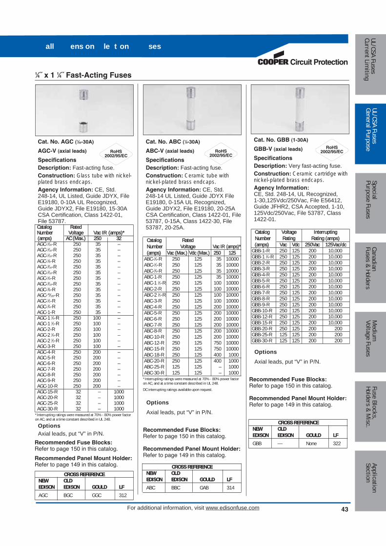
Circuit Protection
43For additional information, visit www.edisonfuse.com
Cat. No. ABC (1⁄4-30A)
ABC-V (axial leads)
SpecificationsDescription: Fast-acting fuse.Construction: Ceramic tube withnickel-plated brass endcaps.Agency Information: CE, Std. 248-14 UL Listed, Guide JDYX FileE19180, 0-15A UL Recognized,Guide JDYX2, File E19180, 20-25ACSA Certification, Class 1422-01, File53787, 0-15A, Class 1422-30, File53787, 20-25A.
Catalog RatedNumber Voltage Vac IR (amps)*(amps) Vac (Max.) Vdc (Max.) 250 125
ABC-1⁄4-R 250 125 35 10000ABC-1⁄2-R 250 125 35 10000ABC-3⁄4-R 250 125 35 10000ABC-1-R 250 125 35 10000ABC-1 1⁄2-R 250 125 100 10000ABC-2-R 250 125 100 10000ABC-2 1⁄2-R 250 125 100 10000ABC-3-R 250 125 100 10000ABC-4-R 250 125 200 10000ABC-5-R 250 125 200 10000ABC-6-R 250 125 200 10000ABC-7-R 250 125 200 10000ABC-8-R 250 125 200 10000ABC-10-R 250 125 200 10000ABC-12-R 250 125 750 10000ABC-15-R 250 125 750 10000ABC-18-R 250 125 400 1000ABC-20-R 250 125 400 1000ABC-25-R 125 125 – 1000ABC-30-R 125 125 – 1000
*Interrupting ratings were measured at 70% - 80% power factoron AC, and at a time constant described in UL 248.DC interrupting ratings available upon request.
Cat. No. AGC (1⁄20-30A)
AGC-V (axial leads)
SpecificationsDescription: Fast-acting fuse.Construction: Glass tube with nickel-plated brass endcaps.Agency Information: CE, Std. 248-14, UL Listed, Guide JDYX, FileE19180, 0-10A UL Recognized,Guide JDYX2, File E19180, 15-30ACSA Certification, Class 1422-01,File 53787.Catalog RatedNumber Voltage Vac IR (amps)*(amps) AC (Max.) 250 32AGC-1⁄20-R 250 35 –AGC-1⁄16-R 250 35 –AGC-1⁄10-R 250 35 –AGC-1⁄8-R 250 35 –AGC-3⁄16-R 250 35 –AGC-2⁄10-R 250 35 –AGC-1⁄4-R 250 35 –AGC-3⁄10-R 250 35 –AGC-3⁄8-R 250 35 –AGC-45⁄100-R 250 35 –AGC-1⁄2-R 250 35 –AGC-3⁄4-R 250 35 –AGC-1-R 250 35 –AGC-1 1⁄4-R 250 100 –AGC-1 1⁄2-R 250 100 –AGC-2-R 250 100 –AGC-2 1⁄4-R 250 100 –AGC-2 1⁄2-R 250 100 –AGC-3-R 250 100 –AGC-4-R 250 200 –AGC-5-R 250 200 –AGC-6-R 250 200 –AGC-7-R 250 200 –AGC-8-R 250 200 –AGC-9-R 250 200 –AGC-10-R 250 200 –AGC-15-R 32 – 1000AGC-20-R 32 – 1000AGC-25-R 32 – 1000AGC-30-R 32 – 1000
*Interrupting ratings were measured at 70% - 80% power factoron AC, and at a time constant described in UL 248.
Cat. No. GBB (1-30A)
GBB-V (axial leads)
SpecificationsDescription: Very fast-acting fuse.Construction: Ceramic cartridge withnickel-plated brass endcaps.Agency Information:CE, Std. 248-14, UL Recognized, 1-30,125Vdc/250Vac, File E56412,Guide JFHR2, CSA Accepted, 1-10,125Vdc/250Vac, File 53787, Class1422-01.
Catalog Voltage InterruptingNumber Rating Rating (amps)(amps) Vac Vdc 250Vac 125Vac/dc
GBB-1-R 250 125 200 10,000GBB-1 1⁄4-R 250 125 200 10,000GBB-2-R 250 125 200 10,000GBB-3-R 250 125 200 10,000GBB-4-R 250 125 200 10,000GBB-5-R 250 125 200 10,000GBB-6-R 250 125 200 10,000GBB-7-R 250 125 200 10,000GBB-8-R 250 125 200 10,000GBB-9-R 250 125 200 10,000GBB-10-R 250 125 200 10,000GBB-12-R 250 125 200 10,000GBB-15-R 250 125 200 10,000GBB-20-R 250 125 200 200GBB-25-R 125 125 200 200GBB-30-R 125 125 200 200
OptionsAxial leads, put “V” in P/N.
OptionsAxial leads, put “V” in P/N.
OptionsAxial leads, put “V” in P/N.
all ens on le t on ses
Recommended Fuse Blocks:Refer to page 150 in this catalog.
Recommended Panel Mount Holder:Refer to page 149 in this catalog.
Recommended Fuse Blocks:Refer to page 150 in this catalog.
Recommended Panel Mount Holder:Refer to page 149 in this catalog.
Recommended Fuse Blocks:Refer to page 150 in this catalog.
Recommended Panel Mount Holder:Refer to page 149 in this catalog.
1⁄4˝ x 1 1⁄4˝ Fast-Acting Fuses
Medium
Voltage FusesUL/CSA FusesCurrent Lim
itingUL/CSA FusesGeneral Purpose
SpecialPurpose Fuses
CanadianFuses & Holders
ApplicationSection
Fuse Blocks,Holders & M
isc.
CROSS REFERENCENEW OLDEDISON EDISON GOULD LFABC BBC GAB 314
CROSS REFERENCENEW OLDEDISON EDISON GOULD LFGBB — None 322
CROSS REFERENCENEW OLDEDISON EDISON GOULD LFAGC BGC GGC 312

44 For additional information, visit www.edisonfuse.com
all ens on le t on ses
Cat. No. MDA (2⁄10-30A)
MDA-V (axial leads)
SpecificationsDescription: Time-delay fuse.Construction: Ceramic tube with nickel-plated brass endcaps.Agency Information: CE, Std. 248-14, UL Listed, Guide JDYX, FileE19180, 0-15A CSA Certification,Class 1422-01, File 53787, 0-15A.
Catalog VoltageNumber Rating Vac IR (amps)(amps) Vac 250 125
MDA-2⁄10-R 250 35 10000MDA-1⁄4-R 250 35 10000MDA-1⁄2-R 250 35 10000MDA-3⁄4-R 250 35 10000MDA-1-R 250 35 10000MDA-1 1⁄2-R 250 100 10000MDA-2-R 250 100 10000MDA-2 1⁄2-R 250 200 10000MDA-3-R 250 200 10000MDA-4-R 250 200 10000MDA-5-R 250 200 10000MDA-6-R 250 200 10000MDA-7-R 250 200 10000MDA-8-R 250 200 10000MDA-10-R 250 200 10000MDA12-R 250 750 10000MDA-15-R 250 750 10000MDA-20-R 250 1500 10000MDA-25A-R 250 1500 10000MDA-30A-R 250 1500 10000
1Interrupting ratings were measured at 70% - 80% power factoron AC, and at a time constant described in UL 198L.DC ratings available upon request.
Cat. No. MDL (1⁄16-30A)
MDL-V (axial leads)
SpecificationsDescription: Time-delay fuse.Construction: Glass tube with nickel-plated brass endcaps.Agency Information: CE, UL Listed,Guide JDYX, File E19180, 1⁄16-8A;CSA Certification Class 1422-01, 1⁄16-8A; UL Recognized, Guide JDYX2,File E19180, 9-30A; CSA ComponentAcceptance, Class 142230, 9-30A.
Catalog VoltageNumber Rating Vac IR (amps)(amps) Vac 250 125 32MDL-1⁄16-R 250 35 10000 –MDL-1⁄10-R 250 35 10000 –MDL-1⁄8-R 250 35 10000 –MDL-3⁄16-R 250 35 10000 –MDL-2⁄10-R 250 35 10000 –MDL-1⁄4-R 250 35 10000 –MDL-3⁄10-R 250 35 10000 –MDL-3⁄8-R 250 35 10000 –MDL-1⁄2-R 250 35 10000 –MDL-3⁄4-R 250 35 10000 –MDL-1-R 250 35 10000 –MDL-1 1⁄4-R 250 100 10000 –MDL-1 1⁄2-R 250 100 10000 –MDL-2-R 250 100 10000 –MDL-2 1⁄4-R 250 100 10000 –MDL-2 1⁄2-R 250 100 10000 –MDL-3-R 250 100 10000 –MDL-4-R 250 200 10000 –MDL-5-R 250 200 10000 –MDL-6-R 250 200 10000 –MDL-7-R 250 200 10000 –MDL-8-R 250 200 10000 –MDL-9-R 32 – – 1000MDL-10-R 32 – – 1000MDL-12-R 32 – – 1000MDL-15-R 32 – – 1000MDL-20-R 32 – – 1000MDL-25* 32 – – 1000MDL-30* 32 – – 1000
1Interrupting ratings were measured at 70% - 80% power factoron AC, and at a time constant described in UL 198L.*MDL-25 & MDL-30 are not available in RoHS compliant construction.
OptionsAxial leads, put “V” in P/N.
OptionsAxial leads, put “V” in P/N.
Recommended Fuse Blocks:Refer to page 150 in this catalog.
Recommended Panel Mount Holder:Refer to page 149 in this catalog.
Recommended Fuse Blocks:Refer to page 150 in this catalog.
Recommended Panel Mount Holder:Refer to page 149 in this catalog.
1/4˝ x 1-1/4˝ Time-Delay Fuses
Med
ium
Volta
ge F
uses
UL/C
SA F
uses
Curr
ent L
imiti
ngUL
/CSA
Fus
esGe
nera
l Pur
pose
Spec
ial
Purp
ose
Fuse
sCa
nadi
anFu
ses
& Ho
lder
sAp
plic
atio
nSe
ctio
nFu
se B
lock
s,Ho
lder
s &
Mis
c.

Circuit Protection
45For additional information, visit www.edisonfuse.com
all ens on le t onse s la s
ERFL (Large Assortment)2 AGC-1 2 AGX-20 1 MDL-35 1 GMA-3A2 AGC-2 1 AGX-30 1 ABC-1 1 GMA-5A2 AGC-3 2 MDL-1 1 ABC-2 1 GDC-1A1 AGC-4 2 MDL-2 2 ABC-3 1 GDC-2A2 AGC-5 2 MDL-3 2 ABC-5 1 GDC-3.15A1 AGC-7 1 MDL-4 1 ABC-7 1 GDC-5A4 AGC-10 2 MDL-5 2 ABC-10 1 GDB-1A2 AGC-15 1 MDL-7 2 ABC-15 1 GDB-2A6 AGC-20 2 MDL-10 2 ABC-20 1 GDB-3.15A2 AGC-25 2 MDL-15 2 ABC-25 1 GDB-5A7 AGC-30 6 MDL-20 2 ABC-30 —1 AGC-35 2 MDL-25 1 GMA-1A —2 AGX-15 7 MDL-30 1 GMA-2A —
ERFS (Small Assortment)2 AGC-1 1 AGC-30 1 MDL-25 1 ABC-251 AGC-2 2 MDL-1 1 MDL-30 1 ABC-301 AGC-3 1 MDL-2 1 ABC-1 1 GMA-1A 2 AGC-5 1 MDL-3 2 ABC-2 1 GMA-2A1 AGC-7 2 MDL-5 2 ABC-3 1 GMA-3A3 AGC-10 1 MDL-7 1 ABC-5 1 GMA-5A1 AGC-15 2 MDL-10 2 ABC-10 —1 AGC-20 1 MDL-15 2 ABC-15 —1 AGC-25 1 MDL-20 2 ABC-20 —
Catalog Number ERFL Display (480 Fuses)Catalog Number ERFS Display (200 Fuses)Features:• Edison display and fuse assortments are compact. They
don’t waste space. Display and storage area is minimal.
• Slots in the display racks are all labeled for easyinventory and reorder status.
• Display racks are solidly constructed.
• Each assortment has the right fuse mix per actual usage.No dead inventory.
Fuse Assortment consist of the following fuses(packed in 5-in tins) and a FREE Display Stand.
ERFL Display(480 Fuses) ERFS Display
(200 Fuses)
MKE Merchandising KitsPurchase the MKE unit as an empty display, or fullystocked (MKE- C).
Features• Shelves adjust to handle just about any product.
• Heavy-duty casters.
• Product part number bin labels available online.
• A fuse cross-reference guide .
• Flexible header card.
Dimensions24” wide x 65” tall x 211/2” deep. Weight: 48 lbs. whenempty.
Construction Market (MKE-C) Contents
Fuse Cat. Fuse Qty.Class No. Description Amps Each
EDCC 600V Time-Delay 10, 15, 20 10
Class CC HCTR 600V Time-Delay 1/2, 1, 11/2, 5, 10 10
HCLR 600V Fast-Acting 10, 15, 20 10
ECNR 250V Time-Delay 10, 15, 20, 30, Class RK5 40, 60 10
ECSR 600V Time-Delay 10, 15, 20, 25, 30, 40, 60 10
MEN 250V Time-Delay 2, 5, 10 10
Midget MEQ 500V Time-Delay 5, 10, 15, 20 10
MCL 600V Fast-Acting 5, 10, 15, 30 10
Fuse Service Kits
Class RK5 RK5FSK-39 250/600V Fuse Kit Assortment 1
Midget MFSK-45 Midget Fuse Kit Assortment 1
Class CC CCFSK-45 Class CC Fuse Kit Assortment 1
CCFSK-45
RKFSK-39
MFSK-45
Medium
Voltage FusesUL/CSA FusesCurrent Lim
itingUL/CSA FusesGeneral Purpose
SpecialPurpose Fuses
CanadianFuses & Holders
ApplicationSection
Fuse Blocks,Holders & M
isc.

46 For additional information, visit www.edisonfuse.com
to ot e ses
Glass Tube Fuses Blade Fuses
SpecificationsDescription: Fast-acting blade fuse.
Construction: Plastic housing with zinc fuse element. Zinc ATM bladesare silver-plated.
Ratings:
Volts — 32Vdc
Amps — 2-30A (ATM)
1-40A (ATC)
20-80A (MAX)
IR — 1kA
Features and Benefits• Color coded for easy identification of
fuse ratings
Typical Applications• Automotive
Catalog Numbers (Amps)
Cat. No. ATM (2-30A)Catalog Numbers (Amps)
Cat. No. ATC (1-40A)Agency Information: UL Recognized,(3-40A) (Guide JFHR2, File E56412),SAE Standard J1284.
Catalog Numbers (Amps)
Cat. No. MAX (20-80A)Catalog Numbers (Amps)
Catalog Numbers Color CodeATM-2 GrayATM-3 VioletATM-4 PinkATM-5 Tan
ATM-7 1/2 BrownATM-10 RedATM-15 BlueATM-20 YellowATM-25 ClearATM-30 Green
Catalog Numbers Color CodeATC-1 BlackATC-2 GrayATC-3 VioletATC-4 PinkATC-5 Tan
ATC-7 1/2 BrownATC-10 RedATC-15 BlueATC-20 YellowATC-25 ClearATC-30 GreenATC-40 Orange
Catalog Numbers Color CodeMAX-20 YellowMAX-30 GreenMAX-40 OrangeMAX-50 RedMAX-60 BlueMAX-70 TanMAX-80 Clear
SFEFast-Acting
Physical Size: 1/4” diameter x lengthas below
Catalog No. Ampere Rating Length (In.)SFE-4 4 5/8SFE-6 6 3/4SFE-7-1/2 7-1/2 7/8SFE-9 9 7/8SFE-14 14 1-1/16SFE-20 20 1-1/4SFE-30 30 1-7/16
Construction: Glass TubeVoltage Rating: 32VAgency Approvals:UL Listed(Guide #FHXT, File #AU169)
Med
ium
Volta
ge F
uses
UL/C
SA F
uses
Curr
ent L
imiti
ngUL
/CSA
Fus
esGe
nera
l Pur
pose
Spec
ial
Purp
ose
Fuse
sCa
nadi
anFu
ses
& Ho
lder
sAp
plic
atio
nSe
ctio
nFu
se B
lock
s,Ho
lder
s &
Mis
c.
CROSS REFERENCENEW OLDEDISON EDISON GOULD LFSFE — — 307
CROSS REFERENCENEW OLDEDISON EDISON FERRAZ LFATM – AF2 MIN
CROSS REFERENCENEW OLDEDISON EDISON FERRAZ LFMAX – AF3 MAX
CROSS REFERENCENEW OLDEDISON EDISON FERRAZ LFATC BTC AF ATO

Circuit Protection
47For additional information, visit www.edisonfuse.com
Cable Limiter Specifications
Voltage Rating: UCL25XX – 75XX, 600VacUCLA, 250Vac
Cable Ratings: 250MCM to 750MCM Cu - 600Vac2/0 or 3/0 Cu - 250Vac4/0 Al - 250Vac (Cu/Al terminal required)
Interrupting Rating: 600V - 200kA RMS250V - 100kA RMS
Current Limiting
Agency Approvals:Self-certified to UL requirements.
Catalog AC Volts CopperNumber Rating Cable Size Cable Terminals AvailableUCL25XX(1) 600 250MCM T Copper crimp tubeUCL35XX(1) 600 350MCM O Bolt-on blade offset from centerUCL50XX(1) 600 500MCM B Bolt-on blade, centeredUCL75XX(1) 600 750MCMUCLA 250 2/0 or 3/0(2) Bolt-on blade, one end offset from center
*Contact Edison Customer Satisfaction for availability, limiters not shown, latest data or information.(1) Choose terminals from Cable Terminals Available column to complete catalog number, EXAMPLE UCL-25TO is rated for a 25 250MCM copper cable
and has a T tube for crimping and an O bolt-on blade, offset from center. Any combination of the three terminals may be selected.(2) A 4/0 aluminum cable may be used with a copper blade-to-aluminum cable connector.
Catalog Number UCL (25XX – 75XX) 600Vac or LessCatalog Number UCLA 250Vac or Less
Benefits:• Cable limiters help to a maintain electrical service by
minimizing cable damage due to short circuit currents.• Isolates faulted cable(s) in multiple cables per phase
installations.• Several cable termination types available.
Applications:• Residential: 250Vac limiters can be used to protect
individual service cables tapped from a singletransformer.
• Non-Residential: 600Vac cable limiters should bespecified to protect parallel service cables in 120/208Vac,277/480Vac etc. systems.
Co e Cable te s aCo e l n Cable te s a
Medium
Voltage FusesUL/CSA FusesCurrent Lim
itingUL/CSA FusesGeneral Purpose
SpecialPurpose Fuses
CanadianFuses & Holders
ApplicationSection
Fuse Blocks,Holders & M
isc.
CROSS REFERENCEVOLTS EDISON GOULD LITTELFUSE250 UCLA — —250 UCLC — —600 UCL25TO CP250C3 LFCL250C3600 UCL25BO CP250C5 LFCL250C5600 UCL25TT CP250C1 LFCL250C1600 UCL35TO CP350C3 LFCL350C3600 UCL35BO CP350C5 LFCL350C5600 UCL35TT CP350C1 LFCL350C1
CROSS REFERENCEVOLTS EDISON GOULD LITTELFUSE600 UCL50TO CP500C3 LFCL500C3600 UCL50BO CP500C5 LFCL500C5600 UCL50TT CP500C1 LFCL500C1600 UCL75TO CP750C3 LFCL750C3600 UCL75BO CP750C5 LFCL750C5600 UCL75TT CP750C1 LFCL750C1
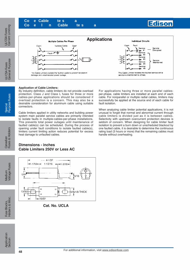
48
Co e Cable te s aCo e l n Cable te s a
For additional information, visit www.edisonfuse.com
Application of Cable Limiters:By industry definition, cable limiters do not provide overloadprotection. Class J and Class L fuses for three or morecables-per-phase applications should be considered if overload protection is a concern. This may also be a desirable consideration for aluminum cable using suitableconnectors.
Cable limiters applied in utility networks and building powersystem main parallel service cables are primarily intendedto isolate faults in multiple-cables-per-phase installations.This prevents total power outages until maintenance offaulted cable(s) can be scheduled. During the process ofopening under fault conditions to isolate faulted cable(s),limiters current limiting action reduces potential for excessheat damage to unfaulted cables.
Dimensions - inchesCable Limiters 250V or Less AC
For applications having three or more parallel cables-per-phase, cable limiters are installed at each end of eachcable. For nonparallel or multiple radial cables, limiters maysuccessfully be applied at the source end of each cable forfault isolation.
When analyzing cable limiter potential applications, it is notunusual to forget that normal and abnormal current throughcable limiters is divided just as it is between cables.Selectivity with upstream overcurrent protection devices isseldom of concern. When designing for cable limiter faultisolation to prevent a burn down or unscheduled blackout byone faulted cable, it is desirable to determine the continuousrating load (3 hours or more) that the remaining cables musthandle without overheating.
Cat. No. UCLA
Med
ium
Volta
ge F
uses
UL/C
SA F
uses
Curr
ent L
imiti
ngUL
/CSA
Fus
esGe
nera
l Pur
pose
Spec
ial
Purp
ose
Fuse
sCa
nadi
anFu
ses
& Ho
lder
sAp
plic
atio
nSe
ctio
nFu
se B
lock
s,Ho
lder
s &
Mis
c.

Circuit Protection
49For additional information, visit www.edisonfuse.com
Cable Limiters 600V or Less AC
Dimensions are shown in inches.*
Tube-Offset Blade (TO)**
CopperCatalog CableNumber Size A B C D E F GUCL25TO 250 MCM 1-7/8 1-7/16 3/4 19/32 31/32 1-1/8UCL35TO 350 MCM 2 3-5/8 3-3/8 1-5/8 7/8 45/64 1-1/16 1/4UCL50TO 500 MCM 2-7/8 1-7/8 1-1/16 53/64 1-3/16 1-5/8UCL75TO 750 MCM 3-1/2 3-3/4 3-1/2 2-1/2 1-5/16 1-1/16 1-1/2 2
Center Blade-Offset Blade (BO)**
CopperCatalog CableNumber Size A B C D E F GUCL25BO 250 MCM 1-7/16 1-1/8 1-1/8 31/32UCL35BO 350 MCM 3-3/8 3-5/8 1-5/8 1-1/16 1/4UCL50BO 500 MCM 1-7/8 1-1/2 1-5/8 1-3/16UCL75BO 750 MCM 3-1/2 3-3/4 2-1/2 2 2 1-1/2
Tube-Tube (TT)
CopperCatalog CableNumber Size A B C D EUCL25TT 250 MCM 1-7/8 1-7/16 3/4 19/32UCL35TT 350 MCM 2 3-5/8 1-5/8 7/8 45/64UCL50TT 500 MCM 2-7/8 1-7/8 1-1/16 53/64UCL75TT 750 MCM 3-1/2 2-7/8 2-1/2 1-5/16 1-1/16
A B A
DE
C
*Limiter terminals are silver plated copper.**Dimensions of TT , OO , TB , etc., terminals are determined by matching appropriate dimensions shown.
Co e Cable te s aCo e l n Cable te s a
Medium
Voltage FusesUL/CSA FusesCurrent Lim
itingUL/CSA FusesGeneral Purpose
SpecialPurpose Fuses
CanadianFuses & Holders
ApplicationSection
Fuse Blocks,Holders & M
isc.

50
Co e Cable te s aCo e l n Cable te s a
For additional information, visit www.edisonfuse.com
Average Time-Current Curve
Cat. No. UCL-(XXXX)-600Vac
Med
ium
Volta
ge F
uses
UL/C
SA F
uses
Curr
ent L
imiti
ngUL
/CSA
Fus
esGe
nera
l Pur
pose
Spec
ial
Purp
ose
Fuse
sCa
nadi
anFu
ses
& Ho
lder
sAp
plic
atio
nSe
ctio
nFu
se B
lock
s,Ho
lder
s &
Mis
c.
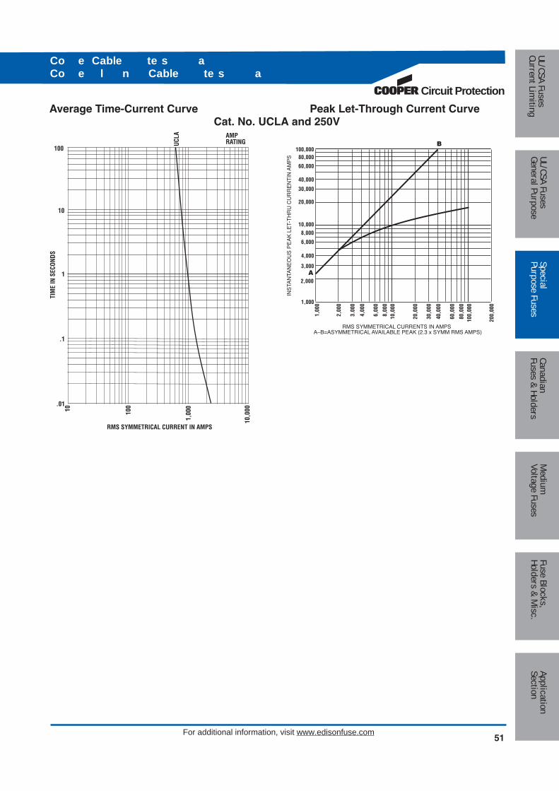
Circuit Protection
51For additional information, visit www.edisonfuse.com
AMPRATING
RMS SYMMETRICAL CURRENT IN AMPS
1,00
0
10010
10,0
00
UCLA
10
100
TIM
E IN
SEC
ONDS
1
.1
.01
100,00080,000
60,000
40,000
30,000
20,000
10,0008,000
6,000
4,000
3,000
2,000
1,000
1,00
0
2,00
0
3.00
0
4,00
0
6,00
0
8,00
010
,000
20,0
00
30,0
00
40,0
00
60,0
00
80,0
0010
0,00
0
200,
000
INS
TAN
TAN
EO
US
PE
AK
LE
T-T
HR
U C
UR
RE
NT
IN A
MP
S
RMS SYMMETRICAL CURRENTS IN AMPSA–B=ASYMMETRICAL AVAILABLE PEAK (2.3 x SYMM RMS AMPS)
B
A
Average Time-Current Curve Peak Let-Through Current CurveCat. No. UCLA and 250V
Co e Cable te s aCo e l n Cable te s a
Medium
Voltage FusesUL/CSA FusesCurrent Lim
itingUL/CSA FusesGeneral Purpose
SpecialPurpose Fuses
CanadianFuses & Holders
ApplicationSection
Fuse Blocks,Holders & M
isc.

52
a Ca a to ses
For additional information, visit www.edisonfuse.com
Cat. No. CCLB(Amps)600Vac or LessAC Interrupting Rating: 200kAWith open fuse indicatorUL Recognized (80 to 150A) E56412, JFHR2Non-Time Delay
Amp RatingsCCLB
80 150100 200125 250
Characteristics:• Stud mount with tapped terminals• Isolates faulted capacitor• Size amp rating 150% to 175% of capacitor rated amps• Maximum quality assurance
Dimensions - inches
Cat. No. CCLW(Amps)600Vac or LessAC Interrupting Rating: 200kAWithout open fuse indicatorUL Recognized 80-150A, (E56412, JFHR2)Non-Time Delay
Amp RatingsCCLW
50 15080 —100 —
Characteristics:• Stud mount and pressure plate terminals• Isolates faulted capacitor• Size amp rating 150% to 175% of capacitor rated amps• Maximum quality assurance
Dimensions - inches
2"
2-9/32"
3-13/16"
3/16"
1-1/32"
13/16"
BLOWN POSITIONINDICATOR
1" 1-1/2"
1/2"-13 THREADS11/16" DEEP
3/8"-16 THREADS3/4" DEEP
1/2"
3-17/32"
1.0"
HEX TERMINAL TAPPED1/2"-13 x 11/16" DEEP
1/2"
Med
ium
Volta
ge F
uses
UL/C
SA F
uses
Curr
ent L
imiti
ngUL
/CSA
Fus
esGe
nera
l Pur
pose
Spec
ial
Purp
ose
Fuse
sCa
nadi
anFu
ses
& Ho
lder
sAp
plic
atio
nSe
ctio
nFu
se B
lock
s,Ho
lder
s &
Mis
c.

Circuit Protection
53For additional information, visit www.edisonfuse.com
Average Time-Current Curve
Cat. No. CCLB or CCLW (Amp)
10,0
008,
000
6,00
0
4,00
03,
000
2,00
0
1,00
080
0
600
400
300
200
100806040302010
300
200
1008060
4030
20
1086
43
2
1.8.6
.4
.3
.2
.1.08.06
.04
.03
.02
.01
TIM
E IN
SE
CO
ND
S
RMS SYMMETRICAL CURRENT IN AMPS
25 75
AMPRATING10
015
0
200
50
a Ca a to ses
Medium
Voltage FusesUL/CSA FusesCurrent Lim
itingUL/CSA FusesGeneral Purpose
SpecialPurpose Fuses
CanadianFuses & Holders
ApplicationSection
Fuse Blocks,Holders & M
isc.

54
ft t atte C a e ses
For additional information, visit www.edisonfuse.com
Catalog Number ACK (15 - 400A), ACL (30 - 100A) and ALS (100 - 500A)
Applications:Popular for protection of DC circuits in fork lift trucks and battery chargers.
Catalog Dimensions (Inches)Number Type Volts Amps A B C
15, 20, 25, 30 2.500 0.250 0.563130Vdc 35, 40, 50, 60 3.000 0.344 0.813
ACK Time-Delay 70, 75, 80, 100 3.500 0.313 1.06372Vdc 120, 140, 150, 175, 200 3.635 0.313 1.06348Vdc 225, 250, 300, 400 3.875 0.313 1.063
ACL Time-Delay 72Vdc 30, 35, 40, 50, 60 2.500 0.250 0.56380, 100
Non-Time 130Vdc 100, 120, 140, 150, 175ALS Delay
36Vdc200, 225, 250, 300 3.750 0.375 1.063350, 400, 450, 500
C (Dia.)
B
A
Dimensions - inches
Med
ium
Volta
ge F
uses
UL/C
SA F
uses
Curr
ent L
imiti
ngUL
/CSA
Fus
esGe
nera
l Pur
pose
Spec
ial
Purp
ose
Fuse
sCa
nadi
anFu
ses
& Ho
lder
sAp
plic
atio
nSe
ctio
nFu
se B
lock
s,Ho
lder
s &
Mis
c.
CROSS REFERENCENEW OLDEDISON EDISON GOULD LITTELFUSEACK ECK — CCKACL ECL — CCLALS AOK — —

Circuit Protection
55For additional information, visit www.edisonfuse.com
Amp RatingsANL 125Vac
35 130 35040 150 32550 175 35060 200 40080 225 500100 250 —
Catalog Number ANL (35 - 500A)125Vac or Less
ANL Specifications:Non-Time-Delay
Voltage Rating: 80Vdc, 125Vac
Interrupting Rating: 6kA
Recommended Fuse Block: 4164
Characteristics:• Isolates faults in equipment systems such as lift trucks
and other battery operated systems.• Silver-plated copper links.• Link element visible through mica window.
Average Time-Current Curve
10,0
0010 100
1000
CURRENT IN AMPS
100
10
1
.1
.01
TIM
E IN
SE
CO
ND
S
AMPRATING5035 80 10
013
015
020
022
527
532
535
040
050
0
0.34"(8.7mm)
0.88"(22.2mm)
0.88"(22.2mm)
0.34"(8.7mm)
3.19"(81.0mm)
2.44"(61.9mm)
o olta e te on T e ela
15/16"
0.483"
1"
3-13/32"
1.563"
516-24
Fuse Block 4164Holes drilled 0.217” diameter with 0.438” counterbore with5/16-24 stud.
Dimensions - inches
Medium
Voltage FusesUL/CSA FusesCurrent Lim
itingUL/CSA FusesGeneral Purpose
SpecialPurpose Fuses
CanadianFuses & Holders
ApplicationSection
Fuse Blocks,Holders & M
isc.
CROSS REFERENCENEW OLDEDISON EDISON GOULD LITTELFUSEANL ENLE CNL CNL

56
tee ast t n
For additional information, visit www.edisonfuse.com
Amp RatingsANN 125Vac
35 125 35040 150 40050 175 50060 200 60080 275 80090 300 —100 325 —
Catalog Number ANN (35 - 800A)125Vac or Less
ANN Specifications:Very Fast-Acting
Voltage Rating: 80Vdc, 125Vac
Interrupting Rating: 2.5kA
Recommended Fuse Block: 4164
Characteristics:• Very fast-acting (high speed of response to short-circuit
currents.• Link element visible through mica window.• UL Recognized 35-400A (Guide #JFHR2, File #E56412)
Average Time-Current Curve
10,0
0010 100
1000
CURRENT IN AMPS
100
10
1
.1
.01
TIM
E IN
SE
CO
ND
S
AMPRATING35 50 60 80
100
125
150
200
300
400
500
250
600
800
0.34"(8.7mm)
0.88"(22.2mm)
0.88"(22.2mm)
0.34"(8.7mm)
3.19"(81.0mm)
2.44"(61.9mm)
15/16"
0.483"
1"
3-13/32"
1.563"
516-24
Fuse Block 4164Holes drilled 0.217” diameter with 0.438” counterbore with5/16-24 stud.
Dimensions - inches
Med
ium
Volta
ge F
uses
UL/C
SA F
uses
Curr
ent L
imiti
ngUL
/CSA
Fus
esGe
nera
l Pur
pose
Spec
ial
Purp
ose
Fuse
sCa
nadi
anFu
ses
& Ho
lder
sAp
plic
atio
nSe
ctio
nFu
se B
lock
s,Ho
lder
s &
Mis
c.
CROSS REFERENCENEW OLDEDISON EDISON GOULD LITTELFUSEANN ENNE CNN CNN

Circuit Protection
57For additional information, visit www.edisonfuse.com
ee ses
Catalog Amp UL Component RecognitionVoltages Number Ratings Vac AC AIR Vdc DC AIR
130V E13S (Amp) 1000 – 3000 130 200,000 130150V E15SF(Amp) 5 – 60 150 200,000 150
E15S(Amp) 70 – 1000E25SFX(Amp) 5 – 30 250 10,000
250V E25S(Amp) 35 – 800 250 200,000 250 10,000E25S(Amp) 1000 – 2500 — —E50SF(Amp) 5 – 30 500 10,000
500V E50S(Amp) 35 – 1600 500 200,000 500 100,000E50S(Amp) 900-1200 — —
0 - 20 10,000600V E60C(Amp) 25 - 600 600 100,000
700 – 1000600V E60SF(Amp) 5 – 30 600 200,000
E60S(Amp) 35 – 600E70SF(Amp) 5 – 30 700 10,000
700V E70S(Amp) 35 – 800 700 200,000 700 10,000E70S(Amp) 1000 – 1200 — —E100SF(Amp) 20 – 30 800
1000V E100S(Amp) 40 – 500 1000 200,000 800E100S(Amp) 600 – 800 700
Standard Ratings
Current Rating
The maximum current carrying capability is at least equal tothe current rating, provided that the ambient temperature isless than 30°C, conductor sizes are at least 1mm2 per amp,and there is natural convection cooling.
For ambient temperatures higher than 30°C, a derating of0.5% per °C is recommended. In situations where the airtemperature surrounding the fuse is higher than the ambient temperature, i.e. inside a converter cubicle, thederating should be based on the air temperature surrounding the fuses.
In many installations, power semiconductors are forcecooled in an air stream. Fuses can be mounted in this airstream and their maximum current carrying capability canthen be increased. This increase is up to approximately20% in an air velocity of 5m/s but higher velocities do notproduce any substantial increase in rating.
Technical Data
In many cases, the data in this catalog section whichincludes available ratings, dimensions, time current characteristics and I2t let-through, will enable a suitablechoice of fuse to be made. The following notes are a guideto assist fuse selection.
Voltage Rating
The test voltage is equal to the rated voltage. The DCvoltage ratings are tested with a time constant of 10ms. Forlonger time constants the following typical derating factorsapply:
Time constant ms 25 40 60Voltage derating factor 0.85 0.7 0.6
Medium
Voltage FusesUL/CSA FusesCurrent Lim
itingUL/CSA FusesGeneral Purpose
SpecialPurpose Fuses
CanadianFuses & Holders
ApplicationSection
Fuse Blocks,Holders & M
isc.

58
ee ses
For additional information, visit www.edisonfuse.com
Breaking Capacity
In general, high speed fuses perform well at very high faultcurrents and many products have been successfully testedup to 200kA rms symmetrical. The fuses are essentially forshort-circuit protection and therefore in general, onlyrequired to clear faults for melting times less than 30 seconds.
Peak Let-Through Current Curves
Short-circuit coordination of power semiconductors isassessed with the use of I2t values. Traditional supplementary peak let-through current curves are alsoshown in the catalog.
Arc-Voltage Characteristics
Applications using modern power semiconductors are notnormally sensitive to the peak arc voltages produced byEdison high speed fuses.
Typical values of arc voltages in relation to the rated fusevoltage, Un, are:
System Voltage Arc Voltage of FuseUn 2.0 Un0.5 Un 1.25 Un0.2 Un 0.7 Un
Power Dissipation
The values of watts loss given are related to full rated current with the correct sizes of conductors and naturalcooling.
Time Current Characteristics
Individual time current characteristics are subject to a ±10%tolerance on current and are based on symmetricalsinusoidal 60Hz currents. High speed fuses are designedto clear fault currents associated with pre-arcing times of 30 seconds or less. Dashed lines on time-current characteristic curves represent overload conditions which,should always be avoided.
Permitted Overloads
In many applications, surges occur during the normal dutyof equipment and under such permitted overloads, the fusemust not open.
For permitted overloads lasting longer than a few minutes,the fuse current rating should be selected based on theoverload current. The current rating of the fuse shouldexceed the overload current.
For infrequent normal overloads, fuse selection can bemade on the basis of an overload curve of not more than75% of the published time current characteristic.
For highly repetitive overloads, such as in a steel mill thyristor drive, fuse selection should be made on the basisof an overload curve of not more than 60% of the publishedtime current characteristic.
I2t Characteristics
The melting I2t of fuses is independent of voltage andreduces to a minimum value for times less than about 1ms.For longer times, reference should be made to the time current characteristics.
The total I2t values for operating times less than one half-cycle are shown in the data sheets and relate to a fault current of at least 20x rated current, In, with a power factorof 15%.
The total I2t values reduce considerably at voltages belowthe rated voltage since the arc interruption is easier.
Example: a 500V Edison high speed fuse used on a 250Vsystem would produce an arc voltage of approximately 625volts.
Med
ium
Volta
ge F
uses
UL/C
SA F
uses
Curr
ent L
imiti
ngUL
/CSA
Fus
esGe
nera
l Pur
pose
Spec
ial
Purp
ose
Fuse
sCa
nadi
anFu
ses
& Ho
lder
sAp
plic
atio
nSe
ctio
nFu
se B
lock
s,Ho
lder
s &
Mis
c.
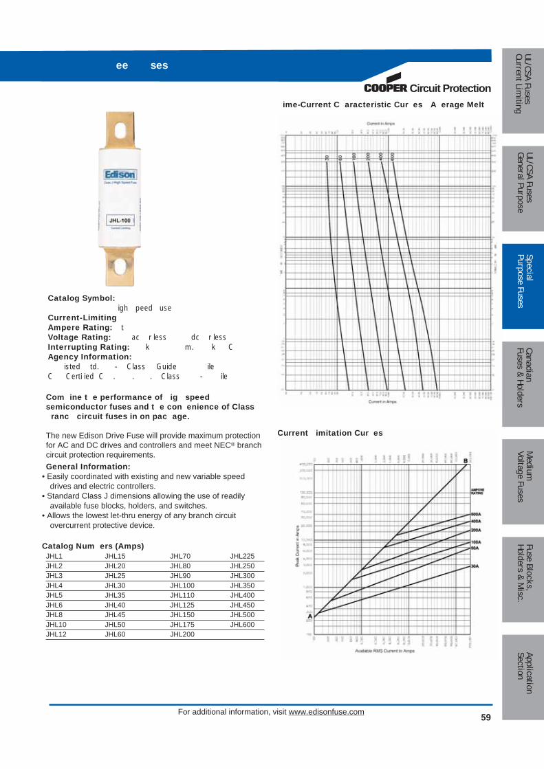
Circuit Protection
59For additional information, visit www.edisonfuse.com
ee ses
Medium
Voltage FusesUL/CSA FusesCurrent Lim
itingUL/CSA FusesGeneral Purpose
SpecialPurpose Fuses
CanadianFuses & Holders
ApplicationSection
Fuse Blocks,Holders & M
isc.
Catalog Symbol: igh peed use
Current-LimitingAmpere Rating: t Voltage Rating: ac r less dc r lessInterrupting Rating: k m. k CAgency Information:
isted td. - Class Guide ile C Certi ied C . . . Class - ile
Catalog Num ers (Amps)JHL1 JHL15 JHL70 JHL225JHL2 JHL20 JHL80 JHL250JHL3 JHL25 JHL90 JHL300JHL4 JHL30 JHL100 JHL350JHL5 JHL35 JHL110 JHL400JHL6 JHL40 JHL125 JHL450JHL8 JHL45 JHL150 JHL500JHL10 JHL50 JHL175 JHL600JHL12 JHL60 JHL200
Com ine t e performance of ig speed semiconductor fuses and t e con enience of Class
ranc circuit fuses in on pac age.
The new Edison Drive Fuse will provide maximum protectionfor AC and DC drives and controllers and meet NEC® branchcircuit protection requirements.General Information:
• Easily coordinated with existing and new variable speed drives and electric controllers.
• Standard Class J dimensions allowing the use of readilyavailable fuse blocks, holders, and switches.
• Allows the lowest let-thru energy of any branch circuit overcurrent protective device.
ime-Current C aracteristic Cur es A erage Melt
Current imitation Cur es

60 For additional information, visit www.edisonfuse.com
ee ses
Med
ium
Volta
ge F
uses
UL/C
SA F
uses
Curr
ent L
imiti
ngUL
/CSA
Fus
esGe
nera
l Pur
pose
Spec
ial
Purp
ose
Fuse
sCa
nadi
anFu
ses
& Ho
lder
sAp
plic
atio
nSe
ctio
nFu
se B
lock
s,Ho
lder
s &
Mis
c.
Catalog Number E13S(Amp) 130Vac/130Vdc
E1 S(Amp) Dimensions - inchesCatalog Numbers Figure B C Threat DepthE1351000HP-2000 1 2.0 1.0 Tapped 3/8 - 24 x 1/2E13S2500-3000 1 3.0 1.5 Tapped 1/2 - 20 x 1/2
E1 S(Amp) Electrical CharacteristicsCatalog Numbers Rated Current RMS Amps Melting I2t Clearing I2t 1 0V Watts Loss Rated Current
E13S1000HP 1000 170,000 460,000 60E13S1200 1200 270,000 730,000 70E13S1500 1500 520,000 1,400,000 78E13S2000 2000 860,000 2,400,000 108E13S2500 2500 1,500,000 4,100,000 130E13S3000 3000 2,100,000 5,700,000 150
1.875 CB
NOTE: To cross reference 130V high speed fuses below 1000A, refer to upgraded EdisonE15S(Amp) — 150V fuses.
A
B
AM
PR
ATIN
G
1000,000
100,000
10,000
1000 1 10 100
200
RMS SYMMETRICAL CURRENTS IN AMPSA–B=ASYMMETRICAL AVAILABLE PEAK (2.3 X SYMM RMS AMPS)
INS
TAN
TAN
EO
US
PE
AK
LE
T-TH
RO
UG
H C
UR
RE
NT
IN A
MP
S
15001200
1000
200025003000
1000
A
AMP RATING
CURRENT IN AMPS
10,0
00
1,00
0
100
100,
000
1200
A15
00A
2000
A25
00A
3000
A
10
100
TIM
E IN
SE
CO
ND
S
1
.1
.01
Peak Let-Through Current Curves
E13S1000 — 3000, 130V
Minimum Melting Curves
E13S1000 — 3000, 130V
UL Recognized
Figure 1: 1000 – 3000A Range
Dimensions - inches

Circuit Protection
61For additional information, visit www.edisonfuse.com
ee ses
Catalog Number E15SF5 – 60
E15SF(Amp) Dimensions - inches (mm)Catalog Numbers Figure A B C
E15SF5 – 30 1 1.500 (38.1) 0.375 (9.5) 0.406 (10.3)E15SF35 – 60 1 2.000 (50.8) 0.625 (15.9) 0.812 (20.6)
E15S(Amp) Dimensions - inches (mm)Catalog Numbers Figure A B C D E F GE15S70 – 400 2 2.656 (67.5) 2.062 (52.4) 1.156 (29.4) 1.000 (25.4) 0.125 (3.2) 0.750 (19.1) 0.312 (7.9) 0.438 (11.1)
E15S500 – 1000 3 3.500 (88.9) 2.438 (61.9) 1.250 (31.8) 1.500 (38.1) 0.250 (6.4) 1.000 (25.4) 0.406 (10.3) 0.406 (10.3)
C
B
AUL Recognized
Figure 1: 5 – 60A Range
G
F
H
C
B
A
E
D
Figure 2: 70 – 400A Range
E
D
C
B
A
GF
H
Figure 3: 500 – 1000A Range
Dimensions - in (mm)
Catalog Number E15S70 – 1000
Medium
Voltage FusesUL/CSA FusesCurrent Lim
itingUL/CSA FusesGeneral Purpose
SpecialPurpose Fuses
CanadianFuses & Holders
ApplicationSection
Fuse Blocks,Holders & M
isc.

ee ses
For additional information, visit www.edisonfuse.com62
Med
ium
Volta
ge F
uses
UL/C
SA F
uses
Curr
ent L
imiti
ngUL
/CSA
Fus
esGe
nera
l Pur
pose
Spec
ial
Purp
ose
Fuse
sCa
nadi
anFu
ses
& Ho
lder
sAp
plic
atio
nSe
ctio
nFu
se B
lock
s,Ho
lder
s &
Mis
c.
Catalog Number E15S(Amp) 150Vac/150Vdc*
Catalog Number E15SF(Amp) 150Vac/130Vdc
E15SF(Amp) 150Vac 1 0Vdc Electrical CharacteristicsCatalog Number Rated Current RMS Amps Melting I2t Clearing I2t 150V Watts Loss Rated Current
E15SF5 5 1.6 8 1.1E15SF10 10 3.6 16 2.7E15SF15 15 14.5 55 3.3E15SF20 20 33.0 130 3.8E15SF25 25 58.0 220 4.5E15SF30 30 100.0 400 4.9E15SF35 35 75.0 800 4.5E15SF40 40 102.0 1000 5.1E15SF45 45 133.0 1300 6.0E15SF50 50 168.0 1600 7.3E15SF60 60 250.0 2400 8.0
E15S(Amp) 150Vac 150Vdc Electrical CharacteristicsCatalog Number Rated Current RMS Amps Melting I2t Clearing I2t 150V Watts Loss Rated Current
E15S70 70 467 4000 6.9E15S80 80 670 6000 7.7E15S100 100 1200 12000 9.0E15S125 125 1870 18000 11.2E15S150 150 2700 26000 13.5E15S200 200 4780 45000 17.6E15S250 250 7470 70000 22.5E15S300 300 10760 100000 27.0E15S350 350 15700 140000 30.6E15S400 400 20340 180000 35.2E15S500 500 39000 120000 35.0E15S600 600 46000 140000 47.0E15S700 700 75000 220000 49.0E15S800 800 92000 280000 58.0
E15S1000 1000 170000 510000 60.0
Interrupting Rating 200kA RMS Symmetrical.*150Vdc rating applies to 70 – 800A only.

Circuit Protection
63For additional information, visit www.edisonfuse.com
ee ses
AMP RATING
CURRENT IN AMPS
100101
1,00
0
5A 10A
15A
20A
25A
30A
35A
40A
45A
50A
60A
10
100
TIM
E IN
SE
CO
ND
S
1
.1
.01
AMP RATING
CURRENT IN AMPS
1,00
0
10010
10,0
00
1000
A80
0A70
0A60
0A40
0A50
0A35
0A30
0A25
0A20
0A15
0A12
5A10
0A80
A70
A
10
100
TIM
E IN
SE
CO
ND
S
1
.1
.01
A
B
AM
PR
ATIN
G
10,000
1,000
100
10
10 100
1,00
0
2,00
0
RMS SYMMETRICAL CURRENTS IN AMPSA–B=ASYMMETRICAL AVAILABLE PEAK (2.3 X SYMM RMS AMPS)
INS
TAN
TAN
EO
US
PE
AK
LE
T-TH
RO
UG
H C
UR
RE
NT
IN A
MP
S
30
4045
6050
35
25201512105
A
B
AM
PR
ATIN
G
1,000,000
100,000
10,000
1,000
1,00
0
10,0
00
100,
000
RMS SYMMETRICAL CURRENTS IN AMPSA–B=ASYMMETRICAL AVAILABLE PEAK (2.3 X SYMM RMS AMPS)
INS
TAN
TAN
EO
US
PE
AK
LE
T-TH
RO
UG
H C
UR
RE
NT
IN A
MP
S
5006007008001000
Time-Current, Minimum Melting Curves
E15SF(Amp) High Speed Fuse5 – 60A, 150V
E15S(Amp) High Speed Fuse70 – 1000A, 150V
Peak Let-Through Current Curves
E15SF(Amp) High Speed Fuse5 – 60A, 150V
E15S(Amp) High Speed Fuse70 – 1000A, 150V
Medium
Voltage FusesUL/CSA FusesCurrent Lim
itingUL/CSA FusesGeneral Purpose
SpecialPurpose Fuses
CanadianFuses & Holders
ApplicationSection
Fuse Blocks,Holders & M
isc.

64
ee ses
For additional information, visit www.edisonfuse.com
Med
ium
Volta
ge F
uses
UL/C
SA F
uses
Curr
ent L
imiti
ngUL
/CSA
Fus
esGe
nera
l Pur
pose
Spec
ial
Purp
ose
Fuse
sCa
nadi
anFu
ses
& Ho
lder
sAp
plic
atio
nSe
ctio
nFu
se B
lock
s,Ho
lder
s &
Mis
c.
Catalog Number E25S(Amp) 35 – 2500A
Catalog Number E25SFX(Amp) 5 – 30A, 250Vac/250Vdc
E25S(Amp) Dimensions - inches (mm)Catalog Numbers Figure A B C D E F G
E25S35 – 60 1 3.19 (81.0) 0.81 (20.6) 1.59 (40.4) 2.59 (65.8) 2.25 (57.2) 0.34 (8.6) 0.63 (16.0) 0.13 (3.3) 0.52 (13.2)E25S70 – 200 1 3.13 (79.5) 1.22 (31.0) 1.59 (40.4) 2.44 (62.0) 2.19 (55.6) 0.34 (8.6) 1.00 (25.4) 0.19 (4.8) 0.47 (11.9)
E25S225 – 600 1 3.84 (97.5) 1.50 (38.1) 1.59 (40.4) 2.94 (74.7) 2.25 (57.2) 0.41 (10.4) 1.00 (25.4) 0.25 (6.4) 0.75 (19.1)E25S700 – 800 1 3.84 (97.5) 2.00 (50.8) 1.59 (40.4) 3.03 (77.0) 2.28 (57.9) 0.41 (10.4) 1.50 (38.1) 0.25 (6.4) 0.78 (19.8)
E25S1000 – 1200 2 2.59 (65.8) 3.00 (76.2) 1.50 (38.1) — — — — — —E25S1500 – 2500 3 2.59 (65.8) 3.50 (88.9) 1.50 (38.1) 1.50 (38.1) — — — — —
15.5(0.610")
50.8(2.000")
14.3(0.563")
J
CEDA
G
F
H
B
Figure 1: 35 – 800A Range
B C
A
Figure 2: 1000 – 1200A Range
B C
A
D
Figure 3: 1500 – 2500A Range
Thread Depth
Tapped 8 -24 x 1 2
Dimensions - inches (mm)

Circuit Protection
65For additional information, visit www.edisonfuse.com
ee ses
E25S(Amp) 250Vac 250Vdc Electrical CharacteristicsCatalog Numbers Rated Current RMS Amps Melting I2t Clearing I2t 250V Watts Loss Rated Current
E25SFX5 5 1.6 15 1.3E25SFX10 10 3.6 24 3.4E25SFX15 15 14.5 83 3.8E25SFX20 20 33.0 190 4.6E25SFX25 25 58.0 290 5.3E25SFX30 30 100.0 520 5.6E25S35 35 50.0 230 4.2E25S40 40 60.0 310 5.2E25S45 45 80.0 390 5.7E25S50 50 100 520 6.0E25S60 60 140 740 8.1E25S70 70 330 1400 7.2E25S80 80 430 1850 8.1E25S90 90 570 2450 9.0E25S100 100 740 3150 10.0E25S125 125 1130 4850 12.5E25S150 150 1620 6950 15.7E25S175 175 2170 9300 18.5E25S200 200 2790 12000 22.0E25S225 225 3210 14700 24.0E25S250 250 3960 18100 27.0E25S275 275 4720 21600 31.0E25S300 300 6000 27300 32.0E25S350 350 10600 48600 39.0E25S400 400 14500 66100 44.0E25S450 450 22100 101000 49.0E25S500 500 28000 128000 54.0E25S600 600 41100 188000 62.0E25S700 700 48800 190000 72.0E25S800 800 59000 230000 84.0E25S1000 1000 44000 360000 100.0E25S1200 1200 92000 750000 103.0E25S1500 1500 120000 880000 140.0E25S1600 1600 160000 1200000 140.0E25S2000 2000 320000 2300000 151.0E25S2500 2500 670000 4700000 163.0
Catalog Number E25S(Amp) 250Vac/250Vdc*
UL Recognized*
Interrupting Rating 200kA RMS Symmetrical.*250Vdc rating and UL Recognition on 5 – 800A only.
Medium
Voltage FusesUL/CSA FusesCurrent Lim
itingUL/CSA FusesGeneral Purpose
SpecialPurpose Fuses
CanadianFuses & Holders
ApplicationSection
Fuse Blocks,Holders & M
isc.

66
ee ses
For additional information, visit www.edisonfuse.com
Med
ium
Volta
ge F
uses
UL/C
SA F
uses
Curr
ent L
imiti
ngUL
/CSA
Fus
esGe
nera
l Pur
pose
Spec
ial
Purp
ose
Fuse
sCa
nadi
anFu
ses
& Ho
lder
sAp
plic
atio
nSe
ctio
nFu
se B
lock
s,Ho
lder
s &
Mis
c.
AMP RATING
CURRENT IN AMPS
100104
1,00
0
3,00
0
30A
10
100
25A
20A
15A
10A
5A
TIM
E IN
SE
CO
ND
S
1
.1
.01
AMP RATING
CURRENT IN AMPS1,
000
10010
10,0
00
35A
100
1,000
45A
60A
70A
100A
150A
200A
350A
400A
500A
600A
800A
TIM
E IN
SE
CO
ND
S
10
1
.1
A A
A
B
AM
PR
ATIN
G
100,000
10,000
1,000
100
100
1,00
0
10,0
00
20,0
00
RMS SYMMETRICAL CURRENTS IN AMPSA–B=ASYMMETRICAL AVAILABLE PEAK (2.3 X SYMM RMS AMPS)
INS
TAN
TAN
EO
US
PE
AK
LE
T-TH
RO
UG
H C
UR
RE
NT
IN A
MP
S
600
150
400300
200
10080605035
A
B
AM
PR
ATIN
G
100,000
10,000
1,000
100
100
1,00
0
10,0
00
20,0
00
RMS SYMMETRICAL CURRENTS IN AMPSA–B=ASYMMETRICAL AVAILABLE PEAK (2.3 X SYMM RMS AMPS)
INS
TAN
TAN
EO
US
PE
AK
LE
T-TH
RO
UG
H C
UR
RE
NT
IN A
MP
S
70
800600400300200150100
604535
Time-Current, Minimum Melting Curves
E25SFX(Amp) High Speed Fuse5 – 30A, 250V
E25S(Amp) High Speed Fuse35 – 800A, 250V
Peak Let-Through Current Curves
E25SFX(Amp) High Speed Fuse5 – 30A, 250V
E25S(Amp) High Speed Fuse35 – 800A, 250V
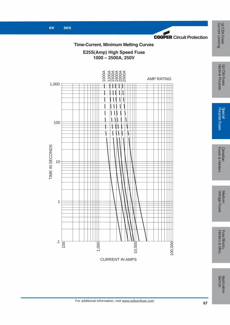
Circuit Protection
67For additional information, visit www.edisonfuse.com
ee ses
AMP RATING
CURRENT IN AMPS
100,
000
10,0
00
1,00
0
100
100
1,000
1000
A12
00A
1500
A16
00A
2000
A25
00A
TIM
E IN
SE
CO
ND
S
10
1
.1
Time-Current, Minimum Melting Curves
E25S(Amp) High Speed Fuse1000 – 2500A, 250V
Medium
Voltage FusesUL/CSA FusesCurrent Lim
itingUL/CSA FusesGeneral Purpose
SpecialPurpose Fuses
CanadianFuses & Holders
ApplicationSection
Fuse Blocks,Holders & M
isc.
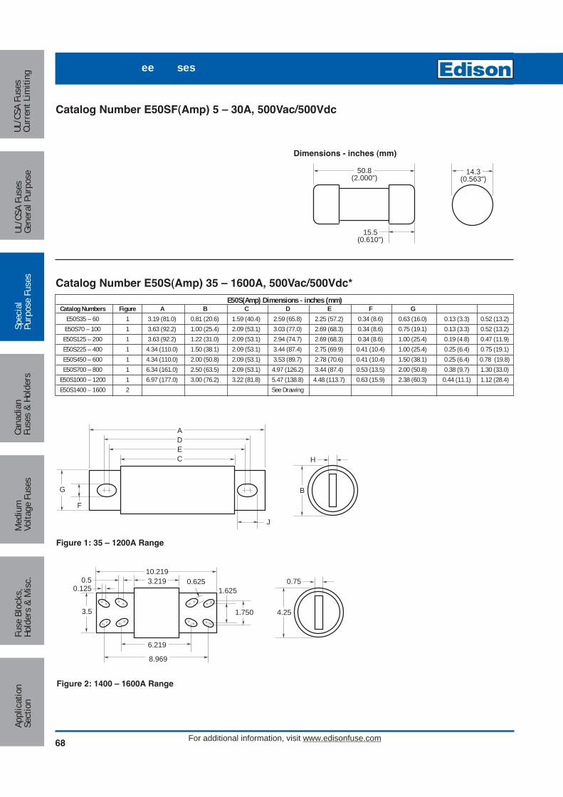
68
ee ses
For additional information, visit www.edisonfuse.com
Med
ium
Volta
ge F
uses
UL/C
SA F
uses
Curr
ent L
imiti
ngUL
/CSA
Fus
esGe
nera
l Pur
pose
Spec
ial
Purp
ose
Fuse
sCa
nadi
anFu
ses
& Ho
lder
sAp
plic
atio
nSe
ctio
nFu
se B
lock
s,Ho
lder
s &
Mis
c.
Catalog Number E50SF(Amp) 5 – 30A, 500Vac/500Vdc
Catalog Number E50S(Amp) 35 – 1600A, 500Vac/500Vdc*E50S(Amp) Dimensions - inches (mm)
Catalog Numbers Figure A B C D E F GE50S35 – 60 1 3.19 (81.0) 0.81 (20.6) 1.59 (40.4) 2.59 (65.8) 2.25 (57.2) 0.34 (8.6) 0.63 (16.0) 0.13 (3.3) 0.52 (13.2)E50S70 – 100 1 3.63 (92.2) 1.00 (25.4) 2.09 (53.1) 3.03 (77.0) 2.69 (68.3) 0.34 (8.6) 0.75 (19.1) 0.13 (3.3) 0.52 (13.2)
E50S125 – 200 1 3.63 (92.2) 1.22 (31.0) 2.09 (53.1) 2.94 (74.7) 2.69 (68.3) 0.34 (8.6) 1.00 (25.4) 0.19 (4.8) 0.47 (11.9)E50S225 – 400 1 4.34 (110.0) 1.50 (38.1) 2.09 (53.1) 3.44 (87.4) 2.75 (69.9) 0.41 (10.4) 1.00 (25.4) 0.25 (6.4) 0.75 (19.1)E50S450 – 600 1 4.34 (110.0) 2.00 (50.8) 2.09 (53.1) 3.53 (89.7) 2.78 (70.6) 0.41 (10.4) 1.50 (38.1) 0.25 (6.4) 0.78 (19.8)E50S700 – 800 1 6.34 (161.0) 2.50 (63.5) 2.09 (53.1) 4.97 (126.2) 3.44 (87.4) 0.53 (13.5) 2.00 (50.8) 0.38 (9.7) 1.30 (33.0)
E50S1000 – 1200 1 6.97 (177.0) 3.00 (76.2) 3.22 (81.8) 5.47 (138.8) 4.48 (113.7) 0.63 (15.9) 2.38 (60.3) 0.44 (11.1) 1.12 (28.4)E50S1400 – 1600 2 See Drawing
15.5(0.610")
50.8(2.000")
14.3(0.563")
J
CEDA
G
F
H
B
Figure 1: 35 – 1200A Range
0.75
4.25
3.2190.50.125
3.5
1.625
1.750
0.62510.219
6.219
8.969
Figure 2: 1400 – 1600A Range
Dimensions - inches (mm)

Circuit Protection
69For additional information, visit www.edisonfuse.com
ee ses
Catalog Number E50S(Amp) 500Vac/500Vdc*
E50S(Amp) 500Vac 500Vdc Electrical CharacteristicsCatalog Numbers Rated Current RMS Amps Melting I2t Clearing I2t 500V Watts Loss Rated Current
E50SF5 5 1.6 2.5 1.5E50SF10 10 3.6 6.0 4.0E50SF15 15 10.0 16 5.5E50SF20 20 26.0 40 6.0E50SF25 25 49.0 75 7.0E50SF30 30 58.0 90 9.0E50S35 35 130 920 5.5E50S40 40 180 1250 6.9E50S50 50 280 1930 8.0E50S60 60 410 2700 9.4E50S70 70 290 1860 12.7E50S80 80 430 2740 13.4E50S90 90 590 3800 15.6E50S100 100 730 4700 16.8E50S125 125 1100 5950 24.0E50S150 150 2000 10800 26.0E50S175 175 2800 15300 30.0E50S200 200 3900 21000 32.0E50S225 225 4600 23300 39.0E50S250 250 6300 32200 41.0E50S275 275 7900 40300 46.0E50S300 300 9800 49800 51.0E50S325 325 13700 63800 53.0E50S350 350 14500 72900 58.0E50S400 400 19200 96700 65.0E50S450 450 24700 127000 74.0E50S500 500 29200 149000 84.0E50S600 600 41300 206000 108.0E50S700 700 55000 298000 120.0E50S800 800 76200 409000 129.0E50S1000 1000 92000 450000 145.0E50S1200 1200 122000 600000 180.0E50S1400 1400 200000 100000 210.0E50S1600 1600 290000 1400000 230.0
UL Recognized
†
Interrupting Rating 200kA RMS Symmetrical.*500Vdc rating and UL Recognition on 5 – 800A only.†UL Recognition on 5 – 1200 amps only.
Medium
Voltage FusesUL/CSA FusesCurrent Lim
itingUL/CSA FusesGeneral Purpose
SpecialPurpose Fuses
CanadianFuses & Holders
ApplicationSection
Fuse Blocks,Holders & M
isc.
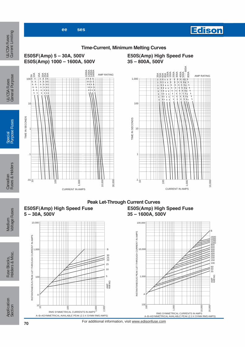
70
ee ses
For additional information, visit www.edisonfuse.com
Med
ium
Volta
ge F
uses
UL/C
SA F
uses
Curr
ent L
imiti
ngUL
/CSA
Fus
esGe
nera
l Pur
pose
Spec
ial
Purp
ose
Fuse
sCa
nadi
anFu
ses
& Ho
lder
sAp
plic
atio
nSe
ctio
nFu
se B
lock
s,Ho
lder
s &
Mis
c.
AMP RATING
CURRENT IN AMPS
1000
A12
00A
1,00
0
10010
10,0
00
30,0
00
1400
A16
00A
TIM
E IN
SE
CO
ND
S
1
.1
.01
10
100
5A 10A
15A
20A
25A
30A
AMP RATING
CURRENT IN AMPS1,
000
10010
10,0
00
800A
600A
100
1,000
500A
400A
300A
200A
150A
100A
80A
60A
50A
35A
TIM
E IN
SE
CO
ND
S10
1
.1
A
B
AM
PR
ATIN
G
10,000
1,000
100
10
10 100
1,00
0
2,00
0
RMS SYMMETRICAL CURRENTS IN AMPSA–B=ASYMMETRICAL AVAILABLE PEAK (2.3 X SYMM RMS AMPS)
INS
TAN
TAN
EO
US
PE
AK
LE
T-TH
RO
UG
H C
UR
RE
NT
IN A
MP
S
15
10
5
202530
A
B
AM
PR
ATIN
G
100,000
10,000
1,000
100
100
1,00
0
10,0
00
20,0
00
RMS SYMMETRICAL CURRENTS IN AMPSA–B=ASYMMETRICAL AVAILABLE PEAK (2.3 X SYMM RMS AMPS)
INS
TAN
TAN
EO
US
PE
AK
LE
T-TH
RO
UG
H C
UR
RE
NT
IN A
MP
S
800
150
400300
200
100605035
600500
250
1600140012001000
Time-Current, Minimum Melting Curves
E50S(Amp) High Speed Fuse35 – 800A, 500V
E50SF(Amp) 5 – 30A, 500VE50S(Amp) 1000 – 1600A, 500V
Peak Let-Through Current CurvesE50S(Amp) High Speed Fuse35 – 1600A, 500V
E50SF(Amp) High Speed Fuse5 – 30A, 500V

Circuit Protection
71For additional information, visit www.edisonfuse.com
ee ses
E60C(Amp) Dimensions - inchesCatalog Numbers Figure A B1 B2 B C D E F G
E60C4 – 30 1 2.875 2.500 — — 1.875 0.406 — 0.563 0.063 0.257E60C35 – 60 2 4.375 — 3.750 3.500 2.750 0.625 0.343 0.813 0.094 0.468E60C70 – 100 2 5.000 — 4.167 3.656 2.906 0.750 0.406 1.000 0.125 0.609E60C110 – 200 2 5.500 — 4.375 3.063 2.906 1.125 0.406 1.500 0.188 0.767E60C225 – 400 1 6.250 4.750 — — 3.000 1.625 — 2.000 0.250 0.563E60C450 – 800 1 6.250 4.750 — — 3.063 2.000 — 2.500 0.250 0.563E60C1000 1 7.250 4.750 — — 3.063 2.750 — 3.500 0.375 0.563
Catalog Number E60C(1 – 1000A) 600Vac or LessNOTE: Edison 600V rectifier fuses are for replacement purposes only. For new applications, refer to E70S(Amp) fuses.
Amp Ratings E60C(AMP) 600V4 12 40 90 200 4505 15 45 100 225 5006 20 50 110 250 6007 25 60 125 300 7008 30 70 150 350 800
10 35 80 175 400 1000
H
CB1A
D
G
F
Figure 1: 4 – 30A & 225 – 1000A Range
H
CB3B2A
D
E
G
F
Figure 2: 35 – 200A Range
Medium
Voltage FusesUL/CSA FusesCurrent Lim
itingUL/CSA FusesGeneral Purpose
SpecialPurpose Fuses
CanadianFuses & Holders
ApplicationSection
Fuse Blocks,Holders & M
isc.

72
ee ses
For additional information, visit www.edisonfuse.com
Med
ium
Volta
ge F
uses
UL/C
SA F
uses
Curr
ent L
imiti
ngUL
/CSA
Fus
esGe
nera
l Pur
pose
Spec
ial
Purp
ose
Fuse
sCa
nadi
anFu
ses
& Ho
lder
sAp
plic
atio
nSe
ctio
nFu
se B
lock
s,Ho
lder
s &
Mis
c.
AMP RATING
CURRENT IN AMPS
1,00
0
100
10,0
00101
5A 10A
15A
30A
70A
100A
150A
200A
300A
400A
600A
700A
800A
TIM
E IN
SE
CO
ND
S
1
.1
.01
10
100
35A
AMP RATING
CURRENT IN AMPS
1,00
0
10010
10,0
00
60A
45A
50A
40A
10
100
TIM
E IN
SE
CO
ND
S
1
.1
.01
Total Clearing Time Curves
E60C1 – 800A, 600Vac
Average Melting Time-Current Curves
E60C35 – 60A, 600Vac

Circuit Protection
73For additional information, visit www.edisonfuse.com
ee ses
Catalog Number E60SF(5 – 30A) 600Vac or LessNOTE: Edison 600V rectifier fuses are for replacement purposes only. For new applications, refer to E70S(Amp) fuses.
Amp Ratings E60SF(AMP) 600V5 10 12 15 20 25 30
E60SF(AMP) Dimensions - inches (mm)Catalog Numbers E60SF5 – 30 See Drawing
Amp Ratings E60S(AMP) 600V35 50 80 125 200 300 45040 60 90 150 225 350 50045 70 100 175 250 400 600
0.468
2.750
3.7504.375
0.625
0.343
0.094
0.813
3.500
Figure 1: 35 – 60A Range
H
CBA
D
G
F
Figure 2: 70 – 600A Range
E60S(Amp) Dimensions - inchesCatalog Numbers Figure A B C D F G
E60S35 – 60 1 See DrawingE60S70 – 100 2 4.406 3.656 2.906 0.750 1.000 0.125 0.313E60S110 – 200 2 4.406 3.656 2.906 0.875 1.219 0.188 0.313E60S225 – 400 2 5.125 4.063 2.906 1.000 1.500 0.250 1.094E60S450 – 600 2 5.125 4.063 2.875 1.500 2.000 0.250 1.094
Catalog Number E60S(35 – 600A) 600Vac or Less
0.813"20.63mm
5.000"127.00mm
Dimensions - inches (mm)
Medium
Voltage FusesUL/CSA FusesCurrent Lim
itingUL/CSA FusesGeneral Purpose
SpecialPurpose Fuses
CanadianFuses & Holders
ApplicationSection
Fuse Blocks,Holders & M
isc.

74
ee ses
For additional information, visit www.edisonfuse.com
Med
ium
Volta
ge F
uses
UL/C
SA F
uses
Curr
ent L
imiti
ngUL
/CSA
Fus
esGe
nera
l Pur
pose
Spec
ial
Purp
ose
Fuse
sCa
nadi
anFu
ses
& Ho
lder
sAp
plic
atio
nSe
ctio
nFu
se B
lock
s,Ho
lder
s &
Mis
c.
AMP RATING
CURRENT IN AMPS
10,0
00
1,00
0
30,0
00
10010
15A
20A
30A
60A
100A
150A
200A
300A
400A
600A
800A
1000
A12
00A
1500
A
10
100
TIM
E IN
SE
CO
ND
S
1
.1
.01
Total Clearing Time Curves
E60S(Amp) 600Vac

Circuit Protection
75For additional information, visit www.edisonfuse.com
ee ses
Catalog Number E70SF(5 – 30A) 700Vac/700Vdc
H
B
J
CEDA
G
F
Figure 1: 35 – 800A Range
0.500
1.3751.031
2.750
0.625
3.500
5.966
5.1543.844
7.594
Figure 2: 900 – 1000A Range
0.75
4.25
3.844
0.50.125
1.6251.750
0.625
6.840
9.590
3.5
10.844
Figure 3: 1200A Range
E 0S(Amp) Dimensions - inches (mm)Catalog Numbers Figure A B C D E F G
E70S35 – 60 1 4.38 (111) 1.00 (25.4) 2.84 (72.1) 3.78 (96) 3.44 (87.4) 0.34 (8.6) 0.75 (19.1) 0.13 (3.3) 0.52 (13.2)E70S70 – 100 1 4.38 (111) 1.22 (31) 2.84 (72.1) 3.69 (93.7) 3.44 (87.4) 0.34 (8.6) 1.00 (25.4) 0.19 (4.8) 0.47 (11.9)
E70S125 – 200 1 5.09 (129) 1.50 (38.1) 2.84 (72.1) 4.19 (106) 3.50 (88.9) 0.41 (10.4) 1.00 (25.4) 0.25 (6.4) 0.75 (19.1)E70S225 – 400 1 5.09 (129) 2.00 (50.8) 2.84 (72.1) 4.28 (109) 3.53 (89.7) 0.41 (10.4) 1.50 (38.1) 0.25 (6.4) 0.78 (19.8)E70S450 – 600 1 7.09 (180) 2.50 (63.5) 2.84 (72.1) 5.72 (145) 4.19 (106) 0.53 (13.5) 2.00 (50.8) 0.38 (9.7) 1.30 (33)E70S700 – 800 1 6.63 (168) 2.00 (50.8) 2.84 (72.1) 5.56 (141.2) 5.06 (128.6) 0.63 (15.9) 1.50 (38.1) 0.25 (6.4) 0.88 (22.2)E70S900 – 1000 2 See Drawing
E70S1200 3 See Drawing
0.610"15.5mm
2.000"50.8mm
0.563"14.3mm
Dimensions - inches (mm)E 0SF(AMP) Dimensions - inches (mm)Catalog Number E70SF5 – 30 See Drawing
Catalog Number E70S(35 – 1200A) 700Vac/700Vdc*
Medium
Voltage FusesUL/CSA FusesCurrent Lim
itingUL/CSA FusesGeneral Purpose
SpecialPurpose Fuses
CanadianFuses & Holders
ApplicationSection
Fuse Blocks,Holders & M
isc.
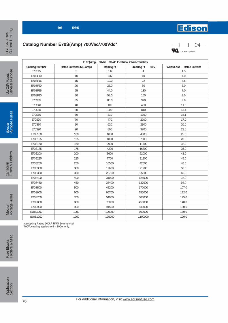
76
ee ses
For additional information, visit www.edisonfuse.com
Med
ium
Volta
ge F
uses
UL/C
SA F
uses
Curr
ent L
imiti
ngUL
/CSA
Fus
esGe
nera
l Pur
pose
Spec
ial
Purp
ose
Fuse
sCa
nadi
anFu
ses
& Ho
lder
sAp
plic
atio
nSe
ctio
nFu
se B
lock
s,Ho
lder
s &
Mis
c.
Catalog Number E70S(Amp) 700Vac/700Vdc*
E 0S(Amp) 00Vac 00Vdc Electrical CharacteristicsCatalog Number Rated Current RMS Amps Melting I2t Clearing I2t 00V Watts Loss Rated Current
E70SF5 5 1.6 4 1.5E70SF10 10 3.6 10 4.0E70SF15 15 10.0 22 5.5E70SF20 20 26.0 60 6.0E70SF25 25 44.0 130 7.0E70SF30 30 58.0 150 9.0E70S35 35 80.0 370 9.8E70S40 40 100 460 11.5E70S50 50 200 840 13.4E70S60 60 310 1300 15.1E70S70 70 470 2200 17.0E70S80 80 620 2900 20.0E70S90 90 800 3700 23.0E70S100 100 1030 4800 25.0E70S125 125 1800 7300 28.0E70S150 150 2900 11700 32.0E70S175 175 4200 16700 35.0E70S200 200 5600 22000 43.0E70S225 225 7700 31300 45.0E70S250 250 10500 42500 48.0E70S300 300 17600 71200 58.0E70S350 350 23700 95600 65.0E70S400 400 31000 125000 78.0E70S450 450 36400 137000 94.0E70S500 500 45200 170000 107.0E70S600 600 66700 250000 122.0E70S700 700 54000 300000 125.0E70S800 800 78000 450000 140.0E70S900 900 91500 530000 150.0
E70S1000 1000 120000 600000 170.0E70S1200 1200 195000 1100000 190.0
UL Recognized
Interrupting Rating 200kA RMS Symmetrical*700Vdc rating applies to 5 – 800A only.

Circuit Protection
77For additional information, visit www.edisonfuse.com
ee ses
AMP RATING
CURRENT IN AMPS
100101
1,00
0
5A 10A
15A
20A
25A
30A
10
100
TIM
E IN
SE
CO
ND
S
1
.1
.01
AMP RATING
CURRENT IN AMPS
1,00
0
10010
10,0
00
600A
100
1,000
400A
300A
200A
150A
100A
80A
60A
50A
35A
TIM
E IN
SE
CO
ND
S10
1
.1
A
B
AM
PR
ATIN
G
10,000
1,000
100
10
10 100
1,00
0
2,00
0
RMS SYMMETRICAL CURRENTS IN AMPSA–B=ASYMMETRICAL AVAILABLE PEAK (2.3 X SYMM RMS AMPS)
INS
TAN
TAN
EO
US
PE
AK
LE
T-TH
RO
UG
H C
UR
RE
NT
IN A
MP
S
15
10
5
202530
A
B
AM
PR
ATIN
G
100,000
10,000
1,000
100
100
1,00
0
10,0
00
20,0
00
RMS SYMMETRICAL CURRENTS IN AMPSA–B=ASYMMETRICAL AVAILABLE PEAK (2.3 X SYMM RMS AMPS)
INS
TAN
TAN
EO
US
PE
AK
LE
T-TH
RO
UG
H C
UR
RE
NT
IN A
MP
S
600
150
400300
200
10080605035
Pre-Arcing Time-Current Curves
E70SF(Amp)5 – 30A, 700V
Minimum Melt Time-Current Curves
E70S(Amp)35 – 600A, 700V
Peak Let-Through Current Curves
E70SF(Amp)5 – 30A, 700V
E70S(Amp)35 – 600A, 700V
Medium
Voltage FusesUL/CSA FusesCurrent Lim
itingUL/CSA FusesGeneral Purpose
SpecialPurpose Fuses
CanadianFuses & Holders
ApplicationSection
Fuse Blocks,Holders & M
isc.

78
ee ses
For additional information, visit www.edisonfuse.com
Med
ium
Volta
ge F
uses
UL/C
SA F
uses
Curr
ent L
imiti
ngUL
/CSA
Fus
esGe
nera
l Pur
pose
Spec
ial
Purp
ose
Fuse
sCa
nadi
anFu
ses
& Ho
lder
sAp
plic
atio
nSe
ctio
nFu
se B
lock
s,Ho
lder
s &
Mis
c.
AMP RATING
CURRENT IN AMPS
1,00
0
10040
10,0
00
30,0
00
700A
800A
1000
A12
00A
10
100
TIM
E IN
SE
CO
ND
S
1
.1
.01
A
AM
PR
ATIN
G
100,000
10,000
1,000
100
100
1,00
0
10,0
00
20,0
00
RMS SYMMETRICAL CURRENTS IN AMPSA–B=ASYMMETRICAL AVAILABLE PEAK (2.3 X SYMM RMS AMPS)
INS
TAN
TAN
EO
US
PE
AK
LE
T-TH
RO
UG
H C
UR
RE
NT
IN A
MP
S B
70080010001200
Minimum Melt Time-Current Curves
E70S(Amp)700 – 1200A, 700V
Peak Let-Through Current Curves
E70S(Amp)700 – 1200A, 700V

Circuit Protection
79For additional information, visit www.edisonfuse.com
ee ses
Catalog Number E100SF(20 – 30A) 1000Vac/800Vdc
Catalog Number E100S(40 – 800A) 1000Vac/700Vdc
H
B
J
CEDA
G
F
Figure 1: 40 – 800A Range
E100S(Amp) Dimensions - inches (mm)Catalog Numbers Figure A B C D E F G
E100S40 – 60 1 5.00 (127.0) 0.94 (23.9) 3.11 (79.0) 4.24 (107.6) 4.18 (106.2) 0.35 (8.9) 0.75 (19.1) 0.13 (3.2) 0.38 (9.7)E100S70 – 100 1 4.93 (125.3) 1.13 (28.6) 3.09 (78.4) 4.27 (108.4) 4.16 (105.6) 0.35 (8.9) 1.00 (25.4) 0.19 (4.8) 0.41 (10.3)E100S125 – 200 1 5.69 (144.4) 1.53 (38.8) 3.26 (82.8) 4.63 (117.6) 4.58 (116.4) 0.45 (11.3) 1.00 (25.4) 0.25 (6.4) 0.47 (11.9)E100S250 – 400 1 5.77 (146.5) 2.00 (50.8) 3.50 (88.9) 4.81 (122.2) 4.15 (105.4) 0.43911.0) 1.50 (38.1) 0.25 (6.4) 0.76 (19.4)E100S500 – 600 1 7.20 (182.9) 2.50 (63.5) 3.47 (88.0) 5.98 (152.0) 4.71 (119.5) 0.56 (14.3) 2.00 (50.8) 0.38 (9.5) 1.20 (30.5)
E100S800 1 6.81 (173.0) 3.50 (88.9) 3.31 (84.1) 5.47 (139.0) 4.96 (126.0) 0.63 (15.9) 2.75 (69.9) 0.50 (12.7) 0.88 (22.4)
0.625"15.9mm
2.626"66.7mm
0.571"14.5mm
Dimensions - inches (mm)E100SF(AMP) Dimensions - inches (mm)Catalog Numbers E100SF20 – 30 See Drawing
Medium
Voltage FusesUL/CSA FusesCurrent Lim
itingUL/CSA FusesGeneral Purpose
SpecialPurpose Fuses
CanadianFuses & Holders
ApplicationSection
Fuse Blocks,Holders & M
isc.

80
ee ses
For additional information, visit www.edisonfuse.com
Med
ium
Volta
ge F
uses
UL/C
SA F
uses
Curr
ent L
imiti
ngUL
/CSA
Fus
esGe
nera
l Pur
pose
Spec
ial
Purp
ose
Fuse
sCa
nadi
anFu
ses
& Ho
lder
sAp
plic
atio
nSe
ctio
nFu
se B
lock
s,Ho
lder
s &
Mis
c.
Catalog Number E100S(Amp) 1000Vac/700Vdc*
E100S(Amp) 1000Vac 00Vdc Electrical CharacteristicsCatalog Number Rated Current RMS Amps Melting I2t Clearing I2t 1000V Watts Loss Rated Current
E100SF20 20 25.0 220 9.0E100SF25 25 33.0 350 11.0E100SF30 30 52.0 450 14.0E100S40 40 300 2500 9.8E100S50 50 470 3500 8.0E100S60 60 670 5000 10.0E100S70 70 1100 6900 11.0E100S80 80 1550 9700 12.0E100S90 90 1900 12000 13.0E100S100 100 2800 17500 14.0E100S125 125 4800 35000 15.0E100S150 150 6300 45000 16.0E100S175 175 7500 65000 25.0E100S200 200 11700 80000 30.0E100S250 250 9000 50000 32.0E100S300 300 15000 80000 50.0E100S350 350 22000 120000 56.0E100S400 400 32000 180000 62.0E100S500 500 28500 155000 95.0E100S600 600 646500 260000 105.0E100S800 800 87000 500000 182.0
UL Recognized†
Interrupting Rating 200kA RMS Symmetrical*Amp ratings 20 – 500 rated up to 800Vdc.†UL Recognition through 200A only.

Circuit Protection
81For additional information, visit www.edisonfuse.com
ee ses
AMP RATING
CURRENT IN AMPS
1,00
0
10010
10,0
00
20A
30A
25A
10
100
TIM
E IN
SE
CO
ND
S
1
.1
.01
AMP RATING
CURRENT IN AMPS
1,00
0
10010
10,0
00
40A
50A
60A
80A
70A
90A
100A
125A
150A
250A
600A
500A
400A
350A
300A
200A
10
100
TIM
E IN
SE
CO
ND
S1
.1
.01
A
AMP
RATI
NG
10 000
1 000
100
10
10 100
100
0
200
0
RMS S MMETRICAL CURRENTS IN AMPSA B AS MMETRICAL AVAILABLE PEAK (2. S MM RMS AMPS)
INST
ANTA
NEOU
S PE
AK L
ET-T
ROUG
CUR
RENT
IN A
MPS
B
02520
A
100,000
10,000
1,000
100
100
1,00
0
10,0
00
RMS SYMMETRICAL CURRENTS IN AMPSA–B=ASYMMETRICAL AVAILABLE PEAK (2.3 X SYMM RMS AMPS)
INST
ANTA
NEO
US
PEAK
LET
-TH
RO
UG
H C
UR
REN
T IN
AM
PS
50,0
00AM
PR
ATIN
G
B
600500 & 400
350 300250
200175
150125100908070605040
Pre-Arcing Time-Current Curves
E100SF(Amp)20 – 30A, 1000Vac/800Vdc
Minimum Melt Time-Current Curves
E100S(Amp)40 – 600A, 1000Vac/700Vdc
Peak Let-Through Current Curves
E100SF(Amp)20 – 30A
E100S(Amp)40 – 600A
Medium
Voltage FusesUL/CSA FusesCurrent Lim
itingUL/CSA FusesGeneral Purpose
SpecialPurpose Fuses
CanadianFuses & Holders
ApplicationSection
Fuse Blocks,Holders & M
isc.

82
t s t le ee ses
For additional information, visit www.edisonfuse.com
Med
ium
Volta
ge F
uses
UL/C
SA F
uses
Curr
ent L
imiti
ngUL
/CSA
Fus
esGe
nera
l Pur
pose
Spec
ial
Purp
ose
Fuse
sCa
nadi
anFu
ses
& Ho
lder
sAp
plic
atio
nSe
ctio
nFu
se B
lock
s,Ho
lder
s &
Mis
c.
IntroductionBritish BS 88 Contents
Accessories
• Indicator System (see end of this section)
• Fuse Blocks (see BH Series fuse blocks in this catalog)
British BS 88 Fuse Ranges
General Information
Designed and tested to:
• BS 88: Part 4
• IEC 269: Part 4
• UL Recognized
We offer the industry’s widest range of British style semiconductor fuses and accessories.
Edison British style products use innovative arc quenchingtechniques and high grade materials to provide:
• Minimal energy let-through (I2t)
• Excellent DC performance
• Good surge withstand profile
British style fuses are typically found in equipment manufactured in the United Kingdom or BritishCommonwealth countries. However, North American manufacturers have begun to specify British style fuses —particularly in UPS applications at 240V or less — to takeadvantage of their size, performance and cost benefits.
Fuse Volts Amp Range240 6-900690 6-710
Amps Volts AC DC6-900 240 X —6-900 150 — X6-700 690 X —6-700 500 — X
Voltage Rating
All Edison British style fuses are tested to IEC 269: Part 4.This standard requires a test voltage which is 5% higherthan the rated voltage. In North America, fuses are requiredto clear only their rated voltage.
Accessories
Trip-indicator fuses are available for use in parallel with themain fuse. Indicator fuses can be attached to the associated fuse, or mounted separately in panel-mountedfuseclips. In addition, a push-on adapter and microswitchattachment are available, to provide remote indication. The BH Series fuse blocks are also available for mostapplications.
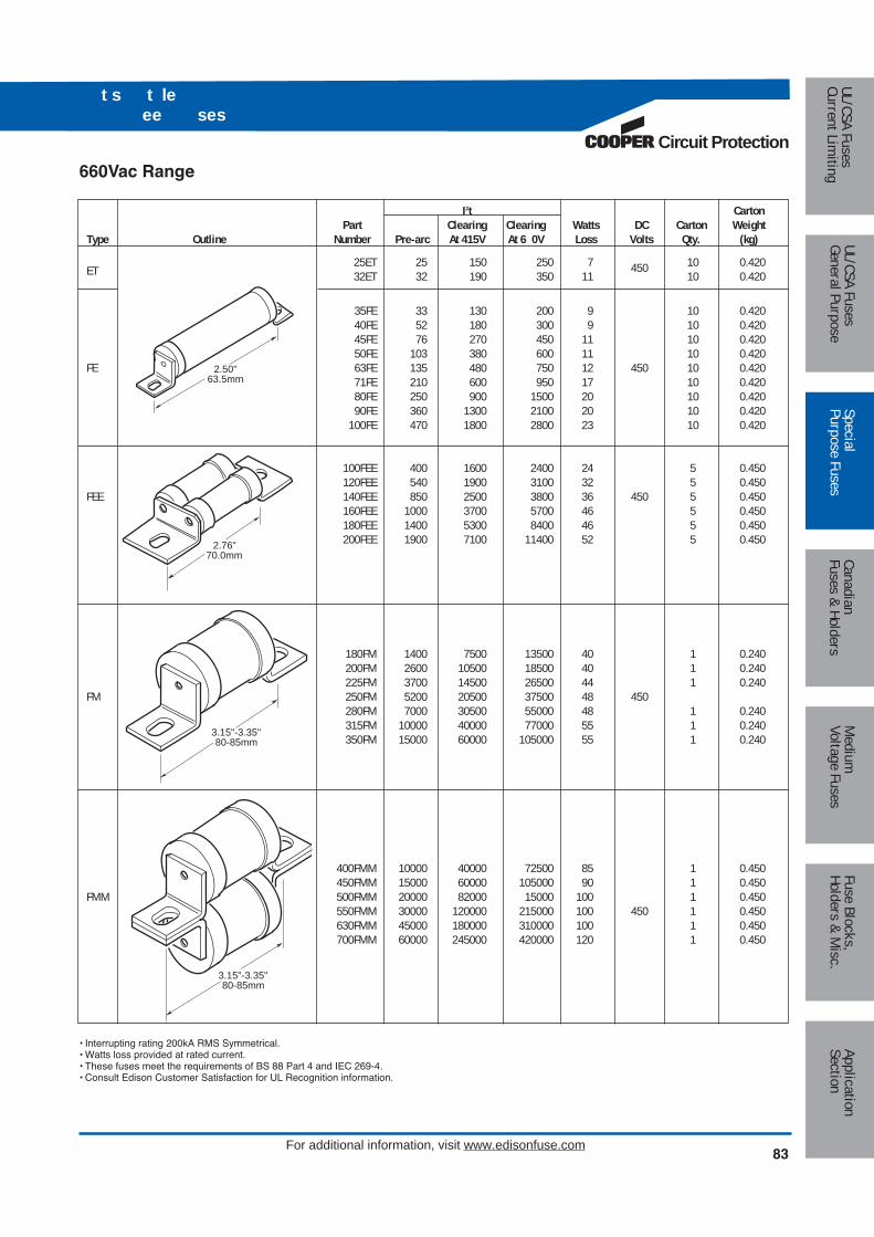
Circuit Protection
83For additional information, visit www.edisonfuse.com
t s t le ee ses
I2t CartonPart Clearing Clearing Watts DC Carton Weight
Type Outline Number Pre-arc At 415V At 6 0V Loss Volts Qty. (kg)
25ET 25 150 250 7 450 10 0.420ET 32ET 32 190 350 11 10 0.420
35FE 33 130 200 9 10 0.42040FE 52 180 300 9 10 0.42045FE 76 270 450 11 10 0.42050FE 103 380 600 11 10 0.420
FE 63FE 135 480 750 12 450 10 0.42071FE 210 600 950 17 10 0.42080FE 250 900 1500 20 10 0.42090FE 360 1300 2100 20 10 0.420
100FE 470 1800 2800 23 10 0.420
100FEE 400 1600 2400 24 5 0.450120FEE 540 1900 3100 32 5 0.450
FEE 140FEE 850 2500 3800 36 450 5 0.450160FEE 1000 3700 5700 46 5 0.450180FEE 1400 5300 8400 46 5 0.450200FEE 1900 7100 11400 52 5 0.450
180FM 1400 7500 13500 40 1 0.240200FM 2600 10500 18500 40 1 0.240225FM 3700 14500 26500 44 1 0.240
FM 250FM 5200 20500 37500 48 450280FM 7000 30500 55000 48 1 0.240315FM 10000 40000 77000 55 1 0.240350FM 15000 60000 105000 55 1 0.240
400FMM 10000 40000 72500 85 1 0.450450FMM 15000 60000 105000 90 1 0.450
FMM 500FMM 20000 82000 15000 100 1 0.450550FMM 30000 120000 215000 100 450 1 0.450630FMM 45000 180000 310000 100 1 0.450700FMM 60000 245000 420000 120 1 0.450
2.50"63.5mm
2.76"70.0mm
3.15"-3.35"80-85mm
3.15"-3.35"80-85mm
660Vac Range
• Interrupting rating 200kA RMS Symmetrical.• Watts loss provided at rated current.• These fuses meet the requirements of BS 88 Part 4 and IEC 269-4.• Consult Edison Customer Satisfaction for UL Recognition information.
Medium
Voltage FusesUL/CSA FusesCurrent Lim
itingUL/CSA FusesGeneral Purpose
SpecialPurpose Fuses
CanadianFuses & Holders
ApplicationSection
Fuse Blocks,Holders & M
isc.
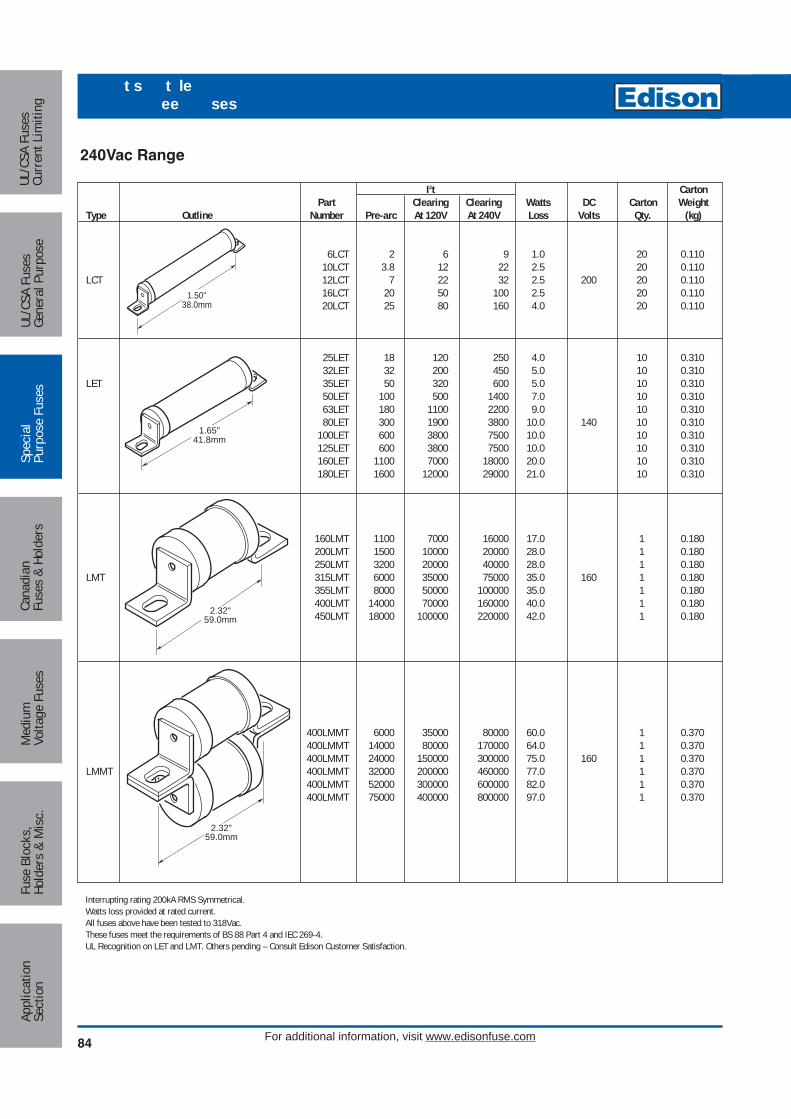
84
t s t le ee ses
For additional information, visit www.edisonfuse.com
Med
ium
Volta
ge F
uses
UL/C
SA F
uses
Curr
ent L
imiti
ngUL
/CSA
Fus
esGe
nera
l Pur
pose
Spec
ial
Purp
ose
Fuse
sCa
nadi
anFu
ses
& Ho
lder
sAp
plic
atio
nSe
ctio
nFu
se B
lock
s,Ho
lder
s &
Mis
c.
I2t CartonPart Clearing Clearing Watts DC Carton Weight
Type Outline Number Pre-arc At 120V At 240V Loss Volts Qty. (kg)
6LCT 2 6 9 1.0 20 0.11010LCT 3.8 12 22 2.5 20 0.110
LCT 12LCT 7 22 32 2.5 200 20 0.11016LCT 20 50 100 2.5 20 0.11020LCT 25 80 160 4.0 20 0.110
25LET 18 120 250 4.0 10 0.31032LET 32 200 450 5.0 10 0.310
LET 35LET 50 320 600 5.0 10 0.31050LET 100 500 1400 7.0 10 0.31063LET 180 1100 2200 9.0 10 0.31080LET 300 1900 3800 10.0 140 10 0.310
100LET 600 3800 7500 10.0 10 0.310125LET 600 3800 7500 10.0 10 0.310160LET 1100 7000 18000 20.0 10 0.310180LET 1600 12000 29000 21.0 10 0.310
160LMT 1100 7000 16000 17.0 1 0.180200LMT 1500 10000 20000 28.0 1 0.180250LMT 3200 20000 40000 28.0 1 0.180
LMT 315LMT 6000 35000 75000 35.0 160 1 0.180355LMT 8000 50000 100000 35.0 1 0.180400LMT 14000 70000 160000 40.0 1 0.180450LMT 18000 100000 220000 42.0 1 0.180
400LMMT 6000 35000 80000 60.0 1 0.370400LMMT 14000 80000 170000 64.0 1 0.370400LMMT 24000 150000 300000 75.0 160 1 0.370
LMMT 400LMMT 32000 200000 460000 77.0 1 0.370400LMMT 52000 300000 600000 82.0 1 0.370400LMMT 75000 400000 800000 97.0 1 0.370
1.50"38.0mm
1.65"41.8mm
2.32"59.0mm
2.32"59.0mm
240Vac Range
Interrupting rating 200kA RMS Symmetrical. Watts loss provided at rated current. All fuses above have been tested to 318Vac. These fuses meet the requirements of BS 88 Part 4 and IEC 269-4. UL Recognition on LET and LMT. Others pending – Consult Edison Customer Satisfaction.
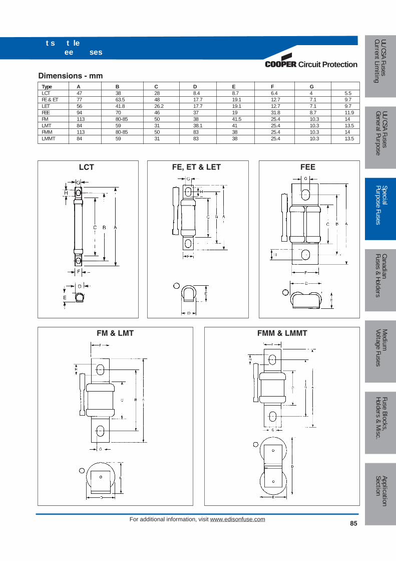
Circuit Protection
85For additional information, visit www.edisonfuse.com
t s t le ee ses
LCT
FM & LMT FMM & LMMT
FE, ET & LET FEE
Dimensions - mmType A B C D E F GLCT 47 38 28 8.4 8.7 6.4 4 5.5FE & ET 77 63.5 48 17.7 19.1 12.7 7.1 9.7LET 56 41.8 26.2 17.7 19.1 12.7 7.1 9.7FEE 94 70 46 37 19 31.8 8.7 11.9FM 113 80-85 50 38 41.5 25.4 10.3 14LMT 84 59 31 38.1 41 25.4 10.3 13.5FMM 113 80-85 50 83 38 25.4 10.3 14LMMT 84 59 31 83 38 25.4 10.3 13.5
Medium
Voltage FusesUL/CSA FusesCurrent Lim
itingUL/CSA FusesGeneral Purpose
SpecialPurpose Fuses
CanadianFuses & Holders
ApplicationSection
Fuse Blocks,Holders & M
isc.
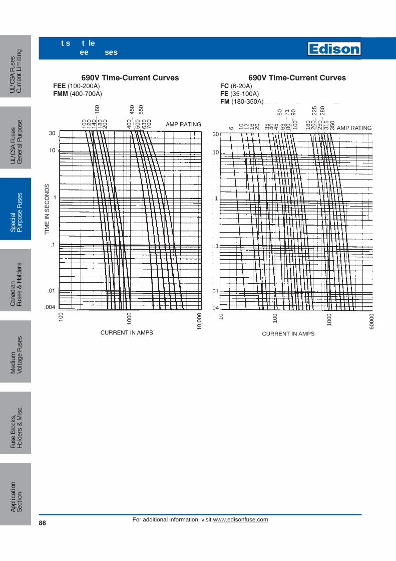
86
t s t le ee ses
For additional information, visit www.edisonfuse.com
Med
ium
Volta
ge F
uses
UL/C
SA F
uses
Curr
ent L
imiti
ngUL
/CSA
Fus
esGe
nera
l Pur
pose
Spec
ial
Purp
ose
Fuse
sCa
nadi
anFu
ses
& Ho
lder
sAp
plic
atio
nSe
ctio
nFu
se B
lock
s,Ho
lder
s &
Mis
c.
AMP RATING350
280
250
225
315
6 10 12 16 20 634550 71
8090
100
4035 200
180
.1
01
04
30
10
1
CURRENT IN AMPS
6000
010 100
1000
AMP RATING700
550
500
450
400
630
100
120
140
160
180
200
CURRENT IN AMPS
10,0
00100
1000
.1
.01
TIM
E IN
SE
CO
ND
S
.004
30
10
1
690V Time-Current CurvesFC (6-20A)FE (35-100A)FM (180-350A)
690V Time-Current CurvesFEE (100-200A)FMM (400-700A)
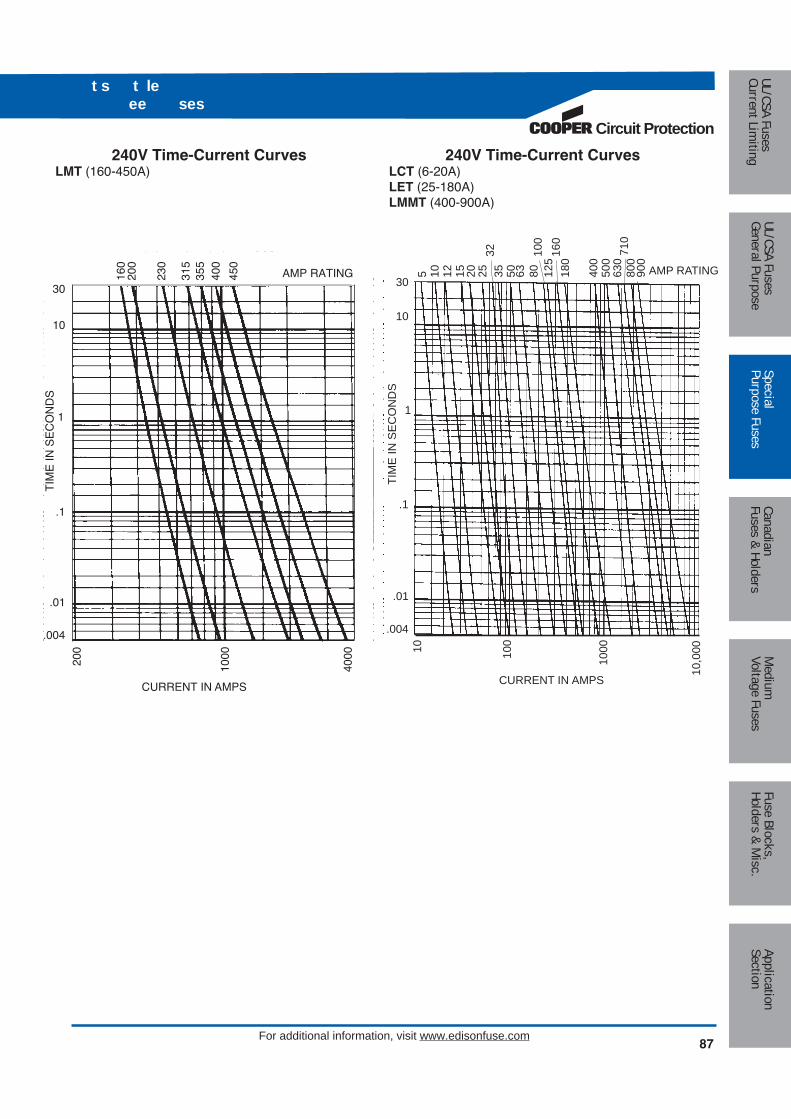
Circuit Protection
87For additional information, visit www.edisonfuse.com
t s t le ee ses
240V Time-Current CurvesLCT (6-20A)LET (25-180A)LMMT (400-900A)
AMP RATING500
630
180
160
125
400
5 20 2532
35 5010 12 15 63 8010
0
710
800
900
CURRENT IN AMPS10
,00010
0
1000
.1
.01
TIM
E IN
SE
CO
ND
S
.004
30
10
110
160
315
355
450
.1
.01
TIM
E IN
SE
CO
ND
S
.004
30
10
1
AMP RATING200
230
400
CURRENT IN AMPS
200
1000
4000
240V Time-Current CurvesLMT (160-450A)
Medium
Voltage FusesUL/CSA FusesCurrent Lim
itingUL/CSA FusesGeneral Purpose
SpecialPurpose Fuses
CanadianFuses & Holders
ApplicationSection
Fuse Blocks,Holders & M
isc.

88
t s t le ee sesn ato s esso es
For additional information, visit www.edisonfuse.com
Med
ium
Volta
ge F
uses
UL/C
SA F
uses
Curr
ent L
imiti
ngUL
/CSA
Fus
esGe
nera
l Pur
pose
Spec
ial
Purp
ose
Fuse
sCa
nadi
anFu
ses
& Ho
lder
sAp
plic
atio
nSe
ctio
nFu
se B
lock
s,Ho
lder
s &
Mis
c.
Indicator System
Trip-IndicatorsTrip-indicators are available for use in parallel with the mainfuse. They can either be attached to the associated fuse ormounted separately in panel mounted fuse clips, referenceCL1. A push-on adapter and microswitch attachment isavailable for use with the trip indicator to give the facility ofremote indication, reference MAI.
Fuse ratings of 20A and below cannot usually accommodate a trip-indicator.
When a trip-indicator is to be attached to the main fuse anaccessory pack comprising a pair of mounting clips and anappropriate trip indicator would be required. The clips aresnapped onto the fuse end caps and the indicator ispressed into clips as shown.
Electrical Specifications
Type TI500 TI 00Maximum RMS Voltage 500 700Maximum Peak Voltage 700 1000Maximum DC Voltage 130 350Cold Resistance (ohms) 0.3 0.45Maximum permissible steady-state current 1.5A 1.5AInterrupting Capacity (RMS Symm.) 100,000 100,000Pre-Arcing I2t 23 23
Microswitch Adapter – MAIWe offer a microswitch, complete with adapter for securing the indicator. The microswitch is provided withdouble pole, single throw contacts, having both a normallyopen and a normally closed position. A special material hasbeen employed in the construction of the adapter to providereliable operation in the range of temperatures associatedwith standard operating conditions and during fuse operation.
Microswitch and Adapter Type MAI
Current RatingAC 50/60H resistive load 250V RMS 4AAC 50/60H resistive load 127V RMS 6ADC, resistive load 110Vdc 0.7A DCDC, resistive load 30Vdc 2A DC
Maximum Working VoltageContact-to-contact (RMS) 1000VContact-to-contact (RMS) 1500V
Maximum DC Volts 110Vdc
Ref. Dim. A (mm) RMS VoltsTI250 37.6 250TI500 47.5 500TI600 55.7 600TI700 61.8 700TI1100 98.4 1100TI1500 120.6 1500TI2000 147.5 2000TI2500 198.3 2500
RMS For useKit. Ref. Details Volts with Fuse Ref.EC-250 Fuse Mount 250 LETMC250 Indicator Kits 250 LMT & LMMTEC-600 (Includes one 660 FE, FEE & ETMC600 indicator 660 FM & FMMMC700 and two clips) 700 MT & MMT
EC
A
B
D
F6 21 0.8
6.8
6.35
NONC
NCNO
Terminal Arrangement
Trip-Indicator Dimensions - mm
Dimensions in mm
Fuse Indicator Kits
6.0 8.7
50.8
B
14
CL1 Panel Mount Clips
CL1 Panel mount fuse clips are available for mounting atrip-indicator when mounting directly on the fuse is impractical. Order part number CL1.
CL1 Panel Mount Clip Dimensions - mm

CROSS REFERENCEEDISON LINDNER SIEMENS EAN MULLER2D16 594-0027 5SA2-11 gTN D /24D16 594-0047 5SA2-21 gTN D /46D16 594-0067 5SA2-31 gTN D /610D16 594-0107 5SA2-51 gTN D /1016D16 594-0167 5SA2-61 gTN D /1620D16 594-0207 5SA2-71 gTN D /2025D16 594-0257 5SA2-81 gTN D /252D27 597-0027 5SB2-11 gLD 2/24D27 597-0047 5SB2-21 gLD 2/46D27 597-0067 5SB2-31 gLD 2/610D27 597-0107 5SB2-51 gLD 2/1016D27 597-0167 5SB2-61 gLD 2/1620D27 597-0207 5SB2-71 gLD 2/2025D27 597-0257 5SB2-81 gLD 2/2535D33 598-0357 5SB4-11 gLD 3/3550D33 598-0357 5SB4-11 gLD 3/3563D33 598-0357 5SB4-11 gLD 3/3580D125 595-0807 5SC2-11 gLD 4/80100D125 595-1007 5SC2-21 gLD 4/100
Circuit Protection
89For additional information, visit www.edisonfuse.com
Type D “Bottle” FuseAmp Ratings: 2 to 100AVoltage Ratings: 500VacInterrupting Rating: 100kAAgency Approvals:“D” type fuses complying with DIN 49360 (time lag) 2 andDIN 49515, operating class gG/gL
Catalog Dimension Ampere Color FigureNumber D Rating Code Number2D16 6 2 Pink4D16 6 4 Brown6D16 6 6 Green10D16 8 10 Red 116D16 10 16 Gray20D16 12 20 Blue25D16 14 25 Yellow2D27 6 2 Pink4D27 6 4 Brown6D27 6 6 Green10D27 8 10 Red 216D27 10 16 Gray20D27 12 20 Blue25D27 14 25 Yellow35D33 16 35 Black50D33 18 50 White 363D33 20 63 Copper80D125 5 80 Silver 4100D125 7 100 Red
Additional fuse links Quick acting fuse links in body si e D16, D27, D33 andD125 rated 2-100A. Reference number with suffix Q , i.e. 10D27Q. Voltagerating 500V ultra fast-acting fuse links in body si e D27, D33, and D125rated 6-100A. Reference number with suffix R , i.e., 10D27R.Notes (a) Gauge rings and keys can also be supplied.
Neozed FuseAlso suitable for use on 250Vdc systems.Amp Ratings: 2 to 63AVoltage Ratings: 400VacInterrupting Rating: 100kA
Catalog Dimension Contact Amp ColorNumber D Diameter D1 Rating Code2N 01 11 7.3 2 Pink4N 01 11 7.3 4 Brown6N 01 11 7.3 6 Green10N 01 11 8.5 10 Red16N 01 11 9.7 16 Gray20N 02 15 10.9 20 Blue25N 02 15 12.1 25 Yellow35N 02 15 13.3 35 Black50N 02 15 14.5 50 White63N 02 15 15.9 63 Copper
Figure 1 Figure 2 Figure 3 Figure 4
t s Cana an tan an st al ses
Dimensions - mm
Dimensions - mm
Medium
Voltage FusesUL/CSA FusesCurrent Lim
itingUL/CSA FusesGeneral Purpose
SpecialPurpose Fuses
CanadianFuses & Holders
ApplicationSection
Fuse Blocks,Holders & M
isc.
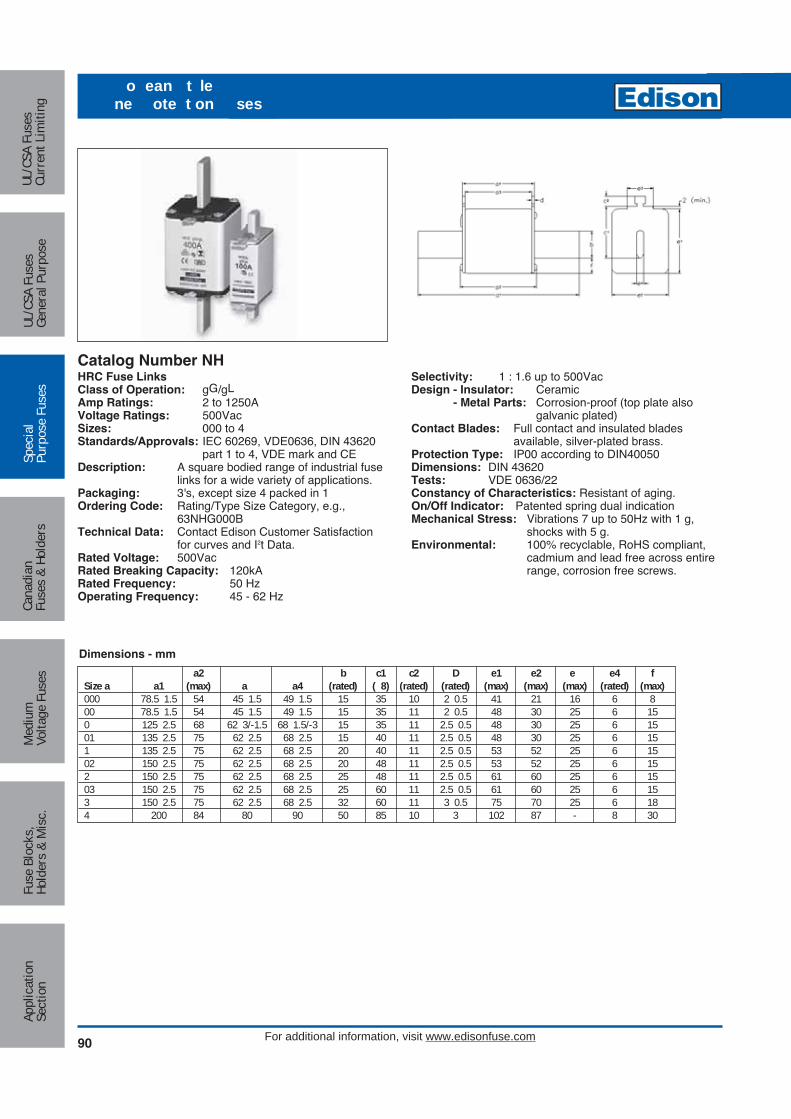
90
o ean t lene ote t on ses
For additional information, visit www.edisonfuse.com
Med
ium
Volta
ge F
uses
UL/C
SA F
uses
Curr
ent L
imiti
ngUL
/CSA
Fus
esGe
nera
l Pur
pose
Spec
ial
Purp
ose
Fuse
sCa
nadi
anFu
ses
& Ho
lder
sAp
plic
atio
nSe
ctio
nFu
se B
lock
s,Ho
lder
s &
Mis
c.
Catalog Number NHHRC Fuse LinksClass of Operation: gG/gLAmp Ratings: 2 to 1250AVoltage Ratings: 500VacSizes: 000 to 4Standards/Approvals: IEC 60269, VDE0636, DIN 43620
part 1 to 4, VDE mark and CEDescription: A square bodied range of industrial fuse
links for a wide variety of applications.Packaging: 3's, except size 4 packed in 1Ordering Code: Rating/Type Size Category, e.g.,
63NHG000BTechnical Data: Contact Edison Customer Satisfaction
for curves and I2t Data.Rated Voltage: 500VacRated Breaking Capacity: 120kARated Frequency: 50 HzOperating Frequency: 45 - 62 Hz
Selectivity: 1 : 1.6 up to 500VacDesign - Insulator: Ceramic
- Metal Parts: Corrosion-proof (top plate alsogalvanic plated)
Contact Blades: Full contact and insulated blades available, silver-plated brass.
Protection Type: IP00 according to DIN40050 Dimensions: DIN 43620Tests: VDE 0636/22Constancy of Characteristics: Resistant of aging.On/Off Indicator: Patented spring dual indicationMechanical Stress: Vibrations 7 up to 50Hz with 1 g,
shocks with 5 g.Environmental: 100% recyclable, RoHS compliant,
cadmium and lead free across entire range, corrosion free screws.
Dimensions - mm
a2 b c1 c2 D e1 e2 e e4 fSize a a1 (max) a a4 (rated) ( 8) (rated) (rated) (max) (max) (max) (rated) (max)000 78.5 1.5 54 45 1.5 49 1.5 15 35 10 2 0.5 41 21 16 6 800 78.5 1.5 54 45 1.5 49 1.5 15 35 11 2 0.5 48 30 25 6 150 125 2.5 68 62 3/-1.5 68 1.5/-3 15 35 11 2.5 0.5 48 30 25 6 1501 135 2.5 75 62 2.5 68 2.5 15 40 11 2.5 0.5 48 30 25 6 151 135 2.5 75 62 2.5 68 2.5 20 40 11 2.5 0.5 53 52 25 6 1502 150 2.5 75 62 2.5 68 2.5 20 48 11 2.5 0.5 53 52 25 6 152 150 2.5 75 62 2.5 68 2.5 25 48 11 2.5 0.5 61 60 25 6 1503 150 2.5 75 62 2.5 68 2.5 25 60 11 2.5 0.5 61 60 25 6 153 150 2.5 75 62 2.5 68 2.5 32 60 11 3 0.5 75 70 25 6 184 200 84 80 90 50 85 10 3 102 87 - 8 30
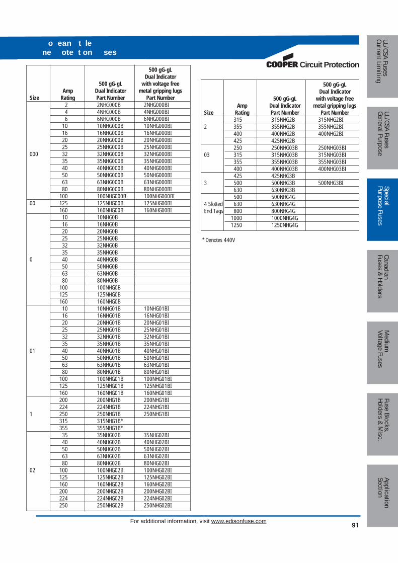
Circuit Protection
91
Medium
Voltage FusesUL/CSA FusesCurrent Lim
itingUL/CSA FusesGeneral Purpose
SpecialPurpose Fuses
CanadianFuses & Holders
ApplicationSection
Fuse Blocks,Holders & M
isc.
o ean t lene ote t on ses
For additional information, visit www.edisonfuse.com
500 gG-gLDual Indicator
500 gG-gL with voltage freeAmp Dual Indicator metal gripping lugs
Size Rating Part Number Part Number2 2NHG000B 2NHG000BI4 4NHG000B 4NHG000BI6 6NHG000B 6NHG000BI
10 10NHG000B 10NHG000BI16 16NHG000B 16NHG000BI20 20NHG000B 20NHG000BI25 25NHG000B 25NHG000BI
000 32 32NHG000B 32NHG000BI35 35NHG000B 35NHG000BI40 40NHG000B 40NHG000BI50 50NHG000B 50NHG000BI63 63NHG000B 63NHG000BI80 80NHG000B 80NHG000BI
100 100NHG000B 100NHG000BI00 125 125NHG00B 125NHG00BI
160 160NHG00B 160NHG00BI10 10NHG0B16 16NHG0B20 20NHG0B25 25NHG0B32 32NHG0B35 35NHG0B
0 40 40NHG0B50 50NHG0B63 63NHG0B80 80NHG0B
100 100NHG0B125 125NHG0B160 160NHG0B10 10NHG01B 10NHG01BI16 16NHG01B 16NHG01BI20 20NHG01B 20NHG01BI25 25NHG01B 25NHG01BI32 32NHG01B 32NHG01BI35 35NHG01B 35NHG01BI
01 40 40NHG01B 40NHG01BI50 50NHG01B 50NHG01BI63 63NHG01B 63NHG01BI80 80NHG01B 80NHG01BI
100 100NHG01B 100NHG01BI125 125NHG01B 125NHG01BI160 160NHG01B 160NHG01BI200 200NHG1B 200NHG1BI224 224NHG1B 224NHG1BI
1 250 250NHG1B 250NHG1BI315 315NHG1B*355 355NHG1B*35 35NHG02B 35NHG02BI40 40NHG02B 40NHG02BI50 50NHG02B 50NHG02BI63 63NHG02B 63NHG02BI80 80NHG02B 80NHG02BI
02 100 100NHG02B 100NHG02BI125 125NHG02B 125NHG02BI160 160NHG02B 160NHG02BI200 200NHG02B 200NHG02BI224 224NHG02B 224NHG02BI250 250NHG02B 250NHG02BI
500 gG-gLDual Indicator
500 gG-gL with voltage freeAmp Dual Indicator metal gripping lugs
Size Rating Part Number Part Number315 315NHG2B 315NHG2BI
2 355 355NHG2B 355NHG2BI400 400NHG2B 400NHG2BI425 425NHG2B250 250NHG03B 250NHG03BI
03 315 315NHG03B 315NHG03BI355 355NHG03B 355NHG03BI400 400NHG03B 400NHG03BI425 425NHG3B
3 500 500NHG3B 500NHG3BI630 630NHG3B500 500NHG4G
4 Slotted 630 630NHG4GEnd Tags 800 800NHG4G
1000 1000NHG4G1250 1250NHG4G
* Denotes 440V

Med
ium
Volta
ge F
uses
UL/C
SA F
uses
Curr
ent L
imiti
ngUL
/CSA
Fus
esGe
nera
l Pur
pose
Spec
ial
Purp
ose
Fuse
sCa
nadi
anFu
ses
& Ho
lder
sAp
plic
atio
nSe
ctio
nFu
se B
lock
s,Ho
lder
s &
Mis
c.
For additional information, visit www.edisonfuse.com92
Time-DelayVolts Ref. Amp Ratings Ctn. Qty.
Below 10A use ECSR10, 12, 15, 20, 25, 30, 1035, 40, 45, 50, 60
600Vac CDSC* 70, 80, 90, 100 5110, 125, 150, 175, 200,225, 250, 300, 350, 400, 1450, 500, 600Below 10A use ECNR10, 12, 15, 20, 25, 30, 1035, 40, 45, 50, 60
250Vac CDNC* 70, 80, 90, 100 5110, 125, 150, 175, 200,225, 250, 300, 350, 400, 1450, 500, 600
One-TimeVolts Ref. Amp Ratings Ctn. Qty.
1, 2, 3, 4, 5, 6, 7, 8,10, 12, 15, 20, 25, 30 1035, 40, 45, 50, 60
600Vac KOS** 70, 80, 90, 100 5110, 125, 150, 175, 200,225, 250, 300, 350, 400, 1450, 500, 600
KON** 1, 2, 3, 4, 5, 6, 7, 8, 10, 12
PONC*** 15, 20, 25, 30, (CSA P ) 1035, 40, 45, 50, 60
250Vac 70, 80, 90, 100 5
KON 110, 125, 150, 175, 200,225, 250, 300, 350, 400, 1450, 500, 600
CatalogVolts Number Amps Max. A Min. B Min. C D E F
1-30 2.0 (50.8) 0.56 (14.3) – – – –CDNC* 35-60 3.0 (76.2) 0.81 (20.6) – – – –
250Vac PONC*** 70-100 5.88 (149.4) – 1.0 (25.4) – 0.13 (3.2) 0.75 (19.1)KON* 110-200 7.3 (185.4) – 1.38 (34.9) 4.13 (104.8) 0.19 (4.8) 1.13 (28.6)
225-400 8.63 (219.2) – 1.88 (47.6) 4.63 (117.5) 0.25 (6.4) 1.63 (41.3)450-600 10.38 (263.7) – 2.25 (57.2) 5.19 (131.8) 0.25 (6.4) 2 (50.8)1-30 5.0 (127.0) 0.81 (20.6) – – – –35-60 5.5 (139.7) 1.06 (27.0) – – – –
600Vac CDSC* 70-100 7.88 (200.2) – 1.0 (25.4) – 0.13 (3.2) 0.75 (19.1)KOS* 110-200 9.63 (244.6) – 1.38 (34.9) 6.13 (115.6) 0.19 (4.8) 1.13 (28.6)
225-400 11.63 (295.4) – 1.88 (47.6) 7.13 (118.1) 0.25 (6.4) 1.63 (41.3)450-600 13.38 (339.9) – 2.25 (57.2) 8.19 (208.0) 0.25 (6.4) 2 (50.8)
Standard Dimension Fuses with 10kA Minimum Interrupting Rating; CSA Certified to C22.2 No. 59.1
Dimensions - in (mm)
E
B
F
ADC
Knife Blade–70 through 600A
A B
Ferrule Design–1 through 60A
*CDSC & CDNC are CSA certified Type D .** KON 1-12A and KOS 1-60A are not CSA Certified.*** PONC are CSA certified Type P .
Cana an tan a ses
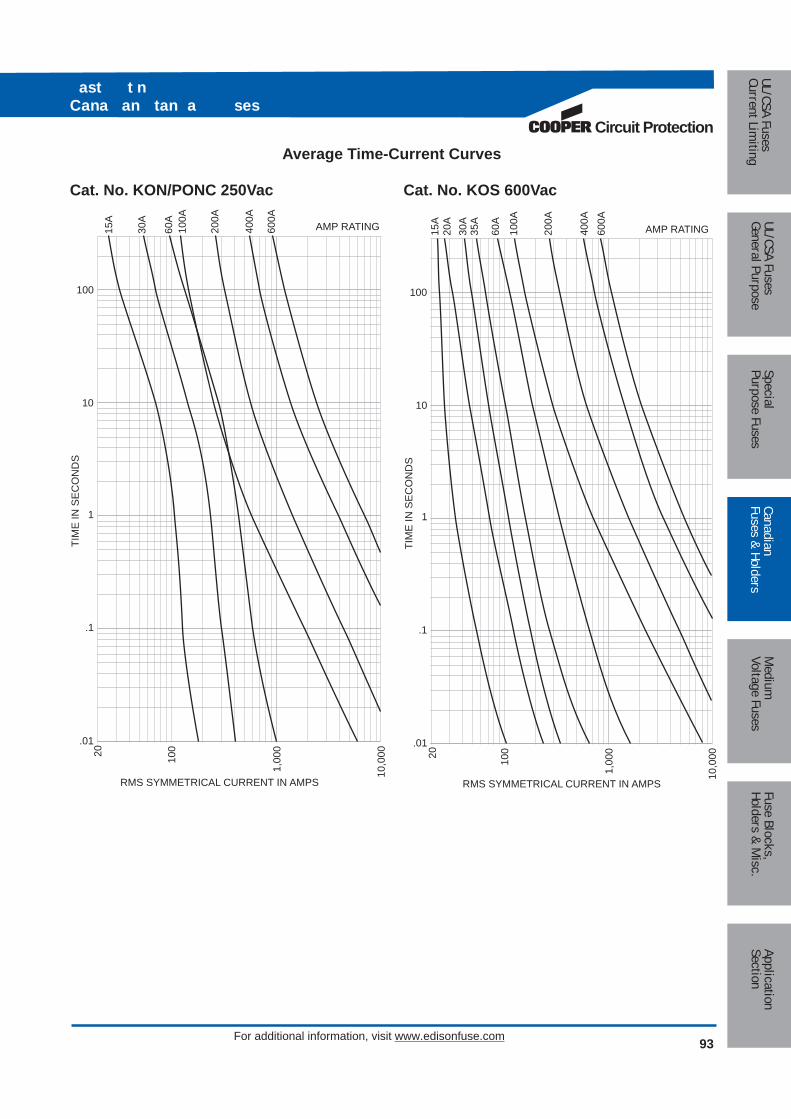
Circuit Protection
Medium
Voltage FusesUL/CSA FusesCurrent Lim
itingUL/CSA FusesGeneral Purpose
SpecialPurpose Fuses
CanadianFuses & Holders
ApplicationSection
Fuse Blocks,Holders & M
isc.
ast t nCana an tan a ses
For additional information, visit www.edisonfuse.com 93
Average Time-Current Curves
Cat. No. KON/PONC 250Vac Cat. No. KOS 600Vac
RMS SYMMETRICAL CURRENT IN AMPS
TIM
E IN
SE
CO
ND
S
100
1,00
0
10,0
00
100
10
1
.1
.01
20
60A
100A
200A
30A
400A
AMP RATING600A
15A
RMS SYMMETRICAL CURRENT IN AMPS
TIM
E IN
SE
CO
ND
S
100
1,00
0
10,0
00
100
10
1
.1
.01
20
60A
100A
200A
30A
400A
AMP RATING600A
15A
35A
20A
ast t nCana an tan a ses
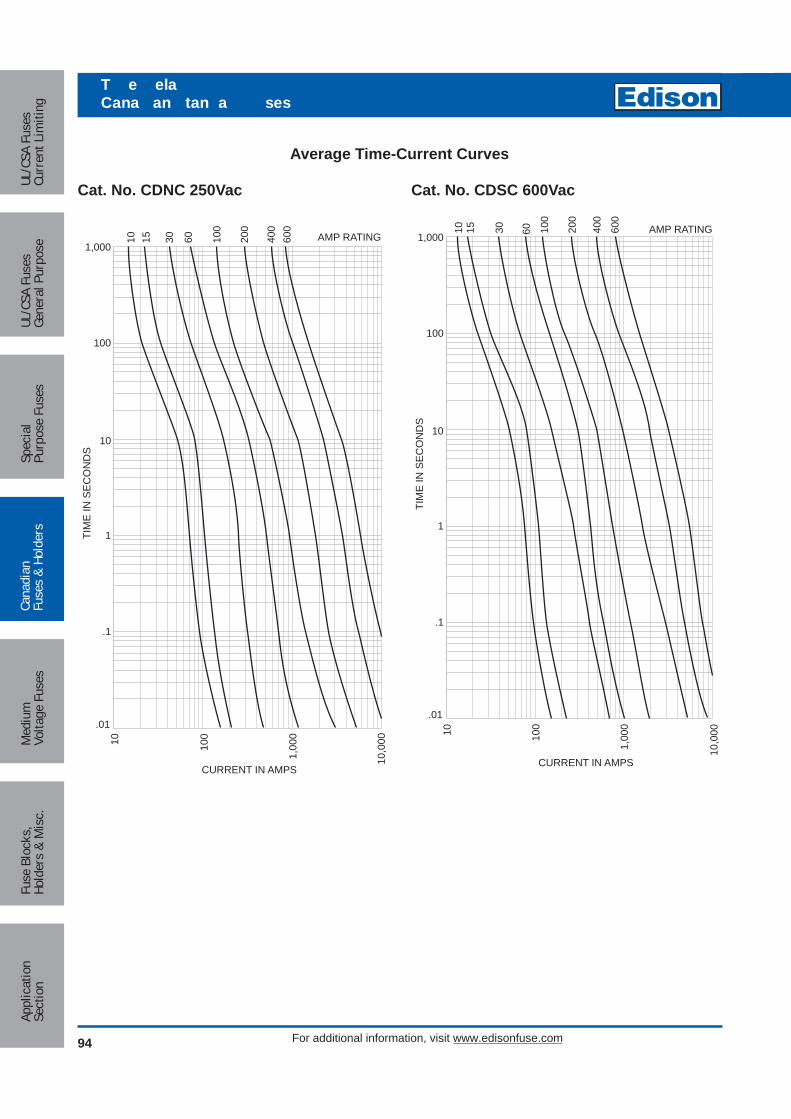
Med
ium
Volta
ge F
uses
UL/C
SA F
uses
Curr
ent L
imiti
ngUL
/CSA
Fus
esGe
nera
l Pur
pose
Spec
ial
Purp
ose
Fuse
sCa
nadi
anFu
ses
& Ho
lder
sAp
plic
atio
nSe
ctio
nFu
se B
lock
s,Ho
lder
s &
Mis
c.
For additional information, visit www.edisonfuse.com94
T e elaCana an tan a ses
Average Time-Current Curves
Cat. No. CDNC 250Vac Cat. No. CDSC 600Vac
10,0
00
1,00
0
10010
1,000
100
10
1
.1
CURRENT IN AMPS
TIM
E IN
SE
CO
ND
S
.01
30 60 100
200
400
600
AMP RATING10 15
10,0
00
1,00
0
10010
1,000
100
10
1
.1
CURRENT IN AMPS
TIM
E IN
SE
CO
ND
S
.01
30 60 100
200
400
600
AMP RATING10 15

Circuit Protection
Medium
Voltage FusesUL/CSA FusesCurrent Lim
itingUL/CSA FusesGeneral Purpose
SpecialPurpose Fuses
CanadianFuses & Holders
ApplicationSection
Fuse Blocks,Holders & M
isc.
For additional information, visit www.edisonfuse.com 95
Figure 1
C aste C se ol e s
FuseRating Details Reference Accommodated30 Amp 20BS For CM20CF30 Amp Back Stud 30BS For CM30CF60/100 Amp 60/100BS For CM60/100CFAll Ganging GLP For 3 Pole
Link KitAll 660V Neon NI-660 –
Indicator30 Amp Security 20LSC For CM20CF30 Amp Carrier 30LSC For CM30CF60/100 Amp with Clip. 60/100LSC For CM60/100CFAll Clip Only CMCS For all si es30 Amp 20CML For CM20CF30 Amp Solid Link 32CML For CM30CF60/100 Amp 63/100 CML For CM60/100CF
FuseRating Details Reference Accommodated
For30 Amp HRCI-CA CM20CF --CIF21
Applications30 Amp For CM30CF ---H07C60 Amp HRCII CM60CF ---KO7C100 Amp Applications CM100CF ---K07CR
Unique Cam ActionThe fuse carriers are fitted with a cam for ease of removalfrom the fuse bases allowing significantly improved contactpressure between fuse carrier and fuse base contacts, witha corresponding enhanced electrical performance level.This design overcomes a major problem of all existing deadfront style fuse holders manufactured worldwide, whichhave to compromise between difficulties of fuse carrierremoval from base and contact pressure achieved.
Lockable Safety CarriersA range of lockable safety carriers for the CAMaster fuseholder (Cat ref: LSC), are available. This distinct featureensures isolation can be achieved allowing maintenance tobe carried out in safety.
Fixing Torque and Cable Size
CAMaster Ratings
Range: 30 (miniature), 30, 60, and 100A, 600VacA range of fully shrouded HRC fuse holders having an advanced design. They incorporate a high level of innovation, withenhanced performance characteristics and comply with the requirements of: CSA C22.2 No. 39 as well as IEC 60269 andBS88 Standards.
Amps Mounting Edison Catalog NumbersFront CM20CF
30 Front/2-pole 2xCM20CF GLPBack CM20CF 2 off 20BSFront/Back CM20CF 1 off 20BSFront CM30CF
30 Back CM30CF 2 off 30BSFront/Back CM30CF 1 off 30BSFront CM60CF
60 Back CM60CF 2 of 60/100BSFront/Back CM60CF 1 of 60/100BSFront CM100CF
100* Back CM100CF 2 of 60/100BSFront/Back CM100CF 1 or 60/100BS
*Uses compact Edison fuses.
Catalog Numbers
Fuse Fixing Max CableRef Tightening Tor ues SizeCM20CF 1.5N m 2CM30CF 1.5N m 2CM60CF 2.0N m 2/0CM100CF 2.0N m 2/0
Accessories for CAMaster Units
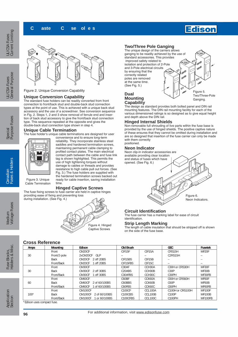
Med
ium
Volta
ge F
uses
UL/C
SA F
uses
Curr
ent L
imiti
ngUL
/CSA
Fus
esGe
nera
l Pur
pose
Spec
ial
Purp
ose
Fuse
sCa
nadi
anFu
ses
& Ho
lder
sAp
plic
atio
nSe
ctio
nFu
se B
lock
s,Ho
lder
s &
Mis
c.
For additional information, visit www.edisonfuse.com96
C aste C se ol e s
Unique Conversion CapabilityThe standard fuse holders can be readily converted from front connection to front/back stud and double-back stud connectiontypes at the point of use. This is achieved with a unique back studaccessory and the use of a screwdriver. See conversion sequencein Fig. 2. Steps 1, 2 and 3 show removal of ferrule end and inser-tion of back stud accessory to give the front/back stud connectiontype. This sequence repeated at the opposite end gives the double-back stud connection type shown in step 4.
Unique Cable TerminationThe fuse holder’s unique cable terminations are designed for user
convenience and to ensure long-term reliability. They incorporate stainless steelsaddles and hardened termination screws,maintaining permanent cable clamping toprofiled contact plates. The main electricalcontact path between the cable and fuse linktag is shown highlighted. This permits theuse of high tightening torques without damage to cables or threads and providesresistance to high cable pull out forces. (SeeFig. 3.) The fuse holders are supplied withthe hardened termination screws backed outready for cable insertion, saving installationtime.
Hinged Captive ScrewsThe fuse fixing screws to fuse carrier are held in captive hinges providing ease of fixing and preventing lossduring installation. (See Fig. 4.)
Figure 3. UniqueCable Termination
Figure 4. HingedCaptive Screws
Two/Three Pole GangingThe unique design of the carriers allows ganging to be readily achieved by the use of standard accessories. This providesimproved safety related to isolation and protection of 2-Pole and 3-Pole electrical circuits by ensuring that the correctly related poles are removed at the same time. (See Fig. 5.)
DualMountingCapabilityThe design as standard provides both bolted panel and DIN railmounting features. The DIN rail mounting facility for each of thevarious dimensioned ratings is so designed as to give equal heightand depth above the DIN rail.
Hinged Internal ShieldsNon-removable full shrouding of live parts within the fuse base isprovided by the use of hinged shields. The positive captive natureof these ensures that they cannot be omitted during installation andare so designed that insertion of the fuse carrier can only be madewith them correctly positioned.
Neon IndicatorNeon clip-in indicator accessories are available providing clear location and status of fuses which have opened. (See Fig. 6.)
Circuit IdentificationThe fuse carrier has a marking label for ease of circuit identification.
Strip Length MarkingThe length of cable insulation that should be stripped off is shownon the side of the fuse base.
Figure 6. Neon Indicators.
1 2 3 4
Figure 2. Unique Conversion Capability
Cross ReferenceAmps Mounting Edison Old Brush GEC Fusetek
Front CM20CF CIF15F CIF15A CRS15H MF20F30 Front/2-pole 2xCM20CF GLP – – C2RS15H –
Back CM20CF 2 off 20BS CIF15BS CIF15B – –Front/Back CM20CF 1 off 20BS CIF15FBS CIF15C – –Front CM30CF C30AF CCH30A C30H or CRS30H MF30F
30 Back CM30CF 2 off 30BS C20ABS CCH30B C30P MF30BFront/Back CM30CF 1 off 30BS C30AFBS CCH30C C30PH MF30FBFront CM60CF C60BF CCK60A C60H or CRS60H MF60F
60 Back CM60CF 2 of 60/100BS C60BBS CCK60B C60P MF60BFront/Back CM60CF 1 of 60/100BS C60FBS CCK60C C60PH MF60FBFront CM100CF C100CF CCL100A C100H or CRS100H MF100F
100* Back CM100CF 2 of 60/100BS C100CBS CCL100B C100P MF100BFront/Back CM100CF 1 or 60/100BS C100CFBS CCL100C C100PH MF100FB
*Edison uses compact fuse.
Figure 5. Two/Three-Pole Ganging.

Circuit Protection
Medium
Voltage FusesUL/CSA FusesCurrent Lim
itingUL/CSA FusesGeneral Purpose
SpecialPurpose Fuses
CanadianFuses & Holders
ApplicationSection
Fuse Blocks,Holders & M
isc.
For additional information, visit www.edisonfuse.com97
C aste C se ol eens ons
Standard Front Connected Unit Front/Back Stud and Double Back StudConnected Units
A
B
D
44CL OF DIN RAIL
CE
STR
IPS
TRIP
STR
IPS
TRIP
F
HG
øK
øJ
Rating Catalog Dimensions - in (mm)Amps Number Category A B C D E F G K30 CM20CF HRCI-CA 1.0 (25.4) 3.69 (93.7) 2.36 (60) 0.13 (3.2) 0.64 (17.5) 2.60 (66) 2.29 (58) 1.13 (28.6) 0.47 (11.9) M630 CM30CF HRCII-C 1.25 (31.8) 4.63 (117.5) 2.36 (60) 0.13 (3.2) 0.69 (17.5) 2.60 (66) 2.92 (74) 1.13 (28.6) 0.47 (11.9) M6 60 CM60CF HRCII-C 1.40 (35.6) 4.93 (125) 2.36 (60) 0.19 (4.75) 0.65 (16.4) 3.41 (86.5) 3.14 (79.8) 1.13 (28.6) 0.47 (11.9) M8100 CM100CF HRCII-MISC 1.40 (35.6) 4.93 (125) 2.36 (60) 0.19 (4.75) 0.65 (16.4) 3.41 (86.5) 3.14 (79.8) 1.13 (28.6) 0.47 (11.9) M8
Panel Drilling Plans, Viewed from Front of Panel
CL
CL
1.14"29.0mm
1.14"29.0mm
0.22"ø5.5mm
0.59"ø15.0mm
CM20CF
CL
CL
0.22"ø5.5mm
0.75"ø19mm
CM30CF
1.46"37.0mm
0.13"3.2mm
0.13"3.2mm
0.25"6.35mm
0.25"6.35mm
CL
CL
0.22"ø5.5mm
0.75"ø19mm
CM60 + 100CF
1.46"37.0mm
0.13"3.2mm
0.13"3.2mm
0.25"6.35mm
0.25"6.35mm
1.46"37.0mm
1.62"41.0mm
Dimensions - in (mm)

Med
ium
Volta
ge F
uses
UL/C
SA F
uses
Curr
ent L
imiti
ngUL
/CSA
Fus
esGe
nera
l Pur
pose
Spec
ial
Purp
ose
Fuse
sCa
nadi
anFu
ses
& Ho
lder
sAp
plic
atio
nSe
ctio
nFu
se B
lock
s,Ho
lder
s &
Mis
c.
For additional information, visit www.edisonfuse.com98
LOC C se ol e s
For use with RCI-CB FusesEdison Fuse
Rating Connection Catalog Numbers AccommodatedFront C30F
30 Amp Back C30BS CIF06Front-Back C30FBSFront C60F
60 Amp Back C60BS EKFront-Back C60FBS
DescriptionSAFEloc fuse holders provide a simple range designed toaccommodate the compact range of offset blade fuse toCSA C22.2 No. 106, HRCI-CB. The combination offerssignificant savings in volume and cost as well as a reductionin fitting time and power loss.
FeaturesThe fuse holders incorporate a unique slide/snap actioncarrier which eliminates the need for fuse carrier contacts.This provides positive, stress free fitting of fuse and locksthe fuse in position ensuring safe insertion and withdrawalfrom the base. The resulting direct contact between fuseblades and the plated base contacts provides lower wattsloss and increased reliability. The base contacts are fullyshrouded to protect personnel from direct contact electricshock. The shrouds utilize simple slide/snap action allowingaccess to the contact terminal screws. They are semi-captive within the base, reducing the risk of loss duringcabling. The fuse base, which consists of glass filled, highimpact resistant thermoplastic polyester, incorporates adirect 35mm DIN rail mounting facility as well as singlescrew fixing.
Tightening TorqueTo avoid a heat build up it is most important the cableterminal screws are screwed in tight and are holding thecable firmly. A tightening torque of 2.5 to 2.8 Newton meters(N•m) or 22 to 25lb-in is recommended.
Catalog Numbers
For use with HRCI-CB Fuses. Suitable for Bolted Panel Mounting or DIN-Rail Mounting.
SAFELOC fuse holders provide an easy method of protectinga wide range of electrical equipment such as lighting,heating, motor and control equipment circuits, and offersignificant savings on volume, cost, fitting time and powerloss.
Cross ReferenceAmps Mounting Edison GEC FUSETEK
Front C30F CSC30H MD30F30 Back C30BS CSC30P MD30B
Front/Back C30FBS – MD30FBFront C60F CSC60H –
60 Back C60BS – –Front/Back C60FBS – –

Circuit Protection
Medium
Voltage FusesUL/CSA FusesCurrent Lim
itingUL/CSA FusesGeneral Purpose
SpecialPurpose Fuses
CanadianFuses & Holders
ApplicationSection
Fuse Blocks,Holders & M
isc.
For additional information, visit www.edisonfuse.com 99
CatalogNumbers
C30F
CatalogNumbersC30BS
C30FBSC60BS
C60FBS
CatalogNumbers
C60F
F
øJ
øK
G
G/2
G/2
CCA
D H
EE
E
C
C
D
B
0.24
B 35mmDIN Rail
DIN Rail
Dimensions - in (mm)
Series Max.Amps Number Cable mm2 A B C D E F G K
30 C30 16 1.0 (25.4) 3.0 (76.2) 1.83 (46.5) 0.09 (2.3) 0.63 (16.0) 1.54 (39.2) 2.27 (57.7) 0.67 (17.0) 0.38 (9.7) M660 C60 35 1.15 (29.1) 3.55 (90.0) 2.18 (55.0) 0.13 (3.3) 0.70 (17.7) 1.54 (39.2) 2.68 (67.9) 0.69 (17.5) 0.43 (11.0) M8
0.09"2.3mm
0.09"2.3mm
*Hole for front connectedtypes when anti-roatation
pin is fitted.
0.51"ø13mm
0.22"ø5.5mm
*0.10"
ø2.5mm
0.63"ø16mm
0.22"ø5.5mm
*0.10"ø2.5mm0.79"
20.0mm2.27"
57.7mm 2.68"67.9mm
0.89"22.6mm
0.13"3.3mm
0.13"3.3mm
C30 C60
Dimensions - in (mm)
LOC C se ol e s

Med
ium
Volta
ge F
uses
UL/C
SA F
uses
Curr
ent L
imiti
ngUL
/CSA
Fus
esGe
nera
l Pur
pose
Spec
ial
Purp
ose
Fuse
sCa
nadi
anFu
ses
& Ho
lder
sAp
plic
atio
nSe
ctio
nFu
se B
lock
s,Ho
lder
s &
Mis
c.
For additional information, visit www.edisonfuse.com100
Medium voltage fuses for motor circuits offer the followinguser benefits:
• Performance complies with latest ANSI Standards
• Dramatic reduction in energy let-through
• Lower power dissipation
• Low arc voltage during operation
• Includes heavy duty striker to IEC 282-1
Advantages of Edison Motor FusesDuring the full voltage starting of motors the fuse elementsreach a considerably higher temperature than normallyoccurs under continuous operation. The resulting expansionand contraction of the fuse element can cause prematureoperation. The Edison motor circuit fuse incorporates provisions in the design of the element to minimize thiseffect and hence avoid the necessity of having to use amuch larger size of fuse.
Edison fuses operate very quickly on heavy fault currents.This results from the steepness of the time-current characteristic, which also facilitates coordination with theother components of the circuit.
Lower power dissipation helps to ensure low temperaturerise of, for example, multi-tier starters.
Switching (arc) voltages are appreciably less than permittedvalues and fall with lower values of system voltage. Thus,the 5.5kV fuses are equally suitable for use in 4.8kV,4.16kV and 2.4kV circuits.
The superior low-overcurrent breaking performance is ofadvantage whether or not the striker is used to open thecontactor.
“R” RatingThe R-Rated motor circuit fuses should be selected to coordinate with the motor and controller to provide short-circuit protection.
The actual “R” rating signifies a 20 second opening time at100 times the “R” rating of the fuse.
For example:
2R fuse opens in 20 seconds at 200A.
12R fuse opens in 20 seconds at 1200A.
Motor Starting ApplicationApplication ProcedureFor any motor the fuse current rating is determined by magnitude and duration of starting current, except in a fewsituations where the starting conditions are very light. Thefuse current rating should be selected as follows.
Direct On-Line StartingIn the absence of specific information the starting currentcan usually be taken to be six times the motor full load current. The starting time will depend on the type of drivebut will be approximately as follows:
Pump Motors - 6 seconds
Mill Motors - 10 to 15 seconds
Fan Motors - 60 seconds
These are average values and the appropriate figures forstarting current and starting time for the actual installationshould be obtained wherever possible. Multiply the startingcurrent by 1.6 and using this value of current and the starting time (it is recommended that a minimum time of 8seconds be adopted) plot this point on the minimum meltingtime-current characteristics of the fuses. The correct currentrating of fuse is then chosen as being the one immediatelyto the right of the point so plotted. The chosen fuse mustalso have a current rating of at least 1.3 times the full-loadcurrent of the associated motor.
The rating thus chosen will be adequate for normal applications where the associated motor is not started morethan twice in any given period of one hour. For applicationsinvolving more frequent starting duties, a greater deratingfactor must be applied as shown in the following table.
Derating Factor
The figures in the above table apply only when the Minimum Melting Time-Current Characteristic Curve is used.For applications involving more frequent starting duty than 16 times perhour or where unusual duty cycles are involved consult Edison CustomerSatisfaction for advice.Assisted StartingA similar method of fuse selection may be used as fordirect-on-line starting (see above) but it must be noted thatthe normal running current of the motor is likely to be closerin value to the nominal current rating of the fuse than fordirect-on-line applications.
The rating of fuse chosen will need to be appreciablygreater than the motor running current to allow for restrictedcooling inside control gear cubicles, particularly where multi-tier starters are involved. In case of doubt refer toEdison Customer Satisfaction for further guidance.
Maximum of starts per hour Derating factor2 1.64 1.78 2.016 2.2
ate e olta e sesfo oto C ts
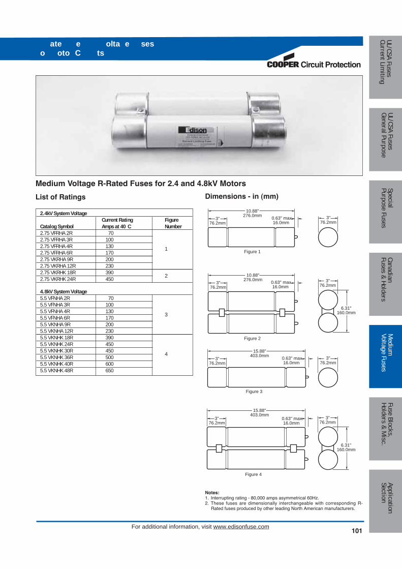
Circuit Protection
101
Medium
Voltage FusesUL/CSA FusesCurrent Lim
itingUL/CSA FusesGeneral Purpose
SpecialPurpose Fuses
CanadianFuses & Holders
ApplicationSection
Fuse Blocks,Holders & M
isc.
For additional information, visit www.edisonfuse.com
ate e olta e seso oto C ts
Notes:1. Interrupting rating - 80,000 amps asymmetrical 60Hz.2. These fuses are dimensionally interchangeable with corresponding R-
Rated fuses produced by other leading North American manufacturers.
List of Ratings
Medium Voltage R-Rated Fuses for 2.4 and 4.8kV Motors
Dimensions - in (mm)
0.63" max.16.0mm
10.88"276.0mm
3"76.2mm
Figure 1
0.63" max.16.0mm
15.88"403.0mm
3"76.2mm
Figure 3
Figure 4
6.31"160.0mm
3"76.2mm
Figure 2
0.63" max.16.0mm
10.88"276.0mm
3"76.2mm
0.63" max.16.0mm
15.88"403.0mm
3"76.2mm
3"76.2mm
3"76.2mm
6.31"160.0mm
3"76.2mm
2.4kV System VoltageCurrent Rating Figure
Catalog Symbol Amps at 40 C Number2.75 VFRHA 2R 702.75 VFRHA 3R 1002.75 VFRHA 4R 1302.75 VFRHA 6R 170
1
2.75 VKRHA 9R 2002.75 VKRHA 12R 2302.75 VKRHK 18R 3902.75 VKRHK 24R 450 2
4.8kV System Voltage5.5 VFNHA 2R 705.5 VFNHA 3R 1005.5 VFNHA 4R 1305.5 VFNHA 6R 170 3
5.5 VKNHA 9R 2005.5 VKNHA 12R 2305.5 VKNHK 18R 3905.5 VKNHK 24R 4505.5 VKNHK 30R 4505.5 VKNHK 36R 500 4
5.5 VKNHK 40R 6005.5 VKNHK 48R 650

102
Med
ium
Volta
ge F
uses
UL/C
SA F
uses
Curr
ent L
imiti
ngUL
/CSA
Fus
esGe
nera
l Pur
pose
Spec
ial
Purp
ose
Fuse
sCa
nadi
anFu
ses
& Ho
lder
sAp
plic
atio
nSe
ctio
nFu
se B
lock
s,Ho
lder
s &
Mis
c.
For additional information, visit www.edisonfuse.com
100,0
00
10,0
00
1,0
00
100
100
10
1
.1
RMS SYMMETRICAL CURRENT IN AMPS
TIM
E I
N S
EC
ON
DS
.01
4 6 9 12
18
24 "R"
RATING32 30
36
40
48
100,
000
10,0
00
1,00
0
100
100
10
1
.1
RMS SYMMETRICAL CURRENT IN AMPS
TIM
E IN
SE
CO
ND
S
.01
4 6 9 12 18 24"R"RATING32 30 36 48
40
Time-Current Characteristics for 5.5kV and 2.75kV FusesMinimum MeltTotal Clear
ate e olta e seso oto C ts

Circuit Protection
103
Medium
Voltage FusesUL/CSA FusesCurrent Lim
itingUL/CSA FusesGeneral Purpose
SpecialPurpose Fuses
CanadianFuses & Holders
ApplicationSection
Fuse Blocks,Holders & M
isc.
For additional information, visit www.edisonfuse.com
ate e olta e seso oto C ts
2.4kV 4.16kV 4.8kVFLA FUSE FLA FUSE FLA FUSE
p Amps R Amps Amps R Amps Amps R Amps75 17 2R 70 – – – – – –100 22 2R 70 – – – – – –125 28 3R 70 16 2R 70 – – –150 33 3R 100 19 2R 70 17 2R 70200 44 4R 130 26 3R 100 22 2R 70250 55 6R 170 32 3R 100 28 3R 100300 67 6R 170 38 4R 130 33 3R 100350 78 9R 170 45 4R 130 39 4R 130400 89 9R 200 45 4R 130 44 4R 130500 111 12R 230 64 6R 170 55 6R 170600 133 18R 390 77 9R 200 67 6R 170700 155 18R 390 90 9R 200 78 9R 200800 177 18R 390 102 9R 230 89 9R 200900 200 18R 390 115 12R 230 100 9R 2001000 222 24 450 128 18R 390 111 12R 2301100 244 24R 450 141 18R 390 122 12R 2301200 266 24R 450 154 18R 390 133 18R 3901400 311 30R 450 179 18R 390 155 18R 3901600 355 36R 500 205 18R 390 177 18R 3901800 399 40R 600 230 24R 450 200 18R 3901900 422 40R 600 243 24R 450 211 18R 3902000 444 40R 600 256 24R 450 222 24R 4502200 488 48R 650 282 30R 450 244 24R 4502400 – – – 307 30R 450 266 24R 4502600 – – – 333 36R 500 288 30R 4502800 – – – 358 36R 500 311 30R 4503000 – – – 384 36R 500 333 36R 5003500 – – – 448 40R 600 388 36R 5004000 – – – – – – 444 40R 6004500 – – – – – – 500 48R 650
Peak Let-Through Current Curve (5.5kV and 2.75kV Fuses)
101.1
100
10
1
.1
PROSPECTIVE CURRENT (SYM. RMS kA)
PE
AK
CU
RR
EN
T (k
A)
469121824
"R"
RATIN
G
32
30364048
Application for HV Motor Circuit FusesThe following table is a general guide only based on a number of assumptions regarding the motor duty application which are listed below. Contact EdisonCustomer Satisfaction for specific application information.The application tables are based on the following assumptions:
Contact Edison Customer Satisfaction for applications regarding other operating conditions.
Motor Efficiency ---------- 90% Run Up Time ------ 10 Secs.
Motor Power Factor ----- 0.9 Starting Method -- Full Voltage
Starting Current ---------- 6 x FLA Min. Fuse Size---- 1.3 x FLA
Starts/Hour ---------------- Max of 2/Hour

104
Med
ium
Volta
ge F
uses
UL/C
SA F
uses
Curr
ent L
imiti
ngUL
/CSA
Fus
esGe
nera
l Pur
pose
Spec
ial
Purp
ose
Fuse
sCa
nadi
anFu
ses
& Ho
lder
sAp
plic
atio
nSe
ctio
nFu
se B
lock
s,Ho
lder
s &
Mis
c.
For additional information, visit www.edisonfuse.com
E-Rated Power Fuses Having Full Range Clearing Capability for Medium VoltageTransformer Circuit Protection
Part Amp Length Dia. of ClipNumber Rating (In) (In) Barrels Center (In)MV055F1CAX5E 5E 15.75 2 1 12MV055F1CAX7E 7E 15.75 2 1 12MV055F1CAX10E 10E 15.75 2 1 12MV055F1CAX15E 15E 15.75 2 1 12MV055F1CAX20E 20E 15.75 2 1 12MV055F1CAX25E 25E 15.75 2 1 12MV055F1CAX30E 30E 15.75 2 1 12MV055F1CAX40E 40E 15.75 2 1 12MV055F1CAX50E 50E 15.75 2 1 12MV055F1CAX65E 65E 15.75 2 1 12MV055F1DAX10E 10E 15.75 3 1 12MV055F1DAX15E 15E 15.75 3 1 12MV055F1DAX20E 20E 15.75 3 1 12MV055F1DAX25E 25E 15.75 3 1 12MV055F1DAX30E 30E 15.75 3 1 12MV055F1DAX40E 40E 15.75 3 1 12MV055F1DAX50E 50E 15.75 3 1 12MV055F1DAX65E 65E 15.75 3 1 12MV055F1DAX80E 80E 15.75 3 1 12MV055F1DAX100E 100E 15.75 3 1 12MV055F1DAX125E 125E 15.75 3 1 12MV055F1DAX150E 150E 15.75 3 1 12MV055F1DAX175E 175E 15.75 3 1 12MV055F1DAX200E 200E 15.75 3 1 12MV055F2DAX250E 250E 15.75 3 2 12MV055F2DAX300E 300E 15.75 3 2 12MV055F2DAX350E 350E 15.75 3 2 12MV055F2DAX400E 400E 15.75 3 2 12
MV055 Specifications
E-Rated Medium Voltage Fuses
Meets E-Rating requirements of ANSI C37.46
Meets Full Range requirements of ANSI C37.40.
Voltage Rating: 5,500Vac
Interrupting Rating: 50kA Maximum Symmetrical Amps
Current Limiting
Benefits:
• Standard clip center lengths and barrel diameters.
• 100% tested for reliability.
• Suitable for indoor or outdoor usage.
• Full Range capability.
Applications:
• For transformer and feeder protection.
Recommended Fuseclips:
Refer to page 109 in this catalog.
ate e olta e ses
CROSS REFERENCENEW EDISON OLD EDISON GOULD (old new) WESTING OUSE GE (old new)MV055F1CAX — A550X – 1B/A055F1CORO — —MV055F1DAX 5.5FFNHA or K A550X – 1F/A055F1DORO 151D978G01 thru G08 9F60F Dxxx/9F62DCBxxxMV055F1DAX 5.5BFNHA — 5HLExxxE – 1 —MV055F2DAX 5.5BFNHK A550X – 1/A055F2DORO 151D978G11 thru G13 9F60GHC (250-400)

Circuit Protection
105
Medium
Voltage FusesUL/CSA FusesCurrent Lim
itingUL/CSA FusesGeneral Purpose
SpecialPurpose Fuses
CanadianFuses & Holders
ApplicationSection
Fuse Blocks,Holders & M
isc.
For additional information, visit www.edisonfuse.com
ate e olta e ses
E-Rated Medium Voltage Fuses for Transformer and Feeder Protection
TIM
E IN
SE
CO
ND
S
100
10
1
.1
.01
30A
25A
20A
15A
10A
7A5A AMP RATING
1000
700010010
CURRENT IN AMPS
40A
50A
65A
TIM
E IN
SE
CO
ND
S
AMP RATING
1000
700010010
CURRENT IN AMPS
65A
50A
40A
30A
25A
20A
15A
10A
7A5A
100
10
1
.1
.01
Time-Current Characteristics–Min. Melt Time-Current Characteristics–Total Clear
Dimensions - in
MV055F1CAX
2.03"0.63"0.38"
1.25" 1.25"
15.75"14.74"
Position of Open FuseIndicator After Operating
2.00"
12.00"Clip Center

106
Med
ium
Volta
ge F
uses
UL/C
SA F
uses
Curr
ent L
imiti
ngUL
/CSA
Fus
esGe
nera
l Pur
pose
Spec
ial
Purp
ose
Fuse
sCa
nadi
anFu
ses
& Ho
lder
sAp
plic
atio
nSe
ctio
nFu
se B
lock
s,Ho
lder
s &
Mis
c.
For additional information, visit www.edisonfuse.com
E-Rated Medium Voltage Fuses for Transformer and Feeder ProtectionTime-Current Characteristics–Min. Melt Time-Current Characteristics–Total Clear
Dimensions - in
MV055F1DAX
TIM
E IN
SEC
ONDS
100
10
1
.1
.01
100A
80A
65A
50A
40A0A25A
AMP RATING
1000 00
0
10010
CURRENT IN AMPS
20A
15A
10A
TIM
E IN
SE
CO
ND
S
100
10
1
.1
.01
100A
80A
65A
50A
40A
30A
25A
AMP RATING
1000
700010010
CURRENT IN AMPS
20A
15A
10A
2.40"0.63"0.38"
1.25"
3.00"
12.00"Clip Center
1.25"
15.75"14.74"
Position of Open FuseIndicator After Operating
ate e olta e ses
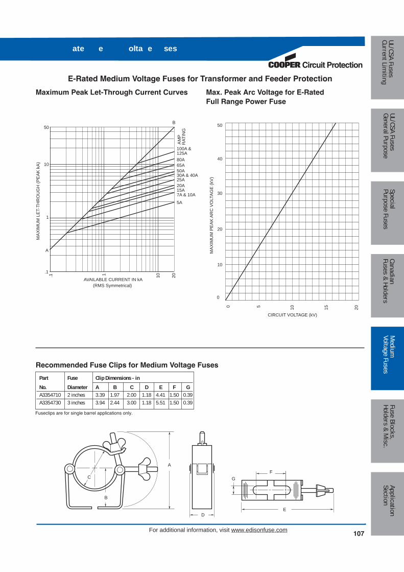
Circuit Protection
107
Medium
Voltage FusesUL/CSA FusesCurrent Lim
itingUL/CSA FusesGeneral Purpose
SpecialPurpose Fuses
CanadianFuses & Holders
ApplicationSection
Fuse Blocks,Holders & M
isc.
For additional information, visit www.edisonfuse.com
ate e olta e ses
E-Rated Medium Voltage Fuses for Transformer and Feeder Protection
Maximum Peak Let-Through Current Curves Max. Peak Arc Voltage for E-Rated Full Range Power Fuse
AM
PR
ATIN
G
100A &125A
MA
XIM
UM
LE
T-TH
RO
UG
H (P
EA
K k
A)
.1 1 10 20
50
10
1
.1
AVAILABLE CURRENT IN kA(RMS Symmetrical)
80A65A50A30A & 40A25A20A15A7A & 10A
5A
B
A MA
XIM
UM
PE
AK
AR
C V
OLT
AG
E (k
V)
50
40
CIRCUIT VOLTAGE (kV)
30
20
10
0
0 5 10 15 20
C
A
B
D
G
E
F
Recommended Fuse Clips for Medium Voltage Fuses
Fuseclips are for single barrel applications only.
Part Fuse Clip Dimensions - inNo. Diameter A B C D E F GA3354710 2 inches 3.39 1.97 2.00 1.18 4.41 1.50 0.39A3354730 3 inches 3.94 2.44 3.00 1.18 5.51 1.50 0.39

108
Med
ium
Volta
ge F
uses
UL/C
SA F
uses
Curr
ent L
imiti
ngUL
/CSA
Fus
esGe
nera
l Pur
pose
Spec
ial
Purp
ose
Fuse
sCa
nadi
anFu
ses
& Ho
lder
sAp
plic
atio
nSe
ctio
nFu
se B
lock
s,Ho
lder
s &
Mis
c.
For additional information, visit www.edisonfuse.com
E-Rated Power Fuses Having Full Range or Back-up Clearing Capability for MediumVoltage Transformer Circuit Protection
Part Amp Length Dia. of ClipNumber Rating (In) (In) Barrels Center (In)8.25FFNHA20E 20E 15.88 3 1 128.25FFNHA25E 25E 15.88 3 1 128.25FFNHA30E 30E 15.88 3 1 128.25FFNHA40E 40E 15.88 3 1 128.25FFNHA50E 50E 15.88 3 1 128.25FFNHA65E 65E 15.88 3 1 128.25FFNHA75E 75E 15.88 3 1 128.25FFNHK100E 100E 15.88 3 2 128.25FFNHK150E 150E 15.88 3 2 128.25BFNHA80* 80A 15.88 3 1 128.25BFNHA100* 100A 15.88 3 1 128.25BFNHK150* 150A 15.88 3 2 128.25BKNHK200* 200A 15.88 3 2 12
8.25FFNH Specifications
E-Rated Medium Voltage Fuses
Meets E-Rating requirements of ANSI C37.46
Meets Full Range requirements of ANSI C37.40
8.25BFNH Specifications
Back-up Medium Voltage FusesMeets Back-up requirements of ANSI C37.40
Voltage Rating: 8250Vac
Interrupting Rating: 80kA Max. Sym. Amps
Current Limiting
Low power dissipation
Low arc voltage during operation
Benefits:
• Standard clip center lengths and barrel diameters.
• Standard blown fuse striker pin may be used for indication or tripping purposes.
• 100% tested for reliability.
• Suitable for indoor or outdoor usage.
Applications:
• For transformer and feeder protection.
Recommended Fuse Clips:
Refer to page 109 in this catalog.
*Back-up protection only.
ate e olta e ses
CROSS REFERENCEEDISON GOULD WESTING OUSE GE (old new)8.25FFNHA A825X (amp)E-1 677C573Gxx 6193481Gxx/9F60F E (amp)8.25FFNHK A825X150–200E-1 — 9F60H E1508.25BKNHK200 A825X200E-1 — 9F60H E200
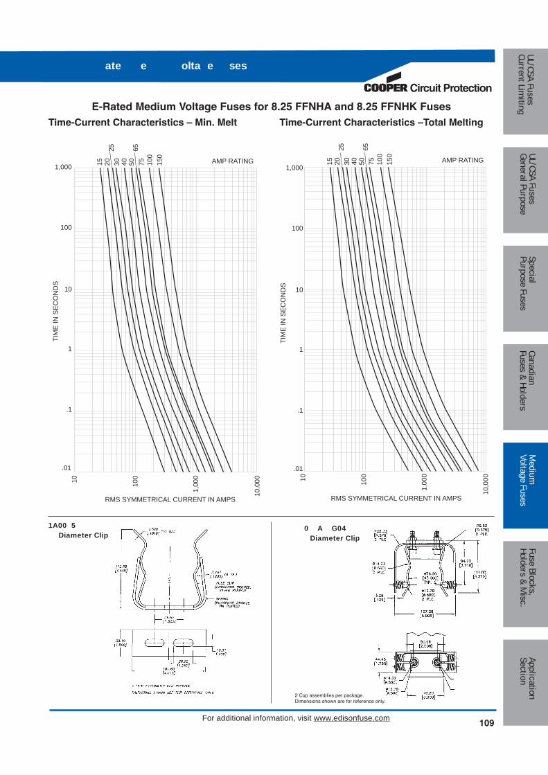
Circuit Protection
109
Medium
Voltage FusesUL/CSA FusesCurrent Lim
itingUL/CSA FusesGeneral Purpose
SpecialPurpose Fuses
CanadianFuses & Holders
ApplicationSection
Fuse Blocks,Holders & M
isc.
For additional information, visit www.edisonfuse.com
ate e olta e ses
10,0
00
1,00
0
10010
1,000
100
10
.1
RMS SYMMETRICAL CURRENT IN AMPS
TIM
E IN
SE
CO
ND
S
.01
140 50
6575 10
015
0
AMP RATING3025
2015
10,0
00
1,00
0
10010
1,000
100
10
1
.1
RMS SYMMETRICAL CURRENT IN AMPS
TIM
E IN
SE
CO
ND
S
.01
40 5065
75 100
150
AMP RATING3025
2015E-Rated Medium Voltage Fuses for 8.25 FFNHA and 8.25 FFNHK Fuses
Time-Current Characteristics – Min. Melt Time-Current Characteristics –Total Melting
1A00 5 Diameter Clip
0 A G04 Diameter Clip
2 Cup assemblies per package.Dimensions shown are for reference only.

110
Med
ium
Volta
ge F
uses
UL/C
SA F
uses
Curr
ent L
imiti
ngUL
/CSA
Fus
esGe
nera
l Pur
pose
Spec
ial
Purp
ose
Fuse
sCa
nadi
anFu
ses
& Ho
lder
sAp
plic
atio
nSe
ctio
nFu
se B
lock
s,Ho
lder
s &
Mis
c.
For additional information, visit www.edisonfuse.com
Back-up Medium Voltage Fuses for 8.25 BFNHA, 8.25 BFHNK, and 8.25 BKNHK FusesTime-Current Characteristics– Min. Melt Time-Current Characteristics–Max. Clear
10,0
00
1,00
0
10010
1,000
100
10
1
.1
RMS SYMMETRICAL CURRENT IN AMPS
TIM
E IN
SE
CO
ND
S
.01
100
150
200 AMP RATING80
10,0
00
1,00
0
10010
1,000
100
10
1
.1
RMS SYMMETRICAL CURRENT IN AMPS
TIM
E IN
SE
CO
ND
S
.01
100
150
200 AMP RATING80
ate e olta e ses

Circuit Protection
111
Medium
Voltage FusesUL/CSA FusesCurrent Lim
itingUL/CSA FusesGeneral Purpose
SpecialPurpose Fuses
CanadianFuses & Holders
ApplicationSection
Fuse Blocks,Holders & M
isc.
For additional information, visit www.edisonfuse.com
a e olta e ses
E-Rated Power Fuses Having Full Range Clearing Capability for Medium VoltageTransformer Circuit Protection
Part Amp Length Dia. of ClipNumber Rating (In) (In) Barrels Center (In)MV155F1CBX5E 5E 18.75 2 1 15MV155F1CBX7E 7E 18.75 2 1 15MV155F1CBX10E 10E 18.75 2 1 15MV155F1CBX15E 15E 18.75 2 1 15MV155F1CBX20E 20E 18.75 2 1 15MV155F1CBX25E 25E 18.75 2 1 15MV155F1CBX30E 30E 18.75 2 1 15MV155F1DBX10E 10E 18.75 3 1 15MV155F1DBX15E 15E 18.75 3 1 15MV155F1DBX20E 20E 18.75 3 1 15MV155F1DBX25E 25E 18.75 3 1 15MV155F1DBX30E 30E 18.75 3 1 15MV155F1DBX40E 40E 18.75 3 1 15MV155F1DBX50E 50E 18.75 3 1 15MV155F1DBX65E 65E 18.75 3 1 15MV155F1DBX80E 80E 18.75 3 1 15MV155F1DBX100E 100E 18.75 3 1 15MV155F2DBX125E 125E 18.75 3 2 15MV155F2DBX150E 150E 18.75 3 2 15MV155F2DBX175E 175E 18.75 3 2 15MV155F2DBX200E 200E 18.75 3 2 15MV155F1DCX65E 65E 21.75 3 1 18MV155F1DCX80E 80E 21.75 3 1 18MV155F1DCX100E 100E 21.75 3 1 18MV155F2DCX125E 125E 21.75 3 2 18MV155F2DCX150E 150E 21.75 3 2 18MV155F2DCX175E 175E 21.75 3 2 18MV155F2DCX200E 200E 21.75 3 2 18
MV155 Specifications
E-Rated Medium Voltage Fuses
Meets E-Rating requirements of ANSI C37.46
Meets Full Range requirements of ANSI C37.40.
Voltage Rating: 15,500Vac
Interrupting Rating: 50kA Maximum Symmetrical Amps
Current Limiting
Benefits:
• Standard clip center lengths and barrel diameters.
• 100% tested for reliability.
• Suitable for indoor or outdoor usage.
• Full Range capability.
Applications:
• For transformer and feeder protection.
Recommended Fuseclips:
Refer to page 114 in this catalog.
CROSS REFERENCENEW EDISON OLD EDISON GOULD (old new) WESTING OUSE GE (old new)MV155F1CBX — A1550X – 1B/A155F1CORO — —MV155F1DBX 15.5FFVHA A1550X – 1F/A155F1DORO (10-50E) 15HLE–xxxE 9F60FMH/9F62DDDMV155F2DBX 15.5FFVHK — — —MV155F1DCX — A1550X – 1D/A155F1DORO (65-100E) — —MV155F2DCX — A1550X – 1D/A155F2DORO (125-200E) — —
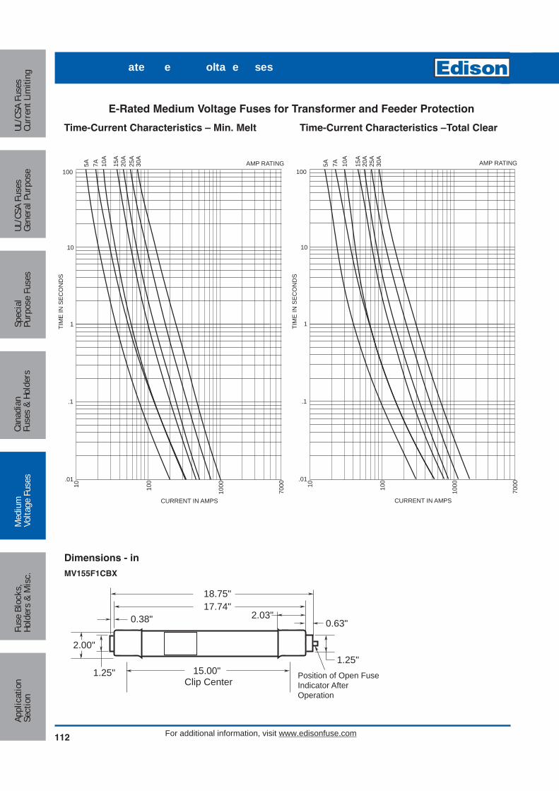
112
Med
ium
Volta
ge F
uses
UL/C
SA F
uses
Curr
ent L
imiti
ngUL
/CSA
Fus
esGe
nera
l Pur
pose
Spec
ial
Purp
ose
Fuse
sCa
nadi
anFu
ses
& Ho
lder
sAp
plic
atio
nSe
ctio
nFu
se B
lock
s,Ho
lder
s &
Mis
c.
For additional information, visit www.edisonfuse.com
E-Rated Medium Voltage Fuses for Transformer and Feeder Protection
TIM
E IN
SE
CO
ND
S
100
10
1
.1
.01
30A
25A
20A
15A
10A
7A5A AMP RATING
1000
700010010
CURRENT IN AMPS
TIM
E IN
SE
CO
ND
S
AMP RATING
1000
700010010
CURRENT IN AMPS
30A
25A
20A
15A
10A
7A5A
100
10
1
.1
.01
Time-Current Characteristics – Min. Melt Time-Current Characteristics –Total Clear
Dimensions - in
MV155F1CBX
17.74"2.03"
0.63"0.38"
1.25"1.25"
18.75"
Position of Open FuseIndicator AfterOperation
2.00"
15.00"Clip Center
ate e olta e ses

Circuit Protection
113
Medium
Voltage FusesUL/CSA FusesCurrent Lim
itingUL/CSA FusesGeneral Purpose
SpecialPurpose Fuses
CanadianFuses & Holders
ApplicationSection
Fuse Blocks,Holders & M
isc.
For additional information, visit www.edisonfuse.com
ate e olta e ses
E-Rated Medium Voltage Fuses for Transformer and Feeder ProtectionTime-Current Characteristics – Min. Melt Time-Current Characteristics –Total Clear
Dimensions - in
MV155F1DBX
TIM
E IN
SE
CO
ND
S
100
10
1
.1
.01
100A
80A
65A
50A
40A
30A
25A AMP RATING
1000
700010010
CURRENT IN AMPS
20A
15A
10A
TIM
E IN
SE
CO
ND
S
100
10
1
.1
.01
100A
80A
65A
50A
40A
30A
25A AMP RATING
1000
700010010
CURRENT IN AMPS
20A
15A
10A
17.74"2.40"
0.63"0.38"
1.25"
3.00"
15.00"Clip Center
1.25"
18.75"
Position of Open FuseIndicator AfterOperating
21.75"20.74"
2.40"0.63"
1.25"3.38"
0.38"
1.25"
3.00"
18.00"Clip Center
Position of Open FuseIndicator AfterOperating
MV155F1DCX

114
Med
ium
Volta
ge F
uses
UL/C
SA F
uses
Curr
ent L
imiti
ngUL
/CSA
Fus
esGe
nera
l Pur
pose
Spec
ial
Purp
ose
Fuse
sCa
nadi
anFu
ses
& Ho
lder
sAp
plic
atio
nSe
ctio
nFu
se B
lock
s,Ho
lder
s &
Mis
c.
For additional information, visit www.edisonfuse.com
E-Rated Medium Voltage Fuses for Transformer and Feeder ProtectionMax. Peak Let-through Current Curves Maximum Peak Arc Voltage for E-Rated
Full Range Power Fuse
AM
PR
ATIN
G
100A &125A
MA
XIM
UM
LE
T-TH
RO
UG
H (
PE
AK
kA
)
.1 1 10 20
50
10
1
.1
AVAILABLE CURRENT IN kA(RMS Symmetrical)
80A65A50A30A & 40A25A20A15A7A & 10A
5A
B
A MA
XIM
UM
PE
AK
AR
C V
OLT
AG
E (k
V)
50
40
CIRCUIT VOLTAGE (kV)
30
20
10
0
0 5 10 15 20
C
A
B
D
G
E
F
Recommended Fuse Clips for Medium Voltage Fuses
Fuseclips are for single barrel applications only.
Part Fuse Clip Dimensions - inNo. Diameter A B C D E F GA3354710 2 inches 3.39 1.97 2.00 1.18 4.41 1.50 0.39A3354730 3 inches 3.94 2.44 3.00 1.18 5.51 1.50 0.39
ate e olta e ses

Circuit Protection
115
Medium
Voltage FusesUL/CSA FusesCurrent Lim
itingUL/CSA FusesGeneral Purpose
SpecialPurpose Fuses
CanadianFuses & Holders
ApplicationSection
Fuse Blocks,Holders & M
isc.
For additional information, visit www.edisonfuse.com
otent al T ansfo e ses
Catalog Dimensions - inches (Figure 1)kV Number Amp Ratings Type Length Diameter IR3.6 3.6ABWNA(amp) 3.15, 6.3 AB 5.6 13.6 3.6ABCNA(amp) 3.15, 6.3, 10 AB 7.69 15.5 5.5ABWNA(amp) 0.5E, 1.0E, 2.0E, 3.0E, 5.0E AB 5.6 15.5 5.5AMWNA(amp) 0.5E, 1.0E, 2.0E, 3.0E, 4.0E, 5.0E AM 5.6 0.817.2 7.2ABWNA(amp) 3.15, 6.3 AB 5.6 17.2 7.2ABCNA(amp) 3.15, 6.3 AB 7.69 1 50kA12.0 12ABCNA(amp) 3.15 AB 7.69 115.5 15.5ABFNA(amp) 3.15 AB 10.00 117.5 17.5ABGNA(amp) 3.15 AB 14.13 124.0 24ABGNA(amp) 3.15 AB 14.13 136.0* 36ABGNA(amp) 3.15 AB 14.13 1
Catalog Dimensions - inches (Figure 2)kV Number Amp Ratings Type Length Diameter IR3.6 3.6CAV(amp) 2 8CAV 8.665.5 5.5CAV(amp) 15E 7CAV 7.3755.5 5.5CAVH(amp) 0.5E, 1E, 2E 7CAVH 7.3757.2 7.2CAV(amp) 2, 4, 6, 10 8CAV 8.6612 12CAV(amp) 2 8CAV 8.6615.5 15.5CAV(amp) 0.5E, 1E, 2E, 3E, 7E 12CAV 12.87 1.63 40kA15.5 15.5CAVH(amp) 0.5E, 1E, 2E 12CAVH 12.8717.5 17.5CAV(amp) 2, 4, 6, 10 8CAV 8.6624 24CAV(amp) 2, 3, 4 13CAV 13.3936 36CAV(amp) 2, 4 17CAV 17.3238 38CAV(amp) 4E 17CAV 17.3238 38CAVH(amp) 0.5E, 1E, 2E 17CAV 17.32
AB & AM Series Fuses for Potential Transformers
These are a range of fuses with low current rating, for usewith voltage transformers or operating transformers toprovide isolation of the associated system in the event offaults in the transformer circuit.
Advantages of Edison Potential Transformer FusesMost fuses have two elements in parallel, ensuringsatisfactory operation at much smaller values of overcurrentthan is possible with single element fuse.
The elements are wound on a ceramic former, thus ensur-ing correct spacing of the elements from the body wall andfrom each other and hence giving assurance of correctoperation in service.
Switching (arc) voltages comply with the IEC282-1.
Application Notes
1. In order to minimize the risk of deterioration of the finefuse elements caused by corona, it is desirable to mountthe fuses so that grounded metal is not in the immediatevicinity of the part of the barrel between the ferrules.
2. It is recommended that all three fuses are replaced whenthe fuse in one or two phases has operated unless it isdefinitely known that no overcurrent has passed throughthe unopened fuses.
*For clean indoor applications only.
CAV Series Fuses for Potential Transformers

116
Med
ium
Volta
ge F
uses
UL/C
SA F
uses
Curr
ent L
imiti
ngUL
/CSA
Fus
esGe
nera
l Pur
pose
Spec
ial
Purp
ose
Fuse
sCa
nadi
anFu
ses
& Ho
lder
sAp
plic
atio
nSe
ctio
nFu
se B
lock
s,Ho
lder
s &
Mis
c.
For additional information, visit www.edisonfuse.com
1.18"30.20mm
See Table For Length
0.63" (15.9mm) For AMWNA 1.26" (32.1mm) For All Others
See TableFor Diameter
Figure 1
Figure 2
See TableFor Diameter
See Table For Length
(Type AB & AM)
(Type CAV)
0.5"12.7mm
0.21"5.3mmø
0.34"8.6mm0.68"
17.3mm
1"25.4mm
1.37"34.8mm
1
0.5E
1E
2E
3E
4E
5E
10080605040
30
20
108
54
3
2
1.8.6.5.4
.3
.2
.1.08.06.05.04
.03
.02
.01
2 3 4 5 6 8 10 200
0.5 20 30 40 50 60 80 100
TIME
IN S
EC
ON
DS
RMS SYMMETRICAL CURRENT IN AMPS
Time-Current Curves
10080605040
30
20
108
54
3
2
1.8.6.5.4
.3
.2
.1.08.06.05.04
.03
.02
.01
2 3 4 5 6 8 10 200
0.5 20 30 40 50 60 80 100
TIME
IN S
EC
ON
DS
RMS SYMMETRICAL CURRENT IN AMPS
0.5E
1E
2E
3E
5E
Part No. A3354705For 1” diameter potential transformer fuses.
Dimensions - in (mm) Fuseclips
5.5kV ABWNA5.5kV AMWNA
otent al T ansfo e ses

Circuit Protection
117
Medium
Voltage FusesUL/CSA FusesCurrent Lim
itingUL/CSA FusesGeneral Purpose
SpecialPurpose Fuses
CanadianFuses & Holders
ApplicationSection
Fuse Blocks,Holders & M
isc.
For additional information, visit www.edisonfuse.com
olta e st b t on ses
For Diameter and Length Dimensions See Table Above
1.77"45.0mm
Dia
met
er
0.59"15.0mm
Striker InOperated Position
Length 1.34"34.0mm
1.02"26.0mm
Dimensions - Inches (mm)
DIN Dimension Fuses To SpecificationDIN 43.625This product group covers current limiting fuses with dimensions to DIN 43.625 and performance in compliancewith IEC 282-1.
Advantages of Edison High Voltage Current - LimitingFusesThe low power dissipation of Edison fuses ensures lowtemperature rise of switchgear in which they are incorporated.
The elements use the ‘M’ (metallurgical) effect, similar tothat used in low voltage fuses. This ensures that, withmelting on long time overloads, excessive temperatures arenot reached and damage to switchgear components, suchas epoxy encapsulating enclosures, is thus prevented.Fuses that do not employ this feature are not only hotterrunning by comparison but also usually need to employ ahigher current rating of fuse for the same service; thus anEdison 40A fuse is equivalent in terms of thermal
performance to many other types of 63A rating.
Edison fuses exhibit considerable limitation of current andI2t under short-circuit conditions. The stress on circuit components is thereby minimized and the reduction ofenergy release at the fault reduces fire risks.
Switching (arc) voltages are appreciably less than permitted values and fall with lower values of recovery voltage. The use of, for example, 12kV fuse on 6/7.2kVsystems is therefore permissible.
Striker CharacteristicsThe spring operated striker pin has a travel and energy output in compliance with the requirements of DIN 43625and IEC 282-1.
Recommended Fuse Clipss:Refer to page 121 in this catalog.
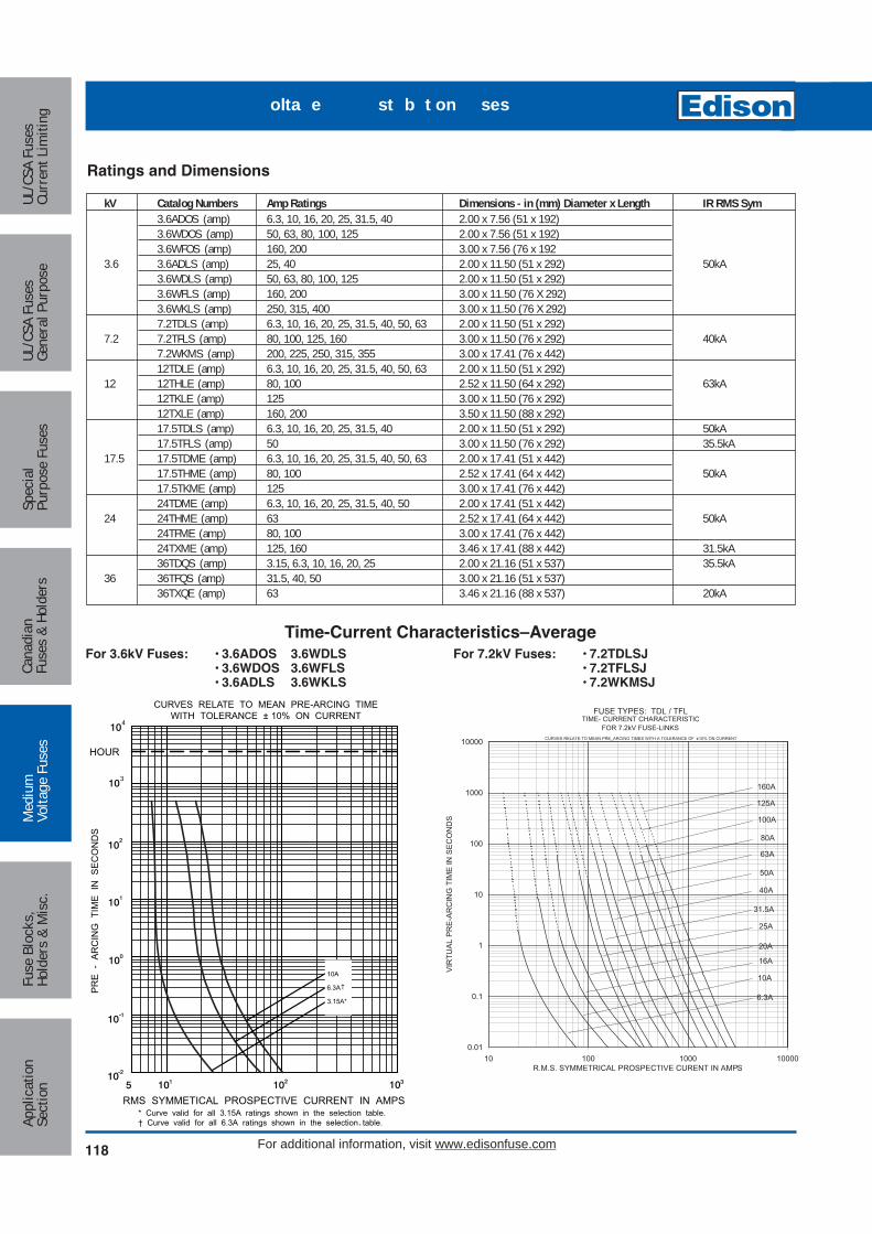
118
Med
ium
Volta
ge F
uses
UL/C
SA F
uses
Curr
ent L
imiti
ngUL
/CSA
Fus
esGe
nera
l Pur
pose
Spec
ial
Purp
ose
Fuse
sCa
nadi
anFu
ses
& Ho
lder
sAp
plic
atio
nSe
ctio
nFu
se B
lock
s,Ho
lder
s &
Mis
c.
For additional information, visit www.edisonfuse.com
kV Catalog Numbers Amp Ratings Dimensions - in (mm) Diameter x Length IR RMS Sym3.6ADOS (amp) 6.3, 10, 16, 20, 25, 31.5, 40 2.00 x 7.56 (51 x 192)3.6WDOS (amp) 50, 63, 80, 100, 125 2.00 x 7.56 (51 x 192)3.6WFOS (amp) 160, 200 3.00 x 7.56 (76 x 192
3.6 3.6ADLS (amp) 25, 40 2.00 x 11.50 (51 x 292) 50kA3.6WDLS (amp) 50, 63, 80, 100, 125 2.00 x 11.50 (51 x 292)3.6WFLS (amp) 160, 200 3.00 x 11.50 (76 X 292)3.6WKLS (amp) 250, 315, 400 3.00 x 11.50 (76 X 292)7.2TDLS (amp) 6.3, 10, 16, 20, 25, 31.5, 40, 50, 63 2.00 x 11.50 (51 x 292)
7.2 7.2TFLS (amp) 80, 100, 125, 160 3.00 x 11.50 (76 x 292) 40kA7.2WKMS (amp) 200, 225, 250, 315, 355 3.00 x 17.41 (76 x 442)12TDLE (amp) 6.3, 10, 16, 20, 25, 31.5, 40, 50, 63 2.00 x 11.50 (51 x 292)
12 12THLE (amp) 80, 100 2.52 x 11.50 (64 x 292) 63kA12TKLE (amp) 125 3.00 x 11.50 (76 x 292)12TXLE (amp) 160, 200 3.50 x 11.50 (88 x 292)17.5TDLS (amp) 6.3, 10, 16, 20, 25, 31.5, 40 2.00 x 11.50 (51 x 292) 50kA17.5TFLS (amp) 50 3.00 x 11.50 (76 x 292) 35.5kA
17.5 17.5TDME (amp) 6.3, 10, 16, 20, 25, 31.5, 40, 50, 63 2.00 x 17.41 (51 x 442)17.5THME (amp) 80, 100 2.52 x 17.41 (64 x 442) 50kA17.5TKME (amp) 125 3.00 x 17.41 (76 x 442)24TDME (amp) 6.3, 10, 16, 20, 25, 31.5, 40, 50 2.00 x 17.41 (51 x 442)
24 24THME (amp) 63 2.52 x 17.41 (64 x 442) 50kA24TFME (amp) 80, 100 3.00 x 17.41 (76 x 442)24TXME (amp) 125, 160 3.46 x 17.41 (88 x 442) 31.5kA36TDQS (amp) 3.15, 6.3, 10, 16, 20, 25 2.00 x 21.16 (51 x 537) 35.5kA
36 36TFQS (amp) 31.5, 40, 50 3.00 x 21.16 (51 x 537)36TXQE (amp) 63 3.46 x 21.16 (88 x 537) 20kA
Ratings and Dimensions
For 7.2kV Fuses: • 7.2TDLSJ• 7.2TFLSJ• 7.2WKMSJ
For 3.6kV Fuses: • 3.6ADOS 3.6WDLS• 3.6WDOS 3.6WFLS• 3.6ADLS 3.6WKLS
0.01
0.1
1
10
100
1000
10000
10 100 1000 10000R.M.S. SYMMETRICAL PROSPECTIVE CURENT IN AMPS
VIR
TUA
L P
RE
-AR
CIN
G T
IME
IN S
EC
ON
DS
TIME- CURRENT CHARACTERISTICFOR 7.2kV FUSE-LINKS
FUSE TYPES: TDL / TFL
CURVES RELATE TO MEAN PRE_ARCING TIMES WITH A TOLERANCE OF ±10% ON CURRENT
160A
125A
100A
80A
63A
50A
40A
31.5A
25A
20A
16A
10A
6.3A
* Curve valid for all 3.15A ratings shown in the selection table.† Curve valid for all 6.3A ratings shown in the selection table.
HOUR
10A
6.3A
3.15A*
3
4
PR
E -
AR
CIN
G T
IME
IN
SE
CO
ND
S
CURVES RELATE TO MEAN PRE-ARCING TIMEWITH TOLERANCE ± 10% ON CURRENT
RMS SYMMETICAL PROSPECTIVE CURRENT IN AMPS
Time-Current Characteristics–Average
olta e st b t on ses
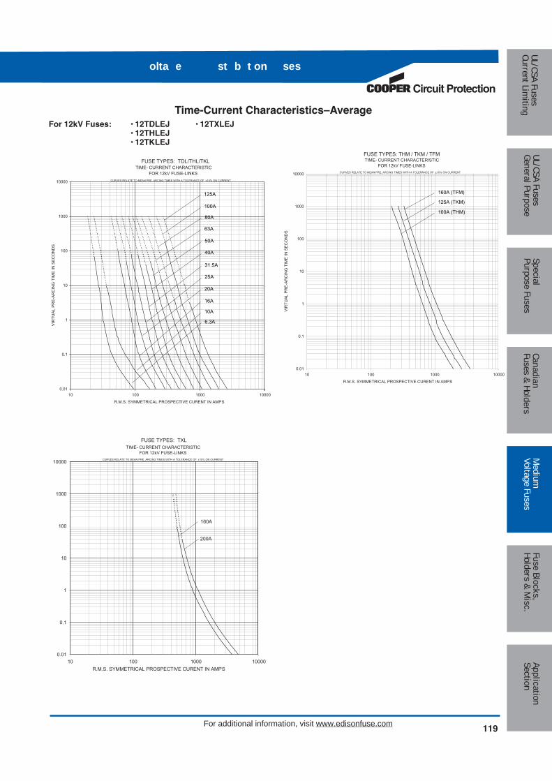
Circuit Protection
119
Medium
Voltage FusesUL/CSA FusesCurrent Lim
itingUL/CSA FusesGeneral Purpose
SpecialPurpose Fuses
CanadianFuses & Holders
ApplicationSection
Fuse Blocks,Holders & M
isc.
For additional information, visit www.edisonfuse.com
olta e st b t on ses
0.01
0.1
1
10
100
1000
10000
10 100 1000 10000
R.M.S. SYMMETRICAL PROSPECTIVE CURENT IN AMPS
VIR
TUAL
PR
E-AR
CIN
G T
IME
IN S
ECO
ND
S
TIME- CURRENT CHARACTERISTICFOR 12kV FUSE-LINKS
FUSE TYPES: TDL/THL/TKL
CURVES RELATE TO MEAN PRE_ARCING TIMES WITH A TOLERANCE OF ±10% ON CURRENT
20A
16A
10A
6.3A
25A
31.5A
40A
50A
63A
80A
100A
125A
0.01
0.1
1
10
100
1000
10000
10 100 1000 10000
R.M.S. SYMMETRICAL PROSPECTIVE CURENT IN AMPS
VIR
TUA
L P
RE
-AR
CIN
G T
IME
IN S
EC
ON
DS
TIME- CURRENT CHARACTERISTICFOR 12kV FUSE-LINKS
FUSE TYPES: THM / TKM / TFM
CURVES RELATE TO MEAN PRE_ARCING TIMES WITH A TOLERANCE OF ±10% ON CURRENT
100A (THM)
125A (TKM)
160A (TFM)
0.01
0.1
1
10
100
1000
10000
10 100 1000 10000R.M.S. SYMMETRICAL PROSPECTIVE CURENT IN AMPS
TIME- CURRENT CHARACTERISTICFOR 12kV FUSE-LINKS
FUSE TYPES: TXL
CURVES RELATE TO MEAN PRE_ARCING TIMES WITH A TOLERANCE OF ±10% ON CURRENT
160A
200A
Time-Current Characteristics–AverageFor 12kV Fuses: • 12TDLEJ • 12TXLEJ
• 12THLEJ• 12TKLEJ

120
Med
ium
Volta
ge F
uses
UL/C
SA F
uses
Curr
ent L
imiti
ngUL
/CSA
Fus
esGe
nera
l Pur
pose
Spec
ial
Purp
ose
Fuse
sCa
nadi
anFu
ses
& Ho
lder
sAp
plic
atio
nSe
ctio
nFu
se B
lock
s,Ho
lder
s &
Mis
c.
For additional information, visit www.edisonfuse.com
0.01
0.1
1
10
100
1000
10000
10 100 1000 10000R.M.S. SYMMETRICAL PROSPECTIVE CURENT IN AMPS
VIR
TUA
L P
RE
-AR
CIN
G T
IME
IN S
EC
ON
DS
TIME- CURRENT CHARACTERISTICFOR 17.5kV FUSE-LINKS
FUSE TYPES: TDL
CURVES RELATE TO MEAN PRE_ARCING TIMES WITH A TOLERANCE OF ±10% ON CURRENT
6.3A
10A
16A
40A
20A
25A
31.5A
0.01
0.1
1
10
100
1000
10000
00001000100101R.M.S. SYMMETRICAL PROSPECTIVE CURENT IN AMPS
VIR
TUA
L PR
E-A
RC
ING
TIM
E IN
SEC
ON
DS
TIME- CURRENT CHARACTERISTICFOR 17.5kV FUSE-LINKS
FUSE TYPES: TDM/THM/TKM
CURVES RELATE TO MEAN PRE_ARCING TIMES WITH A TOLERANCE OF ±10% ON CURRENT
20A
16A
10A
6.3A
25A
31.5A
40A
50A
63A
80A
100A
125A
0.01
0.1
1
10
100
1000
10000
10 100 1000 10000R.M.S. SYMMETRICAL PROSPECTIVE CURENT IN AMPS
VIR
TUA
L P
RE
-AR
CIN
G T
IME
IN S
EC
ON
DS
TIME- CURRENT CHARACTERISTICFOR 17.5kV FUSE-LINKS
FUSE TYPES: TFL
CURVES RELATE TO MEAN PRE_ARCING TIMES WITH A TOLERANCE OF ±10% ON CURRENT
50A
Time-Current Characteristics–AverageFor 17.5kV Fuses: • 17.5TDLSJ • 17.5THMEJ
• 17.5TFLSJ • 17.5TKMEJ• 17.5TDMEJ
olta e st b t on ses

Circuit Protection
121
Medium
Voltage FusesUL/CSA FusesCurrent Lim
itingUL/CSA FusesGeneral Purpose
SpecialPurpose Fuses
CanadianFuses & Holders
ApplicationSection
Fuse Blocks,Holders & M
isc.
For additional information, visit www.edisonfuse.com
olta e st b t on ses
A
A0.43"
10.8mm
0.99"25.0mm
4.06"103mm
Average Time-Current CurvesFor 24-27.6kV Fuses: • 24TDMEJ • 24TXMEJ
• 24THMEJ• 24TFMEJ
0.01
0.1
1
10
100
1000
10000
10 100 1000 10000
R.M.S. SYMMETRICAL PROSPECTIVE CURENT IN AMPS
VIR
TUA
L P
RE
-AR
CIN
G T
IME
IN S
EC
ON
DS
TIME- CURRENT CHARACTERISTICFOR 24kV FUSE-LINKS
FUSE TYPES: TDM/THM/TFM
CURVES RELATE TO MEAN PRE_ARCING TIMES WITH A TOLERANCE OF ±10% ON CURRENT
20A
16A
10A
6.3A
25A
31.5A
40A
50A
63A
80A
0.01
0.1
1
10
100
1000
10000
10 100 1000 10000R.M.S. SYMMETRICAL PROSPECTIVE CURENT IN AMPS
VIR
TUA
L P
RE
-AR
CIN
G T
IME
IN S
EC
ON
DS
TIME- CURRENT CHARACTERISTICFOR 24kV FUSE-LINKS
FUSE TYPES: TFM / TXM
CURVES RELATE TO MEAN PRE_ARCING TIMES WITH A TOLERANCE OF ±10% ON CURRENT
100A
125A
160A
Part No. 270303For Standard Duty (up to 200A)
1.77"45.0mm
3.50"88.9mm
1.19"30.2mm
2.5"63.5mm
0.38"9.5mm
4.50"114.3mm
1.5"38.1mm
Part No. A3354745Heavy Duty
DIN FuseclipsSuitable for use with all DIN HV fuses having 45mm end fittings.
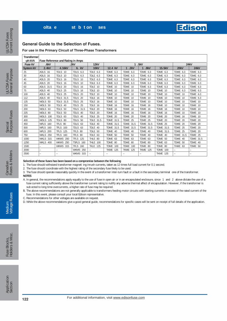
122
Med
ium
Volta
ge F
uses
UL/C
SA F
uses
Curr
ent L
imiti
ngUL
/CSA
Fus
esGe
nera
l Pur
pose
Spec
ial
Purp
ose
Fuse
sCa
nadi
anFu
ses
& Ho
lder
sAp
plic
atio
nSe
ctio
nFu
se B
lock
s,Ho
lder
s &
Mis
c.
For additional information, visit www.edisonfuse.com
Transformer-ph kVA Fuse Reference and Rating in AmpsFuse kV .6kV .2kV 12kV 1 .5kV 24kV
System kV 2.4kV 4.16kV 6. kV 10kV 12.4 kV 1 .2kV 1 .8kV 15.5kV 20kV 24kV25 ADLS 16 TDLS 10 TDLS 6.3 TDLE 6.3 TDME 6.3 TDME 6.3 TDME 6.3 TDME 6.3 TDME 6.3 TDME 6.330 ADLS 16 TDLS 10 TDLS 6.3 TDLE 6.3 TDME 6.3 TDME 6.3 TDME 6.3 TDME 6.3 TDME 6.3 TDME 6.340 ADLS 20 TDLS 16 TDLS 10 TDLE 6.3 TDME 6.3 TDME 6.3 TDME 6.3 TDME 6.3 TDME 6.3 TDME 6.345 ADLS 20 TDLS 16 TDLS 10 TDLE 6.3 TDME 6.3 TDME 6.3 TDME 6.3 TDME 6.3 TDME 6.3 TDME 6.363 ADLS 31.5 TDLS 20 TDLS 16 TDLE 10 TDME 10 TDME 10 TDME 6.3 TDME 6.3 TDME 6.3 TDME 6.375 ADLS 40 TDLS 25 TDLS 16 TDLE 10 TDME 10 TDME 10 TDME 10 TDME 10 TDME 6.3 TDME 6.3100 ADLS 40 TDLS 25 TDLS 20 TDLE 10 TDME 10 TDME 10 TDME 10 TDME 10 TDME 10 TDME 6.3112 ADLS 40 TDLS 31.5 TDLS 20 TDLE 16 TDME 10 TDME 10 TDME 10 TDME 10 TDME 10 TDME 6.3125 WDLS 50 TDLS 31.5 TDLS 25 TDLE 16 TDME 10 TDME 10 TDME 10 TDME 10 TDME 10 TDME 10150 WDLS 50 TDLS 40 TDLS 25 TDLE 16 TDME 16 TDME 16 TDME 16 TDME 10 TDME 10 TDME 10200 WDLS 63 TDLS 50 TDLS 31.5 TDLE 20 TDME 16 TDME 16 TDME 16 TDME 16 TDME 10 TDME 10225 WDLS 80 TDLS 50 TDLS 40 TDLE 20 TDME 16 TDME 16 TDME 16 TDME 16 TDME 10 TDME 10300 WDLS 100 TDLS 63 TDLS 40 TDLE 25 TDME 20 TDME 20 TDME 20 TDME 20 TDME 16 TDME 10400 WDLS 125 TDLS 80 TDLS 50 TDLE 31.5 TDME 31.5 TDME 25 TDME 25 TDME 20 TDME 20 TDME 20450 WFLS 160 TFLS 80 TDLS 63 TDLE 40 TDME 31.5 TDME 31.5 TDME 31.5 TDME 25 TDME 20 TDME 20500 WFLS 160 TFLS 100 TDLS 63 TDLE 40 TDME 31.5 TDME 31.5 TDME 31.5 TDME 31.5 TDME 25 TDME 20600 WFLS 200 TFLS 125 TFLS 80 TDLE 50 TDME 40 TDME 40 TDME 40 TDME 31.5 TDME 25 TDME 20750 WKLS 250 TFLS 160 TFLS 80 TDLE 63 TDME 50 TDME 50 TDME 40 TDME 40 TDME 31.5 TDME 251000 WKLS 315 WKMS 200 TFLS 125 THLE 80 TDME 63 TDME 63 TDME 63 TDME 50 TDME 40 TDME 31.51250 WKLS 400 WKMS 250 TSFLS 160 THLE 100 TDME 80 TDME 80 TDME 80 TDME 63 TDME 50 TDME 401500 – WKMS 315 TFLS 160 TKLE 125 TDME 100 TDME 100 TDME 80 TDME 80 THME 63 TDME 502000 – – WKMS 250 – TKME 125 TKME 125 TKME 125 TDME 100 – –2500 – – WKMS 315 – – – – TKME 125 – –
General Guide to the Selection of Fuses.
For use in the Primary Circuit of Three-Phase Transformers
Selection of these fuses has been based on a compromise between the following1. The fuse should withstand transformer magneti ing inrush currents, taken as 12 times full load current for 0.1 second.2. The fuse should coordinate with the highest rating of the secondary fuse likely to be used.3. The fuse should operate reasonably quickly in the event of a transformer inter-turn fault or a fault in the secondary terminal one of the transformer.NOTESA. In general, the recommendations apply equally to the use of fuse in open air or in an encapsulated enclosure, since 1 and 2 above dictate the use of a
fuse current rating sufficiently above the transformer current rating to nullify any adverse thermal affect of encapsulation. However, if the transformer issub ected to long time overcurrents, a higher rate of fuse may be required.
B. The above recommendations are not generally applicable to transformers feeding motor circuits with starting currents in excess of the rated current of thefuse. In this event, please consult your local Edison representative.
C. Recommendations for other voltages are available on request.D. While the above recommendations give a good general guide, recommendations for specific cases will be sent on receipt of full details of the application.
olta e st b t on ses
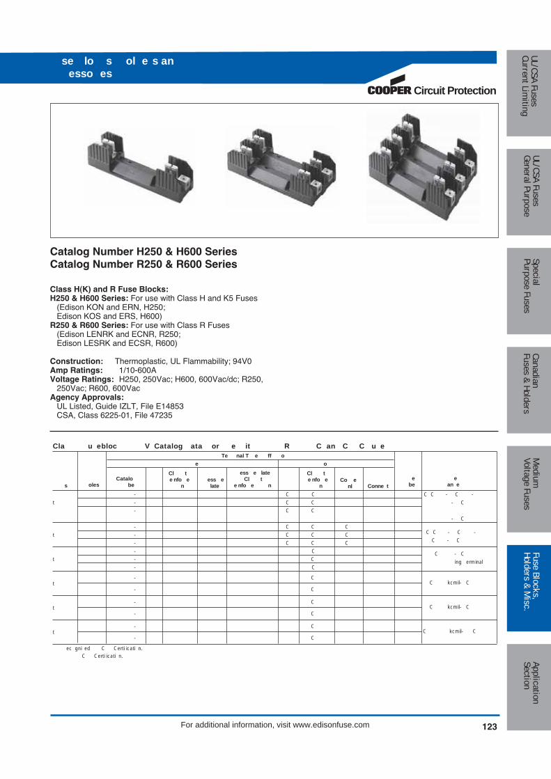
123
Medium
Voltage FusesUL/CSA FusesCurrent Lim
itingUL/CSA FusesGeneral Purpose
SpecialPurpose Fuses
CanadianFuses & Holders
ApplicationSection
Fuse Blocks,Holders & M
isc.
For additional information, visit www.edisonfuse.com
Circuit Protection
se lo s ol e s anesso es
Catalog Number H250 & H600 SeriesCatalog Number R250 & R600 Series
Class H(K) and R Fuse Blocks:H250 & H600 Series: For use with Class H and K5 Fuses
(Edison KON and ERN, H250;Edison KOS and ERS, H600)
R250 & R600 Series: For use with Class R Fuses(Edison LENRK and ECNR, R250;Edison LESRK and ECSR, R600)
Construction: Thermoplastic, UL Flammability; 94V0Amp Ratings: 1/10-600AVoltage Ratings: H250, 250Vac; H600, 600Vac/dc; R250,
250Vac; R600, 600VacAgency Approvals:
UL Listed, Guide IZLT, File E14853CSA, Class 6225-01, File 47235
Cla u ebloc V Catalog ata or e it R C an C C u eTe nal T e ff o
e o
- C C C C - C -
t - C C - C
- C C
- C
- C C CC C - C - t - C C C
C - C - C C C
- C
t - CC - C
- C ing erminal
- CC kcmil- Ct
- C
- CC kcmil- Ct
- C
- CC kcmil- Ct
- C
ec gni ed C Certi icati n. C Certi icati n.
sCatalo
beess elate
ess e late Cl t
e nfo e nCo e
nle
an e
Conne t
Cl t e nfo e
n
Cl t e nfo e
ne
beoles
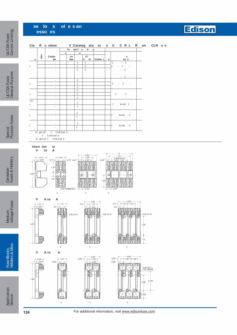
Cla R u ebloc V Catalog ata or e it C R L R an CLR u eTe nal T e ff o
e o Catalo es Cl e
be late C nl Conne t o an e- C C C - C
t - C C C - C -
- C C - C
- C
- C
t - C C - C -
- C
- C
t - C C - C
- C
101- C C kcmil- C t- C
- Ct C kcmil- C
- C
- Ct C kcmil- C
- C
ec gni ed C Certi icati n. C Certi icati n. ec gni ed C Certi icati n
oles
s
1.41"0.22"
1.09"
3.03"
0.5"
0.17" 0.75" 0.25"1.25"0.95"
0.22" DIAMETER
0.41"
2.05"
2 SPACES AT0.95" - 1.91"
2.5"3"
0.55"
1.27"
1.52"
0.55"
imen ion inV to A
G . G . G .
4.25
0.271.73 1.5
0.5
2.810.5 1.31
0.5
1.314.125
G
1.5
0.5
1.310.5
1.25
0.22 x 0.410.22 x 0.410.22 x 0.41
V A to A
G . G . G .
V A to A
G . G . G .
7.36"
0.25"2.06" 1.81"
0.62"
3.38"0.59"
0.62"
4.94"
2.38"
2.125"
0.62"
0.28" DIA. x0.5" C'BORE
0.59"1.56" 1.56"1.56"
3.125"
124 For additional information, visit www.edisonfuse.com
Appl
icat
ion
Sect
ion
Fuse
Blo
cks,
Hold
ers
& M
isc.
Med
ium
Volta
ge F
uses
Cana
dian
Fuse
s &
Hold
ers
Spec
ial
Purp
ose
Fuse
sUL
/CSA
Fus
esGe
nera
l Pur
pose
UL/C
SA F
uses
Curr
ent L
imiti
ng
se lo s ol e s anesso es

se lo s ol e s anesso es
Circuit Protection
125
Medium
Voltage FusesUL/CSA FusesCurrent Lim
itingUL/CSA FusesGeneral Purpose
SpecialPurpose Fuses
CanadianFuses & Holders
ApplicationSection
Fuse Blocks,Holders & M
isc.
For additional information, visit www.edisonfuse.com
se lo s ol e s anesso es
V A to A V A to A
3.150.750.31 0.5 2.0
0.75"C'BORE
0.34DIAMETER
3.0
3.0
2.06
7.125
V A to A
4.01.00.31 0.63 1.75
0.75"C'BORE
0.34DIAMETER
3.0
3.0
3.02
9.06
V A to A
4.971.00.31 1.125 1.75
0.75"C'BORE
0.34DIAMETER
4.0
3.0
4.0
11.0
G . G .
3.4"
4.5"
1" 0.5"
EYELETS TO ACCEPT0.25" DIA. SCREW
0.34" DIA. HOLE THROUGH
8"6"
5"3"
2"
3"
2.06"
7.13"
9"
G .
G .
V A to A
G .
4.00.34" DIA. HOLE THROUGH
9.06
4.01.0
10.889.250.82
2.5
V A to A
G .
5.00.34" DIA. HOLE THROUGH
11.0
4.971.0
14.7411.01.87
3.0

Cla u ebloc V Catalog ata or e it S RS an C SC u eTe nal T e ff o
e o
- C CC C - C - t - C C - C
- C C
- C C
t - C C C C - C -
- C C
- C
t - C C - C
- C
- CC kcmil- Ct
- C
- CC kcmil- Ct
- C
- CC kcmil- Ct
- C
C Certi icati n. ec gni ed C Certi icati n
ess elate
ess e late Cl t
e nfo e ne
an e
Cl t e nfo e
ne
besCatalo
be
Cl t e nfo e
noles
Cla R u ebloc V Catalog ata or e it L SR CSR an SCLR u eTe nal T e ff o
e o Catalo es Cl e
be late C nl o an e- C C - C
t - C C C - C -
- C C - C
- C
t - C C - C -
- C
- C
t - C C - C
- C
- C Ct- C kcmil- C
- Ct C kcmil- C
- C
- C C kcmil- Ct- C
C Certi icati n. ec gni ed C Certi icati n
oles
s
126 For additional information, visit www.edisonfuse.com
Appl
icat
ion
Sect
ion
Fuse
Blo
cks,
Hold
ers
& M
isc.
Med
ium
Volta
ge F
uses
Cana
dian
Fuse
s &
Hold
ers
Spec
ial
Purp
ose
Fuse
sUL
/CSA
Fus
esGe
nera
l Pur
pose
UL/C
SA F
uses
Curr
ent L
imiti
ng
se lo s ol e s anesso es

Circuit Protection
127
Medium
Voltage FusesUL/CSA FusesCurrent Lim
itingUL/CSA FusesGeneral Purpose
SpecialPurpose Fuses
CanadianFuses & Holders
ApplicationSection
Fuse Blocks,Holders & M
isc.
For additional information, visit www.edisonfuse.com
se lo s ol e s anesso es
6.25
0.261.73 1.54
0.62
2.900.25 1.56
0.62
1.564.25
3.13
1.56
0.62
1.560.25
0.28 x 0.50.28 x 0.5 0.28 x 0.5
7.36"
0.25"2.06" 1.81"
0.62"
3.38"0.59"
0.62"
4.94"
2.38"
2.125"
0.62"
0.28" DIA. x0.5" C'BORE
0.59"1.56" 1.56"1.56"
3.125"
ens ons nto
to
0.880.88
0.67 1.814.03
2.22
0.28 x 0.50.28 x 0.5
0.880.67 1.81 1.81
0.28 x 0.5
5.84
9.5
0.342.38
4.25
2.63
to

3.150.750.31 0.5 2.0
0.75"C'BORE
0.34DIAMETER
3.0
3.0
3.31
9.63
to
6.5"8.0"
0.75" DIA.C'BORE0.50" Deep
0.34DIAMETER
9.0"
5.5"
9.58"
3.0"
2.04"
3.15"
0.75"
11.0"
0.34DIAMETER0.75" DIA.C'BORE0.67" Deep 14.00"
3.00"
4.987"
1.00"2.13"
15.26"
8.00"
9.25"
0.75" DIA.C'BORE0.67" Deep
0.34DIAMETER
11.63"
7.00"
12.00"
2.5"
4.02"
1.00"1.19"
to
to
1.00.56 0.63 1.75
0.75"C'BORE
0.34DIAMETER
3.0
4.5
12.0
4.02
3.0
1.00.56 1.125 1.75
0.75"C'BORE
0.34DIAMETER
4.0
5.5
14.0
4.987
3.0
128
se lo s ol e s anesso es
For additional information, visit www.edisonfuse.com
Appl
icat
ion
Sect
ion
Fuse
Blo
cks,
Hold
ers
& M
isc.
Med
ium
Volta
ge F
uses
Cana
dian
Fuse
s &
Hold
ers
Spec
ial
Purp
ose
Fuse
sUL
/CSA
Fus
esGe
nera
l Pur
pose
UL/C
SA F
uses
Curr
ent L
imiti
ng

Circuit Protection
129
Medium
Voltage FusesUL/CSA FusesCurrent Lim
itingUL/CSA FusesGeneral Purpose
SpecialPurpose Fuses
CanadianFuses & Holders
ApplicationSection
Fuse Blocks,Holders & M
isc.
For additional information, visit www.edisonfuse.com
se lo s ol e s anesso es
Catalog Number J600 Series
Class J Fuse Blocks:J600 Series: For use with Class J Fuses
(Edison JDL, JFL and CJ)Construction: Thermoplastic, UL Flammability; 94V0Amp Ratings: 1/2-600AVoltage Ratings: 600Vac/dcAgency Approvals:
UL Listed, Guide IZLT, File E14853CSA, Class 6225-01, File 47235
0.56"
8.875"
3.25"
1.75"
0.75"c'bore0.34" dia.
4"
2.375"
1.125"
1"
4.99"
3.5"
1.75"3"
0.625"
0.75"c'bore0.34"dia.
0.5"
7.5"
1"4"
0.56"
0.75"
3.1"
0.31"
6.125"
3.06"
2"3"
0.5"
0.75"c'bore
0.34"dia.
e 5. e 6. e 7.
1/2 to 60A 61 to 100A
101- 200A 201- 400A 401-600A
Dimensions - inches
Standard J Fuse Blocks (600V) Catalog DataCatalog Numbers
Pressure Box Box Lug w Fig. Max. WireAmps Screw Plate Lug Retaining Clip No. Size
1 60030-1S 60030-1P 60030-1C 60030-1CR 1C, CR 2-14 CU,
2-8 AL1/2–30 2 60030-2S 60030-2P 60030-2C 60030-2CR 2 COR 2-14 CU only
3 60030-3S 60030-3P 60030-3C 60030-3CR 3P, PR, S, SR
10-14 CU Only
1 — — 60060-1C 60060-1CR 1C, CR, 2-14CU/AL
31–60 2 — — 60060-2C 60060-2CR 2 COR 4-143 — — 60060-3C 60060-3CR 3 CU only
COR 1/0-8
61–100 3 — — — 60100-3CR 4 CU OnlyCR, CRQ 1/0-8CU/AL
to 200 1 — — —60200-1CR
5CR 250kcmil-6
60200-3CR CU/AL
to 400 1 — — —60400-1CR
7CR 500kcmil -4
60400-3CR CU/AL
to 600 1 — — — 60600-1CR 9 CR (2) 500kcmil-60600-3CR 4/0 CU/AL
† Clip reinforcing springs are standard on fuse blocks rated 100A and above. Available on 30A and 60A blocks by adding the letter “R” to the end of thepart number.
††Copper only connections available by changing “CR” suffix to “COR”.
Pole
s
0.30"2.28"
6.28"
0.94"
0.22"Dia.
0.5"C'Bore
1.583"5"
3.14"
1.75" 1.5"
2.250"
3.202"
0.750"
4.702"
2.250"
CLL
1.500"
4.005"
C
2.415"1.702"
0.750"
e e e ee
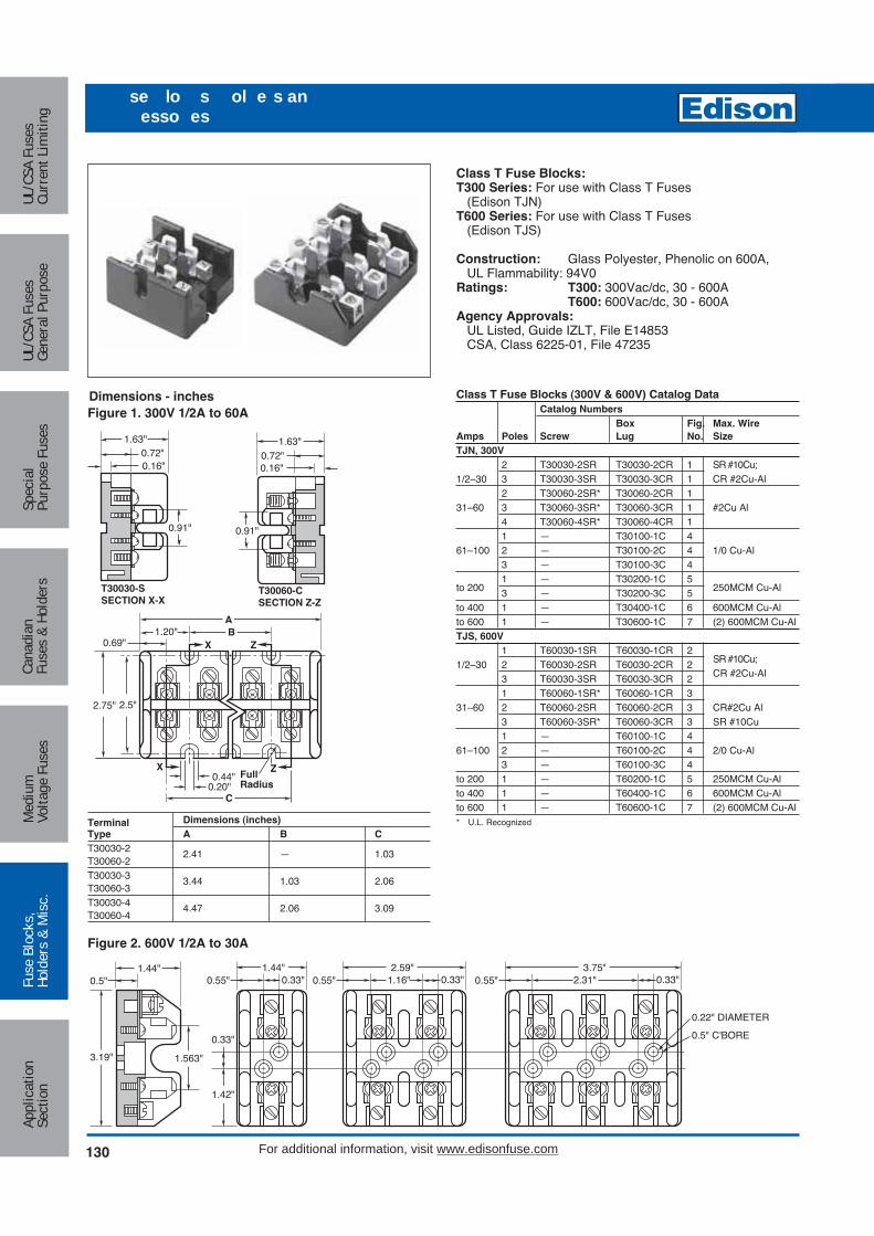
Terminal Dimensions (inches)Type A B CT30030-2 2.41 — 1.03T30060-2T30030-3 3.44 1.03 2.06T30060-3T30030-4 4.47 2.06 3.09T30060-4
Class T Fuse Blocks:T300 Series: For use with Class T Fuses
(Edison TJN)T600 Series: For use with Class T Fuses
(Edison TJS)
Construction: Glass Polyester, Phenolic on 600A,UL Flammability: 94V0
Ratings: T300: 300Vac/dc, 30 - 600AT600: 600Vac/dc, 30 - 600A
Agency Approvals:UL Listed, Guide IZLT, File E14853CSA, Class 6225-01, File 47235
Figure 2. 600V 1/2A to 30A
3.19"
1.44"
1.563"
0.33"
1.42"
0.5"1.44"
0.55" 0.33" 0.55"2.59"
1.16" 0.33" 0.55"3.75"
2.31" 0.33"
0.22" DIAMETER
0.5" C'BORE
Dimensions - inches Class T Fuse Blocks (300V & 600V) Catalog DataCatalog Numbers
Box Fig. Max. WireAmps Poles Screw Lug No. SizeTJN, 300V
2 T30030-2SR T30030-2CR 1 SR #10Cu;1/2–30 3 T30030-3SR T30030-3CR 1 CR #2Cu-Al
2 T30060-2SR* T30060-2CR 131–60 3 T30060-3SR* T30060-3CR 1 #2Cu Al
4 T30060-4SR* T30060-4CR 11 — T30100-1C 4
61–100 2 — T30100-2C 4 1/0 Cu-Al3 — T30100-3C 41 — T30200-1C 5
to 200 3 — T30200-3C 5 250MCM Cu-Al
to 400 1 — T30400-1C 6 600MCM Cu-Alto 600 1 — T30600-1C 7 (2) 600MCM Cu-AlTJS, 600V
1 T60030-1SR T60030-1CR 21/2–30 2 T60030-2SR T60030-2CR 2 SR #10Cu;
3 T60030-3SR T60030-3CR 2 CR #2Cu-Al
1 T60060-1SR* T60060-1CR 331–60 2 T60060-2SR T60060-2CR 3 CR#2Cu Al
3 T60060-3SR* T60060-3CR 3 SR #10Cu1 — T60100-1C 4
61–100 2 — T60100-2C 4 2/0 Cu-Al3 — T60100-3C 4
to 200 1 — T60200-1C 5 250MCM Cu-Alto 400 1 — T60400-1C 6 600MCM Cu-Alto 600 1 — T60600-1C 7 (2) 600MCM Cu-Al* U.L. Recognized
T30030-SSECTION X-X
0.91"
1.63"0.72"0.16"
T30060-CSECTION Z-Z
0.91"
1.63"0.72"0.16"
ZXFullRadius
ZX
0.44"0.20"
C
B1.20"A
0.69"
2.5"2.75"
Figure 1. 300V 1/2A to 60A
130 For additional information, visit www.edisonfuse.com
Appl
icat
ion
Sect
ion
Fuse
Blo
cks,
Hold
ers
& M
isc.
Med
ium
Volta
ge F
uses
Cana
dian
Fuse
s &
Hold
ers
Spec
ial
Purp
ose
Fuse
sUL
/CSA
Fus
esGe
nera
l Pur
pose
UL/C
SA F
uses
Curr
ent L
imiti
ng
se lo s ol e s anesso es
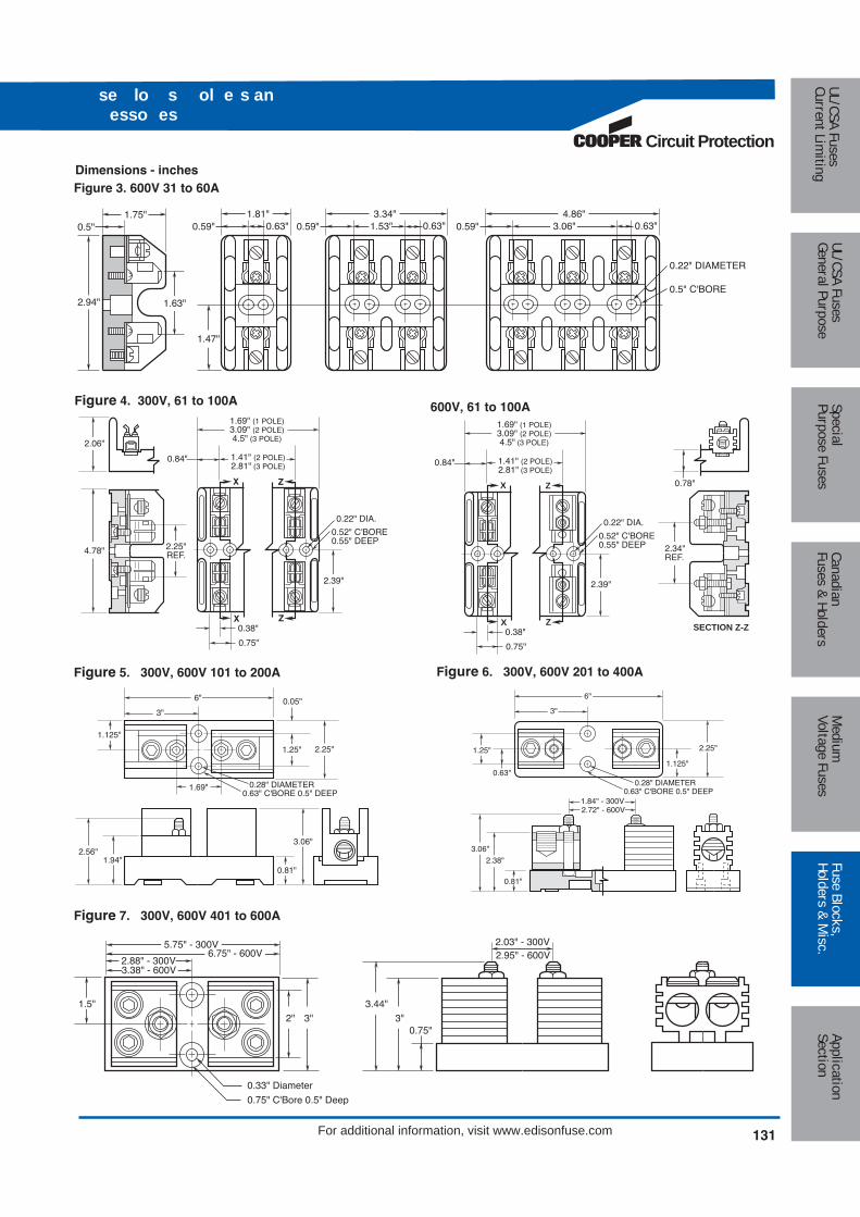
Circuit Protection
131
Medium
Voltage FusesUL/CSA FusesCurrent Lim
itingUL/CSA FusesGeneral Purpose
SpecialPurpose Fuses
CanadianFuses & Holders
ApplicationSection
Fuse Blocks,Holders & M
isc.
For additional information, visit www.edisonfuse.com
se lo s ol e s anesso es
Figure 4. 300V, 61 to 100A 600V, 61 to 100A
3"
6"
0.28" DIAMETER0.63" C'BORE 0.5" DEEP
1.125"
2.56"1.94"
0.81"
3.06"
1.69"
0.05"
1.25" 2.25"
Figure 5. 300V, 600V 101 to 200A
3.44"
0.75"3"
2.03" - 300V
3"2"
1.5"
5.75" - 300V
0.33" Diameter
0.75" C'Bore 0.5" Deep
2.88" - 300V3.38" - 600V
6.75" - 600V 2.95" - 600V
Figure 7. 300V, 600V 401 to 600A
6"
0.63" C'BORE 0.5" DEEP0.28" DIAMETER
1.125"
2.25"
0.63"
3"
1.84" - 300V
1.25"
0.81"
2.38"
3.06"
2.72" - 600V
Figure 6. 300V, 600V 201 to 400A
Figure 3. 600V 31 to 60A
2.94"
1.75"
1.63"
1.47"
0.5"1.81"
0.59" 0.63" 0.59"3.34"
1.53" 0.63" 0.59"4.86"
3.06" 0.63"
0.22" DIAMETER
0.5" C'BORE
Dimensions - inches
Z
Z
0.52" C'BORE0.55" DEEP
0.22" DIA.
X
X
2.39"
2.25"REF.4.78"
2.06"
1.69" (1 POLE)3.09" (2 POLE)4.5" (3 POLE)
1.41" (2 POLE)2.81" (3 POLE)
0.84"
0.38"
0.75"
Z
Z
0.52" C'BORE0.55" DEEP
0.22" DIA.
X
X
2.39"
1.69" (1 POLE)3.09" (2 POLE)4.5" (3 POLE)
1.41" (2 POLE)2.81" (3 POLE)
0.84"
0.38" SECTION Z-Z
0.78"
2.34"REF.
0.75"
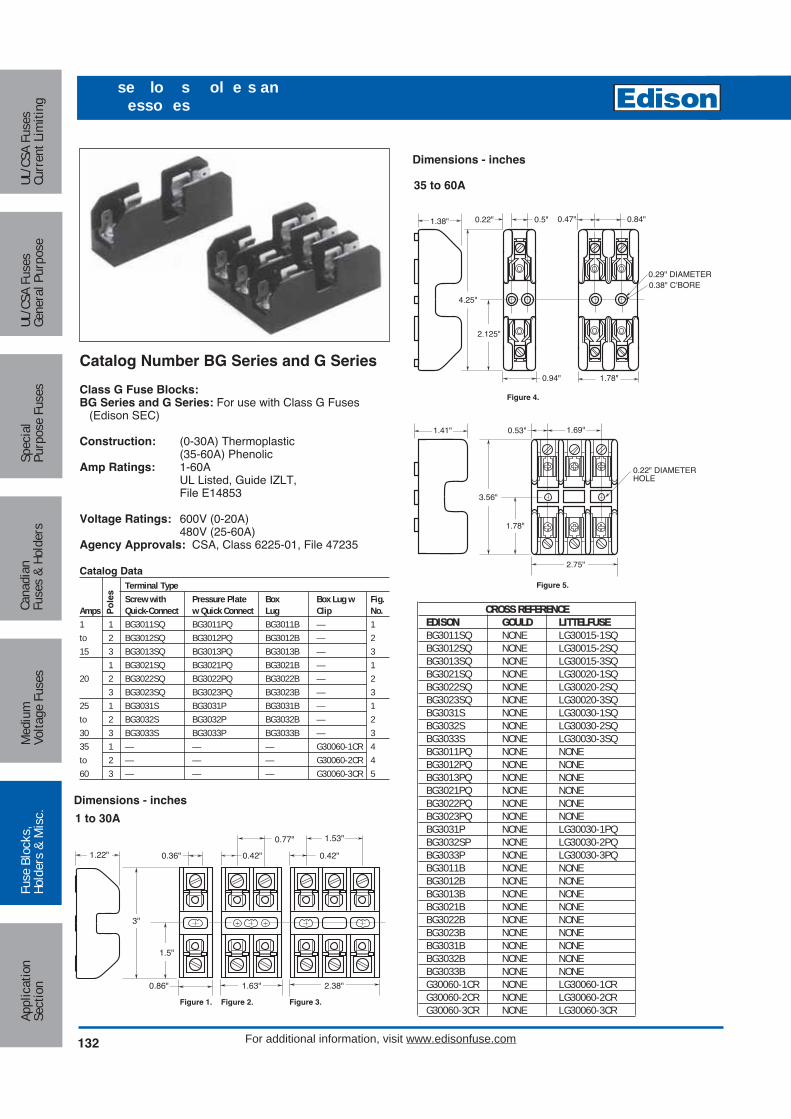
Catalog Number BG Series and G Series
Class G Fuse Blocks:BG Series and G Series: For use with Class G Fuses
(Edison SEC)
Construction: (0-30A) Thermoplastic(35-60A) Phenolic
Amp Ratings: 1-60AUL Listed, Guide IZLT,File E14853
Voltage Ratings: 600V (0-20A)480V (25-60A)
Agency Approvals: CSA, Class 6225-01, File 47235
Catalog DataTerminal TypeScrew with Pressure Plate Box Box Lug w Fig.
Amps Quick-Connect w Quick Connect Lug Clip No.1 1 BG3011SQ BG3011PQ BG3011B — 1to 2 BG3012SQ BG3012PQ BG3012B — 215 3 BG3013SQ BG3013PQ BG3013B — 3
1 BG3021SQ BG3021PQ BG3021B — 120 2 BG3022SQ BG3022PQ BG3022B — 2
3 BG3023SQ BG3023PQ BG3023B — 325 1 BG3031S BG3031P BG3031B — 1to 2 BG3032S BG3032P BG3032B — 230 3 BG3033S BG3033P BG3033B — 335 1 — — — G30060-1CR 4to 2 — — — G30060-2CR 460 3 — — — G30060-3CR 5
Po
les
0.42"
1.53"
0.42"
0.77"
3"
1.22"
1.5"
0.36"
0.86" 1.63" 2.38"
1 to 30A
35 to 60A
Figure 1. Figure 2. Figure 3.
Figure 4.
Figure 5.
1.38" 0.5"0.22" 0.47"
0.29" DIAMETER0.38" C'BORE
0.84"
1.78"0.94"
4.25"
1.41" 1.69"0.53"
2.125"
1.78"
3.56"
2.75"
0.22" DIAMETERHOLE
Dimensions - inches
132 For additional information, visit www.edisonfuse.com
Appl
icat
ion
Sect
ion
Fuse
Blo
cks,
Hold
ers
& M
isc.
Med
ium
Volta
ge F
uses
Cana
dian
Fuse
s &
Hold
ers
Spec
ial
Purp
ose
Fuse
sUL
/CSA
Fus
esGe
nera
l Pur
pose
UL/C
SA F
uses
Curr
ent L
imiti
ng
se lo s ol e s anesso es
Dimensions - inches
CROSS REFERENCEEDISON GOULD LITTELFUSEBG3011SQ NONE LG30015-1SQBG3012SQ NONE LG30015-2SQBG3013SQ NONE LG30015-3SQBG3021SQ NONE LG30020-1SQBG3022SQ NONE LG30020-2SQBG3023SQ NONE LG30020-3SQBG3031S NONE LG30030-1SQBG3032S NONE LG30030-2SQBG3033S NONE LG30030-3SQBG3011PQ NONE NONEBG3012PQ NONE NONEBG3013PQ NONE NONEBG3021PQ NONE NONEBG3022PQ NONE NONEBG3023PQ NONE NONEBG3031P NONE LG30030-1PQBG3032SP NONE LG30030-2PQBG3033P NONE LG30030-3PQBG3011B NONE NONEBG3012B NONE NONEBG3013B NONE NONEBG3021B NONE NONEBG3022B NONE NONEBG3023B NONE NONEBG3031B NONE NONEBG3032B NONE NONEBG3033B NONE NONEG30060-1CR NONE LG30060-1CRG30060-2CR NONE LG30060-2CRG30060-3CR NONE LG30060-3CR

Circuit Protection
133
Medium
Voltage FusesUL/CSA FusesCurrent Lim
itingUL/CSA FusesGeneral Purpose
SpecialPurpose Fuses
CanadianFuses & Holders
ApplicationSection
Fuse Blocks,Holders & M
isc.
For additional information, visit www.edisonfuse.com
se lo s ol e s anesso es
Catalog Number BC Series
Class CC Fuse Blocks:BC Series: For use with Class CC Fuses
(Edison EDCC, HCTR, and HCLR)
Construction: Base - ThermoplasticClips - Bright Tin-plated BronzeUL Flammability; 94V0
Ratings: 600Vac/dc, 30AAgency Approvals:
UL listed Guide IZLT, File 14853CSA, Class 6225-01, File 47235
1.625" + 0.015"(41.28mm + 0.38mm)
1.625" + 0.015"(41.28mm + 0.38mm)
3.000" + 0.015"(76.20mm + 0.38mm)
0.360"(9.14mm)
1 POLE
0.828" + 0.015"(21.03mm + 0.38mm)
0.200" + 0.003"(5.08mm + 0.08mm)
0.200" + 0.003"(5.08mm + 0.08mm)
0.425"(10.80mm)
1.530"(38.86mm)
0.200" + 0.003"(5.08mm + 0.08mm)
2 POLE 0.425"(10.80mm)
0.765"(19.43mm)
3 POLE
Catalog DataTerminal Type
Pressure Screw with Plate w/Quick Quick Box
Poles Connect Connect Lug
1/10 1 BC6031SQ BC6031P BC6031B
to 2 BC6032SQ BC6032P BC6032B
30 3 BC6033SQ BC6033P BC6033B
Dimensions - inches (mm)
Fuse Block
1.210" + 0.015"(30.73mm + 0.38mm)
CROSS REFERENCENEW OLDEDISON EDISON GOULD LITTELFUSEBC6031SQ EMR631-66 30311R L60030C-1SQBC6032SQ EMR632-66 30312R L60030C-2SQBC6033SQ EMR633-66 30313R L60030C-3SQBC6031PQ EMR631-77 30321R L60030C-1PQBC6032PQ EMR632-77 30322R L60030C-2PQBC6033PQ EMR633-77 30323R L60030C-3PQBC6031B EMR631-11 30351R L60030C-1BBC6032B EMR632-11 30352R L60030C-2BBC6033B EMR633-11 30353R L60030C-3B

Catalog Number BM Series Adapter for DIN and American Rails
Class M Supplementary Fuse Blocks:BM Series: For use with any 13⁄32˝ x 1 1⁄2˝ fuses
(Edison MCL, MEQ, MEN, and MOL)
Construction: Thermoplastic, UL Flammability; 94V0Ratings: 600Vac/dc, 30AAgency Approvals:
UL Recognized, Guide IZLT2, File E14853CSA, Class 6225-01, File 47235
Catalog Data (600Vac)Terminal Type
Screw withQuick Pressure Plate w/ Box Fig.
Amps Poles Connect Quick Connect Lug No.
1/10 1 BM6031SQ BM6031PQ BM6031B 1
to 2 BM6032SQ BM6032PQ BM6032B 2
30 3 BM6033SQ BM6033PQ BM6033B 3
Features:• Edison DIN rail adapters permit secure, positive snap-on
mounting of Edison 0 to 30 amp fuse blocks (one-, two-,or three-pole) on various size rails. (rail mountingeliminates costly and time consuming drilling, tapping,and screw mounting.)
• Molded from Lexan® 141.• Adapter mechanically locks into mounting hole of fuse
block in seconds to become an integral part of the block.• One adapter is required for Edison one- and two-pole
blocks. Two adapters are required for three-pole blocks.• With the exception of the 32mm DIN rail, all blocks with
adapters can be removed from a rail simply by pulling upits release tab.
• Use of rail end-stops on both sides of adapters is recommended.
Adapter Catalog Data (For 0-30A Fuse Blocks)
Fuse Block Rails Adapter
Class Type Size Color Cat. No.
CC 15mm (Symm.)G DIN 32mm (Asymm.) Black DRA-1*H (250V) 35mm (Symm.)
*R (250) 17/64” (Symm.)M Type American (also 35mm DIN) Gray DRA-2
Package Quantities: Standard - 10; Bulk - 100 (Cat. No. BK/DRA-1 or BK/DRA-1.)*Mounting on 15mm rails is not recommended.NOTE: New model Edison fuse blocks have elongated block-to-adapter mounting holes(old style fuse blocks will not accept the rail adapters).
Dimensions - inches (mm)
0.42"(10.7mm)
1.53"(38.9mm)
0.42"(10.7mm)
0.77"(19.4mm)
3"(76.2mm)
1.22"(31.0mm)
1.5"(38.1mm)
0.36"(9.1mm)
0.86"(21.8mm)
1.63"(41.3mm)
2.38"(60.3mm)
1/10 to 30A
Figure 1. Figure 2. Figure 3.
134 For additional information, visit www.edisonfuse.com
Appl
icat
ion
Sect
ion
Fuse
Blo
cks,
Hold
ers
& M
isc.
Med
ium
Volta
ge F
uses
Cana
dian
Fuse
s &
Hold
ers
Spec
ial
Purp
ose
Fuse
sUL
/CSA
Fus
esGe
nera
l Pur
pose
UL/C
SA F
uses
Curr
ent L
imiti
ng
se lo s ol e s anesso es
CROSS REFERENCENEW OLDEDISON EDISON GOULD LITTELFUSEBM6031SQ EM631-33 30311 L60030M-1SQBM6032SQ EM632-33 30312 L60030M-2SQBM6033SQ EM633-33 30313 L60030M-3SQBM6031PQ EM631-44 30321 L60030M-1PQBM6032PQ EM632-44 30322 L60030M-2PQBM6033PQ EM633-44 30323 L60030M-3PQBM6031B EM631-11 30351 L60030M-1BBM6032B EM632-11 30352 L60030M-2BBM6033B EM633-11 30353 L60030M-3B

Circuit Protection
135
Medium
Voltage FusesUL/CSA FusesCurrent Lim
itingUL/CSA FusesGeneral Purpose
SpecialPurpose Fuses
CanadianFuses & Holders
ApplicationSection
Fuse Blocks,Holders & M
isc.
For additional information, visit www.edisonfuse.com
se lo s ol e s anesso es
Catalog Number BH Series
Block Series:BH Series: For use with Edison high speed semiconductorand “bolt-in” fuses
Base: Light weight, high temperature thermoplasticMounting Studs: Plated steelNut: Plated steelWasher: Spring steelAgency Approvals:
UL Recognized, Guide IZLT2/IZLT8, File E14853 up to 700VCSA, Class 6225-01, File 47235 up to 700V
Contact Edison Customer Satisfaction for ordering informationand dimensional data.
Catalog Code DescriptionBlock Series
B -
NOTES 1. The 4 connector must be used with either the 7/16 - 14 or the 3/8 - 16 stud.2. The only compatible connector for the 7/16 - 14 stud is 4.3. Always check applicable end use standards for required spacing between blocks, fuses or other hardware.4. For applications above 700V, consult appropriate electrical standard for proper creepage distances, clearance distances and insulator voltage withstand ratings.
Agency Approval0 No agency approval1 UL Recognition and CSA Certification2 UL Recognition only3 cURus
Fuseblock Base0 Small base for 0-200 amp fuses, 0-700V1 Medium base, for 0-400 amp fuses, 0-2500V2 Medium base, for 0-600 amp fuses, 0-5000V3 Large base, for 0-700 amp, 0-1250V
Wire Connector0 No connector1 1 Hole for 14 - 2/0 copper wire
(for use with base 0)2 2 Hole for 14 - 1/0 copper wire
(for use with base 0)3 2 Hole for 6 - 250 MCM copper wire
(for use with base 1, 2, & 3)4 2 Hole for 14 - 500 MCM copper cable
(for use with base 3)See Note 1 below
Stud Size1 1⁄4 - 20 (for use with bases 0, 1, & 2) 2 5⁄16 - 18 (For use with bases 0, 1, & 2)3 3⁄8 - 16 (for use with bases 0, 1, 2 & 3)4 7⁄16 - 14 (for use with base 3)See Note 2 below.5 3⁄8 - 16 (for use with base 3)
Catalog Num ersBH-0001 BH-0122 BH-2001 BH-3004BH-0002 BH-1001 BH-2002 BH-3033BH-0003 BH-1002 BH-2003 BH-3144BH-0111 BH-1003 BH-2031 BH-3145BH-0112 BH-1131 BH-2032 —BH-0113 BH-1132 BH-2033 —BH-0121 BH-1133 BH-3003 —

Box Cover Units
For Plug Fuses
Plug fuse box cover units provide a simple, inexpensive wayto protect small motors with Edison-type “T”, “TL”, “TC”, “P”and “W” plug fuses. Box cover units are easily installed instandard electrical boxes. By using fuses sized at the amprating of a motor or slightly larger, optimum overload andshort-circuit protection is provided. Box cover units are ULListed.
Fuse Holder
On/Off Switch
Receptacle
Switch Light
SSY-RL
Selection Data — Plug Fuse Box Cover UnitsReceptacle Motor Agency
Box Cover Fuseholder Outlet to Load Switch Switch Size ListingCat. No. Type Box Single Double 125Vac 250Vac Control Light (Max.) General Data CertificationSOU X 3⁄4 Hp 125V, 15A UL, CSASRU 2 1⁄4 Handy X X 1⁄2 Hp 125V, 15A ULSSU X X 1⁄2 Hp 125Vac (do not use on DC), 15A UL, CSASOW X 3⁄4 Hp 125V, 15A UL, CSASRW 2 3⁄4 Switch X X 1⁄2 Hp 125V, 15A ULSSW X X 1⁄2 Hp 125Vac (do not use on DC), 15A UL, CSASO X 3⁄4 Hp 125V, 15A UL, CSASR 4 Octagon X X 1⁄2 Hp 125V, 15A ULSS X X 1⁄2 Hp 125Vac (do not use on DC), 15A UL, CSASO X 3⁄4 Hp 125V, 15A UL, CSASR X X 1⁄2 Hp 125V, 15A ULSS X X 1⁄2 Hp 125Vac (do not use on DC), 15A UL, CSASS -RL 4 Square X X X X 1⁄2 Hp 125Vac (do not use on DC), 15A —ST X X* 1⁄2 Hp* 125Vac (do not use on DC)*, 15A UL
SC X X(2)** 1⁄2 Hp(2)** 125Vac (do not use on DC) ULcan protect two motors**, 15ASO -B X 3⁄4 Hp 125V, protects two motors, 15A ULSKA 4 11⁄16 Square X X(15A) 2 Hp 250V, 15A single-phase ULSSN Single Gang X X 1⁄2 Hp 125V, 15A Weatherproof UL
Switch turns power to fused load OFF or ON.Switch light indicates power to load (dark when switch OFF or fuse open).
* Double-pole switch opens both sides of circuit. STY can be used for two separate 125V motors not larger than 1⁄2 Hp with the common switch, or a single motor notlarger than 2 Hp at 250V (Maximum of 150V to ground).
** The SCY unit can be used for protection of a single motor not larger than 2Hp at 250V (Maximum of 150V to ground).UL Guide AM , File E6491 CSA Class 6225-01, File 47235.
136 For additional information, visit www.edisonfuse.com
Appl
icat
ion
Sect
ion
Fuse
Blo
cks,
Hold
ers
& M
isc.
Med
ium
Volta
ge F
uses
Cana
dian
Fuse
s &
Hold
ers
Spec
ial
Purp
ose
Fuse
sUL
/CSA
Fus
esGe
nera
l Pur
pose
UL/C
SA F
uses
Curr
ent L
imiti
ng
o Co e n tsfo l ses
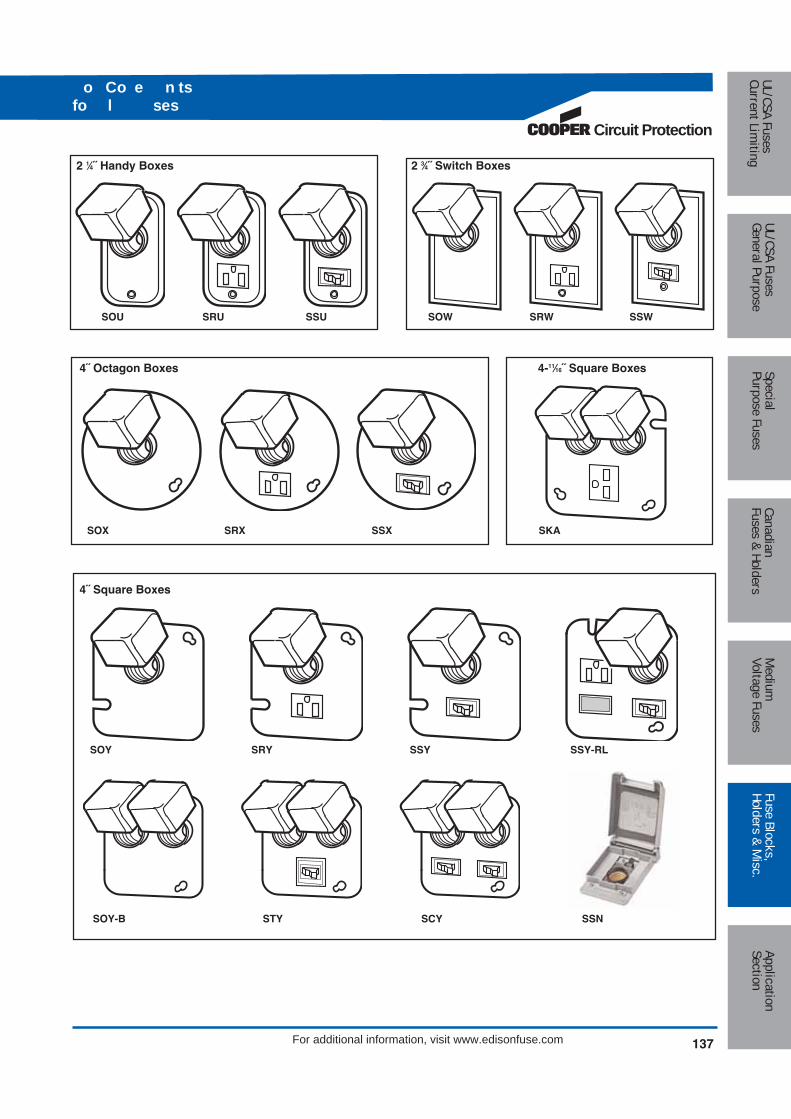
Circuit Protection
137
Medium
Voltage FusesUL/CSA FusesCurrent Lim
itingUL/CSA FusesGeneral Purpose
SpecialPurpose Fuses
CanadianFuses & Holders
ApplicationSection
Fuse Blocks,Holders & M
isc.
For additional information, visit www.edisonfuse.com
o Co e n tsfo l ses
2 1⁄4˝ Handy Boxes 2 3⁄4˝ Switch Boxes
4˝ Octagon Boxes 4-11⁄16˝ Square Boxes
SOU SRU SSU SOW SRW SSW
SOX SRX SSX SKA
4˝ Square Boxes
SOY SRY SSY SSY-RL
SOY-B STY SCY SSN

Features and Benefits• High Short-Circuit Current Ratings (SCCR) up to 200kA
• Suitable for installation in wireways and industrial controlpanel feeder and branch circuits
• Small footprint saves panel space
• Enclosed for enhanced safety
Agency and Standards• UL Listed 1953, Guide QPQS, File E256146
• CSA Certified, Class 6228-01, File 700490
• CE
• IEC 60947-7-1; IEC 60539
Electrical:• Short-Circuit Current Ratings up to 200kA, see table next
page
• Ampacities up to 760 amps
• 600Vac/dc (UL 1953), 690Vac/dc (IEC)
• 75°C Rated connectors
• Cu Wire range 14AWG to 500kcmil (2.5 to 240mm≈)
Mechanical:• DIN rail or panel mount (EPDB306 & EPDB702 panel
mount only)
• Sliding DIN rail latch for easy mounting
• Captive termination screws, so screws do not get misplaced
• Screws backed out at the factory to save conductorinstallation time
• Single-pole, gang mountable for multiple pole applications
• Flammability, UL 94V0
• Tin-plated Al connectors suitable for Cu conductors
• Elongated hole for panel mounting - easier mounting withgreater flexibility in matching up with drilled panel holes
• DIN rail end anchors required to prevent damage to blockwhen torquing, anchors available from third-party supplier
138 For additional information, visit www.edisonfuse.com
Appl
icat
ion
Sect
ion
Fuse
Blo
cks,
Hold
ers
& M
isc.
Med
ium
Volta
ge F
uses
Cana
dian
Fuse
s &
Hold
ers
Spec
ial
Purp
ose
Fuse
sUL
/CSA
Fus
esGe
nera
l Pur
pose
UL/C
SA F
uses
Curr
ent L
imiti
ng
n lose o e st b t on lo s e es

Circuit Protection
139
Medium
Voltage FusesUL/CSA FusesCurrent Lim
itingUL/CSA FusesGeneral Purpose
SpecialPurpose Fuses
CanadianFuses & Holders
ApplicationSection
Fuse Blocks,Holders & M
isc.
For additional information, visit www.edisonfuse.com
n lose o e st b t on lo s e es
C U W ire R angeT orque
Lb -In (N �m )T rim Length in (m m ) H ex K ey C U W ire R ange T orque
Lb -In (N �m )T rim Length in (m m ) H ex K ey L ineside
in (m m )Loadside in (m m )
M in . Enclosure S ize - inch
4 to 6 A W G
25 to 16m m2
35 (4 .0 )8 A W G
10m m2
25 (2 .8 )10 to 14 A W G
6 to 2 .5m m2
20 (2 .3 )
2 to 3 A W G
35m m2
50 (5 .7 )4 to 6 A W G
25 to 16m m2
45 (5 .1 )8 A W G
10m m2
40 (4 .5 )10 to 14 A W G
6 to 2 .5m m ² 35 (4 .0 )4 to 6 A W G
25 to 16m m2
35 (4 .0 )8 A W G
10m m2
25 (2 .8 )10 to 14 A W G
6 to 2 .5m m2
20 (2 .3 )
24 X 20 X 6 .75
36 X 30 X 12 .625
36 X 30 X 12 .625
16 X 16 X 6 .75
16 X 16 X 6 .75
36 X 30 X 12 .625
24 X 20 X 6 .750.314 (8 .0 )
0 .265 (6 .7 )
0 .718 (18 .2)
0 .875 (22 .2)
0 .87 (22 .1)
0 .687 (17 .5)
0 .718 (18 .2)
0 .875 (22 .2)
W ire C onnector H o le D iam eter
0.45 (11 .5)
0 .45 (11 .5)
0 .72 (18 .3)
0 .45 (11 .5)
0 .246 (6 .25)
0 .72 (18 .3)
500 K cm il to 6 A W G
240 to 16m m2
275 (31 .1)
275 (31 .1)
500 (56 .5)
350 K cm il to 6 A W G
150 to 16m m2
E P D B 512
E P D B 602
E P D B 702
E P D B 101
E P D B 104
E P D B 301
E P D B 306
1.25 (31 .8) 3 /8"
S eries E P D B
500 K cm il to 6 A W G
240 to 16m m2 500 (56 .5) 1 .25 (31 .8) 3 /8"
0 .55 (14) top row 1 (25 .4) m idd le row
1.22 (31) bo ttom row1/8"
350 K cm il to 4 A W G
185 to 25m m2 5/16"350 K cm il to 4 A W G
185 to 25m m2
300 K cm il to 4 A W G
150 to 25m m2 275 (31 .1)
1 .15 (29 .2) top row 1 .4 (35 .6) bo ttom row
1/4"
275 (31 .1) 1 .250 (31 .8) 5 /16" 1 .25 (31 .8)
0 .59 (15) top row 1.2 (30 .5) bo ttom row
1/8"
350 K cm il to 6 A W G
185 to 16m m2 275 (31 .1) 1 .35 (34 .3)
500 K cm il to 6 A W G
240 to 16m m2 500 (56 .5) 1 .25 (31 .8) 3 /8"
5 /16"
3 /16"
2 /0 to 8 A W G
70 to 10m m2 120 (13 .6) 0 .75 (19 .0) 3 /16"
0 .55 (14) top row 0.85 (21 .6) bo ttom row
1/8"
1 .25 (31 .8) 5 /16"
P art N um ber
L ineside Loadside
2/0 to 8 A W G
70 to 10m m2 110 (12 .4) 0 .85 (21 .6) 3 /16"
2 /0 to 8 A W G
70 to 10m m2 110 (12 .4) 0 .97 (24 .6)
L ineside LoadsideP art
N um ber Am ps W ire R ange W ire R angeL ine Load J T R K 1 R K 5
S C C R
L ine LoadA W G or
kcm ilA W G or
kcm il JD LTJS TJN
LE S R K LE N R K
E C S R E C N R
4 to 12 200 200 100 60 200 kA175 175 100 60 100 kA200 200 100 60 50 kA
2 to 6 400 400 200 100 200 kA200 200 100 30 50 kA175 175 100 30 100 kA
300 4 to 8 600 600 400 200 200 kA4 600 600 400 200 50 kA
6 to 14 200 200 100 30 50 kA350 350 600 600 400 200 200 kA
600 800* 600 400 200 kA600 800* 600 600 100 kA
400 to 6 400 to 6 600 600 400 200 100 kAA m pac ities 75°C per N E C
® Tab le 310 .16 and U L 508A Tab le 28 .1
*C lass L 800A (LC L 800) or less fuses su itab le fo r th is particu la r S C C R case.
S eries E P D B
E lectrica l
O pen ings per P o le
**C lass G 60A (S E C -60) o r less o r C lass C C 30A (E D C C 30, H C TR 30, H C LR 30) o r less a re su itab le fo r a ll the S C C R s in th is tab le .
E P D B 101
E P D B 104
E P D B 301
E P D B 306
E P D B 512
E P D B 602
E P D B 702 760A500kcm il to 6 A W G
240 to 16m m ²
600 200 100 kA600 800*
500kcm il to 6 A W G 240 to 16m m ²
500500
620A350kcm il to 4 A W G
185 to 25m m ²350kcm il to 4 A W G
185 to 12m m ² 300 to 4300 to 4
570A300kcm il to 4 A W G
150 to 25m m ²4 to 14 A W G 25 to 2 .5m m ²
100350kcm il to 6 A W G
185 to 16m m ²350kcm il to 6 A W G
185 to 16m m ²350 to 6
8 to 14
250 to 4
200 kA
380A500kcm il to 6 A W G
240 to 16m m ²2 to 14 A W G 35 to 2 .5m m ²
500 to 6
350 to 6 400 400 200310A
60 200 kA
175A2/0 to 8 A W G 70 to 10m m ²
4 to 14 A W G 25 to 2 .5m m ²
2/0 to 8 14
175A2/0 to 8 A W G 70 to 10m m ²
2/0 to 8 A W G 70 to 10m m ²
100
T erm inal C opper C onductor C apab ility S hort-C ircu it C urren t R ating D ataC onfiguration C onductors M ax Fuse C lass & Am p**
2/0 to 8 2 /0 to 8 200 200
Electrical Data
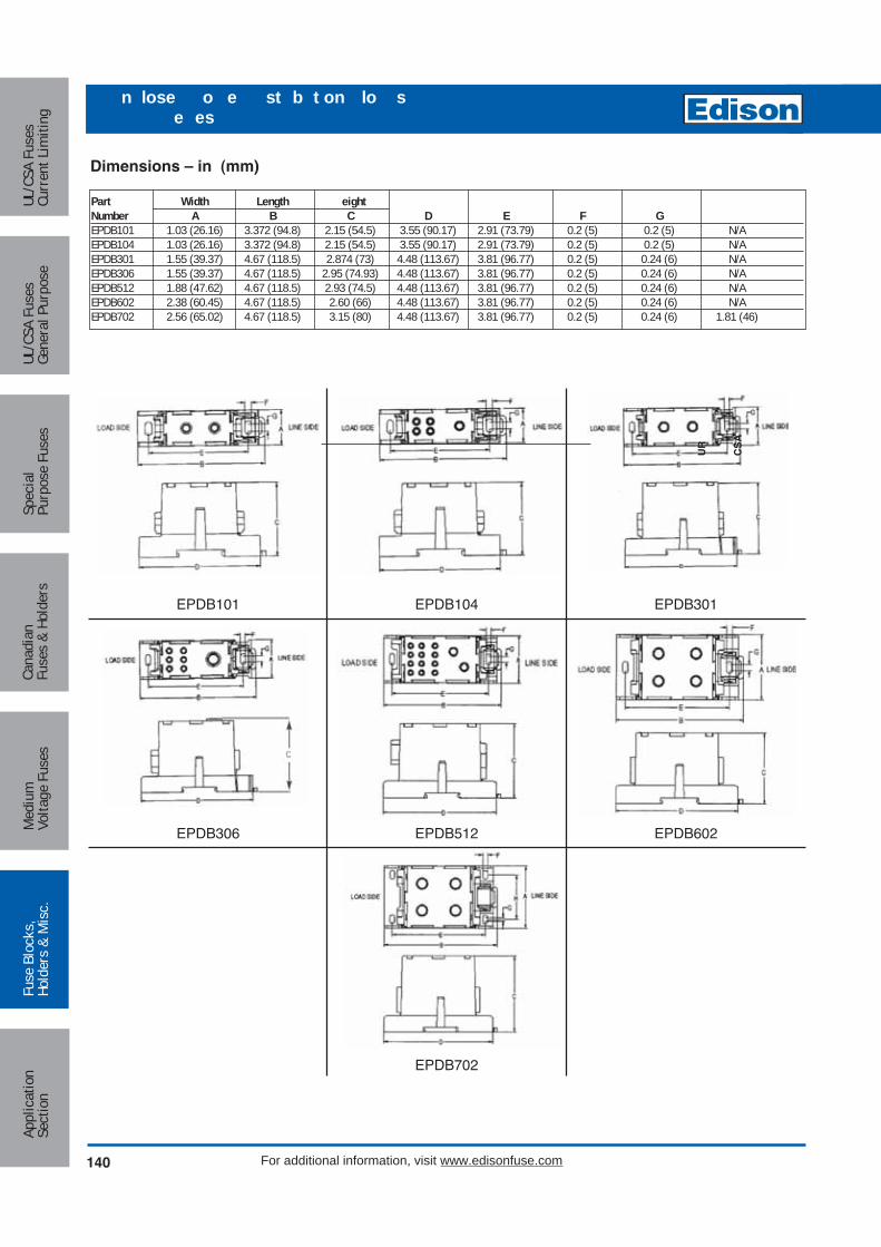
EPDB101 EPDB104 EPDB301
EPDB306 EPDB512 EPDB602
EPDB702
Part Width Length eightNumber A B C D E F GEPDB101 1.03 (26.16) 3.372 (94.8) 2.15 (54.5) 3.55 (90.17) 2.91 (73.79) 0.2 (5) 0.2 (5) N/AEPDB104 1.03 (26.16) 3.372 (94.8) 2.15 (54.5) 3.55 (90.17) 2.91 (73.79) 0.2 (5) 0.2 (5) N/AEPDB301 1.55 (39.37) 4.67 (118.5) 2.874 (73) 4.48 (113.67) 3.81 (96.77) 0.2 (5) 0.24 (6) N/AEPDB306 1.55 (39.37) 4.67 (118.5) 2.95 (74.93) 4.48 (113.67) 3.81 (96.77) 0.2 (5) 0.24 (6) N/AEPDB512 1.88 (47.62) 4.67 (118.5) 2.93 (74.5) 4.48 (113.67) 3.81 (96.77) 0.2 (5) 0.24 (6) N/AEPDB602 2.38 (60.45) 4.67 (118.5) 2.60 (66) 4.48 (113.67) 3.81 (96.77) 0.2 (5) 0.24 (6) N/AEPDB702 2.56 (65.02) 4.67 (118.5) 3.15 (80) 4.48 (113.67) 3.81 (96.77) 0.2 (5) 0.24 (6) 1.81 (46)
Dimensions – in (mm)
UR
CS
A
140 For additional information, visit www.edisonfuse.com
Appl
icat
ion
Sect
ion
Fuse
Blo
cks,
Hold
ers
& M
isc.
Med
ium
Volta
ge F
uses
Cana
dian
Fuse
s &
Hold
ers
Spec
ial
Purp
ose
Fuse
sUL
/CSA
Fus
esGe
nera
l Pur
pose
UL/C
SA F
uses
Curr
ent L
imiti
ng
n lose o e st b t on lo se es

Circuit Protection
141
Medium
Voltage FusesUL/CSA FusesCurrent Lim
itingUL/CSA FusesGeneral Purpose
SpecialPurpose Fuses
CanadianFuses & Holders
ApplicationSection
Fuse Blocks,Holders & M
isc.
For additional information, visit www.edisonfuse.com
CC Te nal lo s e es
Features and Benefits• High short-circuit current ratings up to 200kA
• UL 1059 Recognition
• 1-, 2- and 3-poles
Dimensions (inches)
F
A
B
GL C'Bore
K Dia.
LOADSIDE
LINESIDE
D
H J
SIDE
TOP
C
A 3-Pole
B
D
A 2-PoleA 1-Pole
E
E
C
D
K L
F
Electrical:• Short-circuit current ratings up to 200kA,
see table next page
• Ampacities up to 310A
• 600Vac/dc (UL 1953)
• 75ºC rated connectors
• Cu Wire range 14AWG to 350kcmil
Mechanical:• Flammability, UL 94V0
• Panel mount
• Tin-plated aluminum (Al) connectors suitable for copper(Cu) conductors
Agency and Standards• UL 1059 Recognized, Guide XCFR2, File E221592
• General Industry Class per UL 1059, usage Category C
• CSA Certified, Class 6228-01, File 700489
Part Width Poles Length eightNumber A 1 A 2 A B C D E F G K LPB1011-10S3 1.06 1.88 2.60 2.88 1.75 0.81 2.25 0.53 0.31 0.84 0.31 0.20 0.42PB1061-3093 1.96 3.58 5.20 4.00 3.32 1.62 3.37 0.97 - - - Slot 0.20x0.41 Slot 0.42x0.62
PB1061-3093 Series (1-, 2-, and 3-pole)PB1011-10S3 Series (1-, 2-, and 3-pole)

Electrical Data
L ineside Loadside
P art N um ber Am ps
N um ber o f P o les W ire R ange W ire R ange
L ine Load side
J T R K 1 R K 5
S C C R
L ine LoadA W G or
kcm ilA W G or
kcm il JD LTJS TJN
LE S R K LE N R K
E C S R E C N R kA
P B 1011 1P B 1012 2P B 1013 3P B 1041 1 4 to 12 200 200 200 60 200P B 1042 2 175 175 100 60 100P B 1043 3 200 200 100 60 50P B 10S 1 1P B 10S 2 2P B 10S 3 3P B 1061 1 400 400 200 100 200P B 1062 2 400 400 400 100 100P B 1063 3 4 to 14 175 175 100 60 100P B 3061 1 400 400 200 100 200P B 3062 2 400 400 400 100 100P B 3063 3 4 to 12 175 175 100 60 100
P B 3121 14 to 8
400 400 200 100 200P B 3122 2P B 3123 3P B 3091 1 400 400 200 100 200P B 3092 2 400 400 400 100 100P B 3093 3 4 to 12 175 175 100 60 100A m pac ities 75C per N E C ® Tab le 310 .16 and U L508A Tab le 28 .1
M in im um Enclosure S ize
4 to 14 175 175 100
4 to 8
100
4 to 14
S tud
24 X 20 X 6 .75
350 kcm il to 4 A W G
350 kcm il to 4 A W G
350 kcm il to 4 A W G(6) 2 to 12 A W G
(3 ) 1 /0 to 12
350 to 4
350 to 4
350 to 41 /0 to 6
4 T O 14 A W G
4 T O 12 A W G
2/0 to 84 T O 14 A W G
2/0 T O 8 A W G
2/0 T O 8 A W G
2/0 to 8
2 /0 to 8
4 T O 14 A W G
1/4-20 X 3 /4 S T U D 60200 200
175A
310A
310A
175A
4 to 12
10060
2/0 T O 8 A W G
200
310A
*C lass G 60A (S E C -60) o r less o r C lass C C 30A (E D C C 30, H C TR 30, H C LR 30) o r less a re su itab le fo r a ll the S C C R s in th is tab le
O pen ings per P o le
T erm inal C opper C onductor C apab ilityC onfiguration
S hort-C ircu it C urren t R ating D ataC onductors M ax Fuse C lass & Am p*
175A
175A
16 X 16 X 6 .752/0 T O 8 A W G 2/0 T O 8 A W G 200 60 2002/0 to 8 2 /0 to 8 200 200
side
Inches
16 X 16 X 6 .75
16 X 16 X 6 .75
24 X 20 X 6 .75
24 X 20 X 6 .75
24 X 20 X 6 .75
Optional Covers & Dimensions (inches)
142 For additional information, visit www.edisonfuse.com
Appl
icat
ion
Sect
ion
Fuse
Blo
cks,
Hold
ers
& M
isc.
Med
ium
Volta
ge F
uses
Cana
dian
Fuse
s &
Hold
ers
Spec
ial
Purp
ose
Fuse
sUL
/CSA
Fus
esGe
nera
l Pur
pose
UL/C
SA F
uses
Curr
ent L
imiti
ng
CC Te nal lo s e es
#4 Thread-cutting screws assembled
Textured surface for markingA
B
For PBC 31, 32 & 33 Covers
B
A
#4 Thread-cutting screws assembled
Textured surface for markingA
B
CoverBlock Poles Part Number A (In)PB1011 1041 10S1 1 PBC21 0. 4PB1012 1042 10S2 2 PBC22 1. 5PB101 104 10S PBC2 2.56PB1061 061 0 1 121 1 PBC 1 2.10PB1062 062 0 2 122 2 PBC 2 . 2PB106 06 0 12 PBC 5. 4

Circuit Protection
143
Medium
Voltage FusesUL/CSA FusesCurrent Lim
itingUL/CSA FusesGeneral Purpose
SpecialPurpose Fuses
CanadianFuses & Holders
ApplicationSection
Fuse Blocks,Holders & M
isc.
For additional information, visit www.edisonfuse.com
o e st b t on lo s e es
Feature and Benefits
• Available in 1-, 2-, or 3-pole versions
• Thermoset material to withstand high heat applications
• Optional cover is clear with write-on surface for field termination identification (Order PBC Series)
• For industrial controls, HVAC and other control automation panel applications
• Mounting slots allow greater flexibility to fit pre-drilledpanel holes
Dimensions (inches)
F EE
C
A B
GL
K
LOADSIDE
LINESIDED
H J
Voltage Ratings:
• 600Vac/dc maximum
• 75°C Rated connectors
Mechanical:
• Panel mount
• Tin-plated aluminum connectors
• Flammability: UL 94V0
Agency Information:
• UL Recognized, Guide XCFR2, File E221592, GeneralIndustrial Class per UL 1059
• CSA Certified: CSA File 700489, Class 6228-01
S eries A B C 1 C 2 C 3 D E F G H J K (Slot) L (Slot)P B 401X , P B 512X 4.00 3.38 1.98 3.6 5.21 3.32 1.62 0.99 0.31 0.87 0.35 0.20" w ide x 0.41" long 0.42" w ide x 0.62" long
PB712X 5.5 4.75 3.1 5.79 8.48 2.93 2.69 1.55 0.38 1.19 0.44 0.20" w ide x 0.33" long 0.41" w ide x 0.53" long
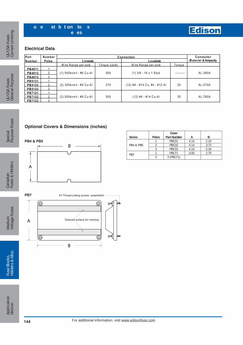
#4 Thread-cutting screws assembled
Textured surface for markingA
B
B
A
Electrical Data
Optional Covers & Dimensions (inches)
W ire R ange per po le T orque (Lb-In) W ire R ange per po le T orqueP B 4011 1P B 4012 2P B 4013 3P B 5121 1P B 5122 2P B 5123 3P B 7121 1P B 7122 2P B 7123 3
(12) #4 - #14 C u-A l500(2) 500kcm il - #6 C u-A l
(2 ) 300kcm il - #4 C u-A l 275 (12) #4 - #14 C u, #4 - #12 A l
A L-380A
A L-570A
A L-760A35
20
(1) 500kcm il - #6 C u-A l 500 (1) 3 /8 - 16 x 1 S tud ---------
P art N um ber
N um ber P o les
C onnector L ineside Loadside
C onnectionM ateria l & Ampacity
CoverSeries Poles Part Number A B
1 PBC31 4.14 2.10PB4 & PB5 2 PBC32 4.14 3.72
3 PBC33 4.14 5.34PB7 1 PBC71 3.00 2.75
3 3 (PBC71)
PB4 & PB5
PB7
144 For additional information, visit www.edisonfuse.com
Appl
icat
ion
Sect
ion
Fuse
Blo
cks,
Hold
ers
& M
isc.
Med
ium
Volta
ge F
uses
Cana
dian
Fuse
s &
Hold
ers
Spec
ial
Purp
ose
Fuse
sUL
/CSA
Fus
esGe
nera
l Pur
pose
UL/C
SA F
uses
Curr
ent L
imiti
ng
o e st b t on lo s e es

Circuit Protection
145
Medium
Voltage FusesUL/CSA FusesCurrent Lim
itingUL/CSA FusesGeneral Purpose
SpecialPurpose Fuses
CanadianFuses & Holders
ApplicationSection
Fuse Blocks,Holders & M
isc.
For additional information, visit www.edisonfuse.com
se Co e sn at n an on n at n
SAMI Features:• Innovative design, covers exposed terminals and contacts
of Edison fuse blocks.• Fits most competitive fuse blocks.• Light on indicating SAMI shows when the fuse is
open–helps troubleshoot the system and reduces downtime.
• All versions are reusable—no need to pay for indicationevery time a fuse opens.
• Indication contacts have teeth to break oxidation layer onthe existing fuse endcap to provide a clear signal path.
• Less than 0.6mA leakage current at 600 volt.• Visual marking of lineside and loadside.• SAMI cover ends can easily be trimmed if necessary, to
fit cover over existing wiring or to fit most safety switches.• Dead front construction provides added protection against
accidental contact by maintenance personnel.• Labels are provided with the SAMI fuse cover for writing
in circuit or fuse information.• One cover is required for each pole.
WARNING: To avoid electrical shock, turn poweroff before installing, removing or servicing.
For SAMI trimming guide specifications refer tothe following data sheet numbers:7008 - SAMI 1-9 Trimming Guides.
*Catalog NumbersFor Indicating Cover, add suffix I.For Non-indicating cover, add suffix N.Example: SAMI-7I = Indicating
SAMI-7N = Non-indicating
Indicating feature requires a minimum of 90Vac or115Vdc to illuminate lamp.
**UL Recoginized† SAMI-8A adapter available for small RK, K5, H bodydesign. SAMI-8N comes standard with adapter(SAMI-8A)
LINE
Bu
ss
SA
MI -2
LOA
D TEST PROBE TEST PROBE
C
B
A
FUSE
Catalog Number SAMI™ Series
Indicating Fuse Covers:SAMI™ Series: For Class J, RK1, RK5, H, K5, CC, G andmidget type fuses.
Operating Voltage:Non-Indicating - 0-600Vac/dcIndicating - 90 to 600Vac
- 115 to 600VdcAmp Rating: 0 - 100AAgency Approvals: UL Listed
CSA (Class 6225-01,File No. LR47235)
Material: Black Thermoplastic with a flammability rating of UL 94V2
Catalog Data (600V) Dimensional Data (inches)CatalogNumber Description A B C
SAMI-1600V, (0-30A) and250V, RK, K5, H (35-60A) 5.02 1.03 1.94
SAMI-2 600V, RK, K5, H (0-30A) 7.03 1.30 2.07
SAMI- 600V, (65-100A) 7.03 1.30 2.33
SAMI-4 250V, RK, K5, H (65-100A) 8.20 1.30 2.18
SAMI-5 600V, RK, K5, H (35-60A) 8.20 1.30 2.18
SAMI-6 600V, (35-60A) 4.98 1.17 2.14
SAMI- 600V, Midget 3.82 0.75 1.72
SAMI-8 600V, RK, K5, H (65-100A) 10.38 1.50 2.33
SAMI- 250V, RK, K5, H (0-30A) 3.82 0.75 1.72

HEB-For any 13⁄32" x 1 1⁄2" fuse.Fuse holder rated 30A,600V (CSA Listed 15Amax.). Typical fuse types:Edison MOL MEN, MEQand MCL. (1⁄10 -30A)
HET-A HEB- fuse holder with apermanently installed solidneutral. Easily identified bywhite plastic coupling nut.
Single-Pole13⁄32" x 1 1⁄2" Fuses
HEY-Double-pole fuse holder haswater-resistant, polarizeddesign, and accepts ClassCC branch circuit fuses(Edison fuse types EDCC,HCTR or HCLR, 600V orless) Particularly applicablein street lighting circuits withoptional breakawayreceptacle.
HEX-For any 13⁄32" x 1 1⁄2" fuse.Fuse holder rated 30A,600V (CSA Listed 15Amax.). Typical fuse types:Edison MOL MEN, MEQand MCL. (1⁄10 -30A)
Double-PoleClass CC 13⁄32" x 1 1⁄2" Midget Fuses
Packaging & Ordering Information:
HEB Load Side LineHET Terminal TerminalHEY A thru W A thru WHEX
XXX
Single- and Double-Pole without BreakawayOption
Packaging & Ordering Information:
HEB or Load Line Break-W-WayHET Terminal Terminal Terminal
A thru K RLC -A thru Jor RYC
XXX W
Single-Pole with Breakaway Option
Packaging & Ordering Information:
HEX or Load Line Break-W-WayHEY Terminal Terminal Terminal
A thru K DRLC -A thru Jor DRYC
XXX W
Double-Pole with Breakaway Option
A ailable art umber
on- ea a a n ts- - - C- - - - - -- - - - C --CC - - - - -- - - - -- - - .
en nfo at on ec gni ed Guide ile
C Certi ied Class - ile C
ea a a n tsncludes use h lder breakawa part and insulating b ts
- - - - C- - - C- - - C-C - - C- - - - - C - - C- - - C-- - C - - C- - - C - - C- - - C - - - - C- - -
en nfo at on ec gni ed Guide ile
C Certi ied Class - ile C
146 For additional information, visit www.edisonfuse.com
Appl
icat
ion
Sect
ion
Fuse
Blo
cks,
Hold
ers
& M
isc.
Med
ium
Volta
ge F
uses
Cana
dian
Fuse
s &
Hold
ers
Spec
ial
Purp
ose
Fuse
sUL
/CSA
Fus
esGe
nera
l Pur
pose
UL/C
SA F
uses
Curr
ent L
imiti
ng
n ne se ol e s fo an Class CC ses

Circuit Protection
147
Medium
Voltage FusesUL/CSA FusesCurrent Lim
itingUL/CSA FusesGeneral Purpose
SpecialPurpose Fuses
CanadianFuses & Holders
ApplicationSection
Fuse Blocks,Holders & M
isc.
For additional information, visit www.edisonfuse.com
n nese ol e s
Catalog and Specification DataNote: The construction elements listed below illustrate the fullconstruction of the available part numbers. NOT all construction elements are available in all combinations.
Conductor TerminalsConductor Data
TerminalSymbolsLoad Line
Type Terminal Size Side SideCopper Crimp 12 to 8 1 A A12 2
10 26 1 B B4 18 2 C C4 1 —6 2 D D2 1 —4 2 E E
Copper Set-Screw
12 to 2 1
12 to 2 2 K K
Solid Breakaway (Re uired with W WBreakawayReceptacle)
A ailable art umber
Serie- - - C - - -- -CC - - and - .
en nfo at on ec gni ed Guide ile
C Certi ied Class - ile
Serie- - - C - - -- and - .
Serie- - - - and -
Catalog Data — Insulating BootsCatalogNumbers Type
2A0660 Single Conductor
2A0661 Two Conductor
Insulating boots are optional and not included withnon-Breakaway holders and must be ordered separately.They are included as a standard item with the breakawayseries. When boots are utilized, extra heat retention requiresthat fuses are sized at a minimum of 200% of the RMSload current.
No. P
erTe
rmin
al
Solid
Stra
nded
OptionalConductor Data
BreakawayTerminalSingle- Double-
Type Terminal Size Pole PoleCopper Crimp #12 to #8 1 • • -RLC-A -DRLC-A
#6 1 • • -RLC-B -DRLC-B
#4 1 • • -RLC-C -DRLC-C
Copper Set-Screw
#12 to #2 1 • • -RLC-J -DRLC-J
#12 to #2 2 • •` -RYC -DRYC
* Terminal illustrations show the end view of single-pole receptacles and one-pole only ofthe double-pole receptacles. Thus, for example, in the case of a double-pole, set-screwtype receptacle with terminals that accept two conductors, a total of four conductors couldbe connected to the receptacle per the following drawing.
No. P
erTe
rmin
al
Solid
Stra
nded
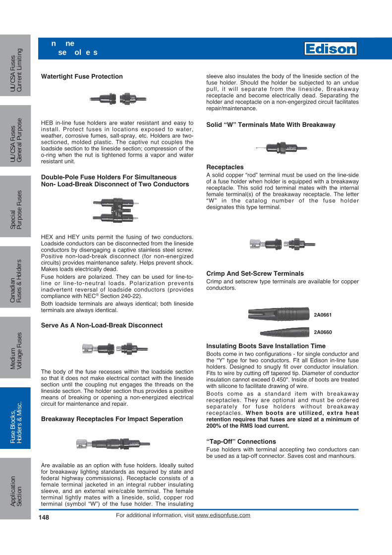
Watertight Fuse Protection
HEB in-line fuse holders are water resistant and easy toinstall. Protect fuses in locations exposed to water,weather, corrosive fumes, salt-spray, etc. Holders are two-sectioned, molded plastic. The captive nut couples theloadside section to the lineside section; compression of theo-ring when the nut is tightened forms a vapor and waterresistant unit.
Double-Pole Fuse Holders For SimultaneousNon- Load-Break Disconnect of Two Conductors
HEX and HEY units permit the fusing of two conductors.Loadside conductors can be disconnected from the linesideconductors by disengaging a captive stainless steel screw.Positive non-load-break disconnect (for non-energizedcircuits) provides maintenance safety. Helps prevent shock.Makes loads electrically dead.Fuse holders are polarized. They can be used for line-to-l ine or l ine-to-neutral loads. Polarization preventsinadvertent reversal of loadside conductors (providescompliance with NEC® Section 240-22).Both loadside terminals are always identical; both linesideterminals are always identical.
Serve As A Non-Load-Break Disconnect
The body of the fuse recesses within the loadside sectionso that it does not make electrical contact with the linesidesection until the coupling nut engages the threads on thelineside section. The holder section thus provides a positivemeans of breaking or opening a non-energized electricalcircuit for maintenance and repair.
Breakaway Receptacles For Impact Seperation
Are available as an option with fuse holders. Ideally suitedfor breakaway lighting standards as required by state andfederal highway commissions). Receptacle consists of afemale terminal jacketed in an integral rubber insulatingsleeve, and an external wire/cable terminal. The femaleterminal tightly mates with a lineside, solid, copper rodterminal (symbol “W”) of the fuse holder. The insulating
sleeve also insulates the body of the lineside section of thefuse holder. Should the holder be subjected to an unduepull, i t wil l separate from the l ineside, Breakawayreceptacle and become electrically dead. Separating theholder and receptacle on a non-engergized circuit facilitatesrepair/maintenance.
Solid “W” Terminals Mate With Breakaway
ReceptaclesA solid copper “rod” terminal must be used on the line-sideof a fuse holder when holder is equipped with a breakawayreceptacle. This solid rod terminal mates with the internalfemale terminal(s) of the breakaway receptacle. The letter“W” in the catalog number of the fuse holderdesignates this type terminal.
Crimp And Set-Screw TerminalsCrimp and setscrew type terminals are available for copperconductors.
Insulating Boots Save Installation TimeBoots come in two configurations - for single conductor andthe “Y” type for two conductors. Fit all Edison in-line fuseholders. Designed to snugly fit over conductor insulation.Fits to wire by cutting off tapered tip. Diameter of conductorinsulation cannot exceed 0.450". Inside of boots are treatedwith silicone to facilitate drawing of wire.Boots come as a standard item with breakawayreceptacles. They are optional and must be orderedseparately for fuse holders without breakawayreceptacles. When boots are utilized, extra heatretention requires that fuses are sized at a minimum of200% of the RMS load current.
“Tap-Off” ConnectionsFuse holders with terminal accepting two conductors canbe used as a tap-off connector. Saves cost and manhours.
2A0661
2A0660
148 For additional information, visit www.edisonfuse.com
Appl
icat
ion
Sect
ion
Fuse
Blo
cks,
Hold
ers
& M
isc.
Med
ium
Volta
ge F
uses
Cana
dian
Fuse
s &
Hold
ers
Spec
ial
Purp
ose
Fuse
sUL
/CSA
Fus
esGe
nera
l Pur
pose
UL/C
SA F
uses
Curr
ent L
imiti
ng
n nese ol e s

Circuit Protection
149
Medium
Voltage FusesUL/CSA FusesCurrent Lim
itingUL/CSA FusesGeneral Purpose
SpecialPurpose Fuses
CanadianFuses & Holders
ApplicationSection
Fuse Blocks,Holders & M
isc.
For additional information, visit www.edisonfuse.com
anel o nt ann ne se ol e s
Catalog Number HKP,HKP-HH, and HKP-W
Standard Fuse Holders:For use with 1⁄4" x 1 1⁄4" fuses (Edison type ABC, AGC, MDL, MDAetc.)
Terminals: Bayonet-type knob.Vibration resistant.For panels up to 5⁄16"(7.9mm) thick.
Agency Approvals:UL Recognized, Guide IZLT2,File E14853CSA Certified, Class 6225-01,File 47235
Electrical Ratings for HPF SeriesCatalogNumber Amps Volts Fuse Description
HKP 30 250 —
HKP-HH 15 250 HKP with 1/4"Quick-connectterminal
HKP-W 30 250 HKP with drip-proof knob.
Catalog Number HPF
Standard Fuse Holders WithScrew-Type Knob:For use with 13⁄32" x 1 5⁄16" to 1 1⁄2" fuses.
Agency Approvals:UL Recognized, Guide IZLT8,File E14853, cURusUL 94V0 Flammability Rating
Electrical RatingsCatalogNumber Amps Volts Fuse Description
HPF 30 600 1 1/2" (38.1mm)MOL, MEN, MCL
HPF-L 5 600 EBS, 13/32" x 1 3/8"fuses
HPF-EE 15 480 SEC 0-15,13/32" x 1 3/8" fuses
HPF-JJ 20 480 SEC 20,13/32” x 1 13/32" fuses
HPF-FF* 30 300 SEC 25 & 30,13/32" x 1 5/8" fuses
HPF-RR 30 600 HCLR, HCTR & EDCC Class CC fuses
HPF-WT 30 600 Splash-proof knobfor 1 1/2" fuses
*No CSA Certification.
0.78"
0.69"
2.44"Max
0.505" + 0.005"(12.8mm + 0.13mm)
0.473" + 0.005"(12.0mm + 0.13mm)
Punched Mounting Hole
FU
SE FUS
E
FUSE
1.031" + 0.003"(26.2mm + 0.08mm)
0.187" + 0.002"(4.75mm + 0.05mm)
Mounting HoleFlange Rear of Panel
Mounting HoleFlange Front of Panel
0.890" + 0.003"(22.6mm + 0.08mm)
1.312" + 0.003"(33.3mm + 0.08mm)
1.312" + 0.003"(33.3mm + 0.08mm)
0.180" DIA.(4.6mm)
1.125"(28.6mm)
1.00"(25.4mm)
Without Fuse
2.69"(68.3mm)
0.88"(22.2mm)
1.78"(45.2mm)
1.31"(33.3mm)
2.81"(71.4mm)
With FuseDimensions - in (mm)
Dimensions - in (mm)
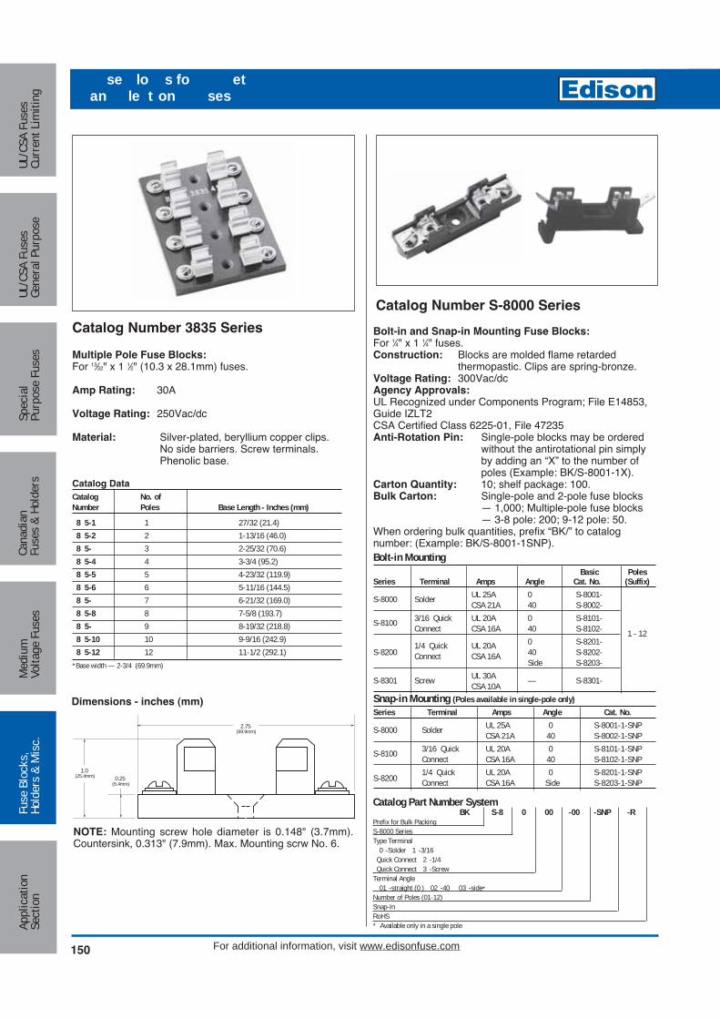
Catalog Number 3835 Series
Multiple Pole Fuse Blocks:For 13⁄32" x 1 1⁄2" (10.3 x 28.1mm) fuses.
Amp Rating: 30A
Voltage Rating: 250Vac/dc
Material: Silver-plated, beryllium copper clips.No side barriers. Screw terminals.Phenolic base.
Catalog Data Catalog No. ofNumber Poles Base Length - Inches (mm)
8 5-1 1 27/32 (21.4)8 5-2 2 1-13/16 (46.0)8 5- 3 2-25/32 (70.6)8 5-4 4 3-3/4 (95.2)8 5-5 5 4-23/32 (119.9)8 5-6 6 5-11/16 (144.5)8 5- 7 6-21/32 (169.0)8 5-8 8 7-5/8 (193.7)8 5- 9 8-19/32 (218.8)8 5-10 10 9-9/16 (242.9)8 5-12 12 11-1/2 (292.1)
*Base width — 2-3/4 (69.9mm)
Catalog Number S-8000 Series
Bolt-in and Snap-in Mounting Fuse Blocks:For 1⁄4" x 1 1⁄4" fuses.Construction: Blocks are molded flame retarded
thermopastic. Clips are spring-bronze.Voltage Rating: 300Vac/dcAgency Approvals:UL Recognized under Components Program; File E14853,Guide IZLT2CSA Certified Class 6225-01, File 47235Anti-Rotation Pin: Single-pole blocks may be ordered
without the antirotational pin simplyby adding an “X” to the number ofpoles (Example: BK/S-8001-1X).
Carton Quantity: 10; shelf package: 100.Bulk Carton: Single-pole and 2-pole fuse blocks
— 1,000; Multiple-pole fuse blocks— 3-8 pole: 200; 9-12 pole: 50.
When ordering bulk quantities, prefix “BK/” to catalognumber: (Example: BK/S-8001-1SNP).Bolt-in Mounting
Basic PolesSeries Terminal Amps Angle Cat. No. (Suffix)
S-8000 Solder UL 25A 0 S-8001-CSA 21A 40 S-8002-
S-8100 3/16 Quick UL 20A 0 S-8101-Connect CSA 16A 40 S-8102- 1 - 121/4 Quick UL 20A 0 S-8201-
S-8200 Connect CSA 16A 40 S-8202-Side S-8203-
S-8301 Screw UL 30A — S-8301-CSA 10ASnap-in Mounting (Poles available in single-pole only)Series Terminal Amps Angle Cat. No.
S-8000 Solder UL 25A 0 S-8001-1-SNPCSA 21A 40 S-8002-1-SNP
S-8100 3/16 Quick UL 20A 0 S-8101-1-SNPConnect CSA 16A 40 S-8102-1-SNP1/4 Quick UL 20A 0 S-8201-1-SNPS-8200 Connect CSA 16A Side S-8203-1-SNP0.25
(6.4mm)
1.0(25.4mm)
2.75(69.9mm)
NOTE: Mounting screw hole diameter is 0.148" (3.7mm).Countersink, 0.313" (7.9mm). Max. Mounting scrw No. 6.
Dimensions - inches (mm)
Catalog Part Number SystemBK S-8 0 00 -00 -SNP -R
Prefix for Bulk PackingS-8000 SeriesType Terminal
0 -Solder 1 -3/16 Quick Connect 2 -1/4Quick Connect 3 -Screw
Terminal Angle01 -straight (0 ) 02 -40 03 -side*
Number of Poles (01-12)Snap-InRoHS* Available only in a single pole
150 For additional information, visit www.edisonfuse.com
Appl
icat
ion
Sect
ion
Fuse
Blo
cks,
Hold
ers
& M
isc.
Med
ium
Volta
ge F
uses
Cana
dian
Fuse
s &
Hold
ers
Spec
ial
Purp
ose
Fuse
sUL
/CSA
Fus
esGe
nera
l Pur
pose
UL/C
SA F
uses
Curr
ent L
imiti
ng
se lo s fo etan le t on ses
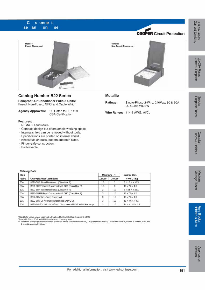
Circuit Protection
151
Medium
Voltage FusesUL/CSA FusesCurrent Lim
itingUL/CSA FusesGeneral Purpose
SpecialPurpose Fuses
CanadianFuses & Holders
ApplicationSection
Fuse Blocks,Holders & M
isc.
For additional information, visit www.edisonfuse.com
C s onne tse an on se
MetallicFused Disconnect
MetallicNon-Fused Disconnect
Metallic
Ratings: Single-Phase 2-Wire, 240Vac, 30 & 60AUL Guide WGEW
Wire Range: #14-3 AWG, Al/Cu
Catalog Number B22 SeriesRainproof Air Conditioner Pullout Units:Fused, Non-Fused, GFCI and Cable Whip.
Agency Approvals: UL Listed to UL 1429CSA Certification
Features:• NEMA 3R enclosure.• Compact design but offers ample working space.• Internal shield can be removed without tools.• Specifications are printed on internal shield.• Knockouts on back, bottom and both sides.• Finger-safe construction.• Padlockable.
Catalog DataMain Maximum P1 Approx. Dim.Rating Catalog Number Description 120Vac 240Vac x W x D (in.)30A B221-30F* Fused Disconnect (Class H or R) 1.5 3 8 3⁄4 x 5 3⁄8 x 32 7⁄830A B221-30FGF Fused Disconnect with GFCI (Class H or R) 1.5 3 13 x 7 1⁄2 x 4 3⁄460A B222-60F* Fused Disconnect (Class H or R) 3 10 8 3⁄4 x 5 3⁄8 x 32 7⁄860A B222-60FGF Fused Disconnect with GFCI (Class H or R) 3 10 13 x 7 1⁄2 x 4 3⁄460A B222-60NF Non-fused Disconnect 3 10 13 x 7 1⁄2 x 4 3⁄460A B222-60NFGF Non-fused Disconnect with GFCI 3 10 11 3⁄4 x 6 1⁄2 x 4 1⁄260A B222-60NFG12W** Non-fused Disconnect with 1/2 inch Cable Whip 3 10 14 3⁄4 x 12 1⁄2 x 4.5
*Suitable for use as service equipment with optional field installed lug kit number B-DPOG.1Rated with Edison ECNR and LENRK dual-element time-delay fuses.** Maximum 30 amp upstream overcurrent protection device, 1⁄2 inch harness device, 10 ground hot wire si e, 10 flexible wire si e, six feet of conduit, 1-90 and
1- straight non-metallic fitting.

Fuses Reducers for Class H, J, K, & R Fuses
Agency Approvals: UL Listed,Guide #IZZR, File #E12853
CSA Certified, Class 6225-01, File 47235
Features:• Fuse reducers install on fuses and permit smaller size
fuses to be used in larger amp size switches and blocks.• Reducers will fit into any panel or switch including the
dead-front type.• Strong contact is maintained both mechanically and
electrically.• UL Listed.• There are no reducers to go from 250V to 600V.• There are no reducers for switching from one fuse class to
another.• There are no reducers for Class T or Class L fuses.
Fuse Reducers for Class H & K Dimension Fuses KON, ERN, PONC, CDNC; KOS, ERS, CDSC
Catalog No. (Pairs)
250V 600VFuse Desired Reducer ReducerSize Size No. No.
30A 60A No. 263 No. 663
30A 100A No. 213 No. 216
60A 100A No. 216 No. 616
60A 200A No. 226 No. 626
100A 200A No. 2621 No. 2621
100A 400A *No. 2641 *No. 2641
200A 400A No. 2642 No. 2642
100A 600A *No. 2661 *No. 2661
200A 600A *No. 2662 *No. 2662
400A 600A *No. 2664 *No. 2664
* Product does not have CSA certification.
Fuse Reducers for Class J Dimension Fuses- JDL, JFL, & CJ
Catalog No. (Pairs)
Fuse Desired Reducer Size Size No.
30A 60A **J-63
30A 100A **J-13
60A 100A **J-16
60A 200A **J-26
100A †200A **J-21
100A †400A **J-41
200A †400A **J-42
200A 600A **J-62
400A †600A **J-64
† Not for Bolt-on Applications.
** Product does not have UL or CSA certification.
Fuse Reducers for Class R Dimension FusesECNR, LENRK, NCLR; ECSR, LESRK, & SCLR
Catalog No. (Pairs)
250V 600VFuse Desired Reducer ReducerSize Size No. No.
30A 60A No. 263-R No. 663-R
30A 100A No. 213-R No. 216-R
60A No. 216-R No. 616-R
60A 200A No. 226-R No. 626-R
100A *No. 2621-R
100A 400A *No. 2641-R
200A *No. 242-R *No. 642-R
100A *No. 2661-R
200A 600A *No. 2662-R
400A **No. 2664-R
* Product does not have CSA certification.
**Single reducer only (pair not required)
Note: Carton quantity - 10 pair.
152 For additional information, visit www.edisonfuse.com
Appl
icat
ion
Sect
ion
Fuse
Blo
cks,
Hold
ers
& M
isc.
Med
ium
Volta
ge F
uses
Cana
dian
Fuse
s &
Hold
ers
Spec
ial
Purp
ose
Fuse
sUL
/CSA
Fus
esGe
nera
l Pur
pose
UL/C
SA F
uses
Curr
ent L
imiti
ng
se e e sClass an
CROSS REFERENCENEW OLDEDISON EDISON GOULD LITTELFUSENo. 263 38632 None LRU263MNo. 213 38132 H1032 LRU213MNo. 216 38162 H1062 LRU216No. 226 38262 None NoneNo. 663 38636 None LRU663MNo. 616 38166 H1066 LRU616No. 626 38266 None NoneNo. 2621 38212 None LRU2621No. 2641 2641E None NoneNo. 2642 38422 None LRU2642No. 2661 2661E None NoneNo. 2662 2662E None NoneNo. 2664 38642 None None

Circuit Protection
153
Medium
Voltage FusesUL/CSA FusesCurrent Lim
itingUL/CSA FusesGeneral Purpose
SpecialPurpose Fuses
CanadianFuses & Holders
ApplicationSection
Fuse Blocks,Holders & M
isc.
For additional information, visit www.edisonfuse.com
se esso es
Catalog Number SFC-FUSE-CABSpare Fuse Cabinet
Size: 24 wide x 30 high x 12 deep
FEATURES:• Sturdy storage cabinet construction holds spare fuses.• Cabinet door equipped with locking handle.• Durable baked ASA 61 grey enamel.• Mounting holes with key slot 16-inches on center.
Extra shelf for spare fuse cabinet
Fuse pullers
FP-4 FP-3 FP-2 FP-6 FP-A3
Catalog Data Catalog For Fuse CartonNumber Diameter Qty. Fuse Type
FP-2 13/32 to 13/16 10 0 – 60A, 250V0 – 30A, 600V
FP- 1 to 1 3/4 10 70 – 200A, 250V35 – 200A, 600V
FP-4 1 3/4 to 2 1/2 1 225 – 600A, 250V225 – 400A, 600V
FP-6 13/32 to 13/16 1 Class T Fuses0 – 60A, 300/600V
FP-A 1/4 diameter and 10 Electronic glassautomotive blade fuses and blade type
Fuse Clip-Clamps
Catalog Data Clamp Size Weight
Volts Amps Cat. No. Ctn. Qty. Lbs. Kg.
250 0-30A No. 1 12 0.66 .3035-60A No. 2 12 0.96 .44
600 0-30A No. 2 12 0.96 .4435-60A No. 4 12 1.44 .6570-100A No. 5 12 1.20 .54
250 110-200A No. 6 6 1.26 .57or 225-400A No. 7 6 1.86 .84600450-600A No. 8 6 2.52 1.14
Catalog Number SFC-SHELF
CROSS REFERENCENEW EDISON OLD EDISONFP-2 38072FP-3 38073FP-4 38074
CROSS REFERENCENEW EDISON OLD EDISON LITTELFUSENo. 1 38001 LCC1No. 2 38002 LCC2No. 4 38004 LCC4No. 5 38005 LCC5No. 6 38006 LCC6No. 7 38007 LCC7No. 8 38008 LCC8

154 For additional information, visit www.edisonfuse.com
le ents of a a t al se e f at on
General:The contractor shall install UL “Listed” fuses of the correctUL Class, type and ampere ratings in switches or place inspare fuses cabinet(s) as indicated on the plans and/or asspecified below. All installed and spare fuses shall be intheir original new, clean, dry and unused condition wheninstalled and when placed in a spare fuses cabinet(s). Thecontractor shall thoroughly clean, mechanically check andelectrically test, as required, all equipment and componentsbefore installing fuses and energizing.
UL Class L bolt-on fuses rated 601 to6000A:To mount UL Class L fuse types and amps ratings asshown on the plans, use stainless steel bolts of correctnumber, diameter and length, stainless steel spring washerson each side of the bolt and stainless steel nuts. The nutsshall be tightened to the torque recommended by ASTMStandards for the bolt size used. The bolts shall have thelargest diameter that will fit the bolt holes and length toallow full nut thread engagement. Bolts shall be installed ineach fuse mounting hole or slot. Class L fuses shall havesilver links. The quality benchmark for Class L fuses shallbe Edison Fusegear Catalog Symbol LCL time-delay type orCatalog Symbol LCU fast-acting type as shown on theplans. Edison Class L fuses are quality engineered andconstructed, using Statistical Process Control, for foolprooffiller retention without “O” rings, and do not expel gases.
UL Class R fuses rated up to 600A:UL Class RK1 dual element, time-delay fuse type and rat-ings shall be installed in Class R switches as shown on theplans. Class RK1 dual element fuses shall not use springsin the overload elements in ratings 70A and larger; theyshall have non-ferrous end caps for energy efficiency. Thequality benchmark for Class RK1 dual element fuses shallbe Edison Catalog Symbol LENRK(AMP)(250V) orLESRK(AMP) (600V).
UL Class J fuses rated up to 600A and300V Class T fuses rated 35 to 800A:Protection of circuit breakers requires the use of Class J orClass T fuses as shown on the plans. These fuse Classesare not interchangeable with fuses having less current limit-ing ability. The quality benchmark for these fuses shall beEdison Catalog Symbol JFL (Class J fast acting type) orCatalog Symbol TJN (300V Class T fast acting type).
Fuse classes, types and ratings:All fuses have been specified as to UL Class, type, voltsand amp rating on the plans when the project wasengineered. No fuse types or ratings will be changed in thefield without approval from the project design engineer.Generally, the fuse types commonly specified are Class Ltime-delay type, Class RK1 dual element type and Class Jfast-acting type. Class L fast-acting, Class RK1 fast-actingand 300V Class T fast-acting fuses may be specified forspecial conditions.
Interchangeability of specified fuses:The fuse brand specified is the quality benchmark and ispreferred. All installed and spare fuses shall be both electri-cally and physically interchangeable with the same specificClasses, types and ratings of any other brand of fuses thatare UL “Listed” per the appropriate UL Standard for safetywithout creating a safety hazard for the public and/or build-ing occupants. Otherwise, a fuse-protected power distribu-tion system design can not meet the requirements of goodengineering practice, as applied during the design of thisproject, and can not meet the requirements of the NationalElectrical Code® during the life of the installation. Thecontractor shall place an instruction label inside the door ofeach switch (do not cover other instructions) identifying theUL Class, Type, Volts and Amp rating of originally installedfuses.
Spare fuses:A metal spare fuse cabinet(s) shall be provided as required,surface mounted, with lockable handle. 10% of each typeand rating of installed fuses shall be duplicated as sparefuses, or a minimum of 3 fuses of each type and rating, andplaced in a Edison Catalog Symbol ESFC spare fusecabinet(s) and locked.
Engineering plans and specifications:A copy of the pertinent sheets of the plans and the pages ofspecifications pertaining specifically to installed fusesinformation shall be placed inside one of the Edison CatalogSymbol spare fuse cabinets for maintenance referencepurposes.
Low Voltage (600V or Less) Fuse Specification:
Appl
icat
ion
Sect
ion
Fuse
Blo
cks,
Hold
ers
& M
isc.
Med
ium
Volta
ge F
uses
Cana
dian
Fuse
s &
Hold
ers
Spec
ial
Purp
ose
Fuse
sUL
/CSA
Fus
esGe
nera
l Pur
pose
UL/C
SA F
uses
Curr
ent L
imiti
ng

Circuit Protection
155
Medium
Voltage FusesUL/CSA FusesCurrent Lim
itingUL/CSA FusesGeneral Purpose
SpecialPurpose Fuses
CanadianFuses & Holders
ApplicationSection
Fuse Blocks,Holders & M
isc.
se Te nolo
Ambient Temperature*The temperature of the air surrounding the fuse.
Arcing TimeThe amount of time that passes from the instant the fuse ele-ment or link has melted until the overcurrent is interrupted orcleared.
Asymmetrical CurrentRefer to ALTERNATING CURRENT. A-C current is asymmetri-cal when the loops about a zero axis are unequal (offset). Thiscondition is usually associated with the first five or less cyclesof fault current flow in a circuit that has inductive reactance. Allpower distribution systems have a variable amount of inductivereactance.
Body*The part of the fuse which encloses the fuse elements and sup-ports the contacts. Also referred to as cartridge, tube or case.
Bolted FaultThis refers to a zero impedance fault considered at locations ina power system where the maximum value of available faultcurrent is calculated.
BridgeThe specially designed narrow portion of a fuse link that heatsfastest under overcurrent conditions to open first.
Cartridge Fuse*A fuse consisting of a current responsive element inside a fusebody with contacts on both ends.
Cartridge Size*The range of voltage and ampere ratings assigned to a car-tridge of specific dimensions and shape.
Clearing I2t (Ampere Squared Seconds)*The measure of heat energy developed as a result of currentflow between the time that current begins to flow and until thefuse clears the circuit. “I2” stands for the square of the effectivelet-through current and “t” stands for the time of current flow inseconds. The term I2t also applies during the melting or arcingportions of the clearing time and is referred to as melting or arc-ing I2t respectively. Clearing I2t is the sum of melting I2t andarcing I2t.
Clearing TimeThis is the total opening time of a fuse from the occurrence ofan overcurrent until the fuse stops current flow. This is the sumof link melting and arcing time.
Contacts*The external metallic parts of the fuse used to complete the cir-cuit. Also referred to as ferrules, caps, blades or terminals.
Current LimitationA fuse provides current limitation when the link melts undershort-circuit conditions to interrupt the current flow before thepeak of the first one-half cycle of prospective current and thecurrent flow is stopped within one-half cycle.
Current-Limiting Fuse*A fuse that meets the following three conditions: 1) interrupts allavailable overcurrents within its interrupting rating; 2) within itscurrent-limiting range, limits the clearing time at rated voltage toan interval equal to, or less than, the first major or symmetricalcurrent loop duration; and 3) limits peak let-through current to avalue less than the available peak current.
Current-Limiting Range*A range of available currents from the threshold current to theinterrupting current rating of a fuse.
Current Rating*The A-C or D-C ampere rating which the fuse is capable of car-rying continuously under specified conditions.
DelayThis refers to intentional “delay” designed into the overloadrange operation of a fuse and is meaningless except as definedby a fuse manufacturer. Other words used to indicate delay butnot UL defined may be “Time-Lag”, “Delay Type”, etc..
Dual Element FuseThe words “Dual Element” and “Time-Delay” appear on thelabels of Class R fuses to indicate that the fuse has UL defineddelay in the overload operation range of a minimum of 10 sec-onds at 500% of the fuse amperes rating. A “Dual Element”fuse has separate overload and short-circuit elements and isconsidered a “true time-delay fuse” design as opposed to othertypes of construction to obtain delay.
Effective Current (Ie)“Effective” and “RMS” both refer to the heating effect value ofan A-C current equivalent to a steady flow of a D-C current.“Effective let-through amperes” (Ie) refers to the heating effectvalue of the current allowed to flow during the clearing of ashort-circuit current.
Eutectic AlloyThis is an alloy of lead, tin and other metals that, by metallurgi-cal definition, changes from a solid directly to a liquid when itsmelting point is reached. This alloy is used in Edison Class Rfuses for dependable overload element operation.
Fast-Acting FuseThis is a fuse with no intentional time-delay designed into theoverload range. Sometimes referred to as a “single elementfuse” or “non-delay fuse”.
Fault CurrentShort-circuit current that flows partially or entirely outside theintended normal load current path of a circuit or component.Values may be from hundreds to many thousands of amperes.
FerruleThe cylindrical brass, bronze or copper mounting terminals offuses with amps ratings up to 60 amperes. The cylindrical ter-minals at each end of a fuse fit into fuse clips.
Filler*A material used to fill a section or sections of a fuse which aidsin arc extinction.
Fuse*A protective device which opens by the melting of a currentsensitive element during specified overcurrent conditions.
Heat SinkA mass of metal, usually copper or a eutectic alloy, used in theoverload element of Class R fuses to provide accurate timedelay by absorbing heat from an overload current flow througha fuse.
High Rupturing Capacity (HRC)HRC is used by Canadian and British Standards as an equiva-lent to the U.S. interrupting rating of a fuse. HRC must be atleast 100,000 amperes.
*From ANSI/ NEMA FU1-86
For additional information, visit www.edisonfuse.com

156
se Te nolo
For additional information, visit www.edisonfuse.com
Appl
icat
ion
Sect
ion
Fuse
Blo
cks,
Hold
ers
& M
isc.
Med
ium
Volta
ge F
uses
Cana
dian
Fuse
s &
Hold
ers
Spec
ial
Purp
ose
Fuse
sUL
/CSA
Fus
esGe
nera
l Pur
pose
UL/C
SA F
uses
Curr
ent L
imiti
ng
I2t (Amperes Squared Seconds)This is a value obtained by multiplying an effective currentsquared by the time of flow of the current in seconds. It is not aheat energy value, but represents heat energy for comparisonpurposes. Some common uses are to determine fuse selectivityand to select current limiting fuses that will limit this value to becompatible with the withstandability of semi-conductors thathave n I2t rating.
Interrupting Rating*A rating based upon the highest rms alternating current ordirect current which the fuse is required to interrupt under spe-cific conditions.
Knife BladeA flat copper mounting blade (terminal) at each end of fusesrated 70 through 6000 amperes. Knife blades may be mountedin fuse clips or bolted in place via blade holes, depending onthe fuse type.
LimiterLimiters have internal construction like fuses but provide onlyshort-circuit protection and no overload protection. They areintended for special applications such as Cable Limiters andWelder Limiters.
LinkThe fusible portion of the fuse which melts, or reacts by othermeans, to clear the circuit during an overcurrent condition. Alsoreferred to as an element.
Magnetic StressWhen thousands of amps of short-circuit current flows throughequipment and conductors, strong magnetic fields are devel-oped that may cause serious damage unless adequate physicalbracing is applied. Force is proportional to the value of peakcurrent squared. This force is usually reduced by current limit-ing fuses as compared to other overcurrent protective devices.
Maximum Energy*A condition under which, in a specified time, the maximumamount of heat possible is generated in the fuse before clear-ing.
Melting Time*The time from the initiation of an overcurrent to the instant arc-ing begins inside a fuse.
Nonrenewable Fuse*A fuse which cannot be restored for service after operation.
Normal Frequency Recovery Voltage*The normal frequency rms voltage impressed upon the fuseafter the circuit has been interrupted and after high frequencytransients have subsided.
One-Line DiagramAn electrical diagram that shows one line to represent two ormore conductors for simplification.
One-Time FuseA term used to identify a non-renewable Class H fuse asopposed to a Class H fuse with replaceable Iinks. See “non-renewable fuse”.
Overcurrent*Any current in excess of the fuse current rating.
OverloadA value of overcurrent usually considered to be up to about 10times the ampere rating of an overcurrent protection device orcircuit ampere rating.
Peak Arc Voltage*The maximum peak voltage across the fuse during the arcingtime.
Peak Let-Through Current (Ip)*The maximum instantaneous current through a fuse duringinterruption in its current-limiting range.
Rating*A designated limit of operating characteristics based on definiteconditions.
Rejection Feature*The physical characteristic of a fuse and fuseholder (slot,groove pin or overall dimension) which prevents substitution byother classes of fuses.
Renewable Fuse*A fuse which can be readily restored for service after operationby the replacement of the renewal elements.
Renewal Element (Renewal Link)*That part of a renewable fuse that is replaced after each inter-ruption to restore the fuse to operating condition.
Short-Circuit Current Refer to Fault Current.
Single-Element Fuse Refer to Fast-Acting Fuse.
Supplemental Fuse (UL)A UL fuse class per Standard 198G that defines certain smallfuses not intended for branch circuit protection.
Thermal StressHeat builds up in equipment and conductors during the time ofovercurrent flow that may cause thermal stress and potentialthermal (heat) damage if overcurrent protection devices do notoperate fast enough.
Threshold Current*The minimum rms symmetrical available current of the current-limiting range, where melting of the fuse element occurs atapproximately 90 degrees on the symmetrical current wave,and total clearing time is less than one-half cycle.
Threshold Ratio*The threshold current divided by the fuse current rating.
Time-Delay Fuse*A fuse capable of carrying a specific overcurrent for a minimumtime.
Total Clearing Time*Refer to Clearing Time.
Voltage Rating*The maximum rms ac voltage or the maximum dc voltage atwhich the fuse is designed to operate.
*From ANSI/NEMA FU1-86

Circuit Protection
157
Medium
Voltage FusesUL/CSA FusesCurrent Lim
itingUL/CSA FusesGeneral Purpose
SpecialPurpose Fuses
CanadianFuses & Holders
ApplicationSection
Fuse Blocks,Holders & M
isc.
For additional information, visit www.edisonfuse.com
C oss efe en e
CROSS REFERENCE GUIDEBRUSH/ GEC/
VOLT EDISON DORMAN CEFCO GOULD LITTELFSE. FUSETEK SIEMENS NORAM AEROFLEXUL CLASS CURRENT LIMITING FUSES (CSA CLASS)RK1 Fast Acting 250 NCLR NCLR C-HG A2KR, HNR KLNR RHN — — HB(HRCI-R) 600 SCLR SCLR C-HR A6KR, HSR KLSR RHS — — HARK1 Time Delay 250 LENRK LENRK LON-RK A2D-R LLNRK — — 2R-D —(HRCI-R) 600 LESRK LESRK LOS-RK A6D-R LLSRK — — 6R-D —RK5 Time Delay 250 ECNR ECNR CRNR TRNR, TR FLN-R RDN — — —(HRCI-R) 600 ECSR ECSR NRSR TRSR,TRS FLS-R IDSR RDS — — —L Fast Acting 600 LCU LCU CL, CLU A4BQ — LFA — 6L-F L8, L12(HRCI-L) Time Delay 600 LCL LCL CLL A4BY,A4BT KLPC, KLLU — — 6L-D L16, L20J Fast Acting 600 JFL JCL, CJ C-J A4J, CJ JLS JFC 3NW2-71- 6J-F JA(HRCI-J) Time Delay 600 JDL — — AJT JTD — — J-D —T Fast Acting 300 TJN TJN — A3T JLLN — — — —(HRCI-T) 600 TJS TJS — A6T JLLS — — — —G Time Delay 480 SEC — — AG5 SLC — — — —CC Time Delay 600 EDCC — — ATDR CCMR — — 6M-S —(HRCI-CC) Time Delay 600 HCTR — — ATQR KLDR — — 6CC-S —
Fast Acting 600 HCLR HCLR CTK-R ATMR KLKR FLKR — 6CC-F —UL CLASS GENERAL PURPOSE FUSESH Fast Acting 250 KON KON 50KOTN OTN NLN OFN — — —and K5 600 KOS KOS 50KOTS OTS NLS OFS — — —H Time Lag 250 ERN ERN — RFN RLN — — — —Renewable 600 ERS ERS — RFS RLS — — — —H Fuse Links 250 ELNE ELN — RLN LKN — — — —Renewable 600 ELS ELS — RLS LKS — — — —
600 MCL MCL CTK ATM KLK FLK — 6M-S —Midget Fast Acting 600 EBS EBS — SBS BLS — — 6N-F —
250 MOL MOL — OTM BLF FLF — — —500 MEQ MEQ — ATQ FLQ — — — —
Midget Time Delay 250 MEN MEN — TRM FLM FRM — — —125/250 MID MID — GFN FLA — — — —
CANADIAN FUSESCode/ One Time 250 KON/PONC KON/PON 50KOTN NRN OTN NLN OFN — — —Standard 600 KOS KOS 50KOTS NRS OTS NLS OFS — — —10K AIR Time Delay 250 CDNC CDN — CRN FLN ODN — — —
600 CDSC CDS — CRS FLS ODS — — —TYPE K Offset CIH07 CIH07 C-K ESK — — — — —Class C Blade 600 CIK07 CIK07 C-K ESK — — — — —
CIL14 CIL14 C-K ESK — — — — —HRCI-CA Fast Acting 600 CIF21 CIF21 C-N MS — — 3NWOMFS2 6CA-F —HRCI-CB Fast Acting 600 CIF06 CIF06/NK CNS GNS — NIC 3NWOMFS1 6CB-F —
EK EK CES — — — — — —HRC-II FUSES
Offset H07C H07C, AAO CIA FES,GIA — 2CO 3NW2-11 6C-F 932Blade 600 K07C K07C, BAO CIS FES, GIS — 2CO 3NW2-12 6C-F 933
HRC-II-C L14C L14C, CEO CCP FES, GCP — 2CO 3NW2-13 6C-F 944Center M09C M09C, DD CF FESC, GF — 2CC 3NW2-23 6C-F 965Blade 600 P11C P11C, EF CM FESC, GM — 2CC 3NW2-31 6C-F 976
R11C R11C, FF CLM FESC, GLM — 2CC 3NW2-34 6C-R 977Offset K07CR K07CR, OSD — — — — — — —
HRC-II Center 600 L09C L09C, CD CC FESC, GC — 2CM 3NW2-22 — 964MISC Offset M14C M14C, DEO CFP FES, GFP — 2CM 3NW2-14 — 945
Center P09C P09C, ED CMF FESF, GMF — 2CM 3NW2-25 — 966Miniature Offset 600 CIF21 F21, NITD NIT GIT — N2B — — —Blade CIF06 F06,NSD,NSC NS NSG — N2C — — —SMALL DIMENSION FUSES
EDISON GEC/Size Description new old BRUSH CEFCO GOULD LITTELFSE. FUSETEK NORAM
Time Delay, Glass GDC BDC BDC CMB GDG 218 SD6 SE-SFast Acting, Glass GMA BMA BMA CMA GGM 235 MQ4 SE-F
5 x 20mm Fast Acting, Glass GDB BDB BDB — GSB 217 — —Fast Acting, Glass GDA — — — — 216 — —Time Delay, Glass GMC — — — GSC — — —Time Delay, Glass GMD — — — GSC 239 — —
1/4 x 1" Fast Acting, Glass AGX BGX BGX 8AG GGX 361/2 SL4 —Fast Acting, Glass AGC BGC BGC 3AG GGC 312 SS2/SS6 SU-FFast Acting, Cer. ABC BBC BBC 3AB GAB 314 CES14 —
1/4 x 1-1/4" V Fast Acting, Cer. GBB — — — — 322 — —Time Delay, Glass MDL BDL BDL 3AG-SB GDL 313 SD4 SU-STime Delay, Cer. MDA BDA — — GSA 326 — —

158
otes
For additional information, visit www.edisonfuse.com
Appl
icat
ion
Sect
ion
Fuse
Blo
cks,
Hold
ers
& M
isc.
Med
ium
Volta
ge F
uses
Cana
dian
Fuse
s &
Hold
ers
Spec
ial
Purp
ose
Fuse
sUL
/CSA
Fus
esGe
nera
l Pur
pose
UL/C
SA F
uses
Curr
ent L
imiti
ng
CROSS REFERENCE GUIDEKV DIMENSIONS EDISON GEC GOULD B & S CGE GE WESTINGHOUSE WESTINGHOUSEPOTENTIAL TRANSFORMER FUSES (FERRULE MOUNTING)3.6 5.6" 1" 3.6ABWNA — — OMBNN —— — —5.5 5.6" 1" 5.5ABWNA — A500T OMBNN —— — —5.5 5.6" 13/16" 5.5AMWNA — A480T — —— —7.2 5.6" 1" 7.2ABWNA VTF6.6 — OMBNN —— — —7.2 7.69" 1" 7.2ABCNA VTF11 — OMDNN —— — —12.0 7.69" 1" 12ABCNA VTF11 — OMDNN —— — —15.5 10.00" 1" 15.5ABFNA VTF15 — OMFNN —— — —17.5 14.13" 1" 17.5ABGNA — — OMGNN —— — —24.0 14.13" 1" 24ABGNA — — OMGNN —— — —
5.5CAVH0.5E — — FC464-0.5E 328L497-G7 — — —5.5 7.375" 1.63" 5.5CAVH1E — — FC464-1E 328L497-G8 — — —
5.5CAVH2E — — FC464-2E 328L497-G9 — — —15.5CAVH0.5E — — FC467-0.5E 328L497-G19 9F60BHH905 758C433A21 677C452G03
15.5 12.87" 1.63" 15.5CAVH1E — — FC467-1E 328L497-G20 9F60BHH001 758C433A26 677C452G0815.5CAVH2E — — FC467-2E 328L497-G21 — — —15.5CAVH3E — — FC467-3E 328L497-G22 — —
38.0 17.32" 1.63" 38CAVH0.5E — — SCA22-.0.5E —— 758C433A22 677452G0438CAVH1E — — SCA22-.1E —— 758C433A24 677452G09
EDISON EDISON/BRUSH GOULD CGE CGEKV BODIES new old new GOULD WESTINGHOUSE new oldMEDIUM VOLTAGE DISTRIBUTION FUSES (N.A. DIMENSIONS)
1 MV055F1DAX30E 5.5FFNHA 30E A055F1DORO-30E A550X30E-1 151D978 G01 9F60FJD 030 6193406 G111 MV055F1DAX40E 5.5FFNHA 40E A055F1DORO-40E A550X40E-1 — — 6193406 G121 MV055F1DAX50E 5.5FFNHA 50E A055F1DORO-50E A550X50E-1 151D978 G02 9F60FJD 050 6193406 G131 MV055F1DAX65E 5.5FFNHA 65E A055F1DORO-65E A550X65E-1 151D978 G03 9F60FJD 065 6193406 G141 MV055F1DAX80E 5.5FFNHA 80E A055F1DORO-80E A550X80E-1 151D978 G04 9F60FJD 080 6193406 G15
5.5 1 MV055F1DAX100E 5.5FFNHA 100 A055F1DORO-100E A550X100E-1 151D978 G05 9F60FJD 100 6193406 G161 MV055F1DAX150E 5.5FFNHA 150 A055F1DORO-150E A550X150E-1 151D978 G07 9F60HJD 150 6193406 G181 MV055F1DAX200E 5.5FFNHA 200 A055F1DORO-200E — 151D978 G08 9F60HJD 200 6193406 G192 MV055F2DAX250E 5.5FFNHK 250 A055F2DORO-250E A550X250E-1 151D978 G11 9F60GJC 250 178L611 G122 MV055F2DAX300E 5.5FFNHK 300 A055F2DORO-300E A550X300E-1 151D978 G12 9F60GJC 300 178L611 G142 MV055F2DAX400E 5.5FFNHK 400 A055F2DORO-400E A550X400E-1 151D978 G13 9F60GJC 400 178L611 G181 8.25FFNHA 20E 8.25FFNHA 20E — A825X20E-1 — 9060FJE 020 6193481 G91 8.25FFNHA 25E 8.25FFNHA 25E — A825X25E-1 — 9060FJE 025 6193481 G101 8.25FFNHA 30E 8.25FFNHA 30E — A825X30E-1 677C573 G01 9060FJE 030 6193481 G111 8.25FFNHA 40E 8.25FFNHA 40E — A825X40E-1 677C573 G02 9060FJE 040 6193481 G121 8.25FFNHA 50E 8.25FFNHA 50E — A825X50E-1 677C573 G03 9060FJE 050 6193481 G13
8.25 1 8.25FFNHA 65E 8.25FFNHA 65E — A825X65E-1 677C573 G04 9060FJE 065 6193481 G141 8.25FFNHA 80E 8.25FFNHA 80E — A825X80E-1 677C573 G05 9060FJE 080 6193481 G151 8.25FFNHA 100E 8.25FFNHA 100E — A825X100E-1 677C573 G06 9060FJE 100 6193481 G162 8.25FFNHK 100E 8.25FFNHK 100E — — — — —2 8.25FFNHK 150E 8.25FFNHK 150E — A825X150E-1 — 9060HJE 150 6193481 G182 8.25FFNHK 200E 8.25FFNHK 200E — A825X200E-1 — 9060HJE 200 6193481 G191 MV155F1DBX15E 15.5FFVHA 15E A155F1DORO-15E A1550X15E-1 — 9060FMH 015 6193496 G81 MV155F1DBX20E 15.5FFVHA 20E A155F1DORO-20E A1550X20E-1 — 9060FMH 020 6193496 G91 MV155F1DBX25E 15.5FFVHA 25E A155F1DORO-25E A1550X25E-1 — 9060FMH 025 6193496 G101 MV155F1DBX30E 15.5FFVHA 30E A155F1DORO-30E A1550X30E-1 — 9060FMH 030 6193496 G11
15.5 1 MV155F1DBX40E 15.5FFVHA 40E A155F1DORO-40E A1550X40E-1 — 9060FMH 040 6193496 G121 MV155F1DBX50E 15.5FFVHA 50E A155F1DORO-50E A1550X50E-1 — 9060FMH 050 6193496 G131 MV155F1DBX65E 15.5FFVHA 65E A155F1DORO-65E — — — —2 MV155F2DBX100E 15.5FFVHK 100E A155F1DORO-100E A1550X100E-1 — 9060FMH 100 6193496 G162 MV155F2DBX150E 15.5FFVHK 150E A155F1DORO-150E — — — —
AMPS MOUNTING EDISON OLD BRUSH GEC FUSETEKFUSEHOLDERS (600V)
Front CM20CF CIF15F CIF15A CRS15H MF20F30 Front/2 Pole 2xCM20CF + GLP — — C2RS15H —
Back CM20CF + 2 of 30BS CF15BS CIF15B — —Front/Back CM20CF +1 of 30BS CIF15FBS CIF15C — —Front CM630CF C30AF CCH30A C30H or CFR30H MF30F
30 Back CM30CF + 2 of 20BS C30ABS CCH30B C30P MF30BFront/Back CM30CF + 1 of 20BS C30AFBS CCH30C C30PH MF30FBFront CM60CF C60BF CCK60A C60H or CRS60H MF60F
60 Back CM60CF + 2 of 60/100BS C60BBS CCK60B C60P MF60BFront/Back CM60CF + 1 of 60/100BS C60BFBS CCK60C C60PH MF60FBFront CM100CF C100CF CCL100A C100H or CRS100H MF100F
100* Back CM100CF + 2 of 60/100BS C100BS CCL100B C100P MF100BFront/Back CM100CF + 1 of 60/100BS C100FBS CCL100C C100PH MF100FBFront C30F C30F — CSC30H MD30F
30 Back C30BS C30BS — CSC30P MD30BFront/Back C30FBS C30FBS — — MD30FBFront C60F C60F — CSC60H —
60 Back C60BS C60BS — — —Front/Back C60FBS C60FBS — — —
NOTE: This Cross Reference is a general guide based on dimensions and fuse type. Fuse characteristics can vary between manufacturers and should be evaluated for critical applications. *Edison uses compact fuse.
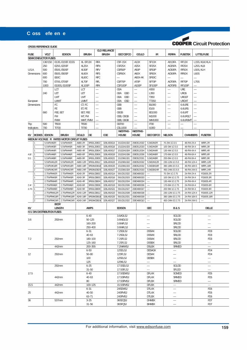
Circuit ProtectionCROSS REFERENCE GUIDE
OLD RELIANCE/FUSE VOLT EDISON BRUSH BRUSH GEC/CEFCO GOULD IR FERRA FUSETEK LITTELFUSESEMICONDUCTOR FUSES
130/150 E13S, E15SF, E15S XL-SF13X RFA CSF-15X A13X SF13X A013FA RF13X L15S, KLW, KLA250 E25S, E25SF XL25X RFN CSF25X A25X SF25X AO25FA RF25X L25S, KLB
U.S.A. 500 E50S, E50SF XL50F RFV CSF50P A50P SF50P AO50FA RF50X L50S, KLHDimensions 600 E60S, E60SF XL60X RFS CSF60X A60X SF60X AO60FA RF60X L60S
600 E60C XL60C RFC — A60X-4K SF60C — — —700 E70S, E70SF XL70F RFL CSF70P A70P SF70P AO70FA RF70P L70S1000 E100S, E100SF XL100P RFK CSF100P A100P SF100P AO70FB RF100P —
LCT LCT — GSA — A350 — URE —240 LET LET — GSA GSD — L350 — URGS —
LMT LMT — GSA GSD — T350 — URGGT —European LMMT LMMT — GSA GSD — TT350 — URGHT —Dimensions FC CT, FC — GSB — B1000 — 6.6URE —
FE ET, FE — GSB — E100 — 6.6URS —660 FEE, EET EET, FEE — GSGB — EE1000 — 6.6URT —
FM MT, FM — GSB, GSGB — M1000 — 6.6URGLT —FMM MMT, FMM — GSB, GSGB — MM1000 — 6.6URGMT —
Trip 500 TI500 TI500 — GS700 — I700 — — —Indicators 700 TI700 TI700 — CSL1000 — I1000 — — —
WESTING- WESTING-KV BODIES EDISON BRUSH GOULD GE CGE HOUSE HOUSE GEC/CEFCO NELSON CHAMBERS FUSETEK
MEDIUM VOLTAGE R RATED MOTOR CIRCUIT FUSES1 5.5VFNHA2R 5.5VFNHA2R A480-2R 9F60LJD802 328L493G14 151D241G02 208D512G02 5.5KDAX2R 70-2M-1C-5.5 48-FM-2X-4 MRP1.2R
1 5.5VFNHA3R 5.5VFNHA3R A480-3R 9F60LJD803 328L493G16 151D241G03 208D512G03 5.5KDAX3R 100-3M-1C-5.5 48-FM-3X-4 MRP1.3R
1 5.5VFNHA4R 5.5VFNHA4R A480-4R 9F60LJD804 328L493G17 151D241G04 208D512G04 5.5KDAX4R 130-4M-1C-5.5 48-FM-4X-4 MRP1.4R
4.8/ 1 5.5VFNHA6R 5.5VFNHA6R A480-6R 9F60LJD806 328L493G19 151D241G06 208D512G06 5.5KDAX6R 170-6M-1C-5.5 48-FM-6X-4 MRP1.6R
5.5 1 5.5VFNHA9R 5.5VFNHA9R A480-9R 9F60LJD809 328L493G21 151D961G01 208D522G01 5.5KDAX9R 200-9M-1C-5.5 48-FM-9X-4 MRP1.9R
1 5.5VFNHA12R 5.5VFNHA12R A480-12R 9F60LJD812 328L493G23 151D961G02 208D522G02 5.5KDAX12R 230-12M-1C-5.5 48-FM-12X-4 MRP1.12R
2 5.5VFNHK18R 5.5VFNHK18R A480-18R 9F60MJD818 328L493G25 151D961G03 208D522G02 5.5KDBX18R 390-18M-2C-5.5 48-FM-18X-5 MRP1.18R
2 5.5VFNHK24R 5.5VFNHK24R A480-24R 9F60MJD824 328L493G27 151D961G04 208D522G03 5.5KDBX24R 450-24M-2C-5.5 48-FM-24X-5 MRP1.24R
1 2.75VFRHA2R 2.75VFRHA2R A240-2R 9F60LCB802 328L492G14 591C812G02 208D480G02 — 70-2M-1C-2.75 24-FM-2X-4 FC6005.2R
1 2.75VFRHA3R 2.75VFRHA3R A240-3R 9F60LCB803 328L492G16 591C812G03 208D480G03 — 100-3M-1C-2.75 24-FM-3X-4 FC6005.3R
1 2.75VFRHA4R 2.75VFRHA4R A240-4R 9F60LCB804 328L492G17 591C812G04 208D480G04 — 130-4M-1C-2.75 24-FM-4X-4 FC6005.4R
2.4/ 1 2.75VFRHA6R 2.75VFRHA6R A240-6R 9F60LCB806 328L492G19 591C812G06 208D480G06 — 170-6M-1C-2.75 24-FM-6X-4 FC6005.6R
2.75 1 2.75VFRHA9R 2.75VFRHA9R A240-9R 9F60LCB809 328L492G21 591C812G07 208D480G07 — 200-9M-1C-2.75 24-FM-9X-4 FC6005.9R
1 2.75VFRHA12R 2.75VFRHA12R A240-12R 9F60LCB812 328L492G23 591C812G08 208D480G08 — 230-12M-1C-2.75 24-FM-12X-4 FC6005.12R
2 2.75VFRHK18R 2.75VFRHK18R A240-18R 9F60MCB818 328L492G25 591C812G01 208D480G09 — 390-18M-2C-2.75 24-FM-18X-5 FC6005.18R
2 2.75VFRHK24R 2.75VFRHK24R A240-24R 9F60MCB824 328L492G27 591C812G02 208D480G10 — 450-24M-2C-2.75 24-FM-24X-5 —
BODYKV LENGTH AMPS EDISON GEC B & S DELLEH.V. DIN DISTRIBUTION FUSES
6-40 3.6ADLSJ — SOLDD —3.6 292mm 50-125 3.6WDLSJ — SOLDD —
160-200 3.6WFLSJ — SRLDD —250-400 3.6WKLSJ — SRLDD —6-31 7.2SDLSJ DSSAX SOLDD FD340-63 7.2SDLSJ DSSAX SRLDD FD3
7.2 292mm 180-100 7.2SFLSJ DSSAX SRLDD FD3125-160 7.2SFLSJ DSSBX SRLDD —
442mm 200-355 7.2WKMSJ DSLBX SRMDD —6-50 12SDLSJ DESAGX — FD4
12 292mm 50-80 12SFLSJ DESAX — FD4100 12SDLSJ DESBX — —125 12SKLSJ — — —
292mm 6-25 17.5SDLSJ — SOLDD —31-50 17.5SFLSJ — SFLDD —
17.5 6-40 17.5SDMSJ DFLAX SOMDD FD5442mm 40-63 17.5SFMSJ DFLAX SRMDD FD5
80 17.5SFMSJ DFLBX SRMDD —15.5 442mm 100-125 15.5SFMSJ DFLBX — —
6-31 24SDMSJ DTLAX — FD625 442mm 40-50 24SFMSJ DTLAX — FD6
63-71 24SFMSJ DTLBX — FD636 537mm 3-25 36SDQSJ DHMBX — FD7
31-56 36SFQSJ BHMBX — FD7
C oss efe en e
159For additional information, visit www.edisonfuse.com
eo de 1005 0 11 5 nted n S
Customer Satisfaction - US and Canada
S .
S 8 00 . . 4 30 . . S .
S
636-391-3443 - 800-862-5178 - .
Online Resources . .
.
C3 – The Enhanced, Online Cooper Customer Center
.
A
. 3. 877-995-5955 -
Your Authorized Edison Distributor is:
Circuit Protection
ooper Industr ies Ltd600 Trav is , Ste . 5800Houston, TX 77002-1001P 713-209-8400www.cooper indust r ies .com
EdisonCooper Circuit Protectionwww.edisonfuse.com