Embed Size (px)
Citation preview

EDGE EVO is the next evolution in access control hardware solutions. A true IP solution that meets the demands of open architecture, IP-centric environments, EDGE EVO provides fully distributed intelligence and decision making right to the door, leveraging the IT infrastructure to the maximum extent possible. Leveraging Power-over-Ethernet (PoE), EDGE EVO reduces door installation costs by not requiring a separate local power supply under many circumstances.
The Standard Networked Controller is a fully integrated single-door controller offering discrete I/O and Wiegand/Clock-and-Data interfaces to readers. Additionally, connect native Hi-O devices (readers, locks, pushbuttons) and EDGE EVO Hi-O Modules to the Hi-O bus, providing secure communication around the door. Hi-O involves devices with built-in intelligence and a CANbus that links all the devices together. Password protect or encrypt Hi-O CANbus data traffic. Each Hi-O device (such as the REX switch, electric strike, card reader and door operator) is connected to the CANbus by a single, four-wire cable. Two of the wires supply power and the other two are used for data communication.
SpecificationsCONDITIONS VOLTAGE DC
(VDC)CURRENT (Amp)
OPERATING TEMPERTURE CABLE LENGTH UL REF
NUMBER
Inpu
t
DC Input (NSC)
+12VDC 0.18Amp
32° - 122°F(0° - 50° C)
Hi-O CAN Bus Total Length 100 ft (30 m) - 22 AWG ● 0.65mm ● 0.33mm2
Maximum between drops 30 ft (10 m) 22 AWG ● 0.65mm ● 0.33mm2
RJ45 328 ft (100 m) - Category 5 K
KE400CxNN
x =
K for Black
G for Grey
+24VDC 0.14Amp
PoE (+48VDC NOM) .085Amp
DC Input (MAX)
+12VDC 1.5Amp
+24VDC 1.5Amp
PoE +48VDC (NOM) 0.3Amp
Supervised inputs (AC, Batt, REX, Door Mon) (MAX) 0-+5VDC Reference 0.005Amp (sink)
Data 1/CLK , Data 0 / Data (MAX) 0-+5VDC Reference N/A
Oup
ut
GRN LED, RED LED, Beep, Hold (MAX) 0-+5VDC reference 0.005Amp (sink)
External Tamper (MAX) +5VDC (NOM) 0.02
CAN DC Output (MAX)
AUX 12 / 24VDC Input +10.8 to +24VDC 1.2Amp *
PoE Input + 24VDC (NOM) 0.4Amp *
Reader DC PWR Output (MAX)
AUX 12 VDC +9.8 to +12.25VDC 0.32Amp *
AUX 24VDC +9.8 to +12.25VDC 0.60Amp *
PoE Input +9.8 to +12.25VDC 0.58Amp *
Strike / AUX RelaysNC or NODC Output(MAX)
AUX 12VDC Input
Unregulated (Wet) Jumpers +10 to 12VDC 0.70Amp *
AUX 24VDC Input
Unregulated (Wet) Jumpers +23 to 24VDC 0.70Amp *
Regulated (Wet) Jumpers - 12VDC +10 to 12VDC 0.70Amp *
PoE Input
Unregulated (Wet) Jumpers +16.5 to 24VDC 0.36Amp *
Regulated (Wet) Jumpers - 12VDC +10 to 12VDC 0.58Amp *
AUX / PoE Input Jumpers Set to Dry +12 to 24VDC
External 2.00Amp **
NSC = Normal Standby Condition
* Combined output ratings, not to exceed 1.2 Amp
** Each Relay
EDGE EVO®
Standard Networked ControllerEH400-K
InstallatIon GuIde
82000-921, Rev C.0
October 2011
© 2009 - 2011 HID Global Corporation. All rights reserved.
15370 Barranca ParkwayIrvine, CA 92618-2215USA

Standard Networked Controller EH400-K
82000-921 C.0
INSTALLATION GUIDE2 ©2009 - 2011 HID Global Corporation. All rights reserved.
Before starting installation, determine which components will be used in the system and analyze the power requirements to avoid over-loading the EDGE EVO Hi-O Networked Controller & Reader (EH400-K).
The steps that follow illustrate sizing power requirements for the system.
Step 1 - Identify System ComponentsIdentify the components that will be used in the system. A typical installation may include the following components:
• Door Position Switch – Detects when the door is open or closed.
• Magnetic Lock – Holds the door locked.
• Request to Exit (REX) Switch – Unlocks the door when exiting the secured area.
• EDGE EVO Hi-O Standard Networked Controller (EH400-K) – Provides access control and manages all peripherals around the door.
• iCLASS Wiegand Reader – Provides entry into the secured area.
Step 2 - Create System LayoutUsing the components identified in “Step 1 - Identify System Components” on page 2, create the system layout. In this example, the EH400-K is connected to the remote server through an Ethernet connection and manages door peripherals over the Hi-O bus. Controlling downstream door peripherals, the EH400-K is a fully integrated single-door controller offering discrete I/O and Wiegand/Clock-and-Data interfaces to external readers. The EH400-K receives inputs from the Door Position Switch and REX Switch to drive the Magnetic Lock output.
Unprotected Area Protected Area
Physical AccessControl Server
(real-time functionsnot required )
Remote Area
Wiegand Ethernet Switch
Ethernet Data
Door Position Switch
Magnetic Lock
REX Switch
Wiegan
Door PSwi
Mag
cted
ne
Wiegand Reader
EH400-K
Figure 1 - System Layout Example
1 Power Analysis

82000-921 C.0
INSTALLATION GUIDE 3©2009 - 2011 HID Global Corporation. All rights reserved.
Standard Networked ControllerEH400-K
Step 3 - Analyze Power RequirementsA - Door Peripheral Operational CurrentsFor the door peripherals identified in “Step 1 - Identify System Components” on page 2, consult the vendor data sheets to determine the operational current draw. Typical operational current draw is provided below.Note: See individual peripheral data sheets for actual operational current draw.
Device Conditions Typical Operational CurrentDoor Position Switch Vin = 12VDC 15mA(For example, Securitron MSS) Vin = 24VDC 15mAMag Lock Vin = 12VDC 300mA(For example, Securitron M32) Vin = 24VDC 150mAREX Switch Vin = 12VDC 28mA(For example, Securitron EEB) Vin = 24VDC 38mAiCLASS Wiegand Reader Vin = 12VDC 150mA
B - Match I/O Requirements to the Hi-O Interface DeviceFor the door peripherals identified in “Step 1 - Identify System Components” on page 2, the system requires direct connection to I/O interface and Wiegand/Clock-and-Data ports of the EH400-K. A separate Hi-O Interface Device is not required.
C - Compute and Compare Overall Current DrawCalculate the total current draw for all door peripherals and the attached Wiegand readers with the following equation, adding terms as required.
I total = I dps + I mag + I rex + … + I iCLASS reader
The following calculations provide load current computations.
Itotal @ 12VDC = 15mA + 300mA + 28mA + 150mA = 493mAItotal @ 24VDC = 15mA + 150mA + 38mA + 150mA = 353mA
Compare the required current draw (I total) to the output current capacity of the EH400-K (see Specification table, pg 1) to select the Eh400-K power scheme. The CAN DC Pwr Output represents the entire power output capacity of the EH400-K.
Device Port Conditions Vout I outStandard Networked Controller
(EH400-K)CAN DC PWR Output (MAX)
AUX 12-24VDC Input +10.8 to +24VDC 1.2APoE input +24VDC (NOM) 400mA
In this example, the EH400-K provides sufficient power when operated with a PoE injector, or +12/24VDC auxiliary power supplies. Directly connect the door peripherals identified in “Step 1 - Identify System Components” on page 2 to the EH400-K I/O ports per the “Specifications” on page 1 for the selected input power scheme. Ensure all door peripherals connected to the Strike/AUX relays and the Reader DC Pwr Output or both do not exceed 1.2Amps (AUX Input) or 0.4Amps (PoE Input), combined. Alternatively, the door peripherals may be connected to the Strike/AUX relays configured for Dry contact up to 2Amps per relay.

Standard Networked Controller EH400-K
82000-921 C.0
INSTALLATION GUIDE4 ©2009 - 2011 HID Global Corporation. All rights reserved.
The door peripherals identified in “Step 1 - Identify System Components” on page 2 should be directly connected to the I/O ports of the EH400-K. The I/O ports may be configured to provide the following output current capacity.
Device Ports Conditions I out
EDGE EVO Hi-O Standard Network Controller (EH400-K)
Strike / AuxNC or NODC Output
+12VDC unregulated (@ +12VDC EDM-M input) 600 mA*
+24VDC unregulated (@ +24VDC EDM-M input) 600 mA*
+12VDC regulated (@ +24VDC EDM-M input) 3 mA*
Dry Jumpers +12VDC to +24VDC External 2.00 Amp**
Reader Power +9.8VDC to +12.25 VDC 320-600mA*
* = Combined output ratings, not to exceed 1.2 Amp
** = Each relay
Ensure door peripherals connected to the Strike/AUX relays (regulated/unregulated) do not exceed 1.2 Amps combined. Alternatively, the door peripherals may be connected to the Strike/AUX relays configured for Dry contact up to 2 Amps.
Ensure Wiegand / Clock-and-Data readers attached to the reader port do not exceed:
320mA @ +9.8VDC
or
600mA @ +12.25VDC
82000-921 C.0
INSTALLATION GUIDE 5©2009 - 2011 HID Global Corporation. All rights reserved.
Standard Networked ControllerEH400-K
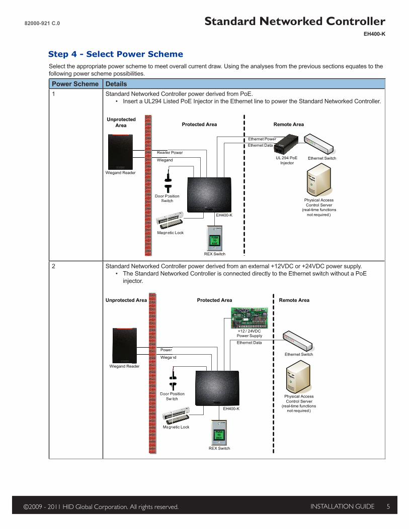
Step 4 - Select Power SchemeSelect the appropriate power scheme to meet overall current draw. Using the analyses from the previous sections equates to the following power scheme possibilities.
Power Scheme Details1 Standard Networked Controller power derived from PoE.
• Insert a UL294 Listed PoE Injector in the Ethernet line to power the Standard Networked Controller.
Protected Area Remote Area
Wiegand
Ethernet Data
Door Position Switch
Magnetic Lock
REX Switch
Wiegand Reader
EH400-K
Unprotected Area
Reader Power
Ethernet Power
Wiega
Door PoSwi
Magne
ader
cted
Reade
Physical AccessControl Server
(real-time functionsnot required )
Ethernet SwitchUL 294 PoE Injector
er
2 Standard Networked Controller power derived from an external +12VDC or +24VDC power supply.• The Standard Networked Controller is connected directly to the Ethernet switch without a PoE
injector.
Protected Area
Physical AccessControl Server
(real-time functionsnot required )
Remote Area
WiegandEthernet Switch
Ethernet Data
Door Position Switch
Magnetic Lock
REX Switch
Wiegand Reader
EH400-K
Unprotected Area
+ / 24VDC 12 Power Supply
Power
Wiegan
Door PSwi
Magn
ader
d Area
Power

Standard Networked Controller EH400-K
82000-921 C.0
INSTALLATION GUIDE6 ©2009 - 2011 HID Global Corporation. All rights reserved.
Hi-O Group Select Jumper Short = Group 1, Open = Group 2Outside Door Inside Door( )
1 P3
12
1 P1
4
CAN V+ GNDCAN_HCAN_L
RDR PWRGNDData0 / DataData1 / CLK*GRN LEDRED LED
Hold*Beep
GRP SEL
+-
10
P3
14
P1
1
+-
Hi-O Group Select Jumper Short = Group 1, Open = Group 2
Outside Door Inside Door( )
+-
*
NC
NO
COM
NC
NO
COM
Relay Jumpers
6 P1
0 1
AUX+DC
AUXGND
+-
Reader Tamper +
Doo
r Stri
keAU
X
AC FAILINPUT SENSE
REX
Door Mon
* = Internal Optical Tamper Disable
BATT FAILINPUT SENSE
Note: Connect the Door Monitor to avoid a Force Door Alarm.
P9
P5
P8
P6
P4
P7
Ethernet / PoEAuto-Detected
Activity LED
Link LED
Hi-O
CA
Nbu
s
Reader Tamper -
2 Mounting
Junction box not included.
Wiring3
OptionalSupervised Inputs
1-6KN/O1-6K
N/C1-6K
1-6KN/O
ATTENTIONObserve precautions for handling
ELECTROSTATIC SENSITIVE DEVICES
82000-921 C.0
INSTALLATION GUIDE 7©2009 - 2011 HID Global Corporation. All rights reserved.
Standard Networked ControllerEH400-K
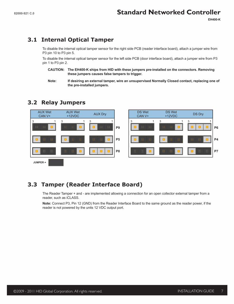
3.1 Internal Optical TamperTo disable the internal optical tamper sensor for the right side PCB (reader interface board), attach a jumper wire from P3 pin 10 to P3 pin 5.To disable the internal optical tamper sensor for the left side PCB (door interface board), attach a jumper wire from P3 pin 1 to P3 pin 2.
CAUTION: The EH400-K ships from HID with these jumpers pre-installed on the connectors. Removing these jumpers causes false tampers to trigger.
Note: If desiring an external tamper, wire an unsupervised Normally Closed contact, replacing one of the pre-installed jumpers.
3.2 Relay JumpersAUX WetCAN V+
AUX Wet+12VDC AUX Dry DS Wet
CAN V+DS Wet+12VDC DS Dry
3 1
P9
P5
P8
3 1 3 1 3 1
P6
P4
P7
3 1 3 1
JUMPER =
3.3 Tamper (Reader Interface Board)The Reader Tamper + and - are implemented allowing a connection for an open collector external tamper from a reader, such as iCLASS.Note: Connect P3, Pin 12 (GND) from the Reader Interface Board to the same ground as the reader power, if the reader is not powered by the units 12 VDC output port.
Standard Networked Controller EH400-K
82000-921 C.0
INSTALLATION GUIDE8 ©2009 - 2011 HID Global Corporation. All rights reserved.
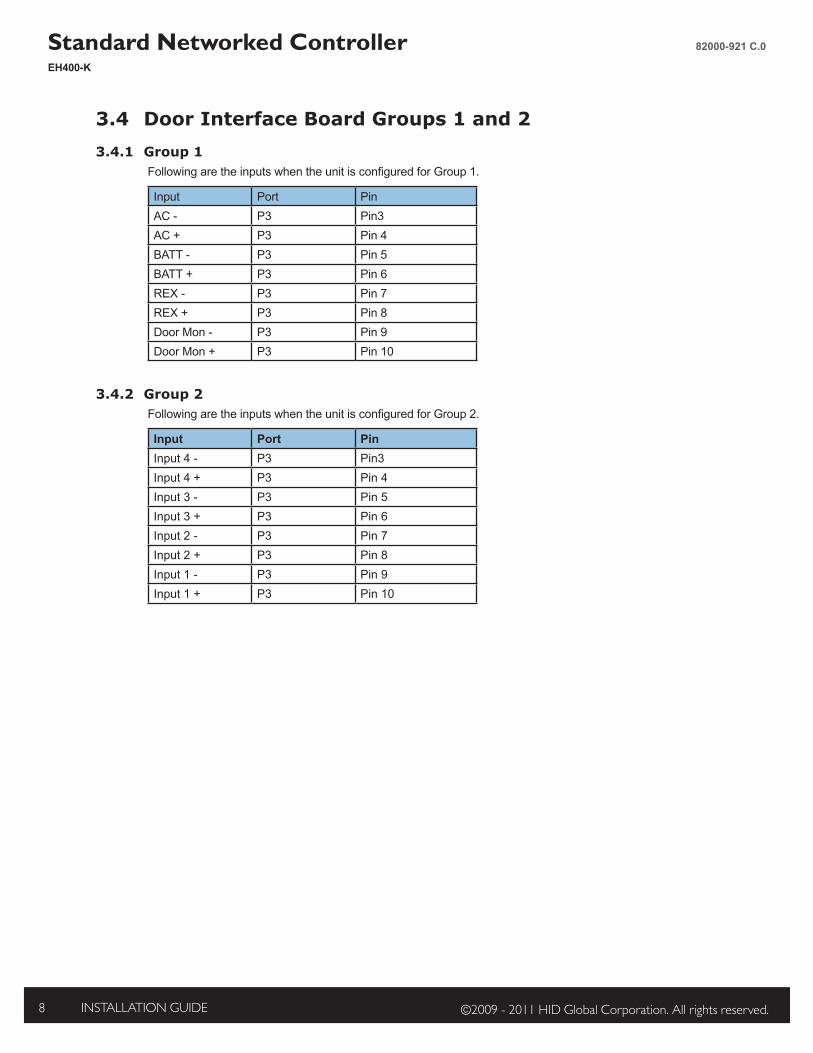
3.4 Door Interface Board Groups 1 and 23.4.1 Group 1
Following are the inputs when the unit is configured for Group 1.
Input Port PinAC - P3 Pin3AC + P3 Pin 4BATT - P3 Pin 5BATT + P3 Pin 6REX - P3 Pin 7REX + P3 Pin 8Door Mon - P3 Pin 9Door Mon + P3 Pin 10
3.4.2 Group 2Following are the inputs when the unit is configured for Group 2.
Input Port PinInput 4 - P3 Pin3Input 4 + P3 Pin 4Input 3 - P3 Pin 5Input 3 + P3 Pin 6Input 2 - P3 Pin 7Input 2 + P3 Pin 8Input 1 - P3 Pin 9Input 1 + P3 Pin 10

82000-921 C.0
INSTALLATION GUIDE 9©2009 - 2011 HID Global Corporation. All rights reserved.
Standard Networked ControllerEH400-K
Contact EDGE EVO through one of the following methods.
5.1 Direct ConnectIf EDGE EVO will be connected to a network using static IP addressing or if the Discovery GUI is not installed on the PC, use this method.
Note: The computer must be running Windows 2000 or XP and be configured for DHCP.
1. Disconnect the computer from the network and directly connect EDGE EVO to the computer with an Ethernet cable.2. Click Start > Run. Enter ipconfig /renew ↵3. Access a web browser and enter 169.254.242.121 into the Address field ↵
5.2 OPIN Discovery/Update ApplicationUse the OPIN Discovery / Update Application on a computer to locate, connect and update EDGE EVO.
System Requirements: Java 6.0 or later. Go to www.java.com to download.Operating Systems: Windows XP and Fedora 8.
Find the OPIN Discovery / Update Application at www.ShareMethods.com > OPIN > Firmware > 2.3.x. Save the files to your local harddrive.
Install to Backplate4
Contact5

Standard Networked Controller EH400-K
82000-921 C.0
INSTALLATION GUIDE10 ©2009 - 2011 HID Global Corporation. All rights reserved.
The EDGE EVO must be connected to the network, and power applied, before the device is discovered.
1. With a computer connected to the same network as EDGE EVO, double-click opin-update.jar. The OPIN Discovery / Update Application opens and the Controller Table populates.Note: If the Controller Table does not populate, go to Edit > Broadcast Address. The default broadcast address is 255.255.255.255. Some network switches may block this transmission. If this is the case, change the subnet to match the network, for example 10.7.255.255. Click Save.
2. Select the desired device from the list.3. From Path to Update Package frame, browse to the firmware location on the computer.4. Click Install. Firmware is installed.
EH400K - Provides additional functionality to not only Install firmware, but to Changeover, and Rollback firmware updates. Once firmware is installed, click Changeover to switch to the updated firmware. Click Rollback to switch back to the previous firmware version.
5. View the Status Log for each status while performing Discovery and Update functions.
The web browser will prompt for login information. From the Login screen enter admin, leaving the Password field empty. Follow the instructions on the web browser screen to configure EDGE EVO.
Test the system once per year using the web Graphical User Interface to ensure all wiring and configuration is correct.
For additional installation information, such as PIR and other active Request-to-Exit (REX) devices, as well as connecting fire relays, see http://www.hidglobal.com/edgesupport.
Configure6
Power & Testing7

82000-921 C.0
INSTALLATION GUIDE 11©2009 - 2011 HID Global Corporation. All rights reserved.
Standard Networked ControllerEH400-K
Hi-O Interface ModulesHi-O interface modules are used to expand functionality of the EDGE EVO Networked Controller. Hi-O interface modules connect the native Hi-O bus with additional components around and behind doors and other access points.For Hi-O interface module wiring, see their prospective Installation Guides.Go to www.hidglobal.com > Support > Document Library. Search the document type as a Installation Guide.
Model Description Part NumberEDM-M EDGE EVO Door Module 82342EIM-M EDGE EVO Input Module 82340EWM-M EDGE EVO Reader Module 82360EDWM-M EDGE EVO Door & Reader Module 82363AMELM EDGE EVO Lock Module 82301EVM EDGE EVO Voltage Module 82365
GlossaryAcronym Description Acronym DescriptionAC Fail AC Power Failure Input GND GroundAUX Auxillary Output GRN LED Green LED OutputBATT Fail Battery Failure Input GRP SEL Group SelectCAN_H Hi-O CANbus High NC Normally ClosedCAN_L Hi-O CANbus Low NO Normally OpenCLK Clock PIR Passive Infared deviceCOM Common PoE Power over EthernetData0 Wiegand Data 0 Input RED LED Red LED OutputData1 Wiegand Data 1 Input REX Request-to-Exit InputDoor Mon Door Monitor Input RLY RelayDS Door Strike

RegulatoryULConnect only to a Listed Access Control / Burglary power-limited power supply, or Listed Access Control / Burglary PoE (Power-over-Ethernet) adapter. All National and local Electrical codes apply. Install in accordance with NFPA70 (NEC), Local Codes, and authorities having jurisdiction. Host-based security, Ethernet / Host Communication, has not been evaluated by UL. Ethernet port has been evaluated for supplemental use only.Indoor use only. The EDGE EVO family has been evaluated for standalone Access Control.Mount onto UL Listed Single-Gang electrical box.Standard Networked Controller and EDGE EVO Modules are UL Listed for installation within the protected area.All panic and alarm hardware and equipment shall be UL Listed.All cabling and wire shall be UL Listed or Recognized and suitable for the application.All splices and connections shall be mechanically secure and bonded electrically.EDGE EVO was evaluated for use with all Listed HID Global Wiegand models: iCLASS, Indala Prox, HID Prox, bioCLASS, SmartID, SmartTRANS, and Mag Stripe series (with and without keypad), up to 128-bit formats. EDGE EVO was evaluated for use with all HID Global Hi-O iCLASS readers.Controller / Reader & Module or Networked Controller are UL Listed for installation in the unprotected area, as well as within the protected area.
FCC / CANADA RADIO CERTIFICATIONCAUTION: Any changes or modifications to this device not explicitly approved by manufacturer could void your authority to operate this equipment.This device complies with part 15 of the FCC Rules. Operation is subject to the following two conditions: (1) This device may not cause harmful interference, and (2) this device must accept any interference received, including interference that may cause undesired operation.This device complies with Industry Canada license-exempt RSS standard(s). Operation is subject to the following two conditions: (1) This device may not cause interference, and (2) This device must accept any interference, including interference that may cause undesired operation of the device.
CE MARKINGHID Global hereby declares that these proximity readers are in compliance with the essential requirements and other relevant provisions of Directive 1999/5/EC.Por el presente, HID Global declara que estos lectores de proximidad cumplen con los requisitos esenciales y otras disposiciones relevantes de la Directiva 1999/5/EC.HID Global déclare par la présente que ces lecteurs à proximité sont conformes aux exigences essentielles et aux autres stipulations pertinentes de la Directive 1999/5/CE.A HID Global, por meio deste, declara que estes leitores de proximidade estão em conformidade com as exigências essenciais e outras condições da diretiva 1999/5/EC.HID Global bestätigt hiermit, dass die Leser die wesentlichen Anforderungen und anderen relevanten Bestimmungen der Richtlinie 1999/5/EG erfüllen.HID Global dichiara che i lettori di prossimità sono conformi ai requisiti essenziali e ad altre misure rilevanti come previsto dalla Direttiva europea 1999/5/EC.
Download copies of the R&TTE Declaration of Conformity (DoC) at http://certifications.hidglobal.com.
JAPAN MICこの装置は認証済みです。
TAIWAN NCC經型式認證合格之低功率射頻電機,非經許可,公司、商號或使用者均不得擅自變更頻率、加大功率或變更原設計之特性及功能。低功率射頻電機之使用不得
影響飛航安全及干擾合法通信;經發現有干擾現象時,應立即停用,並改善至無干擾時方得繼續使用。前項合法通信,指依電信法規定作業之無線電通信。低功
率射頻電機須忍受合法通信或工業、科學及醫療用電波輻射性電機設備之干擾。According to «Administrative Regulations on Low Power Radio Waves Radiated Devices» without permission granted by the NCC, any company, enterprise, or user is not allowed to change frequency, enhance transmitting power or alter original characteristic as well as performance to an approved low power radio-frequency devices. The low power radio-frequency devices shall not influence aircraft security and interfere legal communications; If found, the user shall cease operating immediately until no interference is achieved. The said legal communications means radio communications is operated in compliance with the Telecommunications Act.The low power radio-frequency devices must be susceptible with the interference from legal communications or ISM radio wave radiated devices.
hidglobal.comACCESS experience.
North America
15370 Barranca ParkwayIrvine, CA 92618USAPhone: 800 237 7769Fax: 949 732 2120
Asia Pacific
19/F 625 King’s RoadNorthPoint, Island EastHong KongPhone: 852 3160 9800Fax: 852 3160 4809
Europe, Middle East & Africa
Phoenix RoadHaverhill, Su�olk CB9 7AEEnglandPhone: +44 1440 714 850Fax: +44 1440 714 840
HID Global
support.hidglobal.com
© 2009 - 2011 HID Global Corporation. All rights reserved1 82000-921 Rev C.0
Patent Pending
Check reader label for current regulatory approvals.
HID GLOBAL, HID, the HID logo, EDGE EVO and Hi-O are the trademarks or registered trademarks of HID Global Corporation, or its licensors, in the U.S. and other countries.