Embed Size (px)
Citation preview
1/38
Dokument: [email protected]
ECU MASTER scheme & configuration
ideas make future
© IMFsoft, ltd.
Ideas make future
3.8.2017
ECU MASTER
CDI - TCI
scheme & configuration
Rev 8.43
2/38
Dokument: [email protected]
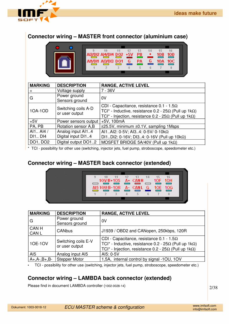
Connector wiring – MASTER front connector (aluminium case)
MARKING DESCRIPTION RANGE, ACTIVE LEVEL+ Voltage supply 7 - 36V
GPower ground Sensors ground
0V
1OA-1ODSwitching coils A-Dor user output
CDI - Capacitance, resistance 0.1 - 1.5Ω
TCI* - Inductive, resistance 0.2 - 25Ω (Pull up 1kΩ)
TCI* - Injection, resistance 0.2 - 25Ω (Pull up 1kΩ)+5V Power sensors output +5V, 100mAPA, PB Rotation sensor A,B ±25.5V, minimum ±0.1V, sampling 1MspsAI1.. AI4 / DI1.. DI4
Analog input AI1..4Digital input DI1..4
AI1..AI2: 0-5V; AI3..4: 0-5V/ 0-10kΩ
DI1..DI2: 0-16V; DI3..4: 0-16V (Pull up 10kΩ)
DO1, DO2 Digital output DO1..2 MOSFET BRIDGE 5A/40V (Pull up 1kΩ)
* TCI - possibility for other use (switching, injector jets, fuel pump, stroboscope, speedometer etc.)
Connector wiring – MASTER back connector (extended)
MARKING DESCRIPTION RANGE, ACTIVE LEVEL
GPower ground Sensors ground
0V
CAN HCAN L
CANbus J1939 / OBD2 and CANopen, 250kbps, 120R
1OE-1OVSwitching coils E-Vor user output
CDI - Capacitance, resistance 0.1 - 1.5Ω
TCI* - Inductive, resistance 0.2 - 25Ω (Pull up 1kΩ)
TCI* - Injection, resistance 0.2 - 25Ω (Pull up 1kΩ)AI5 Analog input AI5 AI5: 0-5VA+,A-,B+,B- Stepper Motor 1,5A, internal control by signal -1OU, 1OV
• TCI - possibility for other use (switching, injector jets, fuel pump, stroboscope, speedometer etc.)
Connector wiring – LAMBDA back connector (extended)
Please find in document LAMBDA controller (1002-0028-14)
ECU MASTER scheme & configuration
ideas make future

3/38
Dokument: [email protected]
Connector wiring – MASTER MINI (orange plastic case)
MARKING DESCRIPTION RANGE, ACTIVE LEVEL+ Voltage supply 3.5 - 25V
GPower ground Sensors ground
0V
1OA-1OCSwitching coils A-Cor user output
TCI* - Inductive, resistance 0.2 - 25Ω (Pull up 1kΩ)
TCI* - Injection, resistance 0.2 - 25Ω (Pull up 1kΩ)
+5V Power sensors output +5V, 100mAPA Rotation sensor A ±25.5V, minimum ±0.1V, sampling 1MspsAI1, AI2 / DI1, DI2, DI3
Analog input AI1,2Digital input DI1,2,3
AI1: 0-5V/ 0-10kΩ; AI2: 0-5V
DI2: 0-16V; DI1,DI3: 0-16V (Pull up 10kΩ)DO1 Digital output DO1 MOSFET 1A/100V (Pull up 1kΩ) - not in Bridge
* TCI - possibility for other use (switching, injector jets, fuel pump, stroboscope, speedometer etc.)
MASTER MINI does not contain these signals: AI3, AI4, D4, PB, 1OD, but all software functions are present. Please choose in MASTER Control Application in menu “i” → HARDWARE VARIANT → V7.x
Connector wiring – MASTER LITE (aluminium case)
MARKING DESCRIPTION RANGE, ACTIVE LEVEL+ Voltage supply 3.5 - 21V
GPower ground Sensors ground
0V
1OA-1OBSwitching coils A-Bor user output
TCI* - Inductive, resistance 0.2 - 25Ω (Pull up 1kΩ)
TCI* - Injection, resistance 0.2 - 25Ω (Pull up 1kΩ)PA Rotation sensor A ±25.5V, minimum ±0.1V, sampling 1MspsAI1 / DI1 Analog input AI1
Digital input DI1AI1: 0-5V/ 0-10kΩ;
DI1: 0-16V (Pull up 10kΩ)
* TCI - possibility for other use (switching, injector jets, fuel pump, stroboscope, speedometer etc.)
MASTER LITE does not contain these signals: AI2,AI3,AI4,DI2,DI3,DI4,PB,1OC,1OD,DO1,DO2, but all software functions are present. Please choose in MASTER Control Application in menu “i”→ HARDWARE VARIANT → V7.x
ECU MASTER scheme & configuration
ideas make future

4/38
Dokument: [email protected]
Outputs plugging – CDI and TCI
The table bellow describes the arrangement outputs for each type of MASTER unit. Outputs CDI and TCI are arranged in the order and number of signs MASTER, eg. MASTER 2xCDI 2xTCI contains first outputs CDI for 1OA,1OB and next TCI for 1OC, 1OD.
MASTER type 1OA 1OB 1OC 1OD 1OE 1OF 1OG 1OH 1OR 1OS
2xTCI (LITE) TCI TCI
3xTCI (MINI) TCI TCI TCI
1xCDI 3xTCI CDI TCI TCI TCI
2xCDI 2xTCI CDI CDI TCI TCI
3xCDI 1xTCI CDI CDI CDI TCI
4xTCI TCI TCI TCI TCI
4xCDI CDI CDI CDI CDI
2xCDI 8xTCI CDI CDI TCI TCI TCI TCI TCI TCI TCI TCI
3xCDI 7xTCI CDI CDI CDI TCI TCI TCI TCI TCI TCI TCI
4xCDI 6xTCI CDI CDI CDI CDI TCI TCI TCI TCI TCI TCI
5xCDI 5xTCI CDI CDI CDI CDI CDI TCI TCI TCI TCI TCI
6xCDI 4xTCI CDI CDI CDI CDI CDI CDI TCI TCI TCI TCI
8xCDI 2xTCI CDI CDI CDI CDI CDI CDI CDI CDI TCI TCI
10xTCI TCI TCI TCI TCI TCI TCI TCI TCI TCI TCI
10xCDI CDI CDI CDI CDI CDI CDI CDI CDI CDI CDI
* TCI - possibility for other use (switching, injector jets, fuel pump, stroboscope, speedometer etc.)
ECU MASTER scheme & configuration
ideas make future

5/38
Dokument: [email protected]
Installation
Electronic spark ignition unit ECU MASTER is powered by safe voltage upto 36V, but there is present a voltage of thousands of volts on ignitioncoils!!! Therefore, it is necessary to pay maximum attention whenmanipulating. Any changes to the electrical installation of ignition cannotbe carried on unless the power is off!!!
Power supply and all ignition inputs are protected against overvoltage and reverse polarity.Neither overvoltage status nor reverse polarity can last permanently, as it can overload thesecurity elements and cause partial or complete damage to the functionality of the ignition.
Ignition outputs are not protected against short circuit and thereforeoutputs from 1OA up to 1OV, DO1 or DO2 must not be connected to thepower terminal (+). Connection to impendence is also forbidden as it wouldexcess the amount of allowed current and result in overload and followingdestruction of certain switching elements in the ignition.
Spark plug together with cylinder head and engine block must be connected to negative orpositive pole of the power. This is necessary to flow of current from secondary winding ofignition coils.
Aluminium housing if ignition is due to own shielding connected to negative pole. Thereforeno other conductor apart from negative pole can be connected to the housing.
Ignition must never be installed at the places with direct exposure to water, chemicals,extreme temperatures and vibrations. The effect of any of these may cause irreversibledamage or destruction of ignition functionality.
The correct and reliable function of installed equipment is based on itscorrect power supply. Power wires (+, G) must have a diameter of 1.5mm2, which is ideal for CDI variant. Variant TCI must follow thiscondition only in case of ground wire (G). Power supply must always
be done through fuse 10A, which protects ignition in case of reverse polarity, overvoltage orother disorders.
Sparks must be provided with shielding caps and ideal use cable with a carbon core. Thesignal conductor from the rotation sensor cannot be led in parallel way with excitation coil wire(1OA to 1OV), high-voltage conductors or conductors of the alternator excitation. If it is notpossible to carry out the wiring in this way it is recommended to lead signal conductor sensors(PA, PB) in twisted (twisted in pair) or shielded conductors in order to eliminate any possibleinterference of electric-installation.
Connectors crimping
Connector crimping requires a similar procedure as with FASTON connectors, although there is a rubber sealing grommet used here in addition. Regarding tool, it can be done with standard crimping pliers FASTON 1.5mm – 2.5mm. For blocking of unused terminal connectors TYCO it is appropriate to use supplied rubber plugs to comply with IP65 degree of protection.
ECU MASTER scheme & configuration
ideas make future
6/38
Dokument: [email protected]
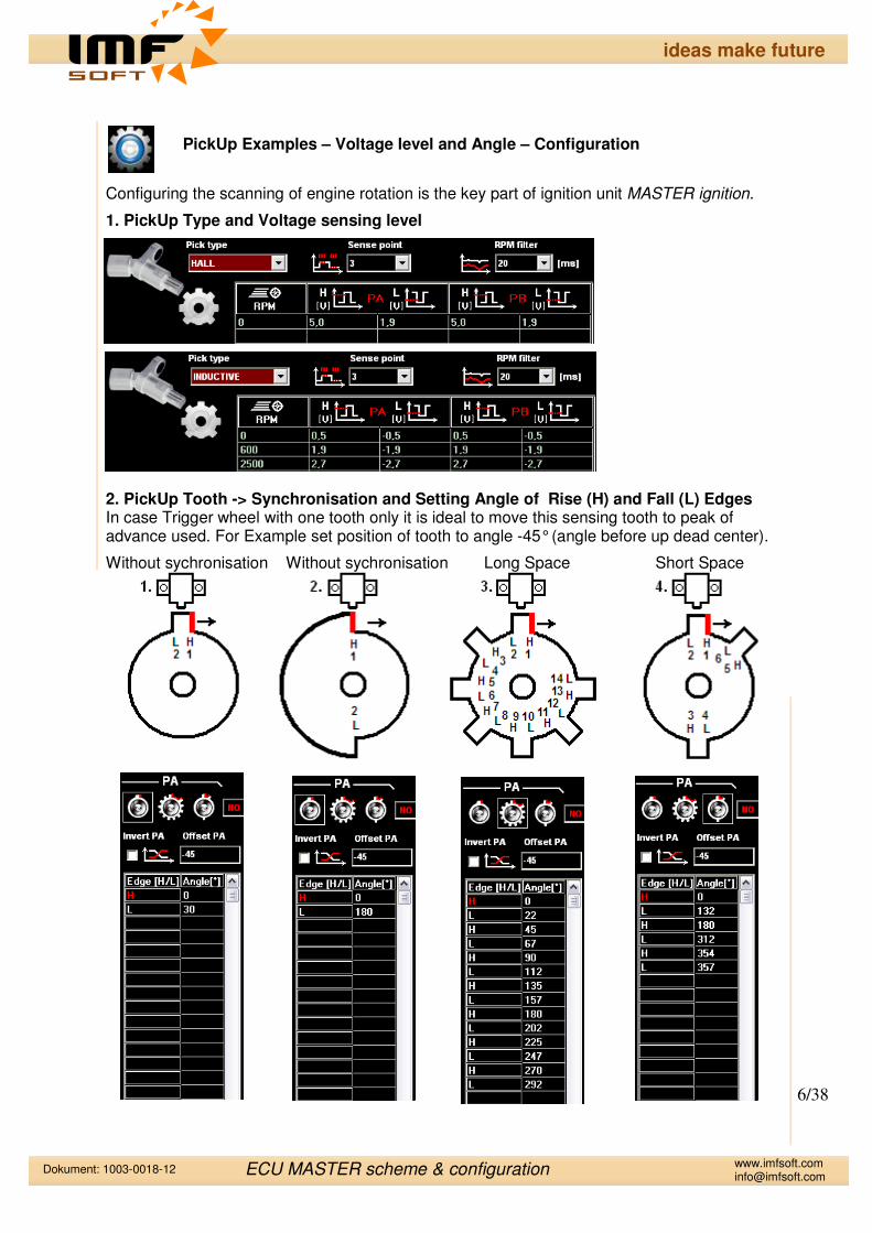
PickUp Examples – Voltage level and Angle – Configuration
Configuring the scanning of engine rotation is the key part of ignition unit MASTER ignition.
1. PickUp Type and Voltage sensing level
2. PickUp Tooth -> Synchronisation and Setting Angle of Rise (H) and Fall (L) EdgesIn case Trigger wheel with one tooth only it is ideal to move this sensing tooth to peak of advance used. For Example set position of tooth to angle -45° (angle before up dead center).
Without sychronisation Without sychronisation Long Space Short Space
ECU MASTER scheme & configuration
ideas make future

7/38
Dokument: [email protected]
Oscilloscopic record
Oscilloscopic record is used in order to graphically visualise measured and calculated data. Please use oscilloscope record before you connect output coils. This helps to quickly evaluate the proper and accurate function of ignition unit MASTER.
An example to be given; curve angle of engine angular rotation must be regularly and horizontally increased from 0 to 360°. If there is any change of steepness in the curve or the angle is shorten, the problem is to be found either in wrong angle value set up, number of teeth, the type of synchronisation or unsuitable voltage for sensing.
Visualised data
−Rotation pick up sensor voltage, PA, PB [V]
−Tooth index of pick up Trigger wheel, Tooth index A-B [-]−Engine angular rotation, Angle A-B [°]−Engine speed, Speed A-B [%]−Outputs switching 1OA-1OV [-]
ECU MASTER scheme & configuration
ideas make future

8/38
Dokument: [email protected]
Connecting of Pick up sensors PA, PB
Analog inputs AI1, AI2, AI3, AI4
It is possible to connect sensors whose output is either voltage or resistance to analoginputs AI1, AI2, AI3 and AI4, where AI1, AI2 works with voltage 0-5V and AI3, AI4 works with
voltage 0-5V or resistance 0-10kΩ. Signal from analog sensors should be lead by Twisted orshielded cable, which helps significantly to eliminate interference.
Digital inputs DI1, DI2, DI3, DI4
Change of input status DI3 and DI4 is easily done by input earthing or Bat. supply DI1, DI2.
Digital outputs DO1, DO2
Digital outputs can be used for load switching to zero or to supply with maximum currentload 5A. Therefore it is possible to connect e.g. relay coil, fuel pumpe, servo control, indicatorof shift revolutions, stroboscope etc.
ECU MASTER scheme & configuration
ideas make future

9/38
Dokument: [email protected]
ECU MASTER LITE
1. Example connecting of one HALL pickup sensor and one TCI coil
1x HALL pickup sensor connected to PA input 1x TCI coil connected to 1OA output
MASTER outputs configuration
- Out setting to angle 0°, where XA is reserved for 1OA - TCI excitation time 2ms (XTIME) - Used output 1OA - Pick up tooth is setuped to peak of advance or use more teeth for a precision sensing
Example of Configuration FILE [*.ig]:
Example[01]_LITE_1xHALL_1xTCI
ECU MASTER scheme & configuration
ideas make future

10/38
Dokument: [email protected]
ECU MASTER LITE
2. Example connecting of one INDUCTIVE pickup sensor and one TCI coil
1x INDUCTIVE pickup sensor connected to PA input 1x TCI coil connected to 1OA output
MASTER outputs configuration
- Out setting to angle 0°, where XA is reserved for 1OA - TCI excitation time 2ms (XTIME) - Used output 1OA - Pick up tooth is setuped to peak of advance or use more teeth for a precision sensing
Example of Configuration FILE [*.ig]:
Example[02]_LITE_1xINDUCTIVE_1xTCI
ECU MASTER scheme & configuration
ideas make future

11/38
Dokument: [email protected]
ECU MASTER LITE
3. Example connecting of one INDUCTIVE pickup sensor, one TCI coil and Advance Switch
1x INDUCTIVE pickup sensor connected to PA input 1x TCI coil connected to 1OA output 1x SWITCH conected to AI1/DI1 (select advance curve 1 or curve 2)
MASTER outputs configuration
- Out setting to angle 0°, where XA is reserved for 1OA - TCI excitation time 2ms (XTIME) - Used output 1OA - Pick up tooth is setuped to peak of advance or use more teeth for a precision sensing
Example of Configuration FILE [*.ig]:
Example[03]_LITE_1xINDUCTIVE_1xTCI_1xSWITCH
ECU MASTER scheme & configuration
ideas make future

12/38
Dokument: [email protected]
ECU MASTER LITE
4. Example connecting of one INDUCTIVE pickup sensor, one TCI coil and Temperature measurement
1x INDUCTIVE pickup sensor connected to PA input 1x TCI coil connected to 1OA output 1x TEMPERATURE sensor conected to AI1/DI1 (select advance curve 1 or curve 2)
MASTER outputs configuration
- Out setting to angle 0°, where XA is reserved for 1OA - TCI excitation time 2ms (XTIME) - Used output 1OA - Pick up tooth is setuped to peak of advance or use more teeth for a precision sensing
Example of Configuration FILE [*.ig]:
Example[04]_LITE_1xINDUCTIVE_1xTCI_1xTEMP
ECU MASTER scheme & configuration
ideas make future

13/38
Dokument: [email protected]
ECU MASTER LITE
5. Example connecting of one INDUCTIVE pickup sensor and one TCI coil (Battery PLUS pole connected to case!!)
1x INDUCTIVE pickup sensor connected to PA input 1x TCI coil connected to 1OA output
MASTER outputs configuration
- Out setting to angle 0°, where XA is reserved for 1OA - TCI excitation time 2ms (XTIME) - Used output 1OA - Pick up tooth is setuped to peak of advance or use more teeth for a precision sensing
Example of Configuration FILE [*.ig]:
Example[05]_LITE_1xINDUCTIVE_1xTCI
ECU MASTER scheme & configuration
ideas make future

14/38
Dokument: [email protected]
ECU MASTER LITE
6. Example connecting of one INDUCTIVE pickup sensor and two TCI coils
1x INDUCTIVE pickup sensor connected to PA input 2x TCI coils connected to 1OA,1OB outputs
MASTER outputs configuration
- Out setting to angle 0°, where XA is reserved for 1OA and XB is reserved for 1OB - TCI excitation time 2ms (XTIME) - Used outputs 1OA, 1OB - Pick up tooth with length 180° is setuped to peak of advance or use more teeth for a precision sensing
Example of Configuration FILE [*.ig]:
Example[06]_LITE_1xINDUCTIVE_2xTCI
ECU MASTER scheme & configuration
ideas make future

15/38
Dokument: [email protected]
ECU MASTER LITE
8. Example connecting of one INDUCTIVE pickup sensor , one TCI coils and distributor
1x INDUCTIVE pickup sensor connected to PA input 1x TCI coils connected to 1OA outputs 1x Distributor connected to TCI coils
MASTER outputs configuration
- Out setting to angle 0° and 180°, where XA is reserved for 1OA 1OB must be setuped same as 1OA - TCI excitation time 2ms (XTIME) - Used outputs 1OA - Pick up tooth with length 30° is setuped to peak of advance or use more teeth for a precision sensing
Example of Configuration FILE [*.ig]:
Example[08]_4xTCI_1xINDUCTIVE_1xTCI_1xDISTRIBUTOR
ECU MASTER scheme & configuration
ideas make future

16/38
Dokument: [email protected]
ECU MASTER LITE
9. Example connecting of one INDUCTIVE pickup sensor and one Integrated coils
1x INDUCTIVE pickup sensor connected to PA 1x Integrate coil connected to 1OA. Integrated coil works with supply from Magneto or other source
MASTER outputs configuration
- Out setting to angle 0°, where XA is reserved for 1OA - TCI excitation time 300us - Used output 1OA - Pick up tooth is setuped to peak of advance or use more teeth for a precision sensing
Example of Configuration FILE [*.ig]:
Example[09]_LITE_1xINDUCTIVE_1xTCI_1xINTEGRATED
ECU MASTER scheme & configuration
ideas make future

17/38
Dokument: [email protected]
ECU MASTER 4xTCI
10. Example connecting of one HALL pickup sensor and TCI coil
1x HALL pickup sensor connected to PA input 1x TCI coil connected to 1OA output
MASTER outputs configuration
- Out setting to angle 0°, where XA is reserved for 1OA - TCI excitation time 2ms (XTIME) - Used output 1OA - Pick up tooth is setuped to peak of advance or use more teeth for a precision sensing
Example of Configuration FILE [*.ig]:
Example[10]_4xTCI_1xHALL_1xTCI
ECU MASTER scheme & configuration
ideas make future

18/38
Dokument: [email protected]
ECU MASTER 4xTCI
11. Example connecting of one INDUCTIVE pickup sensor and TCI coil
1x INDUCTIVE pickup sensor connected to PA input 1x TCI coil connected to 1OA output
MASTER outputs configuration
- Out setting to angle 0°, where XA is reserved for 1OA - TCI excitation time 2ms (XTIME) - Used output 1OA - Pick up tooth is setuped to peak of advance or use more teeth for a precision sensing
Example of Configuration FILE [*.ig]:
Example[11]_4xTCI_1xINDUCTIVE_1xTCI
ECU MASTER scheme & configuration
ideas make future

19/38
Dokument: [email protected]
ECU MASTER 4xTCI
12. Example connecting of one HALL sensor and TCI coil (Battery PLUS pole connected to case!!)
1x HALL pickup sensor connected to PA input 1x TCI coil connected to 1OA output
MASTER outputs configuration
- Out setting to angle 0°, where XA is reserved for 1OA - TCI excitation time 2ms (XTIME) - Used output 1OA - Pick up tooth is setuped to peak of advance or use more teeth for a precision sensing
Example of Configuration FILE [*.ig]:
Example[12]_4xTCI_1xHALL_1xTCI
ECU MASTER scheme & configuration
ideas make future

20/38
Dokument: [email protected]
ECU MASTER 4xTCI
13. Example connecting of one INDUCTIVE pickup sensor and one TCI coil (Battery PLUS pole connected to case!!)
1x INDUCTIVE pickup sensor connected to PA input 1x TCI coil connected to 1OA output
MASTER outputs configuration
- Out setting to angle 0°, where XA is reserved for 1OA - TCI excitation time 2ms (XTIME) - Used output 1OA - Pick up tooth is setuped to peak of advance or use more teeth for a precision sensing
Example of Configuration FILE [*.ig]:
Example[13]_4xTCI_1xINDUCTIVE_1xTCI
ECU MASTER scheme & configuration
ideas make future

21/38
Dokument: [email protected]
ECU MASTER 4xTCI
15. Example connecting of one INDUCTIVE pickup sensor and two TCI coils
1x INDUCTIVE pickup sensor connected to PA input 2x TCI coils connected to 1OA,1OB outputs
MASTER outputs configuration
- Out setting to angle 0°, where XA is reserved for 1OA and XB is reserved for 1OB - TCI excitation time 2ms (XTIME) - Used outputs 1OA, 1OB - Pick up tooth with length 180° is setuped to peak of advance or use more teeth for a precision sensing
Example of Configuration FILE [*.ig]:
Example[15]_4xTCI_1xINDUCTIVE_2xTCI
ECU MASTER scheme & configuration
ideas make future

22/38
Dokument: [email protected]
ECU MASTER 4xTCI
16. Example connecting of one INDUCTIVE pickup sensor , one TCI coils and distributor
1x INDUCTIVE pickup sensor connected to PA input 1x TCI coils connected to 1OA outputs 1x Distributor connected to TCI coils
MASTER outputs configuration
- Out setting to angle 0° and 180°, where XA is reserved for 1OA 1OB must be setuped same as 1OA - TCI excitation time 2ms (XTIME) - Used outputs 1OA - Pick up tooth with length 30° is setuped to peak of advance or use more teeth for a precision sensing
Example of Configuration FILE [*.ig]:
Example[16]_4xTCI_1xINDUCTIVE_1xTCI_1xDISTRIBUTOR
ECU MASTER scheme & configuration
ideas make future

23/38
Dokument: [email protected]
ECU MASTER 4xTCI
17. Example connecting of two INDUCTIVE pickup sensors and two TCI coils (1OA is coupled with PA and PB is coupled with 1OB)
2x INDUCTIVE pickup sensors connected to PA and PB input 2x TCI coils connected to 1OA, 1OB outputs, where 1OA is coupled with PA and PB with1OB
MASTER outputs configuration
- Outs setting to angle 0°,0°, where XA is reserved for 1OA and XB is reserved for 1OB - TCI excitation time 2ms (XTIME) - Used outputs 1OA, 1OB - Pickup sensors include the same angle as cylinders and setup to peak of advance
or use more teeth for a precision sensing
Example of Configuration FILE [*.ig]:
Example[17]_4xTCI_2xINDUCTIVE_2xTCI
ECU MASTER scheme & configuration
ideas make future

24/38
Dokument: [email protected]
ECU MASTER 4xTCI
19. Example connecting of two INDUCTIVE pickup sensors and two TCI coils (Pickup sensors PB works as REDUNDANT)
2x INDUCTIVE pickup sensors connected to PA and PB inputs, where PB works as REDUNDANT (PB is automatically used after damage or disconnect PA) 2x TCI coils connected to 1OA, 1OB outputs
MASTER outputs configuration
- Outs setting to angle 0°,180°, where XA is reserved for 1OA and XB is reserved for 1OB - TCI excitation time 2ms (XTIME) - Used outputs 1OA, 1OB
- Trigger wheel should contain more teeth for a precision sensing
Example of Configuration FILE [*.ig]:
Example[19]_4xTCI_2xINDUCTIVE_2xTCI_REDUNDANT
ECU MASTER scheme & configuration
ideas make future

25/38
Dokument: [email protected]
ECU MASTER 4xTCI
20. Example connecting of one INDUCTIVE pickup sensor, three TCI double ended coils,Temperature measurement and Blocked run engine signal
1x INDUCTIVE pickup sensors connected to PA input 3x TCI double ended coils connected to 1OA,1OB,1OC outputs 1x Temperature sensor 1x Block Run engine signal
MASTER outputs configuration
- Outs setting to angle 0°,120°,240°, where XA is reserved for 1OA XB is reserved for 1OB XC is reserved for 1OC - TCI excitation time 2ms (XTIME) - Used outputs 1OA, 1OB, 1OC
- Trigger wheel should contain more teeth for a precision sensing
Example of Configuration FILE [*.ig]:
Example[20]_4xTCI_1xINDUCTIVE_3xTCI
ECU MASTER scheme & configuration
ideas make future

26/38
Dokument: [email protected]
ECU MASTER 4xTCI
21. Example connecting of one INDUCTIVE pickup sensor, four TCI coils, Temperature measurement and Blocked run engine signal
1x INDUCTIVE pickup sensors connected to PA input 4x TCI coils connected to 1OA,1OB,1OC,1OD outputs 1x Temperature sensor 1x Block Run engine signal
MASTER outputs configuration
- Outs setting to angle 0°,60°,180°,240°, where XA is reserved for 1OA XB is reserved for 1OB XC is reserved for 1OC XD is reserved for 1OD - TCI excitation time 2ms (XTIME) - Used outputs 1OA, 1OB, 1OC, 1OD
- Trigger wheel should contain more teeth for a precision sensing
Example of Configuration FILE [*.ig]:
Example[21]_4xTCI_1xINDUCTIVE_4xTCI
ECU MASTER scheme & configuration
ideas make future

27/38
Dokument: [email protected]
ECU MASTER 4xTCI
22. Example connecting of one INDUCTIVE pickup sensor and one Integrate coils
1x INDUCTIVE pickup sensor connected to PA 1x Integrate coil connected to 1OA. Integrated coil works with supply from Magneto or other source
MASTER outputs configuration
- Out setting to angle 0°, where XA is reserved for 1OA - TCI excitation time 300us - Used output 1OA - Pick up tooth is setuped to peak of advance or use more teeth for a precision sensing
Example of Configuration FILE [*.ig]:
Example[22]_4xTCI_1xINDUCTIVE _1xINTEGRATED
ECU MASTER scheme & configuration
ideas make future

28/38
Dokument: [email protected]
ECU MASTER 4xTCI
25. Example connecting of one INDUCTIVE sensor, two TCI and two FUEL coils and TPS sensor, Temperature measurement and Blocked run engine signal
1x INDUCTIVE pickup sensor connected to PA input 2x TCI coil connected to 1OA, 1OB outputs 2x FUEL coil connected to 1OC, 1OD outputs 1x TPS sensor 1x Temperature sensor 1x Block Run engine signal
MASTER outputs configuration
- Outs setting to angle 0°,180°,90°,270°, where XA is reserved for 1OA (TCI) XB is reserved for 1OB (TCI) XC is reserved for 1OC (FUEL) XD is reserved for 1OD (FUEL) - TCI excitation time 2ms (XTIME) - Used outputs 1OA, 1OB, 1OC, 1OD - Trigger wheel should contain more teeth for a precision sensing
Example of Configuration FILE [*.ig]:
Example[25]_4xTCI_1xINDUCTIVE_2xTCI_2xFUEL
ECU MASTER scheme & configuration
ideas make future

29/38
Dokument: [email protected]
ECU MASTER 4xTCI
26. Example connecting of two cooperation INDUCTIVE sensor (crank and cam), two TCI and two FUEL coils and TPS sensor, Temperature measurement and Blocked run engine signal 2x INDUCTIVE pickups sensor connected to PA and PB input (crank and cam) 2x TCI coil connected to 1OA, 1OB outputs 2x FUEL coil connected to 1OC, 1OD outputs 1x TPS sensor 1x Temperature sensor 1x Block Run engine signal
MASTER outputs configuration
- Outs setting to angle 0°/1,0°/2,90°/1,90°/2, where XA is reserved for 1OA (TCI) XB is reserved for 1OB (TCI) XC is reserved for 1OC (FUEL) XD is reserved for 1OD (FUEL) - TCI excitation time 2ms (XTIME) - Used outputs 1OA, 1OB, 1OC, 1OD - Trigger wheel should contain more teeth for a precision sensing
Example of Configuration FILE [*.ig]:
Example[26]_4xTCI_2xINDUCTIVE_2xTCI_2xFUEL
ECU MASTER scheme & configuration
ideas make future

30/38
Dokument: [email protected]
ECU MASTER 4xTCI
27. Example connecting of one INDUCTIVE sensor, two TCI and two FUEL coils and two and two DEBUG potentiometers
1x INDUCTIVE pickup sensor connected to PA input 2x TCI coil connected to 1OA, 1OB outputs 2x FUEL coil connected to 1OC, 1OD outputs 2x DEBUG potentiometers
MASTER outputs configuration
- Outs setting to angle 0°,180°,90°,240°, where XA is reserved for 1OA (TCI) XB is reserved for 1OB (TCI) XC is reserved for 1OC (FUEL) XD is reserved for 1OD (FUEL) - TCI excitation time 2ms (XTIME) - Used outputs 1OA, 1OB, 1OC, 1OD - Trigger wheel should contain more teeth for a precision sensing
Example of Configuration FILE [*.ig]:
Example[27]_4xTCI_1xINDUCTIVE_2xTCI_2xFUEL_DEBUG
ECU MASTER scheme & configuration
ideas make future

31/38
Dokument: [email protected]
ECU MASTER 2xCDI 2xTCI
30. Example connecting of one HALL pickup sensor and CDI coil
1x HALL pickup sensor connected to PA input 1x CDI coil connected to 1OA output
MASTER outputs configuration
- Out setting to angle 0°, where XA is reserved for 1OA - CDI switch time 300us (XTIME) - Used output 1OA - Pick up tooth is setuped to peak of advance or use more teeth for a precision sensing
Example of Configuration FILE [*.ig]:
Example[30]_2xCDI_2xTCI_1xHALL_1xCDI
ECU MASTER scheme & configuration
ideas make future

32/38
Dokument: [email protected]
ECU MASTER 2xCDI 2xTCI
32. Example connecting of one Inductive pickup sensor, CDI coil and Servo
1x Inductive pickup sensor connected to PA input 1x CDI coil connected to 1OA output 1x Servo (exhaust throtle) connected to DO1,DO2 outputs
MASTER outputs configuration
- Out setting to angle 0°, where XA is reserved for 1OA - CDI switch time 300us (XTIME) - Used outputs 1OA, DO1, DO2 - Pick up tooth is setuped to peak of advance or use more teeth for a precision sensing
Example of Configuration FILE [*.ig]:
Example[32]_2xCDI_2xTCI_1xINDUCTIVE_1xCDI_1xSERVO
ECU MASTER scheme & configuration
ideas make future

33/38
Dokument: [email protected]
ECU MASTER 2xCDI 2xTCI
35. Example connecting of one INDUCTIVE sensor, two CDI and two FUEL coils and TPS sensor, Temperature measurement and Blocked run engine signal
1x INDUCTIVE pickup sensor connected to PA input 2x CDI coil connected to 1OA, 1OB outputs 2x FUEL coil connected to 1OC, 1OD outputs 1x TPS sensor 1x Temperature sensor 1x Block Run engine signal
MASTER outputs configuration
- Outs setting to angle 0°,180°,90°,240°, where XA is reserved for 1OA (CDI) XB is reserved for 1OB (CDI) XC is reserved for 1OC (FUEL) XD is reserved for 1OD (FUEL) - CDI excitation time 300us (XTIME) - Used outputs 1OA, 1OB, 1OC, 1OD - Trigger wheel should contain more teeth for a precision sensing
Example of Configuration FILE [*.ig]:
Example[35]_2xCDI_2xTCI_1xINDUCTIVE_2xTCI_2xFUEL
ECU MASTER scheme & configuration
ideas make future

34/38
Dokument: [email protected]
ECU MASTER 2xCDI 2xTCI
36. Example connecting of one INDUCTIVE sensor, two CDI and two FUEL coils and Servo motor, TPS sensor, Temperature measurement and Blocked run engine signal
1x INDUCTIVE pickup sensor connected to PA input 2x CDI coil connected to 1OA, 1OB outputs 2x FUEL coil connected to 1OC, 1OD outputs 1x Servo motor connected to DO1, DO2 outputs (engine speed regulation) 1x TPS sensor 1x Temperature sensor 1x Block Run engine signal
MASTER outputs configuration
- Outs setting to angle 0°,180°,90°,240°, where XA is reserved for 1OA (CDI) XB is reserved for 1OB (CDI) XC is reserved for 1OC (FUEL) XD is reserved for 1OD (FUEL) - CDI excitation time 300us (XTIME) - Used outputs 1OA, 1OB, 1OC, 1OD, DO1, DO2 - Trigger wheel should contain more teeth for a precision sensing
Example of Configuration FILE [*.ig]: Example[36]_2xCDI_2xTCI_1xINDUCTIVE_2xTCI_2xFUEL_1xSERVO
ECU MASTER scheme & configuration
ideas make future

35/38
Dokument: [email protected]
ECU MASTER 10xTCI
50. Example connecting of one INDUCTIVE pickup sensor, eight TCI coils and Temperature measurement and Blocked run engine signal
1x INDUCTIVE pickup sensors connected to PA input 8x TCI coils connected to 1OA,1OB,1OC,1OD,1OE,1OF,1OG,1OH outputs 1x Temperature sensor 1x Block Run engine signal
- Trigger wheel should contain more teeth for a precision of sensing Example of Configuration FILE [*.ig]:
Example[50]_10xTCI_1xINDUCTIVE_8xTCI
ECU MASTER scheme & configuration
ideas make future

36/38
Dokument: [email protected]
ECU MASTER 4xTCI + LAMBDA + WOODWARD
60. Example connecting of one HALL pickup sensor, four TCI coils, two WOODWARDs for speed / gas regulation, one LAMBDA sensor and Temperature measurement
1x HALL pickup sensors connected to PA input 4x TCI coils connected to 1OA,1OB,1OC,1OD outputs 2x WOODWARD connected to DO1 and DO2 outputs controlled by PWM 1x LAMBDA LSU 4.9 with sensor BOSCH 0 281 004 044 1x CANbus J1939
ECU MASTER scheme & configuration
ideas make future

37/38
Dokument: [email protected]
ECU MASTER 4xTCI + LAMBDA controller
61. Example connecting of one HALL pickup sensor, four TCI coils and one external LAMBDA controller
1x HALL pickup sensors connected to PA input 4x TCI coils connected to 1OA,1OB,1OC,1OD outputs 1x LAMBDA controller LSU 4.9 with sensor BOSCH 0 281 004 044 1x CANbus J1939
ECU MASTER scheme & configuration
ideas make future