Embed Size (px)
Citation preview

ECTE333ECTE333ECTE333ECTE333Lecture 8 Lecture 8 -- Serial CommunicationSerial Communication
S h l f El i l C d T l i i E i iSchool of Electrical, Computer and Telecommunications EngineeringUniversity of Wollongong
Australia
ECTE333’s scheduleECTE333’s scheduleWeek Lecture (2h) Tutorial (1h) Lab (2h)
1 L7: C programming for the ATMEL AVR
2 Tutorial 7 Lab 7
3 L8: Serial communication
4 Tutorial 8 Lab 84 Tutorial 8 Lab 8
5 L9: Timers
6 Tutorial 9 Lab 9
7 L10: Pulse width modulator
8 Tutorial 10 Lab 10
9 L11: Analogue-to-digital converter
10 Tutorial 11 Lab 11
11 L12: Revision lecture11 L12: Revision lecture
12 Lab 12
13 L13: Self-study guide (no lecture)
2/49ECTE333 © Lam Phung, 2014.
Final exam (25%), Practical exam (20%), Labs (5%)
Lecture 8’s sequenceLecture 8’s sequence
Serial communication ─ The basics8.1
Serial communication in ATmega168 2 Serial communication in ATmega168.2
Example application & Debugging tool8.3
3/49ECTE333 © Lam Phung, 2014.
An application of serial communicationAn application of serial communicationnull-modem connection
pan-tilt programmablep g
video camera TXD = Port D.1RXD = Port D.0
www elec uow edu au/avr/ecte333/pan tilt camera mp4
An STK500 board is programmed to control a pan-tilt video camera, via ai l ti I thi l t ’ll l t t h
www.elec.uow.edu.au/avr/ecte333/pan_tilt_camera.mp4
4/49ECTE333 © Lam Phung, 2014.
serial connection. In this lecture, you’ll learn to create such a program.
8.1 Serial communication 8.1 Serial communication ─ ─ The basicsThe basics
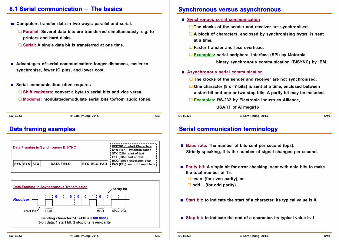
Computers transfer data in two ways: parallel and serial.
Parallel: Several data bits are transferred simultaneously e g to Parallel: Several data bits are transferred simultaneously, e.g. toprinters and hard disks.
Serial: A single data bit is transferred at one time Serial: A single data bit is transferred at one time.
Advantages of serial communication: longer distances, easier to synchronise, fewer IO pins, and lower cost.
Serial communication often requires Shift registers: convert a byte to serial bits and vice versa. Modems: modulate/demodulate serial bits to/from audio tones.
5/49ECTE333 © Lam Phung, 2014.
Synchronous versus asynchronousSynchronous versus asynchronousSynchronous serial communication The clocks of the sender and receiver are synchronised. A block of characters, enclosed by synchronising bytes, is sent
at a time. Faster transfer and less overhead. Examples: serial peripheral interface (SPI) by Motorola,
binary synchronous communication (BISYNC) by IBM.
Asynchronous serial communication The clocks of the sender and receiver are not synchronised. One character (8 or 7 bits) is sent at a time, enclosed between
a start bit and one or two stop bits. A parity bit may be included. Examples: RS-232 by Electronic Industries Alliance,
6/49ECTE333 © Lam Phung, 2014.
USART of ATmega16
Data framing examplesData framing examples
BISYNC Control CharactersSYN (16h): synchronisation
Data Framing in Synchronous BISYNC
SYN SYN STX DATA FIELD ETX BCC PAD
( ) ySTX (02h): start of textETX (03h): end of textBCC: block checksum charPAD (FFh): end of frame block( )
Data Framing in Asynchronous Transmission parity bit
1 0 0 0 0 10 0 0Receiver
Sending character “A” (41h = 0100 0001)8-bit data, 1 start bit, 2 stop bits, even-parity
start bit LSB MSB stop bits
7/49ECTE333 © Lam Phung, 2014.
, , p , p y
Serial communication terminologySerial communication terminology
Baud rate: The number of bits sent per second (bps). Strictly speaking it is the number of signal changes per secondStrictly speaking, it is the number of signal changes per second.
P it bit A i l bit f h ki t ith d t bit t kParity bit: A single bit for error checking, sent with data bits to make the total number of 1’s even (for even parity), or even (for even parity), or odd (for odd parity).
Start bit: to indicate the start of a character. Its typical value is 0.
Stop bit: to indicate the end of a character. Its typical value is 1.
8/49ECTE333 © Lam Phung, 2014.

The RSThe RS--232 standard232 standard
The RS-232 (latest revision RS-232E) is a widely used standard for fserial interfacing.
It covers four main aspects. Electrical: voltage level, rise and fall time, data rate, distance. Electrical: voltage level, rise and fall time, data rate, distance. Functional: function of each signal Mechanical: number of pins, shape & dimension of connectors.ec a ca u be o p s, s ape & d e s o o co ecto s Procedural: sequence of events for transmitting data.
9/49ECTE333 © Lam Phung, 2014.
The RSThe RS--232 standard232 standard
It defines 25-pin D connectors. In many cases, 9-pin connectors are used.
RS-232 specifies the baud rate up to 20Kbps, and the cable length up to 15m In practice it supports up to 56Kbps & 30m of shielded cablesto 15m. In practice, it supports up to 56Kbps & 30m of shielded cables.
1 2 3 4 5 5 4 3 2 11 2 3 4 5
6 7 8 9
5 4 3 2 1
9 8 7 6
10/49ECTE333 © Lam Phung, 2014.
Male DB9 connector Female DB9 connector
RSRS--232 9232 9--pin connectorpin connector
Pin Name Description1 CD Carrier Detect: DCE has detected a carrier tone
2 RXD Received Data: incoming data from DCE
3 TXD Transmit Data: outgoing data to DCE
4 DTR Data Terminal Ready: DTE is connected and turned on4 DTR Data Terminal Ready: DTE is connected and turned on
5 GND Ground
6 DSR Data Set Ready: DCE is connected and turned ony
7 RTS Request To Send: DTE has data to send
8 CTS Clear To Send: DCE can receive data
9 RI Ring Indicator: synchronised with the phone’s ringing tone
Data Terminal Equipment (DTE) essentially refers to the computer.Data Communication Equipment (DCE) essentially refers to a remote device or modem.
11/49ECTE333 © Lam Phung, 2014.
These terms are needed to explain the pin functions.
Modem connectionModem connection
Modem ADCE
Computer ADTE
CDCD
Modem BDCE
CDCD
Computer BDTE
RXDRXD
DTRTXD
DTRTXD
RXDRXD
DTRTXD
DTRTXD
Phone Line
DSRGND
DSRGND
RTSRTSDSRGND
DSRGND
RTSRTS
Phone Line
CTSCTSRIRI
CTSCTSRIRI
RS-2322 was originally used with modems to connect two PCs over the public phone lines.Wh t A h d t t d it t it RTS iWhen computer A has data to send, it assert its RTS pin.Modem A will assert its CTS when it is ready to receive.C t A t it d t th h it TXD
12/49ECTE333 © Lam Phung, 2014.
Computer A transmits data through its TXD.

NullNull--modem connectionmodem connectionF ll h d h ki bl
DTEDTERXDCD
RXDCD
Simplest cable
RXDCD
RXDCD
Full handshaking cable
DTRTXD
DTRTXD
DSRDSR
DTRTXD
DTRTXD
DSRDSR
CTSCTS
GNDGNDRTSRTS
RIRI DTEDTECTSCTS
GNDGNDRTSRTS
RIRI
RS-232 is now mainly used to connect a microcontroller with PC or
RIRI DTEDTE RIRI
peripheral devices (e.g. GPS receiver, infrared range finder, camera).This configuration is known as null-modem.Key idea: Connect pin TXD of a DTE with pin RXD of the other DTE.
13/49ECTE333 © Lam Phung, 2014.
Wire other pins to support flow control.
RSRS--232 interface and MAX232 chip232 interface and MAX232 chip
Logic RS-232 levels TTL levels1 [ 15V 3V] [+2V +5V]
Compared to TTL in computer electronics,
1 [-15V, -3V] [+2V, +5V]
0 [+3V, +15V] [0V, +0.8V]RS-232 interface uses different voltage levels.
A level converter is required between RS 232required between RS-232interface and TXD/RXD pins of microcontroller.p
MAX232 chip is often used for this purpose.
14/49ECTE333 © Lam Phung, 2014.
Serial communication Serial communication —— An An exampleexample
Bluetooth transmitter
ultrasound distance sensor
This device measures distance to the nearest obstacle
15/49ECTE333 © Lam Phung, 2014.
This device measures distance to the nearest obstacle,and transmits it via Bluetooth to PC.
Serial communication Serial communication —— An An exampleexample
ultrasounddistance sensor
Bluetooth receiver
wirelessBluetooth transmitter
serial PCUSBdistance sensor receivertransmitter
(virtual serial port)
The sensor sends data via a serial interface to Bluetooth transmitter.A Bluetooth receiver, connected to a PC, is configured as a serial port.
16/49ECTE333 © Lam Phung, 2014.
A demo, created by Adrian Herrera, is shown in the lecture.

Lecture 8’s sequenceLecture 8’s sequence
Serial communication ─ The basics8.1
Serial communication in ATmega168 2 Serial communication in ATmega168.2
Example application & Debugging tool8.3
17/49ECTE333 © Lam Phung, 2014.
8.2 Serial communication in ATmega168.2 Serial communication in ATmega16
ATmega16 has 3 subsystems for serial communication. Universal Synchronous & Asynchronous Receiver & Transmitter Universal Synchronous & Asynchronous Receiver & Transmitter
(USART) Serial Peripheral Interface (SPI) Serial Peripheral Interface (SPI) Two-wire Serial Interface (TWI)
USART: W f thi b t i thi l tWe focus on this subsystem in this lecture. Supports full-duplex mode between two devices. T i ll d i h i ti Typically used in asynchronous communication. Start bit and stop bit are used for each byte of data.
18/49ECTE333 © Lam Phung, 2014.
8.2 Serial communication in ATmega168.2 Serial communication in ATmega16Serial Peripheral Interface (SPI) The receiver and transmitter share a common clock line. Supports higher data rates. The transmitter is designated as the master, the receiver as the
slave. Examples of devices using SPI: liquid crystal display, high-speed
l t di it l tanalogue-to-digital converter.
Two-wire Serial Interface (TWI) Connect several devices such as microcontrollers and display
boards, using a two-wire bus. Up to 128 devices are supported. Each device has a unique address and can exchange data with
th d i i ll t k
19/49ECTE333 © Lam Phung, 2014.
other devices in a small network.
Serial USART Serial USART ─ An overview─ An overview
USART of the ATmega16 supports baud rates from 960bps to baud rates from 960bps to
57.6kbps, character size: 5 to 9 bits,, 1 start bit, 1 or 2 stop bits,p , optional parity bit
(even or odd parity).( p y)
Common baud rates are 19200, 9600, 4800, 2400, and 1200 bps.
20/49ECTE333 © Lam Phung, 2014.

Serial USART Serial USART ─ Block diagram─ Block diagram
c) Register UBRRto set baud rate
a) TxD and RxDpins toother device
d) Register UDRto store thesent/receivedbyte
b) Registers toconfigure/monitor
21/49ECTE333 © Lam Phung, 2014.
USART
Serial USART Serial USART ─ Hardware elements─ Hardware elementsUSART Clock Generator: to provide clock source. to set baud rate using UBRR register.
USART Transmitter:USART Transmitter: to send a character through TxD pin. to handle start/stop bit framing, parity bit, shift register. to handle start/stop bit framing, parity bit, shift register.
USART Receiver: to receive a character through RxD pin. to perform the reverse operation of the transmitter.
USART Registers: to configure control and monitor the serial USART
22/49ECTE333 © Lam Phung, 2014.
to configure, control, and monitor the serial USART.
Serial USART Serial USART ─ Three groups of registers─ Three groups of registers
USART Baud Rate Registers UBRRH and UBRRL
USART Control and Status Registers UCSRA UCSRB UCSRC
USART Data Registers UDR
Understanding these registers is essential in using the serial port. Therefore, we’ll study these registers in depth.
23/49ECTE333 © Lam Phung, 2014.
, y g p
USART Baud Rate RegistersUSART Baud Rate RegistersTwo 8-bit registers together define the baud rate.
012345670
89101112131415URSEL 0
register UBRRLregister UBRRH
URSEL
1) (UBRR 16(Hz) frequency clock system rate baud
+×=
(Hz)frequencyclocksystem
Example: Find UBRR registers for baud rate of 1200bps assuming
1rate baud 16
(Hz)frequencyclocksystemUBRR −×
=
Example: Find UBRR registers for baud rate of 1200bps, assuming system clock is 1MHz. UBRR = 1000000/(16 × 1200) ─ 1 = 51d = 0033H UBRR 1000000/(16 × 1200) 1 51d 0033H. Therefore, UBRRH = 00H and UBRRL = 33H. C code: UBRRH = 0x00; UBRRL = 0x33;
24/49ECTE333 © Lam Phung, 2014.
C code: UBRRH = 0x00; UBRRL = 0x33;

USART Control and Status Register A: USART Control and Status Register A: UCSRAUCSRA
RXC TXC UDRE FE DOR PE U2X MPCM
01234567
RXC TXC UDRE FE DOR PE U2X MPCM
1 d bl h i i d
1 to enable multi-processor com mode
1 when there is parity error
1 to double the transmission speed
1 when there is frame error
1 when there is data overun
1 when USART data register is empty
1 when there is frame error
1 when no new data in transmit buffer (tx complete)
1 when receive buffer has unread data (rx complete)
25/49ECTE333 © Lam Phung, 2014.
USART Control and Status Register B: USART Control and Status Register B: UCSRBUCSRB
RXCIE TXCIE UDRIE RXEN TXEN UCSZ2 RXB8 TXB8
01234567
R d bi f 9 bi h i
Tx extra data bit for 9-bit character size
bit UCSZ2 to decide character size
Rx extra data bit for 9-bit character size
1 to enable USART receiver: Pin D 0 = RXD pin
1 to enable USART transmitter: Pin D.1 = TXD pin
1 to enable USART Data Register Empty Interrupt
1 to enable USART receiver: Pin D.0 = RXD pin
1 to enable TX Complete Interrupt, valid only if Global Interrupt Flag = 1 and TXC = 1
1 to enable RX Complete Interrupt, valid only if Global Interrupt Flag = 1 and RXC = 1
26/49ECTE333 © Lam Phung, 2014.
USART Control and Status Register C: USART Control and Status Register C: UCSRCUCSRC
URSEL UMSEL UPM1 UPM0 USBS UCSZ1 UCSZ0 UCPOL
01234567
Clock polarity, used with synchronous
Used with UCSZ2 to select character size
To select stop bit modes: 0 1 stop bit, 1 2 stop bits
To select parity mode: 00 no parity 10 even party 11 odd parity
To select USART modes: 0 asynchronous, 1 synchronous
To select parity mode: 00 no parity, 10 even party, 11 odd parity
Must be set to 1 to write to UCSRC. Note: UCSRC and UBRRH share same location.
27/49ECTE333 © Lam Phung, 2014.
Setting character sizeSetting character sizeCharacter size (5, 6, 7, 8, 9) is determined by three bits bit UCSZ2 (in register UCSRB), bit UCSZ1 and bit UCSZ0 (in register UCSRC).
Example: For a character size of 8 bits we setExample: For a character size of 8 bits, we setUCSZ2 = 0, UCSZ1 = 1, and UCSZ0 = 1.
UCSZ2 UCSZ1 UCSZ0 Character SizeUCSZ2 UCSZ1 UCSZ0 Character Size
0 0 0 5-bit
0 0 1 6-bit
0 1 0 7-bit
0 1 1 8-bit
1 0 0 Reserved1 0 0 Reserved
1 0 1 Reserved
1 1 0 Reserved
28/49ECTE333 © Lam Phung, 2014.
1 1 1 9-bit
USART Data RegisterUSART Data Register
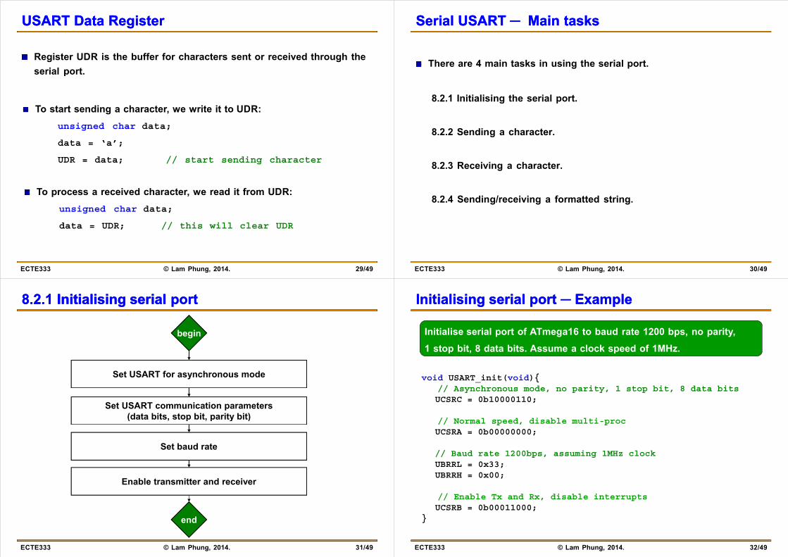
Register UDR is the buffer for characters sent or received through the serial portserial port.
T t t di h t it it t UDRTo start sending a character, we write it to UDR:unsigned char data;
data = ‘a’;
UDR = data; // start sending character
To process a received character, we read it from UDR: i d h d tunsigned char data;
data = UDR; // this will clear UDR
29/49ECTE333 © Lam Phung, 2014.
Serial USART Serial USART ─ ─ Main tasksMain tasks
There are 4 main tasks in using the serial port.
8.2.1 Initialising the serial port.
8.2.2 Sending a character.
8.2.3 Receiving a character.
8.2.4 Sending/receiving a formatted string.
30/49ECTE333 © Lam Phung, 2014.
8.2.1 8.2.1 InitialisingInitialising serial portserial port
begin
Set USART for asynchronous mode
Set USART communication parameters(data bits stop bit parity bit)(data bits, stop bit, parity bit)
Set baud rate
Enable transmitter and receiver
end
31/49ECTE333 © Lam Phung, 2014.
end
InitialisingInitialising serial port ─ Exampleserial port ─ Example
Initialise serial port of ATmega16 to baud rate 1200 bps, no parity, 1 stop bit 8 data bits Assume a clock speed of 1MHz
void USART_init(void){
1 stop bit, 8 data bits. Assume a clock speed of 1MHz.
// Asynchronous mode, no parity, 1 stop bit, 8 data bitsUCSRC = 0b10000110;
// i i// Normal speed, disable multi-procUCSRA = 0b00000000;
// B d t 1200b i 1MH l k// Baud rate 1200bps, assuming 1MHz clockUBRRL = 0x33;UBRRH = 0x00;
// Enable Tx and Rx, disable interruptsUCSRB = 0b00011000;
}
32/49ECTE333 © Lam Phung, 2014.
}
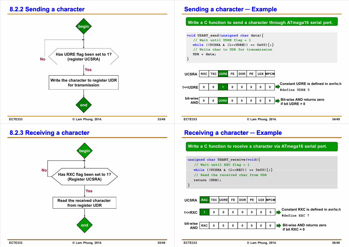
8.2.2 8.2.2 Sending a characterSending a character
begin
Has UDRE flag been set to 1?(register UCSRA)No
Yes
Write the character to register UDRfor transmission
end
33/49ECTE333 © Lam Phung, 2014.
Sending a character Sending a character ─ Example─ Example
Write a C function to send a character through ATmega16 serial port.
void USART_send(unsigned char data){
// Wait until UDRE flag = 1
while ((UCSRA & (1<<UDRE)) == 0x00){;}
// Write char to UDR for transmission
UDR = data;
}
RXC TXC UDRE FE DOR PE U2X MPCMUCSRA
Constant UDRE is defined in avr/io.h#define UDRE 5
0 0 1 0 0 0 0 01<<UDRE
0 0 UDRE 0 0 0 0 0bit-wise
ANDBit-wise AND returns zero if bit UDRE = 0
34/49ECTE333 © Lam Phung, 2014.
8.2.3 Receiving a 8.2.3 Receiving a charactercharacter
begin
NoHas RXC flag been set to 1?
(Register UCSRA)
No
Read the received character
Yes
Read the received characterfrom register UDR
end
35/49ECTE333 © Lam Phung, 2014.
Receiving a character Receiving a character ─ Example─ Example
Write a C function to receive a character via ATmega16 serial port.
unsigned char USART_receive(void){
// Wait until RXC flag = 1
while ((UCSRA & (1<<RXC)) == 0x00){;}while ((UCSRA & (1<<RXC)) == 0x00){;}
// Read the received char from UDR
return (UDR);
}}
RXC TXC UDRE FE DOR PE U2X MPCMUCSRA RXC TXC UDRE FE DOR PE U2X MPCMUCSRA
Constant RXC is defined in avr/io.h#define RXC 7
1 0 0 0 0 0 0 01<<RXC
RXC 0 0 0 0 0 0 0bit-wiseAND
Bit-wise AND returns zero if bit RXC = 0
#define RXC 7
36/49ECTE333 © Lam Phung, 2014.
if bit RXC 0

8.2.4 Sending/receiving a formatted string8.2.4 Sending/receiving a formatted string
In ANSI C, the header file <stdio.h> has two functions for formatted strings: printf and scanf.g p
Function printf sends a formatted string to the standard output device, which is usually the video display.unsigned char a, b;
a = 2; b = 3;
printf(“first = %d, second = %d, sum = %d”, a, b, a + b);
Function scanf reads a formatted string from the standard input device, which is usually the keyboard.unsigned char a, b;
scanf(“%d %d”, &a, &b); // get integers a, b from input string
37/49ECTE333 © Lam Phung, 2014.
Sending/receiving formatted stringsSending/receiving formatted strings
Being able to send/receive formatted strings through a serial port is useful in microcontroller applications.
To this end, we configure the serial port as the standard input and output devices.
General steps:
1) Write two functions to send and receive a character via serial port.
2) In main(), call fdevopen() to set the two functions as the handlers for standard output and input devices.
3) Use printf/scanf as usual. Formatted strings will be sent/received via serial port.
38/49ECTE333 © Lam Phung, 2014.
Sending/receiving formatted strings Sending/receiving formatted strings ─ Example─ Example#include <avr/io.h>#include <stdio.h>
int USART_send(char c, FILE *stream){// wait until UDRE flag is set to logic 1// wait until UDRE flag is set to logic 1while ((UCSRA & (1<<UDRE)) == 0x00){;}UDR = c; // Write character to UDR for transmission
}
int USART_receive(FILE *stream){// wait until RXC flag is set to logic 1while ((UCSRA & (1<<RXC)) == 0x00){;}return (UDR); // Read the received character from UDR
}}
int main(void){unsigned char a;
// Code to initialise baudrate TXD RXD and so on is not shown here// … Code to initialise baudrate, TXD, RXD, and so on is not shown here
// Initialise the standard IO handlersstdout = fdevopen(USART_send, NULL);stdin = fdevopen(NULL, USART_receive);
// Start using printf, scanf as usualwhile (1){
printf(“\n\rEnter a = ");scanf(“%d”, &a); printf(“%d”, a);
}
39/49ECTE333 © Lam Phung, 2014.
}}
AVR Demo: Remote controller for carAVR Demo: Remote controller for car
ECTE350 Third-prize Trade Fair 2010.
ZigBee, accelerometer, ATmega16
(J d Ch d i k t l )
40/49ECTE333 © Lam Phung, 2014.
(Jarod Chadwick et al.)
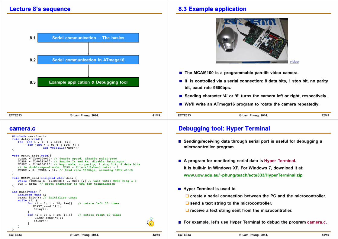
Lecture 8’s sequenceLecture 8’s sequence
Serial communication ─ The basics8.1
Serial communication in ATmega168 2 Serial communication in ATmega168.2
Example application & Debugging tool8.3
41/49ECTE333 © Lam Phung, 2014.
8.3 Example application8.3 Example application
The MCAM100 is a programmable pan-tilt video camera.
video
p g p
It is controlled via a serial connection: 8 data bits, 1 stop bit, no parity bit, baud rate 9600bps.bit, baud rate 9600bps.
Sending character ‘4’ or ‘6’ turns the camera left or right, respectively.
W ’ll it AT 16 t t t th t dl
42/49ECTE333 © Lam Phung, 2014.
We’ll write an ATmega16 program to rotate the camera repeatedly.
camera.ccamera.c#include <avr/io h>#include <avr/io.h>void delay(void){
for (int i = 0; i < 1000; i++) for (int j = 0; j < 100; j++)
asm volatile("nop");}}
void USART_init(void){UCSRA = 0b00000010; // double speed, disable multi-procUCSRB = 0b00011000; // Enable Tx and Rx, disable interruptsUCSRC = 0b10000110; // Asyn mode, no parity, 1 stop bit, 8 data bitsUCSRC = 0b10000110; // Asyn mode, no parity, 1 stop bit, 8 data bits// in double-speed mode, UBRR = Fclock/(8xbaud rate) - 1UBRRH = 0; UBRRL = 12; // Baud rate 9600bps, assuming 1MHz clock
}
void USART send(unsigned char data){_ g {while ((UCSRA & (1<<UDRE)) == 0x00){;} // wait until UDRE flag = 1UDR = data; // Write character to UDR for transmission
}
int main(void) {i d h iunsigned char i;
USART_init(); // initialise USARTwhile (1) {
for (i = 0; i < 10; i++){ // rotate left 10 timesUSART_send('4');d l ()delay();
}for (i = 0; i < 10; i++){ // rotate right 10 times
USART_send('6');delay();
}
43/49ECTE333 © Lam Phung, 2014.
}}
}
Debugging tool: Hyper TerminalDebugging tool: Hyper Terminal
Sending/receiving data through serial port is useful for debugging a microcontroller program.
A program for monitoring serial data is Hyper Terminal.It is built-in in Windows XP. For Windows 7, download it at:www.uow.edu.au/~phung/teach/ecte333/HyperTerminal.zip
Hyper Terminal is used to create a serial connection between the PC and the microcontroller. send a text string to the microcontroller. receive a text string sent from the microcontroller.
For example let’s use Hyper Terminal to debug the program camera c
44/49ECTE333 © Lam Phung, 2014.
For example, let s use Hyper Terminal to debug the program camera.c.
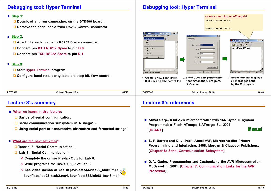
Debugging tool: Hyper TerminalDebugging tool: Hyper Terminal
Step 1: Download and run camera.hex on the STK500 board. Remove the serial cable from RS232 Control connector.
Step 2:Step 2: Attach the serial cable to RS232 Spare connector. Connect pin RXD RS232 Spare to pin D 0 Connect pin RXD RS232 Spare to pin D.0. Connect pin TXD RS232 Spare to pin D.1.
Step 3: Start Hyper Terminal program. Start Hyper Terminal program. Configure baud rate, parity, data bit, stop bit, flow control.
45/49ECTE333 © Lam Phung, 2014.
Debugging tool: Hyper TerminalDebugging tool: Hyper Terminal
camera.c running on ATmega16:USART_send('4');
…
USART_send('6');
1. Create a new connectionthat uses a COM port of PC
2. Enter COM port parametersthat match the C program,
3. HyperTerminal displaysall messages sent
46/49ECTE333 © Lam Phung, 2014.
& Connect by the C program.
Lecture 8’s summaryLecture 8’s summary
What we learnt in this lecture: Basics of serial communication. Serial communication subsystem in ATmega16. Using serial port to send/receive characters and formatted strings.
What are the next activities? Tutorial 8: ‘Serial Communication’ . Lab 8: ‘Serial Communication’
Complete the online Pre-lab Quiz for Lab 8. Write programs for Tasks 1, 2, 3 of Lab 8. See video demos of Lab 8: [avr]/ecte333/lab08_task1.mp4
[avr]/labs/lab08_task2.mp4, [avr]/ecte333/lab08_task3.mp4
47/49ECTE333 © Lam Phung, 2014.
Lecture 8’s referencesLecture 8’s references
Atmel Corp 8-bit AVR microcontroller with 16K Bytes In-SystemAtmel Corp., 8-bit AVR microcontroller with 16K Bytes In-System Programmable Flash ATmega16/ATmega16L, 2007,[USART].[ ]
S. F. Barrett and D. J. Pack, Atmel AVR Microcontroller Primer: Programming and Interfacing, 2008, Morgan & Claypool Publishers, [Chapter 8: Serial Communication Subsystem].
D. V. Gadre, Programming and Customizing the AVR Microcontroller, McGraw-Hill 2001 [Chapter 7: Communication Links for the AVRMcGraw-Hill, 2001, [Chapter 7: Communication Links for the AVR Processor].
48/49ECTE333 © Lam Phung, 2014.
Lecture 8’s referencesLecture 8’s references
M. Mazidi, J. Mazidi, R. McKinlay, “The 8051 microcontroller and embedded systems using assembly and C ” 2nd ed Pearsonembedded systems using assembly and C, 2 ed., PearsonPrentice Hall, 2006, [Chapters 10].
M. Mazidi and J. Mazidi, “The 8086 IBM PC and compatible computers,” 4th ed., Pearson Prentice Hall, 2003, [Chapters 17].
P. Spasov, “Microcontroller technology the 68HC11,” 3rd ed., Prentice Hall 1999 [Chapters 10]Prentice Hall, 1999, [Chapters 10].
H Huang “MC68HC12 an introduction: software and hardwareH. Huang, MC68HC12 an introduction: software and hardwareinterfacing,” Thomson Delmar Learning, 2003, [Chapter 9].
49/49ECTE333 © Lam Phung, 2014.