Embed Size (px)
Citation preview
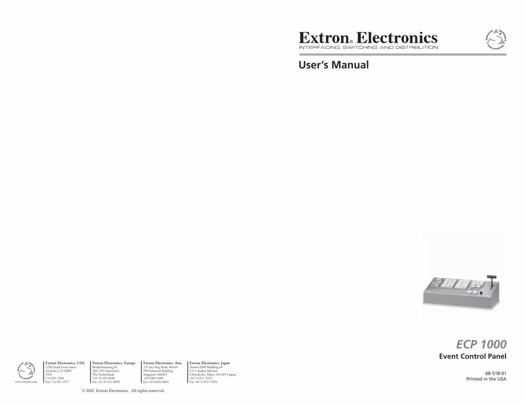
User’s Manual
Extron Electronics, USA1230 South Lewis StreetAnaheim, CA 92805USA714.491.1500 Fax 714.491.1517
Extron Electronics, EuropeBeeldschermweg 6C3821 AH AmersfoortThe Netherlands+31.33.453.4040 Fax +31.33.453.4050
Extron Electronics, Asia135 Joo Seng Road, #04-01PM Industrial BuildingSingapore 368363+65.6383.4400 Fax +65.6383.4664
Extron Electronics, JapanDaisan DMJ Building 6F3-9-1 Kudan MinamiChiyoda-ku, Tokyo 102-0074 Japan +81.3.3511.7655 Fax +81.3.3511.7656www.extron.com
© 2002 Extron Electronics. All rights reserved.
Event Control Panel
68-518-01Printed in the USA
ECP 1000

iECP 1000 • Table of Contents
Chapter 1 • Introduction .......................................................... 1-1
Features ...................................................................................... 1-2
Chapter 2 • Installation ............................................................. 2-1
Rear Panel Features ............................................................. 2-2
Installation ............................................................................... 2-2
Chapter 3 • Operation ................................................................ 3-1
Top Panel Controls ................................................................. 3-2
Power-up .................................................................................... 3-3
Using the Menus ..................................................................... 3-4Changing the backlight intensity .......................................... 3-4Performing a system reset .................................................... 3-5Programming the ECP 1000 .................................................. 3-5
Applying a Switch ................................................................. 3-6Applying a cut ........................................................................ 3-6Applying a dissolve ................................................................. 3-7Applying a title....................................................................... 3-7Wipes ...................................................................................... 3-8
Applying a wipe ................................................................... 3-10
Chapter 4 • Control Software for Windows ............... 4-1
Installing the Software ...................................................... 4-2
Starting the Software ......................................................... 4-2
Appendix • Reference Information .................................. A-1
Maintenance and Upgrades ............................................ A-2Cleaning the filter fan .......................................................... A-2Installing a firmware update ............................................... A-3Replacing keycap labels ........................................................ A-5
Specifications ......................................................................... A-5
Part Numbers .......................................................................... A-6
Table of Contents
68-518-01 Rev. BPrinted in the USA
04 02

ii ECP 1000 • Table of Contents
Table of Contents, cont’d
ECP 1000 Event Control Panel
1Chapter One
Introduction
Features
ECP 1000 • Introduction
Introduction, cont’d
ECP 1000 Event Control Panel
2Chapter Two
Installation
Rear Panel Features
Installation
Introduction
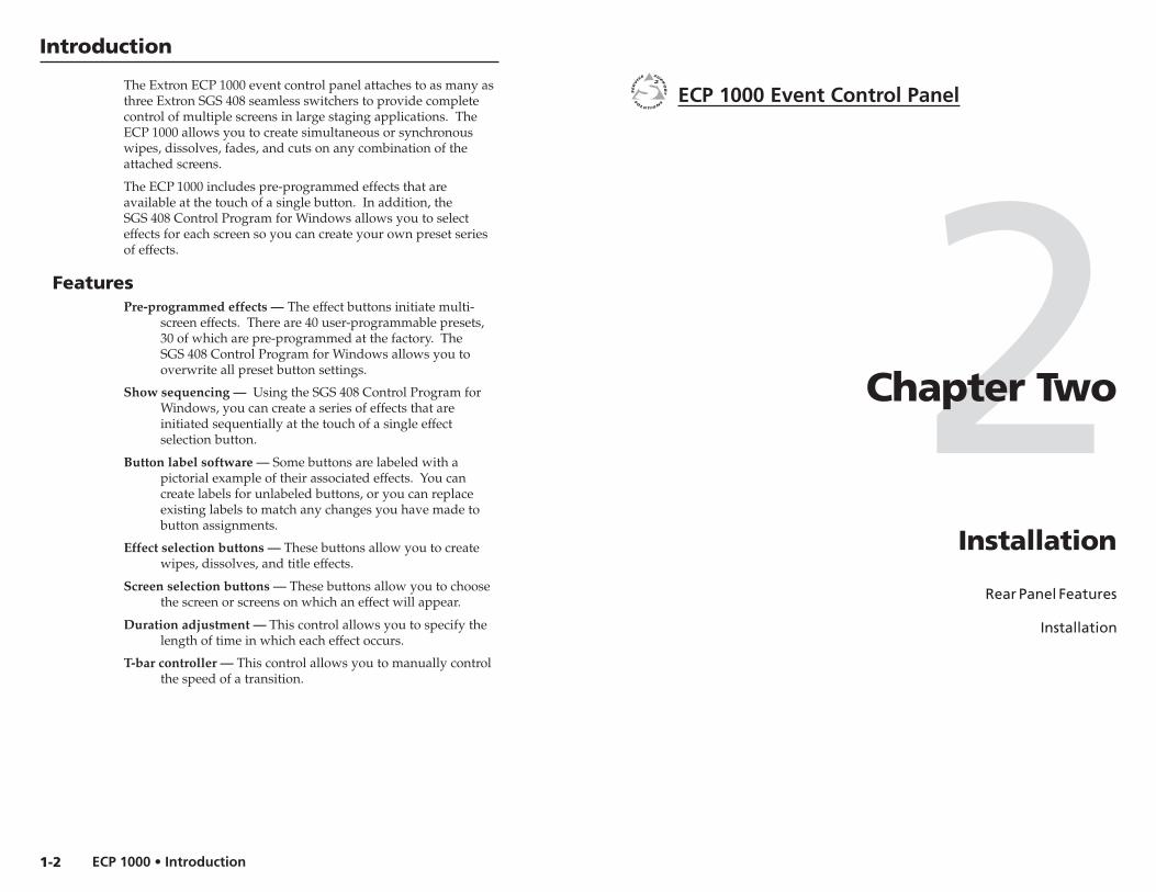
The Extron ECP 1000 event control panel attaches to as many asthree Extron SGS 408 seamless switchers to provide completecontrol of multiple screens in large staging applications. TheECP 1000 allows you to create simultaneous or synchronouswipes, dissolves, fades, and cuts on any combination of theattached screens.
The ECP 1000 includes pre-programmed effects that areavailable at the touch of a single button. In addition, theSGS 408 Control Program for Windows allows you to selecteffects for each screen so you can create your own preset seriesof effects.
FeaturesPre-programmed effects — The effect buttons initiate multi-
screen effects. There are 40 user-programmable presets,30 of which are pre-programmed at the factory. TheSGS 408 Control Program for Windows allows you tooverwrite all preset button settings.
Show sequencing — Using the SGS 408 Control Program forWindows, you can create a series of effects that areinitiated sequentially at the touch of a single effectselection button.
Button label software — Some buttons are labeled with apictorial example of their associated effects. You cancreate labels for unlabeled buttons, or you can replaceexisting labels to match any changes you have made tobutton assignments.
Effect selection buttons — These buttons allow you to createwipes, dissolves, and title effects.
Screen selection buttons — These buttons allow you to choosethe screen or screens on which an effect will appear.
Duration adjustment — This control allows you to specify thelength of time in which each effect occurs.
T-bar controller — This control allows you to manually controlthe speed of a transition.
1-2
ECP 1000 • InstallationECP 1000 • Installation
Installation, cont’d
2-3
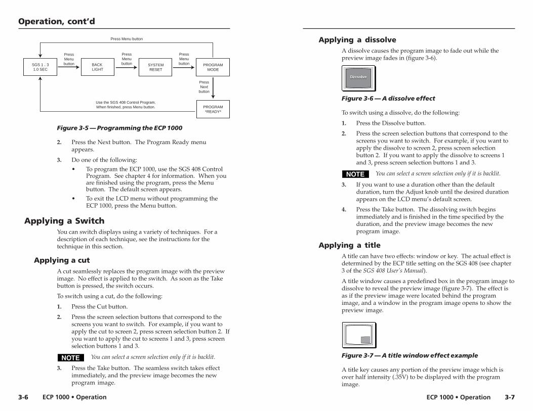
5 Continue the procedure for installing the SGS 408.
6 Attach power cords and plug the SGS 408 seamlessswitcher, ECP 1000 event control panel, input devices, andoutput devices into a grounded AC source.
7 Select an input from the front panel buttons on theSGS 408 switcher or RCP 1000 remote control unit.
8 The image should now appear. If not, ensure that alldevices are plugged in and receiving power. Check thecabling and make adjustments as needed. Select adifferent input to check for a display.
Figure 2-2 — SGS 408 and ECP 1000 application
Installation
Rear Panel Features
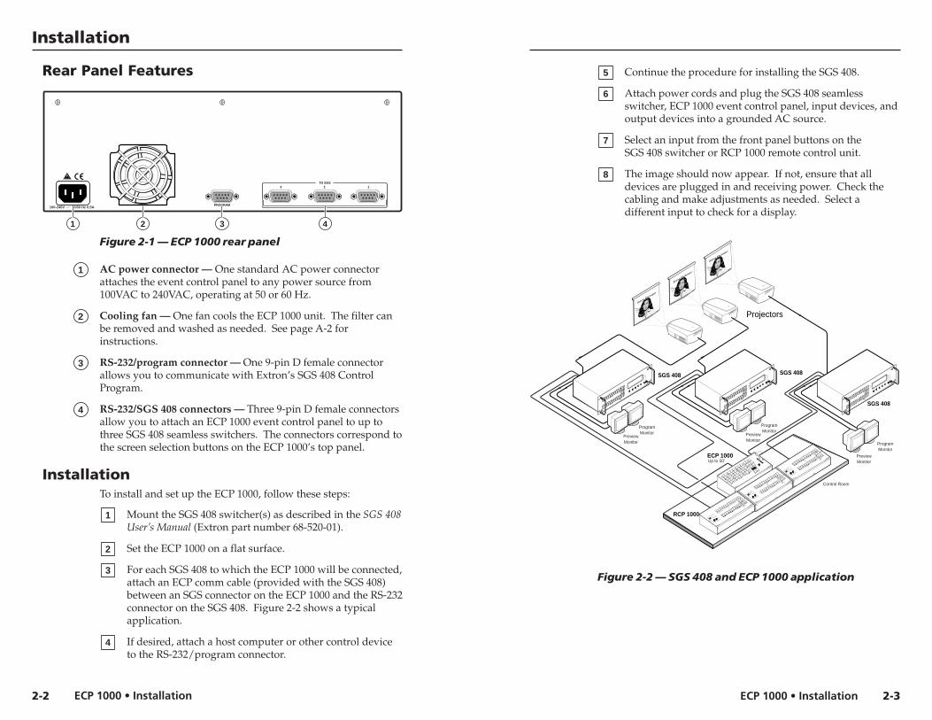
Figure 2-1 — ECP 1000 rear panel
1 AC power connector — One standard AC power connectorattaches the event control panel to any power source from100VAC to 240VAC, operating at 50 or 60 Hz.
2 Cooling fan — One fan cools the ECP 1000 unit. The filter canbe removed and washed as needed. See page A-2 forinstructions.
3 RS-232/program connector — One 9-pin D female connectorallows you to communicate with Extron’s SGS 408 ControlProgram.
4 RS-232/SGS 408 connectors — Three 9-pin D female connectorsallow you to attach an ECP 1000 event control panel to up tothree SGS 408 seamless switchers. The connectors correspond tothe screen selection buttons on the ECP 1000’s top panel.
InstallationTo install and set up the ECP 1000, follow these steps:
1 Mount the SGS 408 switcher(s) as described in the SGS 408User’s Manual (Extron part number 68-520-01).
2 Set the ECP 1000 on a flat surface.
3 For each SGS 408 to which the ECP 1000 will be connected,attach an ECP comm cable (provided with the SGS 408)between an SGS connector on the ECP 1000 and the RS-232connector on the SGS 408. Figure 2-2 shows a typicalapplication.
4 If desired, attach a host computer or other control deviceto the RS-232/program connector.
2-2
Control Room
ECP 1000
RCP 1000
ECP 1000
EVENT CONTROL PANEL
SCREEN
ADJUST
SGS 408
PROGRAM
FREEZEBLACK
1
2
3
4
5
6
7
8
CUT
TAKEPROGRAM
PREVIEW
OUTPUT RATE
EFFECT
TRANSITION
SGS 408
SEAMLESS GRAPHIC SWITCHER INPUT
1
2
3
4
TRANSITIONS
EFFECTS
RCP COMMUNICATION
PREVIEW
FREEZEBLACK
1
2
3
4
5
6
7
8
Tx
Rx
Projectors
SGS 408
PROGRAM
FREEZEBLACK
1
2
3
4
5
6
7
8
CUT
TAKEPROGRAM
PREVIEW
OUTPUT RATE
EFFECT
TRANSITION
SGS 408
SEAMLESS GRAPHIC SWITCHER INPUT
1
2
3
4
TRANSITIONS
EFFECTS
RCP COMMUNICATION
PREVIEW
FREEZEBLACK
1
2
3
4
5
6
7
8
Tx
Rx
PreviewMonitor
Up to 50'
ProgramMonitor
PreviewMonitor
ProgramMonitor
SGS 408
PROGRAM
FREEZEBLACK
1
2
3
4
5
6
7
8
CUT
TAKEPROGRAM
PREVIEW
OUTPUT RATE
EFFECT
TRANSITION
SGS 408
SEAMLESS GRAPHIC SWITCHER INPUT
1
2
3
4
TRANSITIONS
EFFECTS
RCP COMMUNICATION
PREVIEW
FREEZEBLACK
1
2
3
4
5
6
7
8
Tx
Rx
PreviewMonitor
ProgramMonitor
RCP 1000
REMOTE CONTROL PANEL
PROGRAM
FREEZE
BLACK
1
2
3
4
5
6
7
8
PPREVIEW
FREEZE
BLACK
1
2
3
4
5
6
7
8
VERT
HORZ
CONT
BRIGHT
CENTERSIZE
FILTERCOND/BRIGHT
TRANSITIONS
EFFECTS
COMMUNICATION
TxRx
RCP 1000
REMOTE CONTROL PANEL
PROGRAM
FREEZE
BLACK
1
2
3
4
5
6
7
8
PPREVIEW
FREEZE
BLACK
1
2
3
4
5
6
7
8
VERT
HORZ
CONT
BRIGHT
CENTERSIZE
FILTERCOND/BRIGHT
TRANSITIONS
EFFECTS
COMMUNICATION
TxRx
RCP 1000
REMOTE CONTROL PANEL
PROGRAM
FREEZE
BLACK
1
2
3
4
5
6
7
8
PPREVIEW
FREEZE
BLACK
1
2
3
4
5
6
7
8
VERT
HORZ
CONT
BRIGHT
CENTERSIZE
FILTERCOND/BRIGHT
TRANSITIONS
EFFECTS
COMMUNICATION
TxRx
100-240V 50/60 Hz 0.5A
TO SGS
PROGRAM
3 2 1
1 2 3 4

ECP 1000 • Installation
Installation, cont’d
ECP 1000 Event Control Panel
3Chapter Three
Operation
Top Panel Controls
Power-up
Using the Menus
Applying a Switch
2-4

ECP 1000 • OperationECP 1000 • Operation
Operation, cont’dOperation
3-2 3-3
Top Panel Controls
Figure 3-1 — ECP 1000 top panel
1 One-screen effect buttons — Allow you to specify the effects forone screen. All of the buttons are user-programmable.
2 Two-screen effect buttons — Allow you to specify the effectsfor two screens. The buttons in the two right columns are pre-programmed. All of the buttons are user-programmable.
3 Three-screen effect buttons — Allow you to specify the effectsfor three screens. The buttons in the two right columns are pre-programmed. All of the buttons are user-programmable.
The names “one-screen”, “two-screen”, and “three-screen” are not absolutes. You can program a one-screeneffect into a three-screen effect button. The names areused only to identify the particular set of buttons.
4 Soft edge button — Allows you to select whether single-dimension wipes will have hard or soft edges.
5 Screen selection buttons — Allow you to choose the screen onwhich effects, cuts, dissolves, and titles will take place.
6 Cut button — Initiates an immediate seamless switch betweenthe program and preview images. See “Applying a cut” on page3-6 for more information.
7 Dissolve button — Allows you to set up a dissolving switch.See “Applying a dissolve” on page 3-7 for more information.
8 Title button — Allows you to set up a title switch. See“Applying a title” on page 3-7 for more information.
9 Take button — Initiates the switch selected by the effectbuttons.
10 T-bar controller — Allows you to override the duration of aneffect. See step 4 in “Applying a title” on page 3-8 or step 5 in“Applying a wipe” on page 3-10.
11 Adjustment knob — Allows you to make adjustments to themenu selections (see “Using the Menus” on page 3-4) and tochange the duration of an effect (see “Applying a Switch” onpage 3-6.
12 LCD screen — Displays status information and menu screens.
13 Next button — Steps through LCD screens within a menu. See“Using the Menus” on page 3-4.
14 Menu button — Steps through LCD menus. See “Using theMenus” on page 3-4.
Power-upWhen the ECP 1000 is powered up, the following events occur:
• All lights on the ECP 1000 front panel turn on and then off, insequence.
• The ECP 1000 detects the number of SGS 408 units that areconnected.
• The buttons that are programmed to work with the number ofconnected SGS 408 units become backlit. For example, ifSGS 408 units are attached to SGS ports 1 and 3, all screeneffect buttons that are programmed to work with 1 or 2screens become backlit, as do screen selection buttons 1and 3.
• The LCD displays the name of the product, and then displaysthe attached screens (based on the connected ports) andthe default effect duration (figure 3-2). This second screenis the default screen.
Figure 3-2 — Power-up screens
EXTRONECP-1000
SGS 1 . 31.0 SEC
ECP 1000EVENT CONTROL PANEL
SCREEN
ADJUST
TITLE
SOFTEDGE
DISSOLVE
1 2 3
CUT
TAKE
MENU NEXT
1 6 7 8 942
10
11
121314
53

ECP 1000 • OperationECP 1000 • Operation
Operation, cont’d
In the display of attached screens, a dot represents ascreen that is not attached.
Using the MenusThe ECP 1000 menus allow you to do the following:
• Change the backlight intensity (see below).
• Perform a system reset (see page 3-5).
• Program the ECP 1000 (see page 3-5).
Changing the backlight intensityThe buttons on the top panel of the ECP 1000 are backlit tomake them easier to see in rooms with low-level lighting. Youcan control the amount of light the buttons emit by doing thefollowing:
1. From the default screen, press the Menu button. The BackLight menu appears (figure 3-3).
Figure 3-3 — Changing the backlight
2. Press the Next button. The Intensity screen appears.
3. Rotate the Adjust knob until the backlight is at the desiredintensity.
4. Do one of the following:
• To exit the LCD menu, press the Menu button threetimes. The default screen appears.
• To proceed to the System Reset menu, press theMenu button once.
• To return to the Back Light menu, press the Nextbutton once.
Performing a system resetA system reset returns all settings to their factory defaults. Itremoves all user-programmed effects, and returns pre-programmed effect buttons to their original effects. It alsocancels the screen selection button settings.
To perform a system reset, do the following:
1. From the default screen, press the Menu button twice. TheSystem Reset menu appears (figure 3-4).
Figure 3-4 — Performing a system reset
2. Press the Next button. The Take to Confirm menuappears.
3. Do one of the following:
• To confirm the system reset, press the Take button.The system reset occurs, and the default screenappears.
• To cancel the system reset and exit the LCD menu,press the Menu button twice. The default screenappears.
• To proceed to the Program Mode menu, press theMenu button once.
Programming the ECP 1000When the ECP 1000 is in program mode, it cannotcontrol effects on the SGS 408.
The SGS 408 Control Program allows you to program theECP 1000. Before the software can communicate with theECP 1000, the ECP 1000 must be in program mode. To enterprogram mode, do the following:
1. From the default screen, press the Menu button threetimes. The Program Mode menu appears (figure 3-5 onthe next page).
3-4 3-5
SGS 1 . 31.0 SEC
BACK LIGHT
PressMenubutton
TAKE TOCONFIRM
PressNext
button
Press Take button
Press Menu button twice
SYSTEMRESET
PressMenubutton PROGRAM
MODE
PressMenubutton
PressNext
button
PressMenubutton(System
resetoccurs)
(Systemresetdoesnot
occur)
SGS 1 . 31.0 SEC
BACK LIGHT
PressMenubutton
INTENSITY20%
INTENSITY30%
PressNext
button
RotateAdjustknob
SYSTEMRESET
PressMenubutton
PressNext
button
PressMenubutton
PressMenubuttonthreetimes
ECP 1000 • OperationECP 1000 • Operation
Operation, cont’d
Figure 3-5 — Programming the ECP 1000
2. Press the Next button. The Program Ready menuappears.
3. Do one of the following:
• To program the ECP 1000, use the SGS 408 ControlProgram. See chapter 4 for information. When youare finished using the program, press the Menubutton. The default screen appears.
• To exit the LCD menu without programming theECP 1000, press the Menu button.
Applying a SwitchYou can switch displays using a variety of techniques. For adescription of each technique, see the instructions for thetechnique in this section.
Applying a cutA cut seamlessly replaces the program image with the previewimage. No effect is applied to the switch. As soon as the Takebutton is pressed, the switch occurs.
To switch using a cut, do the following:
1. Press the Cut button.
2. Press the screen selection buttons that correspond to thescreens you want to switch. For example, if you want toapply the cut to screen 2, press screen selection button 2. Ifyou want to apply the cut to screens 1 and 3, press screenselection buttons 1 and 3.
You can select a screen selection only if it is backlit.
3. Press the Take button. The seamless switch takes effectimmediately, and the preview image becomes the newprogram image.
SGS 1 . 31.0 SEC
BACK LIGHT
PressMenubutton
PROGRAM*READY*
PressNext
button
Use the SGS 408 Control Program.When finished, press Menu button.
SYSTEMRESET
PressMenubutton
Press Menu button
PROGRAMMODE
PressMenubutton
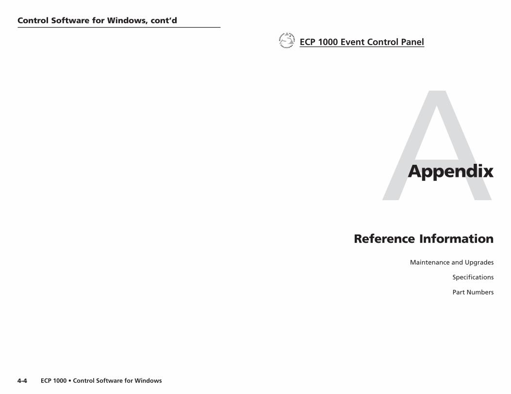
Applying a dissolveA dissolve causes the program image to fade out while thepreview image fades in (figure 3-6).
Figure 3-6 — A dissolve effect
To switch using a dissolve, do the following:
1. Press the Dissolve button.
2. Press the screen selection buttons that correspond to thescreens you want to switch. For example, if you want toapply the dissolve to screen 2, press screen selectionbutton 2. If you want to apply the dissolve to screens 1and 3, press screen selection buttons 1 and 3.
You can select a screen selection only if it is backlit.
3. If you want to use a duration other than the defaultduration, turn the Adjust knob until the desired durationappears on the LCD menu’s default screen.
4. Press the Take button. The dissolving switch beginsimmediately and is finished in the time specified by theduration, and the preview image becomes the newprogram image.
Applying a titleA title can have two effects: window or key. The actual effect isdetermined by the ECP title setting on the SGS 408 (see chapter3 of the SGS 408 User’s Manual).
A title window causes a predefined box in the program image todissolve to reveal the preview image (figure 3-7). The effect isas if the preview image were located behind the programimage, and a window in the program image opens to show thepreview image.
Figure 3-7 — A title window effect example
A title key causes any portion of the preview image which isover half intensity (.35V) to be displayed with the programimage.
3-6 3-7
DissolveDissolve

ECP 1000 • OperationECP 1000 • Operation
Operation, cont’d
When the either title effect ends, the preview image disappears,and the program image is again intact.
To apply a title, do the following:
1. Press the Title button.
2. Press the screen selection buttons that correspond to thescreens you want to switch. For example, if you want toapply the title to screen 2, press screen selection button 2.If you want to apply the title to screens 1 and 3, pressscreen selection buttons 1 and 3.
You can select a screen selection only if it is backlit.
3. If you want to use a duration other than the defaultduration, turn the Adjust knob until the desired durationappears on the LCD menu’s default screen.
4. Do one of the following.
• Press the Take button. During the time specified bythe duration, the selected portion of the programimage dissolves away to be replaced by the previewimage. The Take button remains lit, and the Titlebutton flashes.
When you want to end the title, press the Take buttonagain.
• Move the T-bar control. The title appears andremains until you move the T-bar to the opposite endpoint of the t-bar slot. Or, you could stop moving theT-bar and press the Take button, in which case thetitle is completed during the remaining durationtime.
WipesA wipe causes the preview image to replace the program imagein any one of many directions.
• A standard wipe causes the preview image to appear to unrollover the program image horizontally or vertically. Bydefault, the wipe has hard edges. The preview image canwipe across the program image with the followingtransitions (figure 3-8):
• From left to right
• From right to left
• From top to bottom
• From bottom to top
3-8
Figure 3-8 — Standard wipe transitions
• A curtain wipe causes the preview image to appear to unrollover the program image in two directionssimultaneously. The preview image can wipe across theprogram image with the following transitions (figure 3-9):
• In from the left and right edges of the screen to thecenter of the screen
• Out from the center of the screen to the left and rightedges of the screen
• In from the top and bottom of the screen to thecenter of the screen
• Out from the center of the screen to the top andbottom of the screen
Figure 3-9 — Curtain wipe effects
• A plus wipe causes the preview image to appear to unroll overthe program image in one of two transitions (figure 3-10):
• Starting in all four corners of the screen and movingin to the center of the screen
• Starting in the center of the screen and moving out tothe corners of the screen
Figure 3-10 — Plus wipe effects
• A square wipe causes the preview image to appear to unrollover the program image in one of two transitions(figure 3-11):
• Starting at all four edges of the screen and moving into the center of the screen
• Starting in the center of the screen and moving out tothe edges of the screen
3-9
left to right right to left top to bottom bottom to top

ECP 1000 • OperationECP 1000 • Operation
Operation, cont’d
Figure 3-11 — Square wipe effects
Applying a wipe
To apply a wipe, do the following:
1. Press the effect button that is programmed to perform thewipe you want.
2. If this is the first time any effect has been selected since theECP 1000 was first installed or since a system reset wasperformed, the number of screen selection buttons thatlight will be based on the type of wipe that was selected.For example, if you press a two-screen effect button, screenselection buttons 1 and 2 light.
If this is not the first time any effect has been selected sincethe ECP 1000 was first installed or since a system reset wasperformed, the screen selection buttons that were selectedthe last time an effect was applied will light.
If you want to deselect a screen that is lit and select ascreen that is not lit, press the button for the screen thatyou want to turn off. For example, if buttons 1 and 2 arelit, and you want to apply the effect to screens 1 and 3instead, press the 2 button. The 2 button light turns off,and the 3 button light turns on.
3. If you want to use a duration other than the defaultduration, turn the Adjust knob until the desired durationappears on the LCD menu’s default screen.
4. If desired, press the Soft Edge button.
5. Do one of the following.
• Press the Take button. The wiping switch beginsimmediately and is finished in the time specified bythe duration. During the wipe, the LCD displays apercentage count (1 – 100) as the effect is completed(figure 3-12). The former preview image is now thenew program image.
Figure 3-12 — Wipe percentage count
3-10
28%3.0 SEC
• Move the T-bar control. The wiping switch takesplace until you move the T-bar to the opposite endpoint of the t-bar slot. Or, you could stop moving theT-bar and press the Take button, in which case theswitch is completed during the remaining durationtime. Regardless of the method, the LCD displaysthe percentage count as described in the previousparagraph.
During a wipe, you can reverse the direction of thewipe (in effect, “unwipe” the program image) byreversing the direction of the T-bar control. This istrue until the T-bar reaches the end point of the T-barslot, in which case the effect is considered completed.
3-11

ECP 1000 • Operation
Operation, cont’d
ECP 1000 Event Control Panel
4Chapter Four
Control Software for Windows
Installing the Software
Starting the Software
3-12

ECP 1000 • Control Software for WindowsECP 1000 • Control Software for Windows
Control Software for Windows, cont’dControl Software for Windows
The SGS 408 Control Program (Extron part number 29-049-01) ,which is used to configure the ECP 1000, is compatible withWindows 95/98 and Windows NT. It allows you to do thefollowing:
• Assign an effect to a user-programmable effect button.
• Overwrite the effect assigned to either a pre-programmedeffect button or a user-programmable effect button.
• Print new keycap labels for reprogrammed effect buttons.
• Create a series of effects that are initiated sequentially at thetouch of a single effect button.
The SGS 408 Control Program is the only method youcan use to program the ECP 1000. RS-232 commandsare not available.
Installing the SoftwareThe program is contained on a set of 3.5-inch diskettes. Toinstall the program from the floppy disks to the hard drive, runSETUP.EXE from the floppy disk and follow the instructionsthat appear on the screen. The program occupies approximately3 MB (megabytes) of hard-drive space.
By default, the Windows installation creates a C:\SGS408directory, and it will place two icons (SGS 408 Control Pgm andSGS 408 Help) into a group or folder named “ExtronElectronics”.
Starting the SoftwareBefore starting the SGS 408 Control Program, you mustput the ECP 1000 into program mode. Follow theinstructions on page 3-5.
1. To run the SGS 408 Control Program, double-click on theSGS 408 Control Pgm icon (left) in the ExtronElectronics group or folder.
2. Click on the comm port that is connected to the RS-232port of the ECP 1000.
The SGS 408 Control Program window appears (seefigure 4-1 example). It displays the current settings of theECP 1000.
Figure 4-1 — SGS 408 Control Program windowexample (when an ECP 1000 is connected)
For information about program features, you can access thehelp program in any of the following ways:
• From the Extron Electronics program folder or group, double-click on the SGS 408 Help icon (shown at the left).
• From within the SGS 408 Control Program, click on the Helpmenu on the main screen.
• From within the SGS 408 Control Program, press the F1 key.
After you have made changes to the user-programmable orpre-programmed effect buttons, you can print a page of newlabels for the effect buttons. From the File menu, choose PrintECP keycap labels. The labels are printed to the default printer.
See “Replacing keycap labels” on page A-5 for information oninserting the new labels into the keycaps.
4-2 4-3
SGS 408Help
ECP 1000 • Control Software for Windows
Control Software for Windows, cont’d
ECP 1000 Event Control Panel
AAppendix
Reference Information
Maintenance and Upgrades
Specifications
Part Numbers
4-4

ECP 1000 • Reference InformationECP 1000 • Reference Information
Reference Information, cont’d
A-3
Reference Information
A-2
Maintenance and UpgradesYou can perform the following maintenance operations andupgrades to the ECP 1000:
• Cleaning the fan filter
• Installing a firmware update
You can also replace the existing button labels if you havereprogrammed any of the effect buttons.
Cleaning the fan filterThe fan filter should be cleaned periodically, The frequencywith which you need to clean the filter depends on theoperating environment.
To clean the fan filter, do the following:
1. Remove the power cable from the ECP 1000 and from thepower source.
Do not open the fan cover without first unplugging the powercord.
2. Using a small flat-blade screwdriver, pry the fan cover offof the rear panel of the ECP 1000 (figure A-1).
Figure A-1 — Removing the fan filter
3. Lift the filter out of the fan filter enclosure.
4. Rinse the filter with water, and allow it to dry.
5. Replace the filter in the fan filter enclosure.
6. Press the fan filter cover back onto the rear panel of theECP 1000. Make sure the left and right edges snap behindthe shallow tabs on the sides of the fan filter enclosure.
100-240V 50/60 Hz 0.5A
TO SGS
PROGRAM
3 2 1
Filter
Fan
Filter CoverPry off Cover
7. Attach the power cable to the ECP 1000 and to the powersource. Make sure the ECP 1000 is working correctly.
Installing a firmware updateTo install a firmware update, you may need to replace IC(integrated circuit) U9 or U11, or both. Replacing theseICs may result in loss of presets and other settings.
1. Remove the power cable from the ECP 1000 and from thepower source.
Do not open the cover of the ECP 1000 without unpluggingthe power cord.
2. Remove 10 screws from the back, top, and front of thecover (figure A-2).
Figure A-2 — Removing the cover
3. Lift the cover from the ECP 1000 unit, and place it next tothe unit.
Make sure you are electrically grounded beforetouching IC chips. Electrostatic discharge (EDS)can damage IC chips, even if you cannot sense thedischarge.
4. Remove the 12 screws that attach the control board to thebottom of the ECP 1000 (figure A-3).
ECP 1000
EVENT CONTROL PANEL
SCREEN
ADJUST
Remove 10screws
Lift Cover straight up.
ECP 1000 • Reference InformationECP 1000 • Reference Information
Reference Information, cont’d
A-4
Screwdriver
TEXT
A-5
Separate board and coverwithout straining the
internal wire connectors.
Remove 11screws
Align NotchesU9
U11
EC
P 1000
EV
EN
T CO
NTR
OL P
AN
EL
SC
RE
EN
AD
JUS
T
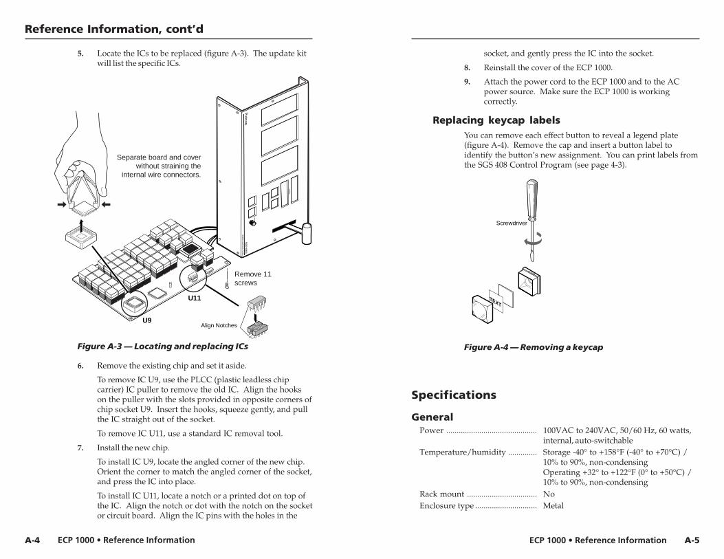
5. Locate the ICs to be replaced (figure A-3). The update kitwill list the specific ICs.
Figure A-3 — Locating and replacing ICs
6. Remove the existing chip and set it aside.
To remove IC U9, use the PLCC (plastic leadless chipcarrier) IC puller to remove the old IC. Align the hookson the puller with the slots provided in opposite corners ofchip socket U9. Insert the hooks, squeeze gently, and pullthe IC straight out of the socket.
To remove IC U11, use a standard IC removal tool.
7. Install the new chip.
To install IC U9, locate the angled corner of the new chip.Orient the corner to match the angled corner of the socket,and press the IC into place.
To install IC U11, locate a notch or a printed dot on top ofthe IC. Align the notch or dot with the notch on the socketor circuit board. Align the IC pins with the holes in the
socket, and gently press the IC into the socket.
8. Reinstall the cover of the ECP 1000.
9. Attach the power cord to the ECP 1000 and to the ACpower source. Make sure the ECP 1000 is workingcorrectly.
Replacing keycap labelsYou can remove each effect button to reveal a legend plate(figure A-4). Remove the cap and insert a button label toidentify the button’s new assignment. You can print labels fromthe SGS 408 Control Program (see page 4-3).
Figure A-4 — Removing a keycap
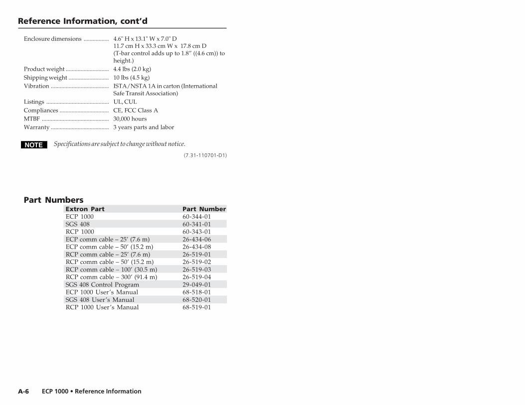
Specifications
GeneralPower ............................................ 100VAC to 240VAC, 50/60 Hz, 60 watts,
internal, auto-switchableTemperature/humidity .............. Storage -40° to +158°F (-40° to +70°C) /
10% to 90%, non-condensingOperating +32° to +122°F (0° to +50°C) /10% to 90%, non-condensing
Rack mount .................................. NoEnclosure type .............................. Metal
ECP 1000 • Reference Information
Reference Information, cont’d
A-6
Enclosure dimensions ................. 4.6" H x 13.1" W x 7.0" D11.7 cm H x 33.3 cm W x 17.8 cm D(T-bar control adds up to 1.8” ((4.6 cm)) toheight.)
Product weight ............................. 4.4 lbs (2.0 kg)Shipping weight ........................... 10 lbs (4.5 kg)Vibration ....................................... ISTA/NSTA 1A in carton (International
Safe Transit Association)Listings .......................................... UL, CULCompliances ................................. CE, FCC Class AMTBF ............................................. 30,000 hoursWarranty ....................................... 3 years parts and labor
Specifications are subject to change without notice.
(7.31-110701-D1)
Part NumbersExtron Part Part NumberECP 1000 60-344-01SGS 408 60-341-01RCP 1000 60-343-01ECP comm cable – 25’ (7.6 m) 26-434-06ECP comm cable – 50’ (15.2 m) 26-434-08RCP comm cable – 25’ (7.6 m) 26-519-01RCP comm cable – 50’ (15.2 m) 26-519-02RCP comm cable – 100’ (30.5 m) 26-519-03RCP comm cable – 300’ (91.4 m) 26-519-04SGS 408 Control Program 29-049-01ECP 1000 User’s Manual 68-518-01SGS 408 User’s Manual 68-520-01RCP 1000 User’s Manual 68-519-01
Precautions
This symbol is intended to alert the user of importantoperating and maintenance (servicing) instructionsin the literature provided with the equipment.
This symbol is intended to alert the user of thepresence of uninsulated dangerous voltage withinthe product's enclosure that may present a risk ofelectric shock.
CautionRead Instructions • Read and understand all safety and operating
instructions before using the equipment.Retain Instructions • The safety instructions should be kept for future
reference.Follow Warnings • Follow all warnings and instructions marked on the
equipment or in the user information.Avoid Attachments • Do not use tools or attachments that are not
recommended by the equipment manufacturer because they may behazardous.
WarningPower sources • This equipment should be operated only from the power source
indicated on the product. This equipment is intended to be used with a mainpower system with a grounded (neutral) conductor. The third (grounding) pin isa safety feature, do not attempt to bypass or disable it.
Power disconnection • To remove power from the equipment safely, remove allpower cords from the rear of the equipment, or the desktop power module (ifdetachable), or from the power source receptacle (wall plug).
Power cord protection • Power cords should be routed so that they are not likely tobe stepped on or pinched by items placed upon or against them.
Servicing • Refer all servicing to qualified service personnel. There are no user-serviceable parts inside. To prevent the risk of shock, do not attempt to servicethis equipment yourself because opening or removing covers may expose you todangerous voltage or other hazards.
Slots and openings • If the equipment has slots or holes in the enclosure, these areprovided to prevent overheating of sensitive components inside. These openingsmust never be blocked by other objects.
Lithium battery • There is a danger of explosion if battery is incorrectly replaced.Replace it only with the same or equivalent type recommended by themanufacturer. Dispose of used batteries according to the manufacturer'sinstructions.
Ce symbole sert à avertir l’utilisateur que ladocumentation fournie avec le matériel contient desinstructions importantes concernant l’exploitationet la maintenance (réparation).
Ce symbole sert à avertir l’utilisateur de la présencedans le boîtier de l’appareil de tensions dangereusesnon isolées posant des risques d’électrocution.
AttentionLire les instructions• Prendre connaissance de toutes les consignes de
sécurité et d’exploitation avant d’utiliser le matériel.Conserver les instructions• Ranger les consignes de sécurité afin de
pouvoir les consulter à l’avenir.Respecter les avertissements • Observer tous les avertissements et
consignes marqués sur le matériel ou présentés dans la documentationutilisateur.
Eviter les pièces de fixation • Ne pas utiliser de pièces de fixation nid’outils non recommandés par le fabricant du matériel car celarisquerait de poser certains dangers.
AvertissementAlimentations• Ne faire fonctionner ce matériel qu’avec la source d’alimentation
indiquée sur l’appareil. Ce matériel doit être utilisé avec une alimentationprincipale comportant un fil de terre (neutre). Le troisième contact (de mise à laterre) constitue un dispositif de sécurité : n’essayez pas de la contourner ni de ladésactiver.
Déconnexion de l’alimentation• Pour mettre le matériel hors tension sans danger,déconnectez tous les cordons d’alimentation de l’arrière de l’appareil ou dumodule d’alimentation de bureau (s’il est amovible) ou encore de la prise secteur.
Protection du cordon d’alimentation • Acheminer les cordons d’alimentation demanière à ce que personne ne risque de marcher dessus et à ce qu’ils ne soientpas écrasés ou pincés par des objets.
Réparation-maintenance • Faire exécuter toutes les interventions de réparation-maintenance par un technicien qualifié. Aucun des éléments internes ne peut êtreréparé par l’utilisateur. Afin d’éviter tout danger d’électrocution, l’utilisateur nedoit pas essayer de procéder lui-même à ces opérations car l’ouverture ou leretrait des couvercles risquent de l’exposer à de hautes tensions et autres dangers.
Fentes et orifices • Si le boîtier de l’appareil comporte des fentes ou des orifices,ceux-ci servent à empêcher les composants internes sensibles de surchauffer. Cesouvertures ne doivent jamais être bloquées par des objets.
Lithium Batterie • Il a danger d'explosion s'll y a remplacment incorrect de labatterie. Remplacer uniquement avec une batterie du meme type ou d'un ypeequivalent recommande par le constructeur. Mettre au reut les batteries usageesconformement aux instructions du fabricant.
Safety Instructions • English
Consignes de Sécurité • Français
Sicherheitsanleitungen • DeutschDieses Symbol soll dem Benutzer in der imLieferumfang enthaltenen Dokumentationbesonders wichtige Hinweise zur Bedienung undWartung (Instandhaltung) geben.
Dieses Symbol soll den Benutzer darauf aufmerksammachen, daß im Inneren des Gehäuses diesesProduktes gefährliche Spannungen, die nicht isoliertsind und die einen elektrischen Schock verursachenkönnen, herrschen.
AchtungLesen der Anleitungen • Bevor Sie das Gerät zum ersten Mal verwenden,
sollten Sie alle Sicherheits-und Bedienungsanleitungen genaudurchlesen und verstehen.
Aufbewahren der Anleitungen • Die Hinweise zur elektrischen Sicherheitdes Produktes sollten Sie aufbewahren, damit Sie im Bedarfsfall daraufzurückgreifen können.
Befolgen der Warnhinweise • Befolgen Sie alle Warnhinweise undAnleitungen auf dem Gerät oder in der Benutzerdokumentation.
Keine Zusatzgeräte • Verwenden Sie keine Werkzeuge oder Zusatzgeräte,die nicht ausdrücklich vom Hersteller empfohlen wurden, da diese eineGefahrenquelle darstellen können.
VorsichtStromquellen • Dieses Gerät sollte nur über die auf dem Produkt angegebene
Stromquelle betrieben werden. Dieses Gerät wurde für eine Verwendung miteiner Hauptstromleitung mit einem geerdeten (neutralen) Leiter konzipiert. Derdritte Kontakt ist für einen Erdanschluß, und stellt eine Sicherheitsfunktion dar.Diese sollte nicht umgangen oder außer Betrieb gesetzt werden.
Stromunterbrechung • Um das Gerät auf sichere Weise vom Netz zu trennen,sollten Sie alle Netzkabel aus der Rückseite des Gerätes, aus der externenStomversorgung (falls dies möglich ist) oder aus der Wandsteckdose ziehen.
Schutz des Netzkabels • Netzkabel sollten stets so verlegt werden, daß sie nichtim Weg liegen und niemand darauf treten kann oder Objekte darauf- oderunmittelbar dagegengestellt werden können.
Wartung • Alle Wartungsmaßnahmen sollten nur von qualifiziertemServicepersonal durchgeführt werden. Die internen Komponenten des Gerätessind wartungsfrei. Zur Vermeidung eines elektrischen Schocks versuchen Sie inkeinem Fall, dieses Gerät selbst öffnen, da beim Entfernen der Abdeckungen dieGefahr eines elektrischen Schlags und/oder andere Gefahren bestehen.
Schlitze und Öffnungen • Wenn das Gerät Schlitze oder Löcher im Gehäuseaufweist, dienen diese zur Vermeidung einer Überhitzung der empfindlichenTeile im Inneren. Diese Öffnungen dürfen niemals von anderen Objektenblockiert werden.
Litium-Batterie • Explosionsgefahr, falls die Batterie nicht richtig ersetzt wird.Ersetzen Sie verbrauchte Batterien nur durch den gleichen oder einenvergleichbaren Batterietyp, der auch vom Hersteller empfohlen wird. EntsorgenSie verbrauchte Batterien bitte gemäß den Herstelleranweisungen.
Este símbolo se utiliza para advertir al usuario sobreinstrucciones importantes de operación ymantenimiento (o cambio de partes) que se deseandestacar en el contenido de la documentaciónsuministrada con los equipos.
Este símbolo se utiliza para advertir al usuario sobrela presencia de elementos con voltaje peligroso sinprotección aislante, que puedan encontrarse dentrode la caja o alojamiento del producto, y que puedanrepresentar riesgo de electrocución.
PrecaucionLeer las instrucciones • Leer y analizar todas las instrucciones de
operación y seguridad, antes de usar el equipo.Conservar las instrucciones • Conservar las instrucciones de seguridad
para futura consulta.Obedecer las advertencias • Todas las advertencias e instrucciones
marcadas en el equipo o en la documentación del usuario, deben serobedecidas.
Evitar el uso de accesorios • No usar herramientas o accesorios que nosean especificamente recomendados por el fabricante, ya que podrianimplicar riesgos.
AdvertenciaAlimentación eléctrica • Este equipo debe conectarse únicamente a la fuente/tipo
de alimentación eléctrica indicada en el mismo. La alimentación eléctrica de esteequipo debe provenir de un sistema de distribución general con conductorneutro a tierra. La tercera pata (puesta a tierra) es una medida de seguridad, nopuentearia ni eliminaria.
Desconexión de alimentación eléctrica • Para desconectar con seguridad laacometida de alimentación eléctrica al equipo, desenchufar todos los cables dealimentación en el panel trasero del equipo, o desenchufar el módulo dealimentación (si fuera independiente), o desenchufar el cable del receptáculo dela pared.
Protección del cables de alimentación • Los cables de alimentación eléctrica sedeben instalar en lugares donde no sean pisados ni apretados por objetos que sepuedan apoyar sobre ellos.
Reparaciones/mantenimiento • Solicitar siempre los servicios técnicos de personalcalificado. En el interior no hay partes a las que el usuario deba acceder. Paraevitar riesgo de electrocución, no intentar personalmente la reparación/mantenimiento de este equipo, ya que al abrir o extraer las tapas puede quedarexpuesto a voltajes peligrosos u otros riesgos.
Ranuras y aberturas • Si el equipo posee ranuras o orificios en su caja/alojamiento,es para evitar el sobrecalientamiento de componentes internos sensibles. Estasaberturas nunca se deben obstruir con otros objetos.
Batería de litio • Existe riesgo de explosión si esta batería se coloca en la posiciónincorrecta. Cambiar esta batería únicamente con el mismo tipo (o su equivalente)recomendado por el fabricante. Desachar las baterías usadas siguiendo lasinstrucciones del fabricante.
Instrucciones de seguridad • Español
FCC Class A NoticeNote: This equipment has been tested and found to comply with the limits for aClass A digital device, pursuant to part 15 of the FCC Rules. These limits aredesigned to provide reasonable protection against harmful interference when theequipment is operated in a commercial environment. This equipment generates,uses and can radiate radio frequency energy and, if not installed and used inaccordance with the instruction manual, may cause harmful interference to radiocommunications. Operation of this equipment in a residential area is likely tocause harmful interference, in which case the user will be required to correct theinterference at his own expense.
Note: This unit was tested with shielded cables on the peripheral devices.Shielded cables must be used with the unit to ensure compliance.
Extron’s WarrantyExtron Electronics warrants this product against defects in materials andworkmanship for a period of three years from the date of purchase. In the event ofmalfunction during the warranty period attributable directly to faultyworkmanship and/or materials, Extron Electronics will, at its option, repair orreplace said products or components, to whatever extent it shall deem necessary torestore said product to proper operating condition, provided that it is returnedwithin the warranty period, with proof of purchase and description of malfunctionto:
USA, Canada, South America, Europe, Africa, and the Middle East:and Central America:
Extron Electronics, EuropeExtron Electronics Beeldschermweg 6C1230 South Lewis Street 3821 AH AmersfoortAnaheim, CA 92805, USA The Netherlands
Asia: Japan:Extron Electronics, Japan
Extron Electronics, Asia Daisan DMJ Bldg. 6F,135 Joo Seng Road, #04-01 3-9-1 Kudan MinamiPM Industrial Bldg. Chiyoda-ku, Tokyo 102-0074Singapore 368363 Japan
This Limited Warranty does not apply if the fault has been caused by misuse,improper handling care, electrical or mechanical abuse, abnormal operatingconditions or non-Extron authorized modification to the product.
If it has been determined that the product is defective, please call Extron and ask foran Applications Engineer at (714) 491-1500 (USA), 31.33.453.4040 (Europe), or65.6383.4400 (Asia) to receive an RA# (Return Authorization number). This willbegin the repair process as quickly as possible.
Units must be returned insured, with shipping charges prepaid. If not insured,you assume the risk of loss or damage during shipment. Returned units mustinclude the serial number and a description of the problem, as well as the name ofthe person to contact in case there are any questions.
Extron Electronics makes no further warranties either expressed or implied withrespect to the product and its quality, performance, merchantability, or fitness forany particular use. In no event will Extron Electronics be liable for direct, indirect,or consequential damages resulting from any defect in this product even if ExtronElectronics has been advised of such damage.
Please note that laws vary from state to state and country to country, and thatsome provisions of this warranty may not apply to you.