Embed Size (px)
Citation preview
© 2010 Extron Electronics. All rights reserved.
Extron USA - West Headquarters
+800.633.9876Inside USA / Canada Only
+1.714.491.1500+1.714.491.1517 FAX
Extron USA - East
+800.633.9876Inside USA / Canada Only
+1.919.863.1794+1.919.863.1797 FAX
Extron Europe
+800.3987.6673Inside Europe Only
+31.33.453.4040+31.33.453.4050 FAX
Extron Asia
+800.7339.8766Inside Asia Only
+65.6383.4400+65.6383.4664 FAX
Extron Japan
+81.3.3511.7655+81.3.3511.7656 FAX
Extron China
+400.883.1568Inside China Only
+86.21.3760.1568+86.21.3760.1566 FAX
Extron Middle East
+971.4.2991800+971.4.2991880 FAX
Setup Guide
68-1560-01 Rev. B03 10
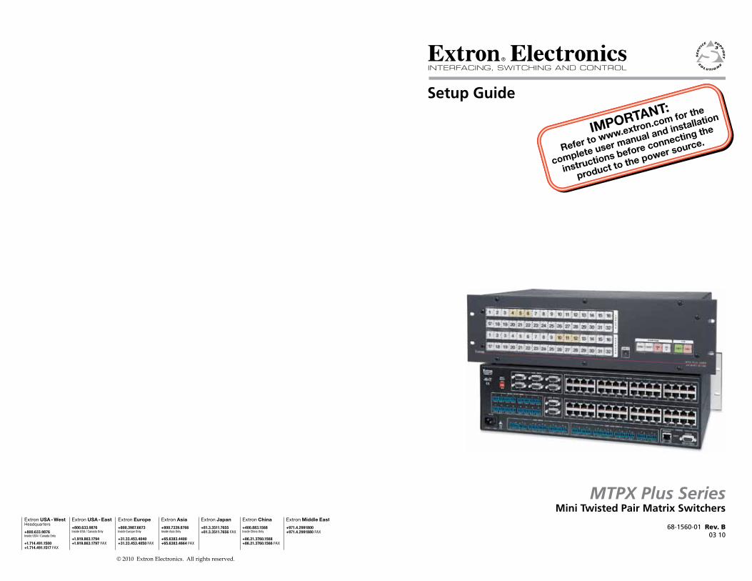
MTPX Plus SeriesMini Twisted Pair Matrix Switchers
Precautions
This symbol is intended to alert the user of important operating and maintenance (servicing) instructions in the literature provided with the equipment.
This symbol is intended to alert the user of the presence of uninsulated dangerous voltage within the product’s enclosure that may present a risk of electric shock.
CautionRead Instructions • Read and understand all safety and operating
instructions before using the equipment. Retain Instructions • The safety instructions should be kept for future
reference.Follow Warnings • Follow all warnings and instructions marked on the
equipment or in the user information.Avoid Attachments • Do not use tools or attachments that are not
recommended by the equipment manufacturer because they may be hazardous.
WarningPower sources • This equipment should be operated only from the power source
indicated on the product. This equipment is intended to be used with a main power system with a grounded (neutral) conductor. The third (grounding) pin is a safety feature, do not attempt to bypass or disable it.
Power disconnection • To remove power from the equipment safely, remove all power cords from the rear of the equipment, or the desktop power module (if detachable), or from the power source receptacle (wall plug).
Power cord protection • Power cords should be routed so that they are not likely to be stepped on or pinched by items placed upon or against them.
Servicing • Refer all servicing to qualified service personnel. There are no user-serviceable parts inside. To prevent the risk of shock, do not attempt to service this equipment yourself because opening or removing covers may expose you to dangerous voltage or other hazards.
Slots and openings • If the equipment has slots or holes in the enclosure, these are provided to prevent overheating of sensitive components inside. These openings must never be blocked by other objects.
Lithium battery • There is a danger of explosion if battery is incorrectly replaced. Replace it only with the same or equivalent type recommended by the manufacturer. Dispose of used batteries according to the manufacturer’s instructions.
Ce symbole sert à avertir l’utilisateur que la documentation fournie avec le matériel contient des instructions importantes concernant l’exploitation et la maintenance (réparation).
Ce symbole sert à avertir l’utilisateur de la présence dans le boîtier de l’appareil de tensions dangereuses non isolées posant des risques d’électrocution.
AttentionLire les instructions• Prendre connaissance de toutes les consignes de
sécurité et d’exploitation avant d’utiliser le matériel.Conserver les instructions• Ranger les consignes de sécurité afin de pouvoir
les consulter à l’avenir.Respecter les avertissements • Observer tous les avertissements et consignes
marqués sur le matériel ou présentés dans la documentation utilisateur.Eviter les pièces de fixation • Ne pas utiliser de pièces de fixation ni d’outils
non recommandés par le fabricant du matériel car cela risquerait de poser certains dangers.
AvertissementAlimentations• Ne faire fonctionner ce matériel qu’avec la source d’alimentation
indiquée sur l’appareil. Ce matériel doit être utilisé avec une alimentation principale comportant un fil de terre (neutre). Le troisième contact (de mise à la terre) constitue un dispositif de sécurité : n’essayez pas de la contourner ni de la désactiver.
Déconnexion de l’alimentation• Pour mettre le matériel hors tension sans danger, déconnectez tous les cordons d’alimentation de l’arrière de l’appareil ou du module d’alimentation de bureau (s’il est amovible) ou encore de la prise secteur.
Protection du cordon d’alimentation • Acheminer les cordons d’alimentation de manière à ce que personne ne risque de marcher dessus et à ce qu’ils ne soient pas écrasés ou pincés par des objets.
Réparation-maintenance • Faire exécuter toutes les interventions de réparation-maintenance par un technicien qualifié. Aucun des éléments internes ne peut être réparé par l’utilisateur. Afin d’éviter tout danger d’électrocution, l’utilisateur ne doit pas essayer de procéder lui-même à ces opérations car l’ouverture ou le retrait des couvercles risquent de l’exposer à de hautes tensions et autres dangers.
Fentes et orifices • Si le boîtier de l’appareil comporte des fentes ou des orifices, ceux-ci servent à empêcher les composants internes sensibles de surchauffer. Ces ouvertures ne doivent jamais être bloquées par des objets.
Lithium Batterie • Il a danger d’explosion s’ll y a remplacment incorrect de la batterie. Remplacer uniquement avec une batterie du meme type ou d’un ype equivalent recommande par le constructeur. Mettre au reut les batteries usagees conformement aux instructions du fabricant.
Safety Instructions • English
Consignes de Sécurité • Français
Sicherheitsanleitungen • DeutschDieses Symbol soll dem Benutzer in der im Lieferumfang enthaltenen Dokumentation besonders wichtige Hinweise zur Bedienung und Wartung (Instandhaltung) geben.
Dieses Symbol soll den Benutzer darauf aufmerksam machen, daß im Inneren des Gehäuses dieses Produktes gefährliche Spannungen, die nicht isoliert sind und die einen elektrischen Schock verursachen können, herrschen.
AchtungLesen der Anleitungen • Bevor Sie das Gerät zum ersten Mal verwenden,
sollten Sie alle Sicherheits-und Bedienungsanleitungen genau durchlesen und verstehen.
Aufbewahren der Anleitungen • Die Hinweise zur elektrischen Sicherheit des Produktes sollten Sie aufbewahren, damit Sie im Bedarfsfall darauf zurückgreifen können.
Befolgen der Warnhinweise • Befolgen Sie alle Warnhinweise und Anleitungen auf dem Gerät oder in der Benutzerdokumentation.
Keine Zusatzgeräte • Verwenden Sie keine Werkzeuge oder Zusatzgeräte, die nicht ausdrücklich vom Hersteller empfohlen wurden, da diese eine Gefahrenquelle darstellen können.
VorsichtStromquellen • Dieses Gerät sollte nur über die auf dem Produkt angegebene
Stromquelle betrieben werden. Dieses Gerät wurde für eine Verwendung mit einer Hauptstromleitung mit einem geerdeten (neutralen) Leiter konzipiert. Der dritte Kontakt ist für einen Erdanschluß, und stellt eine Sicherheitsfunktion dar. Diese sollte nicht umgangen oder außer Betrieb gesetzt werden.
Stromunterbrechung • Um das Gerät auf sichere Weise vom Netz zu trennen, sollten Sie alle Netzkabel aus der Rückseite des Gerätes, aus der externen Stomversorgung (falls dies möglich ist) oder aus der Wandsteckdose ziehen.
Schutz des Netzkabels • Netzkabel sollten stets so verlegt werden, daß sie nicht im Weg liegen und niemand darauf treten kann oder Objekte darauf- oder unmittelbar dagegengestellt werden können.
Wartung • Alle Wartungsmaßnahmen sollten nur von qualifiziertem Servicepersonal durchgeführt werden. Die internen Komponenten des Gerätes sind wartungsfrei. Zur Vermeidung eines elektrischen Schocks versuchen Sie in keinem Fall, dieses Gerät selbst öffnen, da beim Entfernen der Abdeckungen die Gefahr eines elektrischen Schlags und/oder andere Gefahren bestehen.
Schlitze und Öffnungen • Wenn das Gerät Schlitze oder Löcher im Gehäuse aufweist, dienen diese zur Vermeidung einer Überhitzung der empfindlichen Teile im Inneren. Diese Öffnungen dürfen niemals von anderen Objekten blockiert werden.
Litium-Batterie • Explosionsgefahr, falls die Batterie nicht richtig ersetzt wird. Ersetzen Sie verbrauchte Batterien nur durch den gleichen oder einen vergleichbaren Batterietyp, der auch vom Hersteller empfohlen wird. Entsorgen Sie verbrauchte Batterien bitte gemäß den Herstelleranweisungen.
Este símbolo se utiliza para advertir al usuario sobre instrucciones importantes de operación y mantenimiento (o cambio de partes) que se desean destacar en el contenido de la documentación suministrada con los equipos.
Este símbolo se utiliza para advertir al usuario sobre la presencia de elementos con voltaje peligroso sin protección aislante, que puedan encontrarse dentro de la caja o alojamiento del producto, y que puedan representar riesgo de electrocución.
PrecaucionLeer las instrucciones • Leer y analizar todas las instrucciones de operación y
seguridad, antes de usar el equipo.Conservar las instrucciones • Conservar las instrucciones de seguridad para
futura consulta.Obedecer las advertencias • Todas las advertencias e instrucciones marcadas
en el equipo o en la documentación del usuario, deben ser obedecidas.Evitar el uso de accesorios • No usar herramientas o accesorios que no
sean especificamente recomendados por el fabricante, ya que podrian implicar riesgos.
AdvertenciaAlimentación eléctrica • Este equipo debe conectarse únicamente a la fuente/tipo
de alimentación eléctrica indicada en el mismo. La alimentación eléctrica de este equipo debe provenir de un sistema de distribución general con conductor neutro a tierra. La tercera pata (puesta a tierra) es una medida de seguridad, no puentearia ni eliminaria.
Desconexión de alimentación eléctrica • Para desconectar con seguridad la acometida de alimentación eléctrica al equipo, desenchufar todos los cables de alimentación en el panel trasero del equipo, o desenchufar el módulo de alimentación (si fuera independiente), o desenchufar el cable del receptáculo de la pared.
Protección del cables de alimentación • Los cables de alimentación eléctrica se deben instalar en lugares donde no sean pisados ni apretados por objetos que se puedan apoyar sobre ellos.
Reparaciones/mantenimiento • Solicitar siempre los servicios técnicos de personal calificado. En el interior no hay partes a las que el usuario deba acceder. Para evitar riesgo de electrocución, no intentar personalmente la reparación/mantenimiento de este equipo, ya que al abrir o extraer las tapas puede quedar expuesto a voltajes peligrosos u otros riesgos.
Ranuras y aberturas • Si el equipo posee ranuras o orificios en su caja/alojamiento, es para evitar el sobrecalientamiento de componentes internos sensibles. Estas aberturas nunca se deben obstruir con otros objetos.
Batería de litio • Existe riesgo de explosión si esta batería se coloca en la posición incorrecta. Cambiar esta batería únicamente con el mismo tipo (o su equivalente) recomendado por el fabricante. Desachar las baterías usadas siguiendo las instrucciones del fabricante.
Instrucciones de seguridad • Español
Extron WarrantyExtron Electronics warrants this product against defects in materials and workmanship for a period of three years from the date of purchase. In the event of malfunction during the warranty period attributable directly to faulty workmanship and/or materials, Extron Electronics will, at its option, repair or replace said products or components, to whatever extent it shall deem necessary to restore said product to proper operating condition, provided that it is returned within the warranty period, with proof of purchase and description of malfunction to:
USA, Canada, South America, Europe, Africa, and the Middle East: and Central America: Extron Electronics, Europe Extron Electronics Beeldschermweg 6C 1001 East Ball Road 3821 AH Amersfoort Anaheim, CA 92805, USA The Netherlands
Asia: Japan: Extron Electronics, Asia Extron Electronics, Japan 135 Joo Seng Road, #04-01 Kyodo Building PM Industrial Bldg. 16 Ichibancho Singapore 368363 Chiyoda-ku, Tokyo 102-0082 Japan
This Limited Warranty does not apply if the fault has been caused by misuse, improper handling care, electrical or mechanical abuse, abnormal operating conditions or non-Extron authorized modification to the product.
If it has been determined that the product is defective, please call Extron and ask for an Applications Engineer at (714) 491-1500 (USA), 31.33.453.4040 (Europe), 65.6383.4400 (Asia), or 81.3.3511.7655 (Japan) to receive an RA# (Return Authorization number). This will begin the repair process as quickly as possible.
Units must be returned insured, with shipping charges prepaid. If not insured, you assume the risk of loss or damage during shipment. Returned units must include the serial number and a description of the problem, as well as the name of the person to contact in case there are any questions.
Extron Electronics makes no further warranties either expressed or implied with respect to the product and its quality, performance, merchantability, or fitness for any particular use. In no event will Extron Electronics be liable for direct, indirect, or consequential damages resulting from any defect in this product even if Extron Electronics has been advised of such damage.
Please note that laws vary from state to state and country to country, and that some provisions of this warranty may not apply to you.

安全须知 • 中文这个符号提示用户该设备用户手册中
有重要的操作和维护说明。
这个符号警告用户该设备机壳内有暴
露的危险电压,有触电危险。
注意阅读说明书 • 用户使用该设备前必须阅读并理
解所有安全和使用说明。
保存说明书 • 用户应保存安全说明书以备将来使
用。
遵守警告 • 用户应遵守产品和用户指南上的所有安
全和操作说明。
避免追加 • 不要使用该产品厂商没有推荐的工具或
追加设备,以避免危险。
警告电源 • 该设备只能使用产品上标明的电源。 设备
必须使用有地线的供电系统供电。 第三条线
(地线)是安全设施,不能不用或跳过。
拔掉电源 • 为安全地从设备拔掉电源,请拔掉所有设备后
或桌面电源的电源线,或任何接到市电系统的电源线。
电源线保护 • 妥善布线, 避免被踩踏,或重物挤压。
维护 • 所有维修必须由认证的维修人员进行。 设备内部
没有用户可以更换的零件。为避免出现触电危险不要自
己试图打开设备盖子维修该设备。
通风孔 • 有些设备机壳上有通风槽或孔,它们是用来防止
机内敏感元件过热。 不要用任何东西挡住通风孔。
锂电池 • 不正确的更换电池会有爆炸的危险。 必须使用
与厂家推荐的相同或相近型号的电池。 按照生产厂的
建议处理废弃电池。
FCC Class A NoticeThis equipment has been tested and found to comply with the limits for a Class A digital device, pursuant to part 15 of the FCC Rules. Front Panel Operation is subject to the following two conditions: (1) this device may not cause harmful interference, and (2) this device must accept any interference received, including interference that may cause undesired operation. The Class A limits are designed to provide reasonable protection against harmful interference when the equipment is operated in a commercial environment. This equipment generates, uses, and can radiate radio frequency energy and, if not installed and used in accordance with the instruction manual, may cause harmful interference to radio communications. Front Panel Operation of this equipment in a residential area is likely to cause harmful interference, in which case the user will be required to correct the interference at his own expense.
N Thisunitwastestedwithshieldedcablesontheperipheraldevices.ShieldedcablesmustbeusedwiththeunittoensurecompliancewithFCCemissionslimits.
Refer also to the MTPX Plus User’s Manual at www.extron.com.
Table of Contents
Chapter One • Introduction .................................................... 1-1
About this Manual�..................................................................... 1-2
About the MTPX Pl�us Switchers............................................ 1-2
Twisted Pair (TP) Cabl�e Transmission Distance................. 1-4
TP Skew Equal�ization................................................................ 1-5
Chapter Two • Installation....................................................... 2-1
Rear Panel�..................................................................................... 2-2Inputs....................................................................................... 2-3RS-232 output inserts............................................................. 2-4Outputs.................................................................................... 2-4Remote control�........................................................................ 2-5Power....................................................................................... 2-6
Front Panel�.................................................................................... 2-6
Chapter Three • Front Panel Operation.......................... 3-1
Creating a Tie............................................................................... 3-2
Saving or Recal�l�ing a Preset.................................................... 3-3
Setting the Front Panel� Locks (Executive Modes)............ 3-4Sel�ecting Lock mode 2 or toggl�ing between mode 2 and mode 0�................................................................ 3-4Sel�ecting Lock mode 2 or toggl�ing between mode 2 and mode 1�................................................................ 3-5
Defining the Audio/RS-232 Wire Pair and Configuring the Remote Port..........................................3-6
Viewing and Adjusting the Audio Level�............................. 3-7
Viewing Ties and Muting Outputs....................................... 3-8
Video Adjustments..................................................................... 3-8
Chapter Four • Remote Control and Optimizing the Video................................................................... 4-1
Sel�ected SIS™ Commands......................................................... 4-2Establ�ishing a network (Ethernet) connection..................... 4-2
Connection timeouts...............................................................4-2Number of connections...........................................................4-3Verbose mode..........................................................................4-3
Establ�ishing a USB port connection....................................... 4-3Host-to-switcher instructions................................................. 4-3Command/response tabl�e for sel�ected SIS commands........ 4-4
iMTPX Pl�us Series • Tabl�e of Contents
Refer also to the MTPX Plus User’s Manual at www.extron.com.
1Chapter One
Introduction
About.this.Manual
About.the.MTPX.Plus.Switchers
Twisted.Pair.(TP).Cable.Transmission.Distance
TP.Skew.Equalization
Instal�l�ing and Starting the Control� Program................... 4-15Instal�l�ing the program.......................................................... 4-15First-time connection considerations.................................. 4-16
LAN port connection.............................................................4-16USB port connection.............................................................4-16
Starting the program............................................................ 4-17Optimizing the video............................................................ 4-18
Setting the MTP transmitter Pre-Peak feature....................4-19Setting MTPX l�evel� and peaking using the MTP signal� generator...............................................................................4-19Manual�l�y setting the MTPX l�evel� and peaking...................4-20Setting MTPX skew...............................................................4-20Sel�ecting MTPX Pl�us Pre-Peak...............................................4-22Setting MTP Receiver l�evel�/peaking....................................4-22
Accessing the HTML Pages.................................................... 4-23Configuring for Network Communication.......................... 4-24Loading the start-up page.................................................... 4-25
Alltrademarksmentionedinthismanualarethepropertiesoftheirrespectiveowners.
ii MTPX Pl�us Series • Tabl�e of Contents
Table of Contents, cont’d
MTPX Pl�us Series Matrix Switcher
1-2Refer also to the MTPX Plus User’s Manual at www.extron.com.
1-3Refer also to the MTPX Plus User’s Manual at www.extron.com.
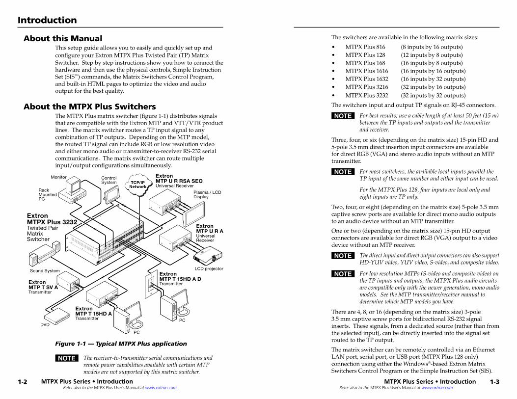
The switchers are available in the following matrix sizes:
• MTPX Plus 816 (8 inputs by 16 outputs)• MTPX Plus 128 (12 inputs by 8 outputs)• MTPX Plus 168 (16 inputs by 8 outputs)• MTPX Plus 1616 (16 inputs by 16 outputs)• MTPX Plus 1632 (16 inputs by 32 outputs)• MTPX Plus 3216 (32 inputs by 16 outputs)• MTPX Plus 3232 (32 inputs by 32 outputs)
The switchers input and output TP signals on RJ-45 connectors.
N Forbestresults,useacablelengthofatleast50feet(15m)betweentheTPinputsandoutputsandthetransmitterandreceiver.
Three, four, or six (depending on the matrix size) 15-pin HD and 5-pole 3.5 mm direct insertion input connectors are available for direct RGB (VGA) and stereo audio inputs without an MTP transmitter.
N Formostswitchers,theavailablelocalinputsparalleltheTPinputofthesamenumberandeitherinputcanbeused.
FortheMTPXPlus128,fourinputsarelocalonlyandeightinputsareTPonly.
Two, four, or eight (depending on the matrix size) 5-pole 3.5 mm captive screw ports are available for direct mono audio outputs to an audio device without an MTP transmitter.
One or two (depending on the matrix size) 15-pin HD output connectors are available for direct RGB (VGA) output to a video device without an MTP receiver.
N ThedirectinputanddirectoutputconnectorscanalsosupportHD-YUVvideo,YUVvideo,S-video,andcompositevideo.
N ForlowresolutionMTPs(S-videoandcompositevideo)ontheTPinputsandoutputs,theMTPXPlusaudiocircuitsarecompatibleonlywiththenewergeneration,monoaudiomodels.SeetheMTPtransmitter/receivermanualtodeterminewhichMTPmodelsyouhave.
There are 4, 8, or 16 (depending on the matrix size) 3-pole 3.5 mm captive screw ports for bidirectional RS-232 signal inserts. These signals, from a dedicated source (rather than from the selected input), can be directly inserted into the signal set routed to the TP output.
The matrix switcher can be remotely controlled via an Ethernet LAN port, serial port, or USB port (MTPX Plus 128 only) connection using either the Windows®-based Extron Matrix Switchers Control Program or the Simple Instruction Set (SIS).
About this ManualThis setup guide allows you to easily and quickly set up and configure your Extron MTPX Plus Twisted Pair (TP) Matrix Switcher. Step by step instructions show you how to connect the hardware and then use the physical controls, Simple Instruction Set (SIS™) commands, the Matrix Switchers Control Program, and built-in HTML pages to optimize the video and audio output for the best quality.
About the MTPX Plus SwitchersThe MTPX Plus matrix switcher (figure 1-1) distributes signals that are compatible with the Extron MTP and VTT/VTR product lines. The matrix switcher routes a TP input signal to any combination of TP outputs. Depending on the MTP model, the routed TP signal can include RGB or low resolution video and either mono audio or transmitter-to-receiver RS-232 serial communications. The matrix switcher can route multiple input/output configurations simultaneously.
ETHERNET
ACT
INPUT
SELECT
LOCAL
RJ-45
LOCAL INPUTS
1
2
3
4
5
6
7
8
9
10
11
12
13
14
15
16
17
18
19
20
21
22
23
24
25
26
27
28
29
30
31
32
1
2
3
4
5
6
7
8
9
10
11
12
13
14
15
16
17
18
19
20
21
22
23
24
25
26
27
28
29
30
31
32
1
2
2
1
3
4
5
6
RS-232 OUTPUT INSERTION
LOCAL OUTPUTS
OUTPUTS
INPUTS
CONTROL
MONO AUDIO OUTPUTS
AUDIO INPUTS
LINK
RESET
L
R1
L
R2
L
R3
L
R4
L
R5
L
R6
L
R1
L
R2
L
R3
L
R4
L
R5
L
R6
L
R7
L
R8
Tx Rx
1
Tx Rx
2
Tx Rx
3
Tx Rx
4
Tx Rx
5
Tx Rx
6
Tx Rx
7
Tx Rx
8
Tx Rx
9
Tx Rx
10
Tx Rx
11
Tx Rx
12
Tx Rx
13
Tx Rx
14
Tx Rx
15
Tx Rx
16US
LISTED
1T23
I.T.E.
®
L
RINPUT
MTP T SV A
S-VIDEOOUTPUT
12V
0.5a MAX
DVD-RW/-R RECORDING
Precision Cinema Progressive
INPUT
RGB
POWER
12V
0.5A MAX
1MONO AUDIO2
VID
Y/C
B-Y
Y
R-Y
OUTPUTS
RS-232
Tx RxSPACE
INPUT
RGB
POWER
12V
0.5A MAX
VID
Y/C
OUTPUTS
MTP U R
A
1MONO AUDIO2
COMPUTER IN
AUDIO IN
INPUT
AUDIO
MONITOR
POWER
12V
.5A MAX
OUTPUT
MTP T 15HD A
PRE-PEAK
ON
OFF
TCP/IPNetwork
ExtronMTPX Plus 3232Twisted PairMatrix Switcher
ControlSystem
ExtronMTP T SV ATransmitter
DVD
Sound System
ExtronMTP U R RSA SEQUniversal Receiver
ExtronMTP U R AUniversal Receiver
Plasma / LCDDisplay
ExtronMTP T 15HD A DTransmitter
PC
ExtronMTP T 15HD ATransmitter
Rack Mounted PC
PC
LCD projector
Monitor
Figure 1-1 — Typical MTPX Plus application
N Thereceiver-to-transmitterserialcommunicationsandremotepowercapabilitiesavailablewithcertainMTPmodelsarenotsupportedbythismatrixswitcher.
MTPX Pl�us Series • Introduction
Introduction
MTPX Pl�us Series • Introduction
Refer also to the MTPX Plus User’s Manual at www.extron.com.
Refer also to the MTPX Plus User’s Manual at www.extron.com.
Twisted Pair (TP) Cable Transmission DistanceC Donotconnectthisdevicetoacomputerdataor
telecommunicationsnetwork.
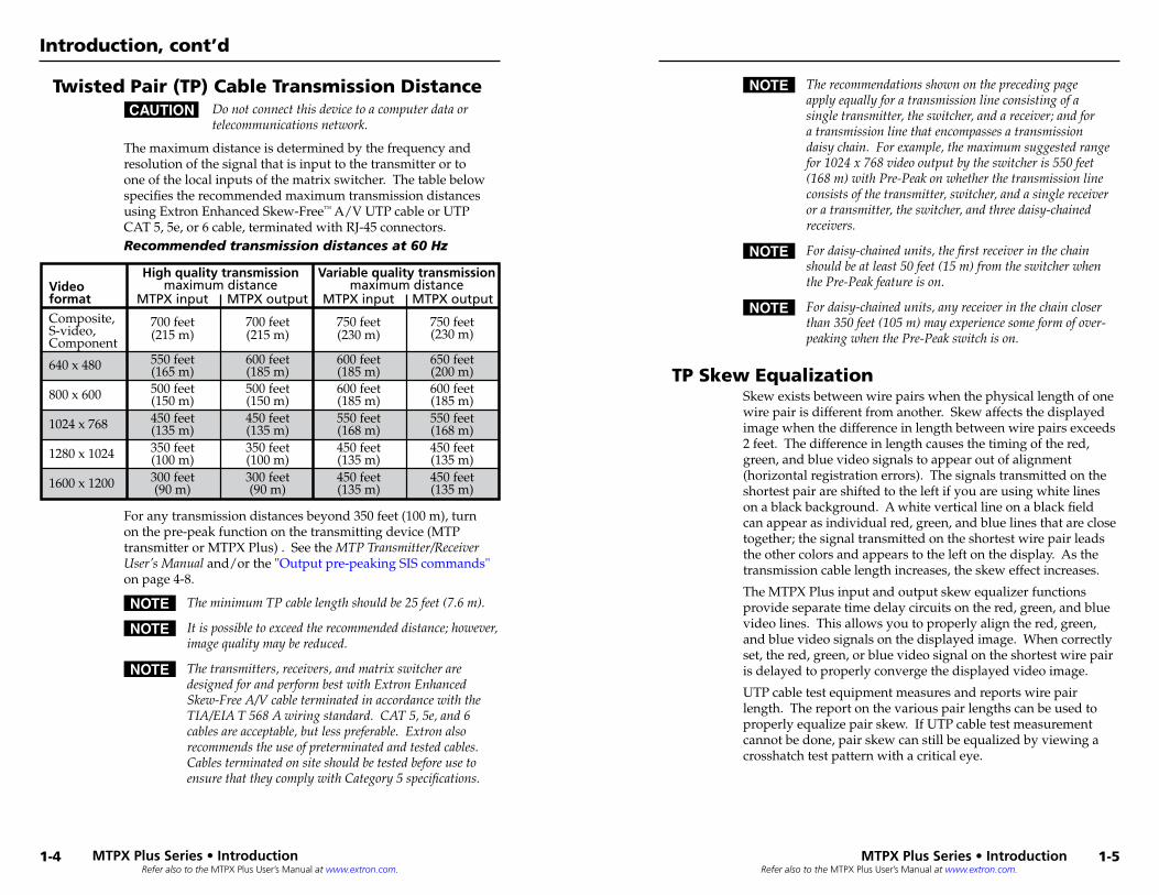
The maximum distance is determined by the frequency and resolution of the signal that is input to the transmitter or to one of the local inputs of the matrix switcher. The table below specifies the recommended maximum transmission distances using Extron Enhanced Skew-Free™ A/V UTP cable or UTP CAT 5, 5e, or 6 cable, terminated with RJ-45 connectors.Recommended transmission distances at 60 Hz
Composite, S-video, Component
640 x 480
800 x 600
1024 x 768
1280 x 1024
1600 x 1200
Video format
700 feet(215 m)
550 feet(165 m)500 feet(150 m)
600 feet(185 m)
450 feet(135 m)
550 feet(168 m)
350 feet(100 m)
450 feet(135 m)
300 feet(90 m)
450 feet(135 m)
MTPX input
High quality transmissionmaximum distance
MTPX output
750 feet(230 m)
750 feet(230 m)
600 feet(185 m)
650 feet(200 m)600 feet(185 m)550 feet(168 m)450 feet(135 m)450 feet(135 m)
MTPX input
700 feet(215 m)
600 feet(185 m)500 feet(150 m)450 feet(135 m)350 feet(100 m)300 feet(90 m)
MTPX output
Variable quality transmissionmaximum distance
For any transmission distances beyond 350 feet (100 m), turn on the pre-peak function on the transmitting device (MTP transmitter or MTPX Plus) . See the MTPTransmitter/ReceiverUser’sManual and/or the "Output pre-peaking SIS commands" on page 4-8.
N TheminimumTPcablelengthshouldbe25feet(7.6m).
N Itispossibletoexceedtherecommendeddistance;however,imagequalitymaybereduced.
N Thetransmitters,receivers,andmatrixswitcheraredesignedforandperformbestwithExtronEnhancedSkew-FreeA/VcableterminatedinaccordancewiththeTIA/EIAT568Awiringstandard.CAT5,5e,and6cablesareacceptable,butlesspreferable.Extronalsorecommendstheuseofpreterminatedandtestedcables.CablesterminatedonsiteshouldbetestedbeforeusetoensurethattheycomplywithCategory5specifications.
N Therecommendationsshownontheprecedingpageapplyequallyforatransmissionlineconsistingofasingletransmitter,theswitcher,andareceiver;andforatransmissionlinethatencompassesatransmissiondaisychain.Forexample,themaximumsuggestedrangefor1024x768videooutputbytheswitcheris550feet(168m)withPre-Peakonwhetherthetransmissionlineconsistsofthetransmitter,switcher,andasinglereceiveroratransmitter,theswitcher,andthreedaisy-chainedreceivers.
N Fordaisy-chainedunits,thefirstreceiverinthechainshouldbeatleast50feet(15m)fromtheswitcherwhenthePre-Peakfeatureison.
N Fordaisy-chainedunits,anyreceiverinthechaincloserthan350feet(105m)mayexperiencesomeformofover-peakingwhenthePre-Peakswitchison.
TP Skew EqualizationSkew exists between wire pairs when the physical length of one wire pair is different from another. Skew affects the displayed image when the difference in length between wire pairs exceeds 2 feet. The difference in length causes the timing of the red, green, and blue video signals to appear out of alignment (horizontal registration errors). The signals transmitted on the shortest pair are shifted to the left if you are using white lines on a black background. A white vertical line on a black field can appear as individual red, green, and blue lines that are close together; the signal transmitted on the shortest wire pair leads the other colors and appears to the left on the display. As the transmission cable length increases, the skew effect increases.
The MTPX Plus input and output skew equalizer functions provide separate time delay circuits on the red, green, and blue video lines. This allows you to properly align the red, green, and blue video signals on the displayed image. When correctly set, the red, green, or blue video signal on the shortest wire pair is delayed to properly converge the displayed video image.
UTP cable test equipment measures and reports wire pair length. The report on the various pair lengths can be used to properly equalize pair skew. If UTP cable test measurement cannot be done, pair skew can still be equalized by viewing a crosshatch test pattern with a critical eye.
MTPX Pl�us Series • Introduction
Introduction, cont’d
1-4 MTPX Pl�us Series • Introduction
1-5
Refer also to the MTPX Plus User’s Manual at www.extron.com.
2Chapter Two
Installation
Rear.Panel.
Front.Panel
MTPX Pl�us Series • Introduction
Introduction, cont’d
1-6
MTPX Pl�us Series Matrix Switcher
2-2Refer also to the MTPX Plus User’s Manual at www.extron.com.
Refer also to the MTPX Plus User’s Manual at www.extron.com.
Rear Panel
MONO AUDIO OUTPUTS
OUTPUTS
RGB
RGB
1
2 3
1
Tx Rx
1L R
1 2AUDIO
3
2L R
3L R
4L R
LOCAL INPUTS LOCAL OUTPUT
RGB
RGB
INPUT SELECT
ON
LOCAL
RJ - 45
1 2 3
RS
-232
/RS
-422
RE
MO
TE
CONTROLRS - 232 OUTPUT INSERT
Tx Rx Tx Rx Tx Rx Tx Rx Tx Rx Tx Rx Tx Rx
INPUTS1 2 3 4 5 6 7 8
9 10 11 12 13 14 15 16
1 2 3 4 5 6 7 8
9 10 11 12 13 14 15 16
1 2 3 4 5 6 7 8
LA
N
RE
SE
T
12 9
2 5
6
1
11
OUTPUTSINPUTS
7 4
83
AUDIO
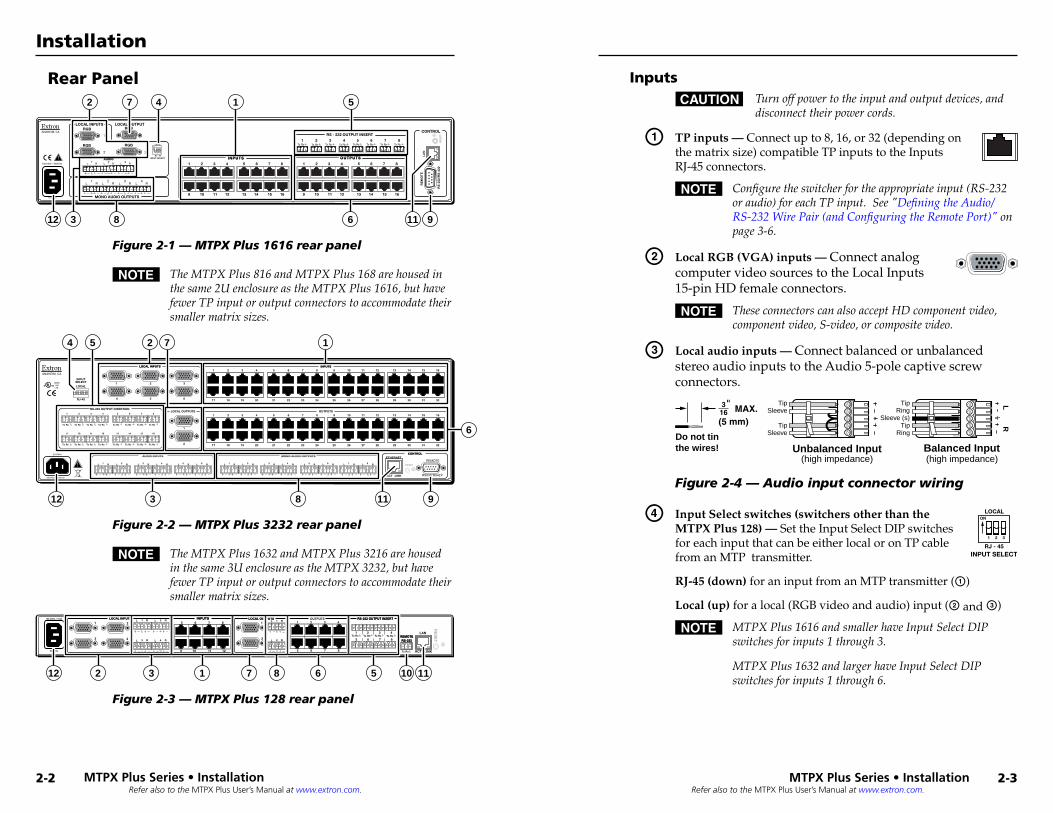
Figure 2-1 — MTPX Plus 1616 rear panel
N TheMTPXPlus816andMTPXPlus168arehousedinthesame2UenclosureastheMTPXPlus1616,buthavefewerTPinputoroutputconnectorstoaccommodatetheirsmallermatrixsizes.
ETHERNET
ACT
INPUTSELECTLOCAL
RJ-45
LOCAL INPUTS1 2 3 4 5 6 7 8 9 10 11 12 13 14 15 16
17 18 19 20 21 22 23 24 25 26 27 28 29 30 31 32
1 2 3 4 5 6 7 8 9 10 11 12 13 14 15 16
17 18 19 20 21 22 23 24 25 26 27 28 29 30 31 32
1
2
21 3
4 5 6
RS-232 OUTPUT INSERTIONLOCAL OUTPUTS OUTPUTS
INPUTS
CONTROLCONTROLMONO AUDIO OUTPUTSAUDIO INPUTS
LINK
RESETL R1 L R2 L R3 L R4 L R5 L R6 L R1 L R2 L R3 L R4 L R5 L R6 L R7 L R8
Tx Rx
1
Tx Rx
2
Tx Rx
3
Tx Rx
4
Tx Rx
5
Tx Rx
6
Tx Rx
7
Tx Rx
8
Tx Rx
9
Tx Rx
10
Tx Rx
11
Tx Rx
12
Tx Rx
13
Tx Rx
14
Tx Rx
15
Tx Rx
16
USLISTED
1T23I.T.E.
®
6
12 911
4
83
125 7
LOCAL INPUTS INPUTS
Figure 2-2 — MTPX Plus 3232 rear panel
N TheMTPXPlus1632andMTPXPlus3216arehousedinthesame3UenclosureastheMTPX3232,buthavefewerTPinputoroutputconnectorstoaccommodatetheirsmallermatrixsizes.
100-240V 0.8A
50-60Hz
OUTPUTS1 2
3 4
LOCAL INPUTS INPUTS1 2 3 4
RE
SE
T
LAN
ACT LINK
1
2
L R2L R1
L R4L R3
5 6 7 8
1 2 3 4
5 6 7 8
Tx Rx
L R2
L R15 6 7 8
9 10 11 12
LOCAL OUTPUTS RS-232 OUTPUT INSERT
REMOTERS-232
Tx Rx Tx Rx Tx Rx Tx Rx
LOCAL OUTPUTSLOCAL INPUTS
12 10 112 3 7 561 8
INPUTS RS-232 OUTPUT INSERT
REMOTERS-232
Figure 2-3 — MTPX Plus 128 rear panel
InputsC Turnoffpowertotheinputandoutputdevices,and
disconnecttheirpowercords.
a TP inputs — Connect up to 8, 16, or 32 (depending on the matrix size) compatible TP inputs to the Inputs RJ-45 connectors.
N Configuretheswitcherfortheappropriateinput(RS-232oraudio)foreachTPinput.See"DefiningtheAudio/RS-232WirePair(andConfiguringtheRemotePort)"onpage3-6.
b Local RGB (VGA) inputs — Connect analog computer video sources to the Local Inputs 15-pin HD female connectors.
N TheseconnectorscanalsoacceptHDcomponentvideo,componentvideo,S-video,orcompositevideo.
c Local audio inputs — Connect balanced or unbalanced stereo audio inputs to the Audio 5-pole captive screw connectors.
LR
Unbalanced Input Balanced Input(high impedance) (high impedance)
RingSleeve (s)
TipSleeve
TipSleeve
Tip
TipRingDo not tin
the wires!
Figure 2-4 — Audio input connector wiring
d Input Select switches (switchers other than the
INPUT SELECT
ON
LOCAL
RJ - 45
1 2 3
MTPX Plus 128) — Set the Input Select DIP switches for each input that can be either local or on TP cable from an MTP transmitter.
RJ-45 (down) for an input from an MTP transmitter (a)
Local (up) for a local (RGB video and audio) input (b and c)
N MTPXPlus1616andsmallerhaveInputSelectDIPswitchesforinputs1through3.
MTPXPlus1632andlargerhaveInputSelectDIPswitchesforinputs1through6.
MTPX Pl�us Series • Instal�l�ation
Installation
MTPX Pl�us Series • Instal�l�ation
2-3
Refer also to the MTPX Plus User’s Manual at www.extron.com.
Refer also to the MTPX Plus User’s Manual at www.extron.com.
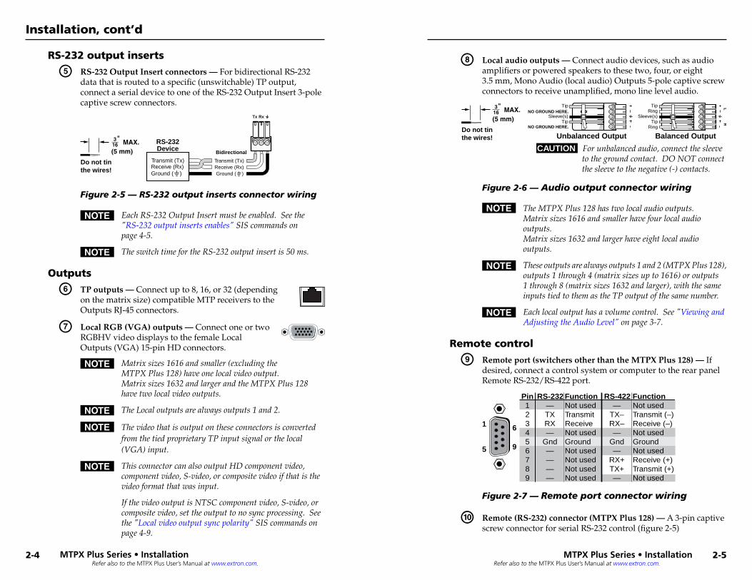
RS-232 output inserts
e RS-232 Output Insert connectors — For bidirectional RS-232 data that is routed to a specific (unswitchable) TP output, connect a serial device to one of the RS-232 Output Insert 3-pole captive screw connectors.
Receive (Rx)Transmit (Tx)
Ground ( )
Bidirectional
RS-232Device
Ground ( )Receive (Rx)Transmit (Tx)
RxTx
Do not tinthe wires!
Figure 2-5 — RS-232 output inserts connector wiring
N EachRS-232OutputInsertmustbeenabled.Seethe"RS-232outputinsertsenables"SIScommandsonpage4-5.
N TheswitchtimefortheRS-232outputinsertis50ms.
Outputs
f TP outputs — Connect up to 8, 16, or 32 (depending on the matrix size) compatible MTP receivers to the Outputs RJ-45 connectors.
g Local RGB (VGA) outputs — Connect one or two RGBHV video displays to the female Local Outputs (VGA) 15-pin HD connectors.
N Matrixsizes1616andsmaller(excludingtheMTPXPlus128)haveonelocalvideooutput.Matrixsizes1632andlargerandtheMTPXPlus128havetwolocalvideooutputs.
N TheLocaloutputsarealwaysoutputs1and2.
N ThevideothatisoutputontheseconnectorsisconvertedfromthetiedproprietaryTPinputsignalorthelocal(VGA)input.
N ThisconnectorcanalsooutputHDcomponentvideo,componentvideo,S-video,orcompositevideoifthatisthevideoformatthatwasinput.
IfthevideooutputisNTSCcomponentvideo,S-video,orcompositevideo,settheoutputtonosyncprocessing.Seethe"Localvideooutputsyncpolarity"SIScommandsonpage4-9.
h Local audio outputs — Connect audio devices, such as audio amplifiers or powered speakers to these two, four, or eight 3.5 mm, Mono Audio (local audio) Outputs 5-pole captive screw connectors to receive unamplified, mono line level audio.
Unbalanced Output Balanced Output
LR
RingTip
Sleeve(s)Tip
Ring
Sleeve(s)
Tip
Tip
NO GROUND HERE.
NO GROUND HERE.Do not tinthe wires!
CAUTION For unbalanced audio, connect the sleeve to the ground contact. DO NOT connect the sleeve to the negative (-) contacts.
Figure 2-6 — Audio output connector wiring
N TheMTPXPlus128hastwolocalaudiooutputs.Matrixsizes1616andsmallerhavefourlocalaudiooutputs.Matrixsizes1632andlargerhaveeightlocalaudiooutputs.
N Theseoutputsarealwaysoutputs1and2(MTPXPlus128),outputs1through4(matrixsizesupto1616)oroutputs1through8(matrixsizes1632andlarger),withthesameinputstiedtothemastheTPoutputofthesamenumber.
N Eachlocaloutputhasavolumecontrol.See"ViewingandAdjustingtheAudioLevel"onpage3-7.
Remote control
i Remote port (switchers other than the MTPX Plus 128) — If desired, connect a control system or computer to the rear panel Remote RS-232/RS-422 port.
RS-232 Function Pin Function1 2 3 4 5 6 7 8 9
— TX RX —
Gnd — — — —
Not usedTransmitReceiveNot usedGroundNot usedNot usedNot usedNot used
—TX–RX–—
Gnd—
RX+TX+—
Not usedTransmit (–)Receive (–)Not usedGroundNot usedReceive (+)Transmit (+)Not used
RS-422
5
1
9
6
Figure 2-7 — Remote port connector wiring
j Remote (RS-232) connector (MTPX Plus 128) — A 3-pin captive screw connector for serial RS-232 control (figure 2-5)
MTPX Pl�us Series • Instal�l�ation
Installation, cont’d
2-4 MTPX Pl�us Series • Instal�l�ation
2-5
Refer also to the MTPX Plus User’s Manual at www.extron.com.
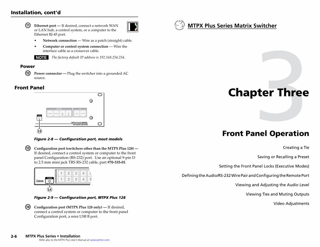
k Ethernet port — If desired, connect a network WAN or LAN hub, a control system, or a computer to the Ethernet RJ-45 port.
• Network connection — Wire as a patch (straight) cable.
• Computer or control system connection — Wire the interface cable as a crossover cable.
N ThefactorydefaultIPaddressis192.168.254.254.
Power
l Power connector — Plug the switcher into a grounded AC source.
Front Panel
AUDIOVIDEO
I/OCONTROL
ENTER PRESET VIEW ESC
CONFIG
MTPX PLUS SERIESMTP MATRIX SWITCHER
13
Figure 2-8 — Configuration port, most models
m Configuration port (switchers other than the MTPX Plus 128) — If desired, connect a control system or computer to the front panel Configuration (RS-232) port. Use an optional 9-pin D to 2.5 mm mini jack TRS RS-232 cable, part #70-335-01.
1
1
2
2
3
3
4
4
5
5
INPUT
OUTPUT
CONFIG
14
Figure 2-9 — Configuration port, MTPX Plus 128
n Configuration port (MTPX Plus 128 only) — If desired, connect a control system or computer to the front panel Configuration port, a mini USB B port.
3Chapter Three
Front Panel Operation
Creating.a.Tie
Saving.or.Recalling.a.Preset
Setting.the.Front.Panel.Locks.(Executive.Modes)
Defining.the.Audio/RS-232.Wire.Pair.and.Configuring.the.Remote.Port
Viewing.and.Adjusting.the.Audio.Level
Viewing.Ties.and.Muting.Outputs
Video.Adjustments
MTPX Pl�us Series • Instal�l�ation
Installation, cont’d
2-6
MTPX Pl�us Series Matrix Switcher
3-2Refer also to the MTPX Plus User’s Manual at www.extron.com.
3-3Refer also to the MTPX Plus User’s Manual at www.extron.com.
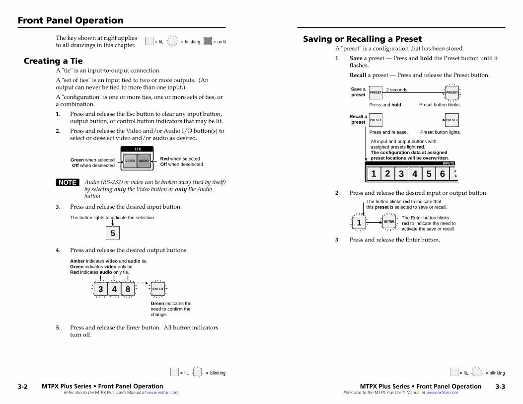
The key shown at right applies to all drawings in this chapter.
Creating a TieA "tie" is an input-to-output connection.
A "set of ties" is an input tied to two or more outputs. (An output can never be tied to more than one input.)
A "configuration" is one or more ties, one or more sets of ties, or a combination.
1. Press and release the Esc button to clear any input button, output button, or control button indicators that may be lit.
2. Press and release the Video and/or Audio I/O button(s) to select or deselect video and/or audio as desired.
Green when selectedOff when deselected
Red when selectedOff when deselected
I / O
VIDEO AUDIO
N Audio(RS-232)orvideocanbebrokenaway(tiedbyitself)byselectingonlytheVideobuttonoronlytheAudiobutton.
3. Press and release the desired input button.
5
The button lights to indicate the selection.
4. Press and release the desired output buttons.
3 4 ENTER8
Amber indicates video and audio tie.Green indicates video only tie.Red indicates audio only tie.
Green indicates the need to confirm the change.
5. Press and release the Enter button. All button indicators turn off.
Saving or Recalling a PresetA "preset" is a configuration that has been stored.
1. Save a preset — Press and hold the Preset button until it flashes.
Recall a preset — Press and release the Preset button.
PRESET PRESET
PRESET PRESET
Preset button blinks. Press and hold.
2 seconds Save a preset
Recall a preset
Preset button lights. Press and release.
All input and output buttons with assigned presets light red. The configuration data at assigned preset locations will be overwritten.
INPUTS
1 2 3 4 5 6 7
2. Press and release the desired input or output button.
1 ENTER
The button blinks red to indicate that this preset is selected to save or recall.
The Enter button blinks red to indicate the need to activate the save or recall.
3. Press and release the Enter button.
= lit, = unlit= blinking,
= lit, = unlit= blinking, = lit, = unlit= blinking,
MTPX Pl�us Series • Front Panel� Operation
Front Panel Operation
MTPX Pl�us Series • Front Panel� Operation
Refer also to the MTPX Plus User’s Manual at www.extron.com.
3-5Refer also to the MTPX Plus User’s Manual at www.extron.com.
Setting the Front Panel Locks (Executive Modes)The matrix switcher has three levels of front panel security lock that limit the operation of the switcher from the front panel. The three levels are:
• Lock mode 0 — The front panel is completely unlocked.• Lock mode 1 — All changes are locked from the front
panel (except for setting Lock mode 2). Some functions can be viewed.
• Lock mode 2 — Basic functions are unlocked. Advanced functions are locked and can be viewed only.
Basic functions consist of:m Making tiesm Saving and recalling presetsm Setting input audio gain and attenuationm Changing Lock modes
Advanced functions consist of:
m Setting audio output mutesm Setting audio output volumem Setting audio/RS-232 wire pair and front panel
configuration
N TheswitcherisshippedfromthefactoryinLockmode2.
Selecting Lock mode 2 or toggling between mode 2 and mode 0
N IftheswitcherisinLockmode0ormode1,thisprocedureselectsmode2.
IftheswitcherisinLockmode2,thisprocedureselectsmode0(unlockstheswitcher).
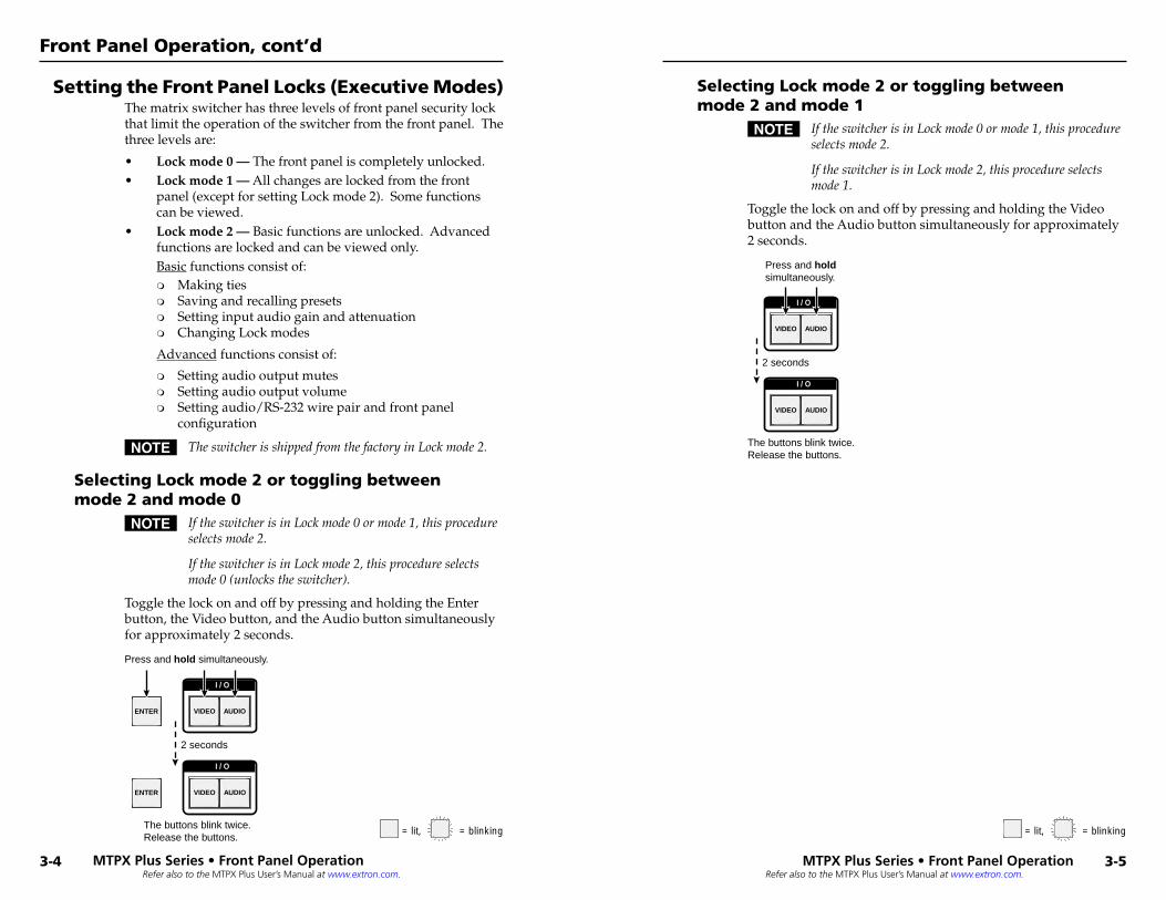
Toggle the lock on and off by pressing and holding the Enter button, the Video button, and the Audio button simultaneously for approximately 2 seconds.
I / O
VIDEO AUDIO ENTER
I / O
VIDEO AUDIOENTER
Press and hold simultaneously.
The buttons blink twice.Release the buttons.
2 seconds
Selecting Lock mode 2 or toggling between mode 2 and mode 1
N IftheswitcherisinLockmode0ormode1,thisprocedureselectsmode2.
IftheswitcherisinLockmode2,thisprocedureselectsmode1.
Toggle the lock on and off by pressing and holding the Video button and the Audio button simultaneously for approximately 2 seconds.
I / O
VIDEO AUDIO
I / O
VIDEO AUDIO
Press and hold simultaneously.
The buttons blink twice.Release the buttons.
2 seconds
= lit, = unlit= blinking, = lit, = unlit= blinking,
MTPX Pl�us Series • Front Panel� Operation
Front Panel Operation, cont’d
3-4 MTPX Pl�us Series • Front Panel� Operation
Refer also to the MTPX Plus User’s Manual at www.extron.com.
3-7Refer also to the MTPX Plus User’s Manual at www.extron.com.
Defining the Audio/RS-232 Wire Pair and Configuring the Remote Port
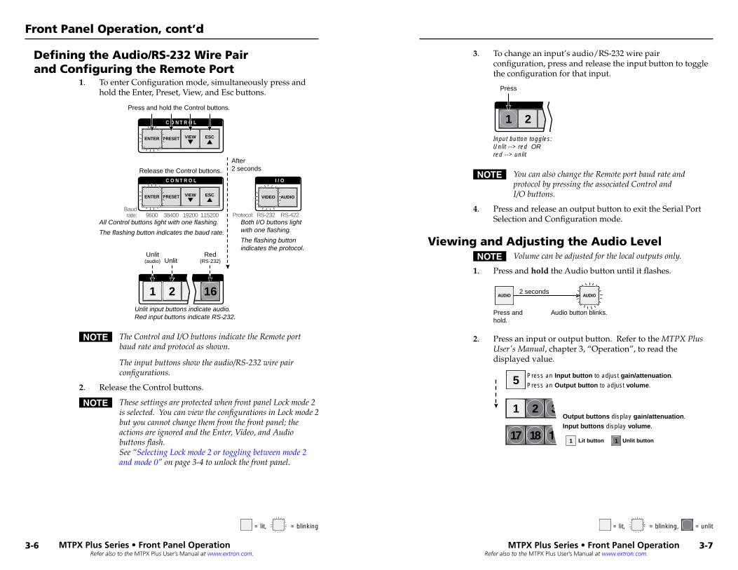
1. To enter Configuration mode, simultaneously press and hold the Enter, Preset, View, and Esc buttons.
I / O
VIDEO AUDIO
C O N T R O L
PRESETENTER ESCVIEW
C O N T R O L
PRESETENTER ESCVIEW
21 3 16
Protocol: RS-422RS-232
After2 seconds
Press and hold the Control buttons.
Release the Control buttons.
Both I/O buttons light with one flashing.
The flashing button indicates the protocol.
Unlit input buttons indicate audio.Red input buttons indicate RS-232.
Unlit Red
(RS-232)Unlit
(audio)
9600Baudrate: 1152001920038400
All Control buttons light with one flashing.
The flashing button indicates the baud rate.
N TheControlandI/ObuttonsindicatetheRemoteportbaudrateandprotocolasshown.
Theinputbuttonsshowtheaudio/RS-232wirepairconfigurations.
2. Release the Control buttons.
N ThesesettingsareprotectedwhenfrontpanelLockmode2isselected.YoucanviewtheconfigurationsinLockmode2butyoucannotchangethemfromthefrontpanel;theactionsareignoredandtheEnter,Video,andAudiobuttonsflash.See“SelectingLockmode2ortogglingbetweenmode2andmode0”onpage3-4tounlockthefrontpanel.
3. To change an input’s audio/RS-232 wire pair configuration, press and release the input button to toggle the configuration for that input.
21 3
Input button toggles:Unlit --> red ORred --> unlit
Press
N YoucanalsochangetheRemoteportbaudrateandprotocolbypressingtheassociatedControlandI/Obuttons.
4. Press and release an output button to exit the Serial Port Selection and Configuration mode.
Viewing and Adjusting the Audio LevelN Volumecanbeadjustedforthelocaloutputsonly.
1. Press and hold the Audio button until it flashes.
AUDIO AUDIO
Audio button blinks.Press and hold.
2 seconds
2. Press an input or output button. Refer to the MTPXPlusUser'sManual, chapter 3, “Operation”, to read the displayed value.
17 18
1 2
5 Press an Input button to adjust gain/attenuation.
Press an Output button to adjust volume.
Output buttons display gain/attenuation.
Input buttons display volume.
1Lit button Unlit button1
= lit, = unlit= blinking, = lit, = unlit= blinking,
MTPX Pl�us Series • Front Panel� Operation
Front Panel Operation, cont’d
3-6 MTPX Pl�us Series • Front Panel� Operation
Refer also to the MTPX Plus User’s Manual at www.extron.com.
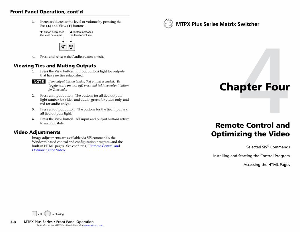
3. Increase/decrease the level or volume by pressing the Esc (>) and View (<) buttons.
ESC VIEW
button decreases the level or volume.
button increases the level or volume.
4. Press and release the Audio button to exit.
Viewing Ties and Muting Outputs1. Press the View button. Output buttons light for outputs
that have no ties established.
N Ifanoutputbuttonblinks,thatoutputismuted.To toggle mute on and off,pressandholdtheoutputbuttonfor2seconds.
2. Press an input button. The buttons for all tied outputs light (amber for video and audio, green for video only, and red for audio only).
3. Press an output button. The buttons for the tied input and all tied outputs light.
4. Press the View button. All input and output buttons return to an unlit state.
Video AdjustmentsImage adjustments are available via SIS commands, the Windows-based control and configuration program, and the built-in HTML pages. See chapter 4, “Remote Control and Optimizing the Video”.
4Chapter Four
Remote Control and Optimizing the Video
Selected.SIS™.Commands
Installing.and.Starting.the.Control.Program
Accessing.the.HTML.Pages
= lit, = unlit= blinking,
MTPX Pl�us Series • Front Panel� Operation
Front Panel Operation, cont’d
3-8
MTPX Pl�us Series Matrix Switcher
4-2Refer also to the MTPX Plus User’s Manual at www.extron.com.
Refer also to the MTPX Plus User’s Manual at www.extron.com.
Selected SIS™ CommandsYou can use Simple Instruction Set (SIS) commands for operation and configuration of the switchers. You can run these commands from a PC connected to a serial port (i, j, and m on pages 2-5 and 2-6), Ethernet port (k), or USB port (n) on the switcher.
Establishing a network (Ethernet) connectionN IfyouconnecttotheswitcherviatheLANport,andit
isthefirsttimeyouhavedoneso,youmaychangethedefaultsettings(IPaddress,subnetmask,and[optional]administratornameandpassword)ofthecontroller.See"ConfiguringforNetworkCommunication"onpage4-24fordetails.
Establish a network connection as follows:
1. Open a TCP socket to port 23 using the IP address of the switcher.
N ThefactorydefaultIPaddressis192.168.254.254.
The switcher responds with a copyright message including the date, the name of the product, firmware version, part number, and the current date and time.
N Iftheswitcherisnotpassword-protected,thedeviceisnowreadytoacceptSIScommands.
N Iftheswitcherispassword-protected,apasswordpromptappears.
2. If the switcher is password-protected, enter the appropriate password.
If the password is accepted, the switcher responds with Login User or Login Administrator.
If the password is not accepted, the Password prompt reappears.
Connection timeoutsThe Ethernet link times out and disconnects after a designated period of time of no communications. By default, this timeout value is set to 5 minutes but the value can be changed. See the Configure port timeout SIS command on page 4-14.
N Extronrecommendsleavingthedefaulttimeoutat5minutesandperiodicallyissuingtheQuery(Q)commandtokeeptheconnectionactiveordisconnectingthesocketandreopeningtheconnectionwhennecessary.
Number of connectionsA switcher can have up to 200 simultaneous TCP connections, including all HTTP sockets and Telnet connections. When the connection limit is reached, the switcher accepts no new connections until some have been closed. No error message or indication is given that the connection limit has been reached. To maximize performance of your switcher, keep the number of connections low and close unnecessary open sockets.
Verbose modeTelnet connections to a switcher can be used to monitor for changes that occur on the switcher, such as front panel operations and SIS commands from other Telnet sockets or a serial port. For a Telnet session to receive change notices from the switcher, the Telnet session must be in verbose mode 1 or 3. See the Set verbose mode SIS command on page 4-14. In verbose mode 3, the Telnet socket reports changes using messages that resemble SIS command responses.
Establishing a USB port connectionA standard USB cable and the Extron DataViewer utility, version 2.0 or newer, can be used for connection to the MTPX Plus 128 Configuration port. The USB cable, available at any local electronics store, should be terminated on one end with a mini USB B male connector
N BeforeyouusetheUSBportforthefirsttime,installtheUSBdriveronyourcomputer.Thesimplestwaytodothisistoinstallversion7.7orneweroftheMatrixSwitchersControlProgramandthenruntheFoundNewHardwareWizard.See“Installingtheprogram,“onpage4-5and“First-timeconnectionconsiderations“onpage4-16.
Host-to-switcher instructionsThe switcher accepts SIS commands through either serial port, the USB port, or the LAN port. SIS commands consist of one or more characters per command field. They do not require any special characters to begin or end the command character sequence. Each switcher response to an SIS command ends with a carriage return and a line feed (CR/LF = ]), which signals the end of the response character string. A string is one or more characters.
N ThetablethatbeginsonthenextpageisapartiallistofSIScommands.Foracompletelisting,refertotheMTPX Plus User's Manual.
MTPX Plus Series • Remote Control and Optimizing the Video
Remote Control and Optimizing the Video
MTPX Plus Series • Remote Control and Optimizing the Video
4-3
Refer also to the MTPX
Plus User’s M
anual at ww
w.extron.com
.
Refer also to the MTPX
Plus User’s M
anual at ww
w.extron.com
.
Command ASCII command(host to switcher)
Response(switcher to host)
Additional description
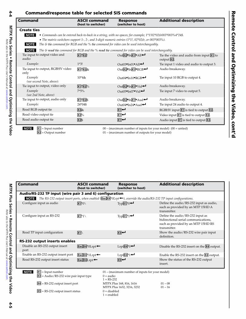
Create tiesN •Commandscanbeenteredback-to-backinastring,withnospaces;forexample;1*1!02*02&003*003%4*24$.
•Thematrixswitcherssupport1-,2-,and3-digitnumericentries(1*1!,02*02&,or003*003%).N The& tiecommandforRGBandthe%tiecommandforvideocanbeusedinterchangeably.
N The&read tiecommandforRGBandthe%read tiecommandforvideocanbeusedinterchangeably.Tie input to output video and audio
X!*X@! OutX@•InX!•All] Tie the video and audio from input X! to output X@.
Example: 1*3! Out03•In01•All] Tie input 1 video and audio to output 3. Tie input to output, RGBHV video only
X!*X@& OutX@•InX!•RGB] Audio breakaway.
Example(seesecondNote,above):
10*4& Out04•In10•RGB] Tie input 10 RGB to output 4.
Tie input to output, video only X!*X@% OutX@•InX!•Vid] Audio breakaway.
Example(see2ndNote,above)
7*5% Out05•In07•Vid] Tie input 7 video to output 5.
Tie input to output, audio only X!*X@$ OutX@•InX!•Aud] Audio breakaway.
Example: 24*04$ Out04•In24•Aud] Tie input 24 audio to output 4.
Read RGB output tie X@& X!] RGBHV input X! is tied to output [email protected] video output tie X@% X!] Video input X! is tied to output [email protected] audio output tie X@$ X!] Audio input X! is tied to output X@.
Command ASCII command(host to switcher)
Response(switcher to host)
Additional description
Audio/RS-232 TP input (wire pair 3 and 6) configurationN TheRS-232outputinsertports,whenenabled(EX$*0Lrpt}),overridetheaudio/RS-232TPinputconfigurations.
Configure input as audio X!*0\ TypX!*0] Define the audio/RS-232 input as audio, such as provided by an MTP 15HD A transmitter.
Configure input as RS-232 X!*1\ TypX!*1] Define the audio/RS-232 input as bidirectional serial communications, such as provided by an MTP 15HD RS transmitter.
Read TP input configuration X!\ X#] Show the audio/RS-232 wire pair input definition.
RS-232 output inserts enablesDisable an RS-232 output insert port
EX$*0Lrpt} LrptX$*0] Disable the RS-232 insert on the X$ output.
Enable an RS-232 output insert port EX$*1Lrpt} LrptX$*1] Enable the RS-232 insert on the X$ output.Read RS-232 output insert status EX$Lrpt} X%] Show the status of the RS-232 output
insert.
N X! = Input number 00 – (maximum number of inputs for your model) (00 = untied)X@ = Output number 01 – (maximum number of outputs for your model)
N X! = Input number 01 – (maximum number of inputs for your model)X# = Audio/RS-232 wire pair input type 0 = audio 1 = RS-232 X$ = RS-232 output insert port MTPX Plus 168, 816, 1616 01 – 08 MTPX Plus 1632, 3216, 3232 01 – 16 X% = RS-232 output insert status 0 = disabled 1 = enabled
Command/response table for selected SIS commands
MTPX
Pl�us Series • R
emo
te Co
ntro
l� and
Op
timizin
g th
e Vid
eo
Rem
ote
Co
ntro
l an
d O
ptim
izing
the V
ideo
, con
t’d
4-4
MTPX
Pl�us Series • R
emo
te Co
ntro
l� and
Op
timizin
g th
e Vid
eo
4-5
Refer also to the MTPX
Plus User’s M
anual at ww
w.extron.com
.
Refer also to the MTPX
Plus User’s M
anual at ww
w.extron.com
.
Command ASCII command
(host to switcher) Response(switcher to host)
Additional description
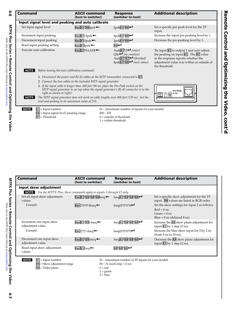
Input signal level and peaking and auto calibrateSet input signal level EX!*X^Ipek} IpekX!*X^] Set a specific pre-peak level for the TP
input.Increment input peaking EX!+Ipek} IpekX!*X^] Increase the input pre-peaking level by 1.
Decrement input peaking EX!-Ipek} IpekX!*X^] Decrease the pre-peaking level by 1.
Read input peaking setting EX!Ipek} X^]Execute auto calibration EX!*0AADJ} AadjX!*2] {start}
Qik] {tiecreation}AadjX!*X&] {finished}IpekX!*X^] {newvalue}
Tie input X! to output 1 and auto adjust the peaking on input X!. The X& value in the response reports whether the adjustment value was within or outside of the threshold.
N Beforeissuingtheautocalibrationcommand:
1. DisconnectthepowerandRJ-45cablesattheMTPtransmitterconnectedtoX!.2. ConnectthetwocablestotheincludedMTPsignalgenerator.3. Iftheinputcableislongerthan300feet(90m),placethePre-Peakswitchonthe
MTPsignalgeneratortoon(upwhenthesignalgenerator‘sRJ-45connectoristotherightasshownatright).
N TheMTPsignalgeneratordoesnotworkoncablelengthsover400feet(120m).Setthelevelandpeakingtoitsmaximumvalueof255.
Pre-Peakis on.
Command ASCII command(host to switcher)
Response(switcher to host)
Additional description
Input skew adjustmentN FortheMTPXPlus,thesecommandsapplytoinputs5through12only.
Set all input skew adjustment values
EX!*X**X**X*Iseq} IseqX!*X**X**X*] Set a specific skew adjustment for the TP input. X* values are listed in RGB order.
Example: E2*0*0*4Iseq} Iseq02*0*0*4] Set the skew settings for input 2 as follows:Red = 0 ns Green = 0 ns Blue = 8 ns (delayed 8 ns)
Increment one input skew adjustment value
EX!*X(+Iseq} IseqX!*X**X**X*] Increase the X( skew plane adjustment for input X! by 1 step (2 ns).
Example: E2*2*+Iseq} Iseq02*0*0*5] Increase the blue skew input for 2 by 2 ns (from 8 ns to 10 ns).
Decrement one input skew adjustment value
EX!*X(-Iseq} IseqX!*X**X**X*] Decrease the X( skew plane adjustment for input X! by 1 step (2 ns).
Read input skew adjustment values
EX!Iseq} X**X**X*]
N X! = Input number 01 – (maximum number of inputs for your model)X^ = Input signal level/peaking range 000 – 255X& = Threshold 0 = outside of threshold 1 = within threshold
N X! = Input number 01 – (maximum number of TP inputs for your model)X* = Skew adjustment range 00 – 31 (each step = 2 ns)X( = Video plane 0 = red 1 = green 2 = blue
MTPX
Pl�us Series • R
emo
te Co
ntro
l� and
Op
timizin
g th
e Vid
eo
Rem
ote
Co
ntro
l an
d O
ptim
izing
the V
ideo
, con
t’d
4-6
MTPX
Pl�us Series • R
emo
te Co
ntro
l� and
Op
timizin
g th
e Vid
eo
4-7
Refer also to the MTPX
Plus User’s M
anual at ww
w.extron.com
.
Refer also to the MTPX
Plus User’s M
anual at ww
w.extron.com
.
Command ASCII command
(host to switcher) Response(switcher to host)
Additional description
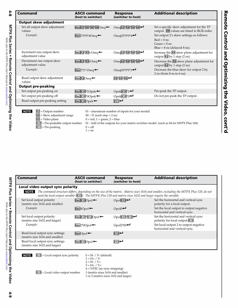
Output skew adjustmentSet all output skew adjustment values
EX@*X**X**X*Oseq} OseqX@*X**X**X*] Set a specific skew adjustment for the TP output. X* values are listed in RGB order.
Example: E2*0*0*4Oseq} Oseq02*0*0*4] Set output 2’s skew settings as follows:Red = 0 ns Green = 0 ns Blue = 8 ns (delayed 8 ns).
Increment one output skew adjustment value
EX@*X(+Oseq} OseqX@*X**X**X*] Increase the X( skew plane adjustment for output X@ by 1 step (2 ns).
Decrement one output skew adjustment value
EX@*X(-Oseq} OseqX@*X**X**X*] Decrease the X( skew plane adjustment for output X@ by 1 step (2 ns).
Example: E2*2*-Oseq} Oseq02*0*0*3] Decrease the blue skew for output 2 by 2 ns (from 8 ns to 6 ns).
Read output skew adjustment values
EX@Oseq} X**X**X*]
Output pre-peakingSet output pre-peaking on EX1)*1Opek} OpekX1)*1] Pre-peak the TP output.
Set output pre-peaking off EX1)*0Opek} OpekX1)*0] Do not pre-peak the TP output.
Read output pre-peaking setting EX1)Opek} X1!]
Command ASCII command(host to switcher)
Response(switcher to host)
Additional description
Local video output sync polarityN Thecommandstructurediffers,dependingonthesizeofthematrix.Matrixsizes1616andsmaller,excludingtheMTPXPlus128,donot
needthelocaloutputvariable(X1#).TheMTPXPlus128andmatrixsizes1632andlargerrequirethevariable.Set local output polarity (matrix size 1616 and smaller)
EX1@Opol} OpolX1@] Set the horizontal and vertical sync polarity for a local output.
Example: E0Opol} Opol0] Set the local output to output negative horizontal and vertical sync.
Set local output polarity (matrix size 1632 and larger)
EX1#*X1@Opol} OpolX1#*X1@] Set the horizontal and vertical sync polarity for local output X1#.
Example: E2*0Opol} Opol2*00] Set local output 2 to output negative horizontal and vertical sync.
Read local output sync settings (matrix size 1616 and smaller)
EOpol} X1@]
Read local output sync settings (matrix size 1632 and larger)
EX1#Opol} X1@]
N X1@ = Local output sync polarity 0 = H- / V- (default) 1 = H+ / V- 2 = H- / V+ 3 = H+ / V+ 4 = NTSC (no sync stripping) X1# = Local video output number 1 (matrix sizes 1616 and smaller) 1 or 2 (matrix sizes 1632 and larger)
N X@ = Output number 01 – (maximum number of inputs for your model)X* = Skew adjustment range 00 – 31 (each step = 2 ns)X( = Video plane 0 = red, 1 = green, 2 = blueX1) = Pre-peakable output number 01 – half of the outputs for your matrix switcher model (such as 04 for MTPX Plus 168)X1! = Pre-peaking 0 = off 1 = on
MTPX
Pl�us Series • R
emo
te Co
ntro
l� and
Op
timizin
g th
e Vid
eo
Rem
ote
Co
ntro
l an
d O
ptim
izing
the V
ideo
, con
t’d
4-8
MTPX
Pl�us Series • R
emo
te Co
ntro
l� and
Op
timizin
g th
e Vid
eo
4-9
Refer also to the MTPX
Plus User’s M
anual at ww
w.extron.com
.
Refer also to the MTPX
Plus User’s M
anual at ww
w.extron.com
.
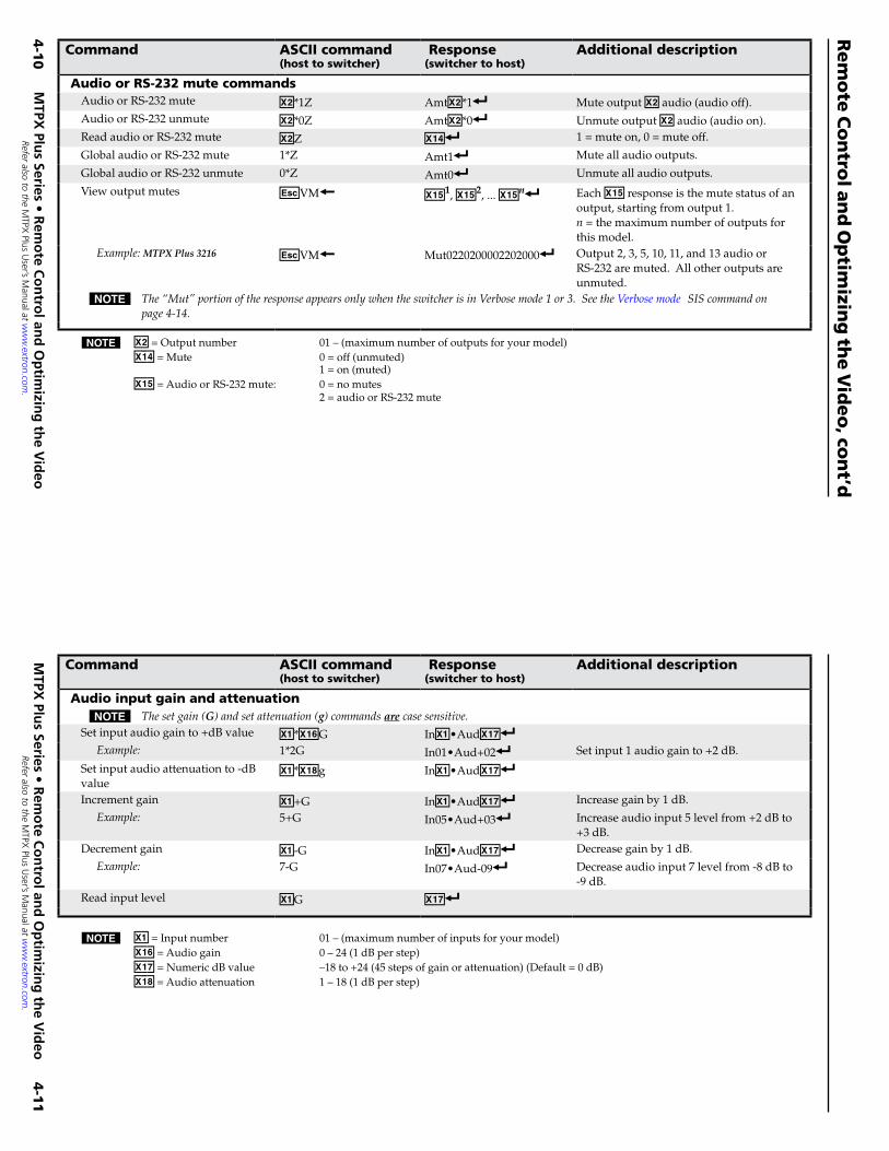
N X! = Input number 01 – (maximum number of inputs for your model)X1^ = Audio gain 0 – 24 (1 dB per step)X1& = Numeric dB value –18 to +24 (45 steps of gain or attenuation) (Default = 0 dB)X1* = Audio attenuation 1 – 18 (1 dB per step)
N X@ = Output number 01 – (maximum number of outputs for your model)X1$ = Mute 0 = off (unmuted) 1 = on (muted) X1% = Audio or RS-232 mute: 0 = no mutes 2 = audio or RS-232 mute
Command ASCII command(host to switcher)
Response(switcher to host)
Additional description
Audio or RS-232 mute commandsAudio or RS-232 mute X@*1Z AmtX@*1] Mute output X@ audio (audio off).Audio or RS-232 unmute X@*0Z AmtX@*0] Unmute output X@ audio (audio on).Read audio or RS-232 mute X@Z X1$] 1 = mute on, 0 = mute off.
Global audio or RS-232 mute 1*Z Amt1] Mute all audio outputs.
Global audio or RS-232 unmute 0*Z Amt0] Unmute all audio outputs.
View output mutes EVM} X1%1, X1%2, ... X1%n] Each X1% response is the mute status of an output, starting from output 1. n = the maximum number of outputs for this model.
Example:MTPX Plus 3216 EVM} Mut0220200002202000] Output 2, 3, 5, 10, 11, and 13 audio or RS-232 are muted. All other outputs are unmuted.
N The“Mut”portionoftheresponseappearsonlywhentheswitcherisinVerbosemode1or3.SeetheVerbosemode SIScommandonpage4-14.
Command ASCII command(host to switcher)
Response(switcher to host)
Additional description
Audio input gain and attenuationN Thesetgain(G)andsetattenuation(g)commandsarecasesensitive.
Set input audio gain to +dB value X!*X1^G InX!•AudX1&]Example: 1*2G In01•Aud+02] Set input 1 audio gain to +2 dB.
Set input audio attenuation to -dB value
X!*X1*g InX!•AudX1&]
Increment gain X!+G InX!•AudX1&] Increase gain by 1 dB.
Example: 5+G In05•Aud+03] Increase audio input 5 level from +2 dB to +3 dB.
Decrement gain X!-G InX!•AudX1&] Decrease gain by 1 dB.
Example: 7-G In07•Aud-09] Decrease audio input 7 level from -8 dB to -9 dB.
Read input level X!G X1&]
MTPX
Pl�us Series • R
emo
te Co
ntro
l� and
Op
timizin
g th
e Vid
eo
Rem
ote
Co
ntro
l an
d O
ptim
izing
the V
ideo
, con
t’d
4-1
0M
TPX Pl�u
s Series • Rem
ote C
on
trol� an
d O
ptim
izing
the V
ideo
4-1
1
Refer also to the MTPX
Plus User’s M
anual at ww
w.extron.com
.
Refer also to the MTPX
Plus User’s M
anual at ww
w.extron.com
.
Command ASCII command
(host to switcher) Response(switcher to host)
Additional description
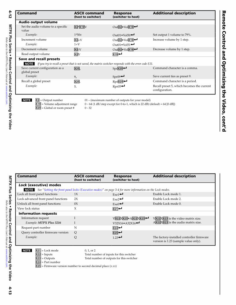
Audio output volumeSet the audio volume to a specific value
X@*X1(V OutX@•VolX1(]
Example: 1*50v Out01•Vol50] Set output 1 volume to 79%.
Increment volume X@+V OutX@•VolX1(] Increase volume by 1 step.
Example: 1+V Out01•Vol51]Decrement volume X@-V OutX@•VolX1(] Decrease volume by 1 step.
Read output volume X@V X1(]Save and recall presets
N Ifyoutrytorecallapresetthatisnotsaved,thematrixswitcherrespondswiththeerrorcodeE11.Save current configuration as a global preset
X2), SprX2)] Command character is a comma.
Example: 9, Spr09] Save current ties as preset 9.
Recall a global preset X2). RprX2)] Command character is a period.
Example: 5. Rpr05] Recall preset 5, which becomes the current configuration.
N X@ = Output number 01 – (maximum number of outputs for your model)X1( = Volume adjustment range 0 – 64 (1 dB/step except for 0-to-1, which is 22 dB) (default = 64 [0 dB])X2) = Global or room preset # 0 - 32
N X2! = Lock mode 0, 1, or 2X2@ = Inputs Total number of inputs for this switcherX2# = Outputs Total number of outputs for this switcherX2$ = Part numberX2% = Firmware version number to second decimal place (x.xx)
Command ASCII command(host to switcher)
Response(switcher to host)
Additional description
Lock (executive) modesN See“Settingthefrontpanellocks(Executivemodes)”onpage3-4formoreinformationontheLockmodes.
Lock all front panel functions 1X Exe1] Enable Lock mode 1.
Lock advanced front panel functions 2X Exe2] Enable Lock mode 2.
Unlock all front panel functions 0X Exe0] Enable Lock mode 0.
View lock status X X2!]Information requests
Information request I VX2@XX2#•AX2@XX2#] VX2@XX2# is the video matrix size. AX2@XX2# is the audio matrix size.Example:MTPX Plus 3216 I V32X16•A32X16]
Request part number N X2$]Query controller firmware version Q X2%]
Example: Q 1.23] The factory-installed controller firmware version is 1.23 (sample value only).
MTPX
Pl�us Series • R
emo
te Co
ntro
l� and
Op
timizin
g th
e Vid
eo
Rem
ote
Co
ntro
l an
d O
ptim
izing
the V
ideo
, con
t’d
4-1
2M
TPX Pl�u
s Series • Rem
ote C
on
trol� an
d O
ptim
izing
the V
ideo
4-1
3
Refer also to the MTPX
Plus User’s M
anual at ww
w.extron.com
.
Refer also to the MTPX
Plus User’s M
anual at ww
w.extron.com
.
Command ASCII command(host to switcher)
Response(switcher to host)
Additional description
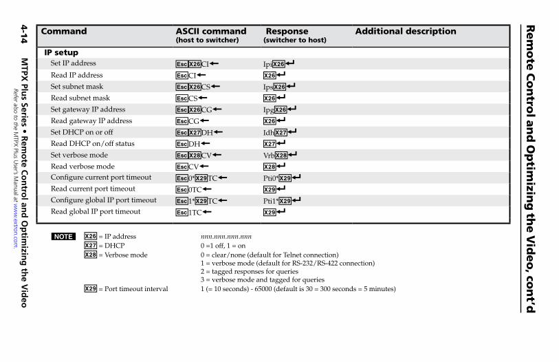
IP setupSet IP address EX2^CI} IpiX2^]Read IP address ECI} X2^]Set subnet mask EX2^CS} IpsX2^]Read subnet mask ECS} X2^]Set gateway IP address EX2^CG} IpgX2^]Read gateway IP address ECG} X2^]Set DHCP on or off EX2&DH} IdhX2&]Read DHCP on/off status EDH} X2&]Set verbose mode EX2*CV} VrbX2*]Read verbose mode ECV} X2*]Configure current port timeout E0*X2(TC} Pti0*X2(]Read current port timeout E0TC} X2(]Configure global IP port timeout E1*X2(TC} Pti1*X2(]Read global IP port timeout E1TC} X2(]
N X2^ = IP address nnn.nnn.nnn.nnnX2& = DHCP 0 =1 off, 1 = onX2* = Verbose mode 0 = clear/none (default for Telnet connection) 1 = verbose mode (default for RS-232/RS-422 connection) 2 = tagged responses for queries 3 = verbose mode and tagged for queries X2( = Port timeout interval 1 (= 10 seconds) - 65000 (default is 30 = 300 seconds = 5 minutes)
Insta
lling
an
d S
tartin
g th
e C
on
trol P
rog
ram
Another w
ay to operate the switcher, to set the skew
ad
justments, the level and
peaking, and the output pre-peaking
(see "Optim
izing the video", beginning on page 4-18), is via
the Wind
ows
®-based M
atrix Switchers C
ontrol Program.
This program
is contained on the E
xtron Software Prod
ucts D
VD
(included
with the sw
itcher). Run this program
on a PC
connected to a serial port (i
, j, and
m on pages 2-5 and
2-6), E
thernet port (k), or U
SB port (n
) on the switcher. T
he program
must be installed
on a Wind
ows-based
computer and
cannot be run from
the DV
D.
N
Fordetailsonoperatingtheprogram,refertothe
MT
PX Plus U
ser's Manual,chapter5,“M
atrixSoftw
are”.
Insta
lling
the p
rog
ram
N
Torunthisprogramw
hileyourcomputerisconnected
toanMT
PX
Plus128C
onfiguration(USB
)port,useversion7.7ornew
eroftheMatrixSw
itchersControl
Program
.
1. Insert the D
VD
into the drive. T
he Extron softw
are DV
D
wind
ow should
appear automatically.
N
Ifthewindow
doesnotself-open,runLaunch.exefromthe
DV
D.
T
he Extron softw
are DV
D w
indow
appears.
2. C
lick the Softw
are tab.
3. Scroll to the M
atrix Switchers program
and click
Install.
MTPX
Pl�us Series • R
emo
te Co
ntro
l� and
Op
timizin
g th
e Vid
eo
Rem
ote
Co
ntro
l an
d O
ptim
izing
the V
ideo
, con
t’d
4-1
4M
TPX Pl�u
s Series • Rem
ote C
on
trol� an
d O
ptim
izing
the V
ideo
4-1
5
Refer also to the MTPX Plus User’s Manual at www.extron.com.
Refer also to the MTPX Plus User’s Manual at www.extron.com.
Co
mm
an
dA
SC
II c
om
man
d(h
ost
to
sw
itch
er)
Resp
on
se(s
wit
cher
to h
ost
)A
dd
itio
nal
desc
rip
tio
n
IP s
etu
pSe
t IP
add
ress
EX2^ C
I}Ip
iX2^]
Rea
d IP
ad
dre
ssE
CI}
X2^]
Set s
ubne
t mas
kE
X2^ C
S}Ip
sX2^]
Rea
d s
ubne
t mas
kE
CS}
X2^]
Set g
atew
ay IP
ad
dre
ssE
X2^ C
G}
IpgX2^]
Rea
d g
atew
ay IP
ad
dre
ssE
CG}
X2^]
Set D
HC
P on
or
off
EX2& D
H}
IdhX2&]
Rea
d D
HC
P on
/of
f sta
tus
ED
H}
X2&]
Set v
erbo
se m
ode
EX2* C
V}
VrbX2*]
Rea
d v
erbo
se m
ode
EC
V}
X2*]
Con
figur
e cu
rren
t por
t tim
eout
E0*X2( T
C}
Pti0
*X2(]
Rea
d c
urre
nt p
ort t
imeo
utE
0TC}
X2(]
Con
figur
e gl
obal
IP p
ort t
imeo
utE
1*X2( T
C}
Pti1
*X2(]
Rea
d g
loba
l IP
port
tim
eout
E1T
C}
X2(]
N X2^
= IP
ad
dre
ss
nnn.
nnn.
nnn.
nnn
X2&
= D
HC
P 0
=1
off,
1 =
on
X2*
= V
erbo
se m
ode
0 =
cle
ar/
none
(def
ault
for
Teln
et c
onne
ctio
n)
1 =
ver
bose
mod
e (d
efau
lt fo
r R
S-23
2/R
S-42
2 co
nnec
tion
)
2 =
tagg
ed r
espo
nses
for
quer
ies
3
= v
erbo
se m
ode
and
tagg
ed fo
r qu
erie
s X2(
= P
ort t
imeo
ut in
terv
al
1 (=
10
seco
nds)
- 65
000
(def
ault
is 3
0 =
300
sec
ond
s =
5 m
inut
es)
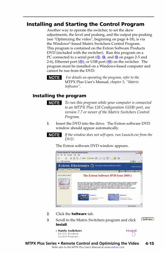
Installing and Starting the Control ProgramAnother way to operate the switcher, to set the skew adjustments, the level and peaking, and the output pre-peaking (see "Optimizing the video", beginning on page 4-18), is via the Windows®-based Matrix Switchers Control Program. This program is contained on the Extron Software Products DVD (included with the switcher). Run this program on a PC connected to a serial port (i, j, and m on pages 2-5 and 2-6), Ethernet port (k), or USB port (n) on the switcher. The program must be installed on a Windows-based computer and cannot be run from the DVD.
N Fordetailsonoperatingtheprogram,refertotheMTPX Plus User's Manual,chapter5,“MatrixSoftware”.
Installing the program
N TorunthisprogramwhileyourcomputerisconnectedtoanMTPXPlus128Configuration(USB)port,useversion7.7orneweroftheMatrixSwitchersControlProgram.
1. Insert the DVD into the drive. The Extron software DVD window should appear automatically.
N Ifthewindowdoesnotself-open,runLaunch.exefromtheDVD.
The Extron software DVD window appears.
2. Click the Software tab.
3. Scroll to the Matrix Switchers program and click Install.
MTPX Pl�us Series • Remote Control� and Optimizing the Video
Remote Control and Optimizing the Video, cont’d
4-14 MTPX Pl�us Series • Remote Control� and Optimizing the Video
4-15
Refer also to the MTPX Plus User’s Manual at www.extron.com.
Refer also to the MTPX Plus User’s Manual at www.extron.com.
4. Follow the on-screen instructions. The installation program creates a C:\Program Files\Extron\ Matrix_Switchers directory and an “Extron Electronics\Matrix Switchers” group folder. It installs the following four programs:
• MATRIX Switcher+ Control Program• MATRIX Switcher+ Help• Uninstall MATRIX Switcher• Check for Matrix Updates
First-time connection considerations
LAN port connectionIf you connect your PC to the switcher via the LAN port, and it is the first time you have done so, you may change the default settings (IP address, subnet mask, and [optional] administrator name and password) on the controller. See "Configuring for Network Communication" on page 4-24 for details.
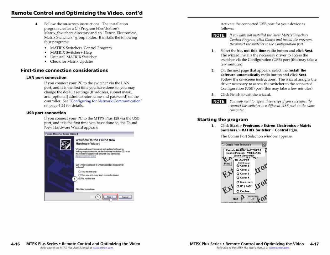
USB port connectionIf you connect your PC to the MTPX Plus 128 via the USB port, and it is the first time you have done so, the Found New Hardware Wizard appears.
1
1
Activate the connected USB port for your device as follows:
N IfyouhavenotinstalledthelatestMatrixSwitchersControlProgram,clickCancelandinstalltheprogram.ReconnecttheswitchertotheConfigurationport.
1. Select the No, not this time radio button and click Next. The wizard installs the necessary driver to access the switcher via the Configuration (USB) port (this may take a few minutes).
2. On the next page that appears, select the Install the software automatically radio button and click Next. Follow the on-screen instructions. The wizard assigns the driver necessary to access the switcher to the connected Configuration (USB) port (this may take a few minutes).
3. Click Finish to exit the wizard.
N YoumayneedtorepeatthesestepsifyousubsequentlyconnecttheswitchertoadifferentUSBportonthesamecomputer.
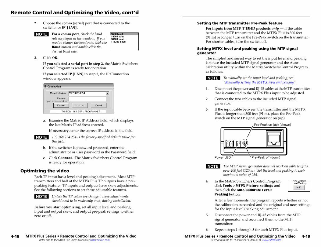
Starting the program1. Click Start > Programs > Extron Electronics > Matrix
Switchers > MATRIX Switcher + Control Pgm.
The Comm Port Selection window appears.
MTPX Plus Series • Remote Control and Optimizing the Video
Remote Control and Optimizing the Video, cont’d
4-16 MTPX Plus Series • Remote Control and Optimizing the Video
4-17
Refer also to the MTPX Plus User’s Manual at www.extron.com.
Refer also to the MTPX Plus User’s Manual at www.extron.com.
2. Choose the comm (serial) port that is connected to the switcher or IP [LAN].
N For a comm port,checkthebaudratedisplayedinthewindow.Ifyouneedtochangethebaudrate,clicktheBaudbuttonanddouble-clickthedesiredbaudrate.
3. Click OK.
If you selected a serial port in step 2, the Matrix Switchers Control Program is ready for operation.
If you selected IP [LAN] in step 2, the IP Connection window appears.
a. Examine the Matrix IP Address field, which displays the last Matrix IP address entered.
If necessary, enter the correct IP address in the field.
N 192.168.254.254isthefactory-specifieddefaultvalueforthisfield.
b. If the switcher is password protected, enter the administrator or user password in the Password field.
c. Click Connect. The Matrix Switchers Control Program is ready for operation.
Optimizing the videoEach TP input has a level and peaking adjustment. Most MTP transmitters and half of the MTPX Plus TP outputs have a pre-peaking feature. TP inputs and outputs have skew adjustments. See the following sections to set these adjustable features.
N UnlesstheTPcablesarechanged,theseadjustmentsshouldneedtobemadeonlyonce,duringinstallation.
Before you start optimizing, set all input level and peaking, input and output skew, and output pre-peak settings to either zero or off.
Setting the MTP transmitter Pre-Peak featureFor inputs from MTP T 15HD products only — If the cable between the MTP transmitter and the MTPX Plus is 300 feet (91 m) or longer, turn on the Pre-Peak switch on the transmitter. For shorter cables, turn the switch off.
Setting MTPX level and peaking using the MTP signal generator
The simplest and surest way to set the input level and peaking is to use the included MTP signal generator and the Auto-calibration utility within the Matrix Switchers Control Program as follows:
N Tomanuallysettheinputlevelandpeaking,see"ManuallysettingtheMTPXlevelandpeaking".
1. Disconnect the power and RJ-45 cables at the MTP transmitter that is connected to the MTPX Plus input to be adjusted.
2. Connect the two cables to the included MTP signal generator.
3. If the input cable between the transmitter and the MTPX Plus is longer than 300 feet (91 m), place the Pre-Peak switch on the MTP signal generator on (up).
Pre-Peak on (up) (shown)
Pre-Peak off (down)Power LED
N TheMTPsignalgeneratordoesnotworkoncablelengthsover400feet(120m).Setthelevelandpeakingtotheirmaximumvalueof255.
4. In the Matrix Switchers Control Program, click Tools > MTPX Picture settings and then click the Auto-Calibrate Level/Peaking button.
After a few moments, the program reports whether or not the calibration succeeded and the original and new settings for the input level/peaking adjustment.
5. Disconnect the power and RJ-45 cables from the MTP signal generator and reconnect them to the MTP transmitter.
6. Repeat steps 1 through 5 for each MTPX Plus input.
MTPX Plus Series • Remote Control and Optimizing the Video
Remote Control and Optimizing the Video, cont’d
4-18 MTPX Plus Series • Remote Control and Optimizing the Video
4-19
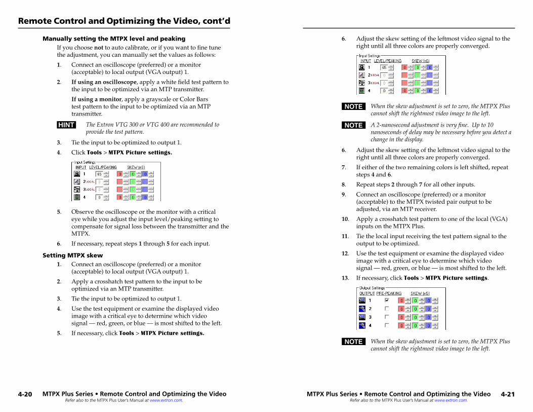
Refer also to the MTPX Plus User’s Manual at www.extron.com.
Refer also to the MTPX Plus User’s Manual at www.extron.com.
Manually setting the MTPX level and peakingIf you choose not to auto calibrate, or if you want to fine tune the adjustment, you can manually set the values as follows:
1. Connect an oscilloscope (preferred) or a monitor (acceptable) to local output (VGA output) 1.
2. If using an oscilloscope, apply a white field test pattern to the input to be optimized via an MTP transmitter.
If using a monitor, apply a grayscale or Color Bars test pattern to the input to be optimized via an MTP transmitter.
H TheExtronVTG300orVTG400arerecommendedtoprovidethetestpattern.
3. Tie the input to be optimized to output 1.
4. Click Tools > MTPX Picture settings.
5. Observe the oscilloscope or the monitor with a critical eye while you adjust the input level/peaking setting to compensate for signal loss between the transmitter and the MTPX.
6. If necessary, repeat steps 1 through 5 for each input.
Setting MTPX skew1. Connect an oscilloscope (preferred) or a monitor
(acceptable) to local output (VGA output) 1.
2. Apply a crosshatch test pattern to the input to be optimized via an MTP transmitter.
3. Tie the input to be optimized to output 1.
4. Use the test equipment or examine the displayed video image with a critical eye to determine which video signal — red, green, or blue — is most shifted to the left.
5. If necessary, click Tools > MTPX Picture settings.
6. Adjust the skew setting of the leftmost video signal to the right until all three colors are properly converged.
N Whentheskewadjustmentissettozero,theMTPXPluscannotshifttherightmostvideoimagetotheleft.
N A2-nanosecondadjustmentisveryfine.Upto10nanosecondsofdelaymaybenecessarybeforeyoudetectachangeinthedisplay.
6. Adjust the skew setting of the leftmost video signal to the right until all three colors are properly converged.
7. If either of the two remaining colors is left shifted, repeat steps 4 and 6.
8. Repeat steps 2 through 7 for all other inputs.
9. Connect an oscilloscope (preferred) or a monitor (acceptable) to the MTPX twisted pair output to be adjusted, via an MTP receiver.
10. Apply a crosshatch test pattern to one of the local (VGA) inputs on the MTPX Plus.
11. Tie the local input receiving the test pattern signal to the output to be optimized.
12. Use the test equipment or examine the displayed video image with a critical eye to determine which video signal — red, green, or blue — is most shifted to the left.
13. If necessary, click Tools > MTPX Picture settings.
N Whentheskewadjustmentissettozero,theMTPXPluscannotshifttherightmostvideoimagetotheleft.
MTPX Pl�us Series • Remote Control� and Optimizing the Video
Remote Control and Optimizing the Video, cont’d
4-20 MTPX Pl�us Series • Remote Control� and Optimizing the Video
4-21
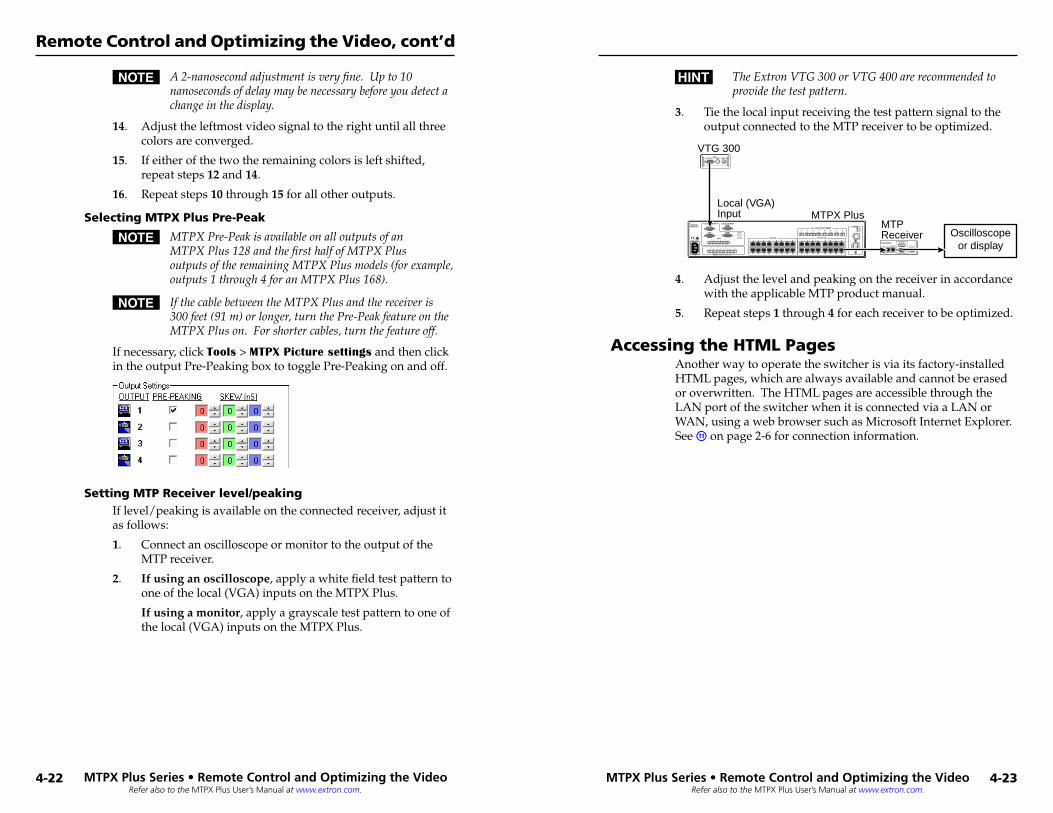
Refer also to the MTPX Plus User’s Manual at www.extron.com.
Refer also to the MTPX Plus User’s Manual at www.extron.com.
N A2-nanosecondadjustmentisveryfine.Upto10nanosecondsofdelaymaybenecessarybeforeyoudetectachangeinthedisplay.
14. Adjust the leftmost video signal to the right until all three colors are converged.
15. If either of the two the remaining colors is left shifted, repeat steps 12 and 14.
16. Repeat steps 10 through 15 for all other outputs.
Selecting MTPX Plus Pre-Peak
N MTPXPre-PeakisavailableonalloutputsofanMTPXPlus128andthefirsthalfofMTPXPlusoutputsoftheremainingMTPXPlusmodels(forexample,outputs1through4foranMTPXPlus168).
N IfthecablebetweentheMTPXPlusandthereceiveris300feet(91m)orlonger,turnthePre-PeakfeatureontheMTPXPluson.Forshortercables,turnthefeatureoff.
If necessary, click Tools > MTPX Picture settings and then click in the output Pre-Peaking box to toggle Pre-Peaking on and off.
Setting MTP Receiver level/peakingIf level/peaking is available on the connected receiver, adjust it as follows:
1. Connect an oscilloscope or monitor to the output of the MTP receiver.
2. If using an oscilloscope, apply a white field test pattern to one of the local (VGA) inputs on the MTPX Plus.
If using a monitor, apply a grayscale test pattern to one of the local (VGA) inputs on the MTPX Plus.
H TheExtronVTG300orVTG400arerecommendedtoprovidethetestpattern.
3. Tie the local input receiving the test pattern signal to the output connected to the MTP receiver to be optimized.
MTPReceiver
VTG 300
Local (VGA)Input MTPX Plus
INPUTBUFFERED
OUTPUT
OUTPUT
POWER12V .5A MAX
MTP RL 15HD A
ON
1 2 3 4 5 6
H S
YN
C +
V S
YN
C +
C S
YN
CS
OG
VID
EO
EN
D U
NIT
1MONO AUDIO
2
MONO AUDIO OUTPUTS
OUTPUTS
RGB
RGB
1
2 3
1
Tx Rx
1L R
1 2AUDIO
3
2L R
3L R
4L R
LOCAL INPUTS LOCAL OUTPUT
RGB
RGB
INPUT SELECT
ON
LOCAL
RJ - 45
1 2 3
RS
-232
/RS
-422
RE
MO
TE
CONTROLRS - 232 OUTPUT INSERT
Tx Rx Tx Rx Tx Rx Tx Rx Tx Rx Tx Rx Tx Rx
INPUTS1 2 3 4 5 6 7 8
9 10 11 12 13 14 15 16
1 2 3 4 5 6 7 8
9 10 11 12 13 14 15 16
1 2 3 4 5 6 7 8
LA
N
RE
SE
T
Oscilloscopeor display
RGB/R-Y,Y,B-Y S-VIDEO COMPOSITEVIDEO
4. Adjust the level and peaking on the receiver in accordance with the applicable MTP product manual.
5. Repeat steps 1 through 4 for each receiver to be optimized.
Accessing the HTML PagesAnother way to operate the switcher is via its factory-installed HTML pages, which are always available and cannot be erased or overwritten. The HTML pages are accessible through the LAN port of the switcher when it is connected via a LAN or WAN, using a web browser such as Microsoft Internet Explorer. See k on page 2-6 for connection information.
MTPX Pl�us Series • Remote Control� and Optimizing the Video
Remote Control and Optimizing the Video, cont’d
4-22 MTPX Pl�us Series • Remote Control� and Optimizing the Video
4-23
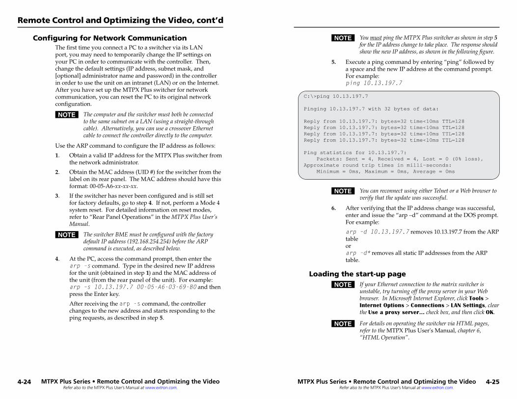
Refer also to the MTPX Plus User’s Manual at www.extron.com.
Refer also to the MTPX Plus User’s Manual at www.extron.com.
Configuring for Network CommunicationThe first time you connect a PC to a switcher via its LAN port, you may need to temporarily change the IP settings on your PC in order to communicate with the controller. Then, change the default settings (IP address, subnet mask, and [optional] administrator name and password) in the controller in order to use the unit on an intranet (LAN) or on the Internet. After you have set up the MTPX Plus switcher for network communication, you can reset the PC to its original network configuration.
N ThecomputerandtheswitchermustbothbeconnectedtothesamesubnetonaLAN(usingastraight-throughcable).Alternatively,youcanuseacrossoverEthernetcabletoconnectthecontrollerdirectlytothecomputer.
Use the ARP command to configure the IP address as follows:
1. Obtain a valid IP address for the MTPX Plus switcher from the network administrator.
2. Obtain the MAC address (UID #) for the switcher from the label on its rear panel. The MAC address should have this format: 00-05-A6-xx-xx-xx.
3. If the switcher has never been configured and is still set for factory defaults, go to step 4. If not, perform a Mode 4 system reset. For detailed information on reset modes, refer to “Rear Panel Operations” in the MTPXPlusUser’sManual.
N TheswitcherBMEmustbeconfiguredwiththefactorydefaultIPaddress(192.168.254.254)beforetheARPcommandisexecuted,asdescribedbelow.
4. At the PC, access the command prompt, then enter the arp –s command. Type in the desired new IP address for the unit (obtained in step 1) and the MAC address of the unit (from the rear panel of the unit). For example: arp –s 10.13.197.7 00-05-A6-03-69-B0 and then press the Enter key.
After receiving the arp -s command, the controller changes to the new address and starts responding to the ping requests, as described in step 5.
N YoumustpingtheMTPXPlusswitcherasshowninstep5fortheIPaddresschangetotakeplace.TheresponseshouldshowthenewIPaddress,asshowninthefollowingfigure.
5. Execute a ping command by entering “ping” followed by a space and the new IP address at the command prompt. For example: ping 10.13.197.7
C:\>ping 10.13.197.7
Pinging 10.13.197.7 with 32 bytes of data:
Reply from 10.13.197.7: bytes=32 time<10ms TTL=128Reply from 10.13.197.7: bytes=32 time<10ms TTL=128Reply from 10.13.197.7: bytes=32 time<10ms TTL=128Reply from 10.13.197.7: bytes=32 time<10ms TTL=128
Ping statistics for 10.13.197.7: Packets: Sent = 4, Received = 4, Lost = 0 (0% loss),Approximate round trip times in milli-seconds: Minimum = 0ms, Maximum = 0ms, Average = 0ms
N YoucanreconnectusingeitherTelnetoraWebbrowsertoverifythattheupdatewassuccessful.
6. After verifying that the IP address change was successful, enter and issue the “arp –d” command at the DOS prompt. For example:
arp –d 10.13.197.7 removes 10.13.197.7 from the ARP table or arp –d* removes all static IP addresses from the ARP table.
Loading the start-up pageN IfyourEthernetconnectiontothematrixswitcheris
unstable,tryturningofftheproxyserverinyourWebbrowser.InMicrosoftInternetExplorer,clickTools>Internet Options>Connections>LAN Settings,cleartheUse a proxy server...checkbox,andthenclickOK.
N FordetailsonoperatingtheswitcherviaHTMLpages,refertotheMTPX Plus User's Manual,chapter6,“HTMLOperation”.
MTPX Pl�us Series • Remote Control� and Optimizing the Video
Remote Control and Optimizing the Video, cont’d
4-24 MTPX Pl�us Series • Remote Control� and Optimizing the Video
4-25
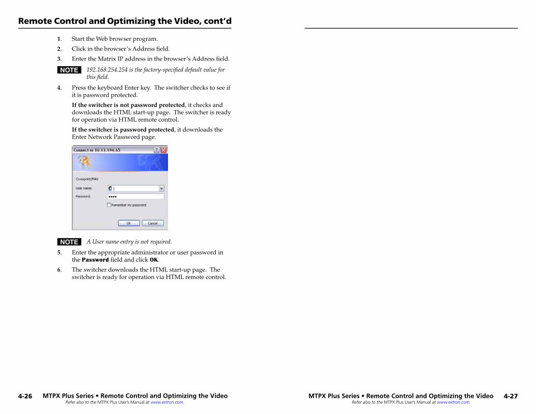
Refer also to the MTPX Plus User’s Manual at www.extron.com.
Refer also to the MTPX Plus User’s Manual at www.extron.com.
1. Start the Web browser program.
2. Click in the browser’s Address field.
3. Enter the Matrix IP address in the browser’s Address field.
N 192.168.254.254isthefactory-specifieddefaultvalueforthisfield.
4. Press the keyboard Enter key. The switcher checks to see if it is password protected.
If the switcher is not password protected, it checks and downloads the HTML start-up page. The switcher is ready for operation via HTML remote control.
If the switcher is password protected, it downloads the Enter Network Password page.
N AUsernameentryisnotrequired.
5. Enter the appropriate administrator or user password in the Password field and click OK.
6. The switcher downloads the HTML start-up page. The switcher is ready for operation via HTML remote control.
MTPX Pl�us Series • Remote Control� and Optimizing the Video
Remote Control and Optimizing the Video, cont’d
4-26 MTPX Pl�us Series • Remote Control� and Optimizing the Video
4-27

Refer also to the MTPX Plus User’s Manual at www.extron.com.
MTPX Pl�us Series • Remote Control� and Optimizing the Video
Remote Control and Optimizing the Video, cont’d
4-28


![Untitled-1 [] · Dipswitch/ Dipswitch/ Dipswitch/ Conmutador DIP/ Dip-Schalter/ Dipswitch Black/ Noir/ Nero/ Negro/ Schwarz/ Zwart INOX/ MINI/ VKP/ Vprox/ LCS/ MTPX Cable Ø6.0(3NoS)](https://img.pdfslide.us/doc/110x75/5ea9acc78bb1ec3469444169/untitled-1-dipswitch-dipswitch-dipswitch-conmutador-dip-dip-schalter-dipswitch.jpg)