Embed Size (px)
Citation preview

EcoSystem® Design and Application Guide

Lutron | 01Technical Support: 1.800.523.9466 – 24 hours/7 days (US/CAN)
EcoSystem®
Energy-saving strategies
60% High-end trim/Tuning 1 (20% lighting) Occupancy or vacancy sensing 2 (15% lighting) Daylight harvesting 3 (15% lighting) Personal dimming control 4 (10% lighting)
Energi Savr Node™ with EcoSystem modulepg. 21
Radio Powr Savr™ wireless daylight sensor pg. 24
NEW Radio Powr Savr wireless occupancy and vacancy sensorpg. 26
NEW Pico® wireless controlspg. 28
Potential lighting energy savings
Sources can be found on pg. 04.
NEW EcoSystem H-Series digital ballastspg. 16
Lutron solutions do more than just control the light in a space. With the right design strategies, they can save substantial amounts of energy, reduce operating costs, and improve productivity.

02 | Lutron www.lutron.com/ecosystem Lutron World Headquarters: 1.610.282.3800 Lutron | 03Technical Support: 1.800.523.9466 – 24 hours/7 days (US/CAN)
The new EcoSystem H-Series ballast is a cost-effective digital ballast option designed to meet the growing need for intelligent energy savings. The H-Series ballast offers superior capability, easy setup, and increased flexibility, see pg. 16.
NEW!
EcoSystem is designed for office spaces, K–12/university classrooms, and patient rooms, where lighting typically accounts for 39% of electricity usage. These applications benefit from EcoSystem’s unparalleled energy savings achieved through the use of personal controls including wallstations and infrared remote control transmitters, and environmental sensors such as daylight and occupancy/vacancy sensors.
In addition to providing energy savings, EcoSystem creates a more flexible workspace in which lighting fixtures with EcoSystem fluorescent ballasts and LED drivers are individually addressed. These ballasts and drivers are programmed, instead of wired, to work individually or as a group, creating flexibility in a space that adjusts to the shifting needs of any building.
Finally, EcoSystem features fewer parts and user-friendly programming reducing lighting system maintenance. Environmental sensors and personal controls integrate wirelessly or connect directly to any ballast, Energi Savr Node™ module, or QS sensor module, eliminating interfaces, power packs, and control devices.
EcoSystem is a lighting control system comprised of digital fluorescent dimming ballasts, LED drivers, controls, and environmental sensors. Working together, these components:
• save up to 60% of lighting electricity usage• increase space flexibility• increase occupant comfort and productivity• reduce maintenance costs
EcoSystem®
1 Energy Information Administration, 2003 Commercial Buildings Energy Consumption Survey, released April 2009. (www.eia.doe.gov/emeu/cbecs/cbecs2003/lighting/lighting1.html)
Annual electricity use in commercial buildings1
Lighting Office Equipment
Other0
5
10
15
20
25
30
35
40
HVAC
18% 15%
60%
39%
28%
Save 60% of lighting energy
Save 10-30% of HVAC energy
Lutron solutions
EcoSystem design and application guide
04 Energy-saving light control strategies 06 Codes and standards08 Foundation for a system 10 How to design a system 12 Wiring overview
Components16 EcoSystem H-Series digital ballasts17 Hi-lume® 3D digital ballasts18 EcoSystem digital ballasts with integral
sensor connections19 EcoSystem digital ballasts20 Hi-lume A-Series LED drivers21 Energi Savr Node with EcoSystem module22 QS sensor module23 Other Energi Savr Node modules
24 Daylight sensors26 Occupancy/Vacancy sensors 28 Pico® wireless controls29 Infrared receivers and remote
control transmitters30 seeTouch® QS wallstations31 EcoSystem wallstations32 QS interfaces33 Programming 34 Expanding the system 36 Concept drawings 42 Emergency system integration43 System hierarchy44 Buy American Act45 Custom ballast factor

04 | Lutron Lutron | 05Technical Support: 1.800.523.9466 – 24 hours/7 days (US/CAN) www.lutron.com/ecosystem Lutron World Headquarters: 1.610.282.3800
Daylight harvesting
Take advantage of available daylight. Adjust electric lighting smoothly, unobtrusively and continuously.
Best applied in areas with large windows or skylights, such as perimeter offices, classrooms, malls, and atriums.
Typical lighting energy savings: 15%3
Potential lighting energy savings when combining all light control strategies: 60%+
Personal dimming control
Provide personal choice and control of light levels to accommodate for different tasks and activities. Permit dimming from multiple locations. Allow the ability to turn lights on and off.
Best applied in areas such as meeting rooms, offices, classrooms, and patient rooms.
Typical lighting energy savings: 10%4
High-end trim/Tuning
Set the maximum light level in a space based on customer or design requirements.
Best applied in daylit spaces such as open office areas, classrooms, and corridors or when retrofitting an existing installation.
Typical lighting energy savings: 20%1
Occupancy/Vacancy sensing
Slowly dim lights to a low level or turn lights off when the space is unoccupied; turn lights on when someone enters.
Best applied in enclosed areas such as meeting rooms, offices, classrooms, and corridors.
Typical lighting energy savings: 15%2
Intelligent lighting control offers a significant energy- saving opportunity
Despite the fact that most lighting is energy-efficient fluorescent, the number-one source of energy consumption in any building is still lighting.
0%
100%
OffOff 0%
100%
7AM Noon 7PM
Ele
ctric
ity U
sage
OffOff7AM Noon 7PM
Ele
ctric
ity U
sageSavings
Savings
Lights on
0%
100%
OffOff7AM Noon 7PM
Ele
ctric
ity U
sage
Sav
ings
Sav
ings
Sav
ings
Lightson
0%
100%
OffOff7AM Noon 7PM
Ele
ctric
ity U
sage
Lights on
Savings
Lights on
0%
100%
OffOff 0%
100%
7AM Noon 7PM
Ele
ctric
ity U
sage
OffOff7AM Noon 7PM
Ele
ctric
ity U
sageSavings
Savings
Lights on
0%
100%
OffOff7AM Noon 7PM
Ele
ctric
ity U
sage
Sav
ings
Sav
ings
Sav
ings
Lightson
0%
100%
OffOff7AM Noon 7PM
Ele
ctric
ity U
sage
Lights on
Savings
Lights on
0%
100%
OffOff 0%
100%
7AM Noon 7PM
Ele
ctric
ity U
sage
OffOff7AM Noon 7PM
Ele
ctric
ity U
sageSavings
Savings
Lights on
0%
100%
OffOff7AM Noon 7PM
Ele
ctric
ity U
sage
Sav
ings
Sav
ings
Sav
ings
Lightson
0%
100%
OffOff7AM Noon 7PM
Ele
ctric
ity U
sage
Lights on
Savings
Lights on
0%
100%
OffOff 0%
100%
7AM Noon 7PM
Ele
ctric
ity U
sage
OffOff7AM Noon 7PM
Ele
ctric
ity U
sageSavings
Savings
Lights on
0%
100%
OffOff7AM Noon 7PM
Ele
ctric
ity U
sage
Sav
ings
Sav
ings
Sav
ings
Lightson
0%
100%
OffOff7AM Noon 7PM
Ele
ctric
ity U
sage
Lights on
Savings
Lights on
Energy-saving light control strategies
1 Newsham, G. R.; Donnelly, C.; Mancini, S.; Marchand, R.G.; Lei, W. Charles, K.E.; Veitch, J.A. (August 13-18, 2008). The effect of ramps in temperature and electric light level on office occupants: a literature review and laboratory experiment. Institute for Research in Construction. Retrieved from http://www.nrc-cnrc.gc.ca/obj/irc/doc/pubs/nrcc41868/nrcc41868.pdf
2 IESNA 2000 Proceedings, Paper #43: An analysis of the energy and cost savings potential of occupancy sensors for commercial lighting systems. ”Occupancy sensor savings range from 17% to 60% depending upon space type and time delay settings.”
3 US Department of Energy. How to Select Lighting Controls for Offices and Public Buildings. Claim: 27% potential savings using daylight harvesting.
4 IESNA 2000 Proceedings, Paper #34: Occupant Use of Manual Lighting Controls in Private Offices. “Giving the occupant manual switching and dimming provided a total of 15% added savings above the 43% achieved by motion sensors.”

06 | Lutron Lutron | 07Technical Support: 1.800.523.9466 – 24 hours/7 days (US/CAN) www.lutron.com/ecosystem Lutron World Headquarters: 1.610.282.3800
Codes and standards
ASHRAE Energy Code 90.1–2010
ASHRAE Energy Code 90.1–2010 is the newest energy standard and is the basis for most state-specific codes as well as the IECC code. The following chart outlines sections of the ASHRAE code most applicable to lighting energy, and identifies the Lutron® lighting control solutions that can help you meet and exceed these codes.
For more specific information on energy codes in your state, visit www.bcap-energy.org.
ASHRAE Section Lighting Control Solution
Automatic Lighting Shut-off (9.4.1.1)
Interior lighting shall be controlled with an automatic control device to shut off building lighting in all spaces (no 5,000 sq. ft. minimum building size)
EcoSystem® with wired or wireless occupancy/vacancy sensors and timeclock integration
Space Control (9.4.1.2)
Multi-level lighting—The controlled lighting in a space shall have at least one control step between 30% and 70% (inclusive) of full-lighting power in addition to all off.
EcoSystem with dimming control; multi-scene control
Each space enclosed by ceiling height partitions shall have at least one control device to independently control the general lighting within the space.
Energi Savr Node™ modules with seeTouch® QS wallstations, EcoSystem wallstations and/or Pico® wireless controls
An occupant sensor or timer switch shall be installed that automatically turns lighting off within 30 minutes of all occupants leaving a space (specific room type are defined within the code).
EcoSystem with occupancy/vacancy sensors, integration with a timeclock, or after hours mode
ASHRAE Section Lighting Control Solution
Automatic Daylighting Controls for Primary Sidelighted Areas (9.4.1.3) and for Toplighting (9.4.1.4)
Sidelighted areas larger than 250 sq. ft. (and/or daylighted areas under skylights larger than 900 sq. ft.) must have a multi-level photocontrol that reduces electric lighting in response to available daylight with at least one control step that is between 50% and 70% of design lighting power and another control step that is no greater than 35% (including off) of design power.
EcoSystem with wired or wireless daylight sensor(s)
Additional Lighting Control (9.4.1.6)
Stairwell lighting—Lighting in enclosed stairwells shall have one or more control devices to automatically reduce lighting power in any one controlled zone by at least 50% within 30 minutes of all occupants leaving that controlled zone.
EcoSystem with wired or wireless occupancy/vacancy sensors
Additional Lighting Power (9.6.2)
Additional lighting power allowances toward Lighting Power Density (LPD) requirements when you use controls that are not already mandated. Controls that give you credits are: Multi-level occupancy/vacancy sensors, dimming, workstation occupancy/vacancy sensors, daylight switching and daylight dimming.
EcoSystem with wired or wireless occupancy/vacancy sensors and/or daylight sensors, dimming ballasts, and personal control

08 | Lutron Lutron | 09Technical Support: 1.800.523.9466 – 24 hours/7 days (US/CAN) www.lutron.com/ecosystem Lutron World Headquarters: 1.610.282.3800
Foundation for a system
EcoSystem® lighting control starts with one simple, but essential building block—the EcoSystem ballast—which replaces the non-dim ballast in a fixture. Depending on the type of room or facility, any combination of environmental sensors or wallstations can be used to control the fixture.
1%
1%
10%
5%
Digital ballast options for 1% dimming
EcoSystem H-Series 1% fluorescent dimming ballasts, pg. 16 Please visit www.lutron.com/hseries for model availability.
Available for:• 4 ft. T8 1, 2 and 3-lamp fixtures (1.0 and 1.17 ballast factor)• 4 ft. T5 and T5HO 1- and 2-lamp fixtures
Hi-lume 3D 1% fluorescent dimming ballasts, pg. 17Please visit www.lutron.com/hilume3D for model availability.
EcoSystem digital ballasts with integral sensor connections, pg. 18Please visit www.lutron.com/ecosystem for model availability.
EcoSystem CFL digital ballasts, pg. 19Please visit www.lutron.com/ecosystem for model availability.
Ballasts
Now the highest performance dimming solution meets any budget.
Additional digital ballast options for 1% dimming
Other digital ballast options
Other digital ballast options
NEW!
10 | Lutron www.lutron.com/ecosystem Lutron World Headquarters: 1.610.282.3800 Lutron | 11Technical Support: 1.800.523.9466 – 24 hours/7 days (US/CAN)
1
2
How to design a system
Before designing a system consider the following to help clarify the scope of the project:
Define your space
The appropriate lighting control solution is defined by the needs of the space. The following steps help to answer key questions and drive you to the ideal lighting control solution.
Step sensor selection
Step control selection
Step accessory devices
Step programming
3
4
5
6
Step ballast and driver selection
A Determine number of fixtures that will be connected to EcoSystemB Determine the fixture type and how the fixtures are driven
– Fluorescent and/or LED – Digital control only and/or digital and 3-wire control
See pgs. 16–20 for all ballast and driver options
Step Energi Savr Node™ selectionA Select main control moduleB Determine if additional lighting fixtures will be controlled
as a switched or 0–10 V zone
See pgs. 21–23 for all module options
A Determine what sensors will be connected to EcoSystem B Choose wireless or wired sensors or a combination
of both technologies
See pgs. 24–27 for all sensor options
Determine the type of wall control required and/or if there are additional points of control needed in the space
See pgs. 28–31 for all control options
Determine integration strategy needed (if any) and timeclock requirements
See pg. 32 for accessory options
Determine device for system programmimg
See pg. 33 for all programming options
TR
IM
O
FF
TR
IM
O
FF

NEW Energi Savr Node™ with EcoSystem® Module, pg. 21• Counts as 1 QS device• Provides 30 Power Draw Units (PDUs)• Can count as 1 – 100 zones• Can count as 1 – 100 areas• Wired sensor connections: (12 total devices) – 4 daylight sensors (maximum) – 4 occupancy sensors (maximum) – 4 IR receivers or wall controls (maximum)• Wi-fi router and Apple iPod touch or iPhone
device required for system programming, pg. 33
www.lutron.com/ecosystem Lutron World Headquarters: 1.610.282.3800 13 | Lutron12 | Lutron Lutron | 14 Lutron | 15Technical Support: 1.800.523.9466 – 24 hours/7 days (US/CAN)
To wired sensor or control
To additional ballasts and drivers
To wired sensor or control
To other QS devices including additional Energi
Savr Node modules
To 3rd party devices
seeTouch® QS Wallstation, pg. 30 • Counts as 1 QS device• Requires 1 PDU
QS Interfaces, pg. 32• Counts as 1 QS device• Consult product specification
for PDU requirement
Type A
NEW EcoSystem H-Series Ballast, pg. 16
Hi-lume® 3D Ballast, pg. 17
Wiring overview
EcoSystem Ballast, pg. 18
Integral sensor connections
Type C
To Distribution
Integral sensor connections
EcoSystem Ballast, pg. 18
Type CType B
To DistributionType E
Type C
To Distribution (120 V, 220/240 V, 277 V)
Type D
On
Meeting
A/V
Clean
Off
NEW Hi-lume® A-Series LED Driver, pg. 20
To Distribution
EcoSystem CFL Ballast, pg. 19
To Distribution
Type B Type B
EcoSystem digital link is Class 1 or Class 2, topology free
Wire gauge key
Type A EcoSystem Digital Link (#16 – #18 AWG Solid, Lutron recommends 2 different colors of wire) Class 1 Standard: C-CBL-216-WH-C1 Class 2 Standard: C-CBL-216-WH-1; Class 2 Plenum Rated: C-PCBL-216-CL-1
Type B Line Voltage (#16 – #18 AWG Solid)
Type C Class 2 Low Voltage (#22 AWG Solid (90˚C) Only) Standard: C-CBL-522S-WH-1; Plenum Rated: C-PCBL-522S-CL-1
Type D Line Voltage (#12 – #14 AWG Solid)
Type E QS Communication Link (4-conductor—GRX-CBL-346S-500 or equivalent cable)
Type F Ethernet
NEW QS Sensor Module, pg. 22 (Required for wireless integration)• Counts as 1 QS device• Requires 3 – 11 PDUs depending
on attached wired sensors• 4 wired sensor connections in total can be used
for daylight sensors, occupancy/vacancy sensors, or IR receivers or wallstations
• Wireless sensor and control limits: (30 total devices) – 10 Radio Powr Savr wireless daylight
sensors (maximum) – 10 Radio Powr Savr wireless occupancy/
vacancy sensors (maximum) – 10 Pico wireless controls (maximum)
System rules and maximums
EcoSystem Digital Link Rules (Type A Wire)• Up to 64 EcoSystem-compatible fluorescent ballasts and/or
LED drivers per EcoSystem digital link • Sensor and control communication limits: – 16 daylight sensors – 32 occupancy sensors – 64 IR receivers or wallstations• A sensor or control counts as a device on the EcoSystem digital
link if it is wired to an EcoSystem ballast on the same link, or is programmed to communicate with a fluorescent ballast or LED driver on the EcoSystem digital link
• EcoSystem-compatible fluorescent ballasts and LED drivers on the EcoSystem digital link do not count as QS devices
General QS Communication Link Rules (Type E Wire)• Maximum of 100 zones• Maximum of 100 areas• Maximum of 100 devices, including Energi Savr Node™
modules, QS sensor modules, seeTouch QS wallstations, and QS interfaces
Wireless components
NEW Radio Powr Savr™ Daylight Sensor, pg. 24
NEW Radio Powr Savr Occupancy/ Vacancy Sensor, pg. 26
NEW Pico® Wireless Control, pg. 28
Ballast accepts Type B wire, other wire types may be pig-tailed on.
To Distribution
To Distribution
Type B
Type EWired components such as wired daylight sensors, wired occupancy/vacancy sensors, infrared receivers, and EcoSystem wallstations can wire directly to the ballasts with integral sensor connections or to either the QS sensor module or the Energi Savr Node with EcoSystem module using Type C wire.
Daylight Sensor, pg. 25
or
Type C Type C
Occupancy/ Vacancy Sensor, pg. 27
Infrared Receiver, pg. 29
Pico® wired control pg. 31
Type C
Type C
Type E
Type AType AType A
Type B
Type A Type A Type A
Ethernet cable
Wifi Router
TR
IM
O
FF
TR
IM
O
FF

16 | Lutron Lutron | 17Technical Support: 1.800.523.9466 – 24 hours/7 days (US/CAN) www.lutron.com/ecosystem Lutron World Headquarters: 1.610.282.3800
T8, T5 and T5HO digital ballast dimensionsL: 18.00" (457 mm)W: 1.18" (30 mm)H: 1.00" (25 mm)Mounting center: 17.70" (450 mm)
T8 and T5 Twin-tube digital ballast dimensionsL: 9.50" (241 mm)W: 2.38" (60 mm)H: 1.00" (25 mm)Mounting center: 8.90" (226 mm)
NEW T8, T5, and T5HO digital ballast dimensions (C case)L: 18.00" (457 mm)W: 1.18" (30 mm)H: 1.00" (25 mm)Mounting center: 17.70" (450 mm)
EcoSystem H-Series digital ballasts
Design statement: Specify EcoSystem H-Series digital ballasts for high-performance 1% dimming. Lighting will be controlled entirely by EcoSystem; sensors communicate to ballasts via an Energi Savr Node™ module.
Hi-lume® 3D digital ballasts
Design statement: Specify Hi-lume 3D digital ballasts to be installed in areas of an EcoSystem lighting control solution that require architectural level dimming. Ballasts also have 3-wire inputs.
NEW!
EcoSystem®
Step ballast and driver selection Step ballast and driver selection1 1
Performance • Universal voltage input allows the ballast to be operated
at 120 V, 220/240 V, or 277 V at 50/60 Hz • 347 V input available for 1- and 2-lamp fixtures • High-performance dimming down to <1% for T8,
1% for T5 and T5HO • Strikes to any light level
Benefits • With models available for T8, T5, and T5HO, use EcoSystem
H-Series throughout any space • Digitally configured zones can be changed without re-wiring • The EcoSystem digital link offers improved flexibility and can
be wired as Class 1 or Class 2 • The low-voltage, 2-conductor EcoSystem digital link installs
as easy as 0–10 V and provides for individual fixture control • Responds to daylight sensors, occupancy/vacancy sensors,
and controls connected to the EcoSystem ballast, Energi Savr Node module, or QS sensor module
Energy • Saves energy as it dims • Helps meet energy codes such as ANSI/ASHRAE/IESNA
standard 90.1-2010, Title 24, and IECC • Custom factory-tuned ballast factors available to help meet
lighting power density requirements
Models For the latest information and model numbers,
visit www.lutron.com/hseries
For wiring overview, see pgs. 12–15 For concept drawings, see pgs. 36–41
Note: For 2 ft. and 3 ft., 1% dimming ballasts use Hi-lume® 3D, see www.lutron.com/hilume3D for more information.
Performance • Universal voltage; operates at 120 V, 220/240 V, and 277 V,
at 50/60 Hz • Smoothly dims from 100% to 0.7% for T8 lamps;
100% to 1% for T5 and T5HO lamps; and 100% to 5% for T5 Twin-tube lamps
• Strikes to any light level
Benefits • Models available for T8, T5HO and T5 Twin-tube; use in
conference rooms, classrooms, and/or patient rooms • Hi-lume 3D ballasts are digitally addressed and configured
to work in zones after installation, which can reduce zone definition and additional design steps
• Responds to daylight sensors, occupancy/vacancy sensors, and controls connected to EcoSystem ballasts, Energi Savr Node modules, or QS sensor modules
Energy • Saves energy as it dims • Helps meet energy codes such as ANSI/ASHRAE/IESNA
standard 90.1-2010, Title 24, and IECC • Custom factory-tuned ballast factors available to help meet
lighting power density requirements
Models For the latest information and model numbers,
visit www.lutron.com/hilume3d
For wiring overview, see pgs. 12–15 For concept drawings, see pgs. 36–41
NEW T8, T5, and T5HO digital ballast dimensions (M case)L: 14.13" (359 mm)W: 1.18" (30 mm)H: 1.00" (25 mm)Mounting center: 13.68" (347 mm)
NEW T8, 3-lamp digital ballast dimensions (G case)L: 9.50" (241 mm)W: 2.38" (60 mm)H: 1.00" (25 mm)Mounting center: 8.90" (226 mm)

18 | Lutron Lutron | 19Technical Support: 1.800.523.9466 – 24 hours/7 days (US/CAN) www.lutron.com/ecosystem Lutron World Headquarters: 1.610.282.3800
EcoSystem®
T4 triple-tube and T4 quad-tube digital ballast dimensionsL: 4.90" (124 mm)W: 3.00" (76 mm)H: 1.00" (25 mm)Mounting center: 4.60" (117 mm)
EcoSystem CFL digital ballasts
Design statement: Specify EcoSystem CFL digital ballasts for dimming performance to 5%. Lighting controls can be a combination of EcoSystem digital and/or 3-wire controls; sensors communicate to ballasts via the Energi Savr Node module.
Step ballast and driver selection1
Performance • Universal voltage; operates at 120 V, 220/240 V, and 277 V,
at 50/60 Hz • Smoothly dims from 100% to 5% for T4 triple-tube and T4 quad-tube • Strikes to any light level
Benefits • Models available for T4 triple-tube and T4 quad-tube;
use throughout an office, school, and/or healthcare building • EcoSystem ballasts are digitally addressed and configured
to work in zones after installation, which can reduce zone definition and additional design steps
• Responds to daylight sensors, occupancy/vacancy sensors, and controls connected to the EcoSystem ballast, Energi Savr Node module, or QS sensor module
Energy • Saves energy as it dims • Helps meet energy codes such as ANSI/ASHRAE/IESNA
standard 90.1-2010, Title 24, and IECC • Custom factory-tuned ballast factors available to help meet
lighting power density requirements
Models For the latest information and model numbers,
visit www.lutron.com/ecosystem
For wiring overview, see pgs. 12–15 For concept drawings, see pgs. 36–41
T8, T5, T5HO, and T5 twin-tube digital ballast dimensionsL: 18.00" (457 mm)W: 1.18" (30 mm)H: 1.00" (25 mm)Mounting center: 17.70" (450 mm)
T8 digital ballast dimensionsL: 9.50" (241 mm)W: 2.38" (60 mm)H: 1.00" (25 mm)Mounting center: 8.90" (226 mm)
EcoSystem digital ballasts with integral sensor connections
Design statement: Specify EcoSystem ballasts with integral sensor connection for dimming performance to 10%. Lighting controls can be a combination of EcoSystem digital and/or 3-wire controls; sensors communicate directly via integral ballast sensor connections or through the Energi Savr Node™ module.
Step ballast and driver selection1
Performance • Universal voltage; operates at 120 V, 220/240 V, and 277 V,
at 50/60 Hz; select models are available in 347 V • Smoothly dims from 100% to 10% for T8, T5, T5HO and T5 twin-tube • Strikes to any light level
Benefits • Models available for T8, T5, T5HO, and T5 twin-tube;
use throughout an office, school, and/or healthcare building • EcoSystem ballasts are digitally addressed and configured
to work in zones after installation, which can reduce zone definition and additional design steps
• Powers and/or responds to one daylight sensor, occupancy/ vacancy sensor, and wallstation or infrared receiver
Energy • Saves energy as it dims • Helps meet energy codes such as ANSI/ASHRAE/IESNA
standard 90.1-2010, Title 24, and IECC • Custom factory-tuned ballast factors available to help meet
lighting power density requirements
Models For the latest information and model numbers,
visit www.lutron.com/ecosystem
For wiring overview, see pgs. 12–15 For concept drawings, see pgs. 36–41

20 | Lutron Lutron | 21Technical Support: 1.800.523.9466 – 24 hours/7 days (US/CAN) www.lutron.com/ecosystem Lutron World Headquarters: 1.610.282.3800
Step Energi Savr Node selection2
Energi Savr Node with EcoSystem module
Design statement: EcoSystem communication starts with an Energi Savr Node module. The Energi Savr Node module digitally links ballasts and powers communications throughout the lighting control system. Specify an Energi Savr Node module for controlling up to 64 or 128 fluorescent ballasts or LED drivers.
Features • Provides individual control of 64 or 128 EcoSystem-compatible
fluorescent ballasts and/or LED drivers • Combines high-end trim, daylight harvesting, occupancy/vacancy
sensing, personal control, and contact closure integration • Connect directly to other Energi Savr Node modules, GRAFIK
Eye® QS units, or Quantum® to expand functionality and control • Sensor information can be shared across multiple EcoSystem
digital links and across multiple Energi Savr Node modules (iPod touch programming application required)
• Programmable contact-closure input can activate scenes, enable/disable after hours mode, or enable/disable loadshed for demand response
• Model also available for integration with shades, see pg. 35
Mounting • Surface mounted • Can be installed in accordance with National Electrical
Code® (NEC®) Article 300.22(c) “Other spaces used for environmental air”
Models QSN-1ECO-S—1 EcoSystem digital link controlling up to 64
EcoSystem-compatible fluorescent ballasts and/or LED drivers QSN-2ECO-S—2 EcoSystem digital links controlling up to 128
EcoSystem-compatible fluorescent ballasts and/or LED drivers QSN-2ECO-PS120—2 EcoSystem digital links controlling
up to 128 EcoSystem-compatible fluorescent ballasts and/or LED drivers and up to 10 Sivoia® QS shade drives
For wiring overview, see pgs. 12–15 For concept drawings, see pgs. 36–41
NEW Energi Savr Node™ with EcoSystem module dimensionsW: 9.25" (243 mm)H: 13.25" (337 mm)D: 3.16" (80 mm)
NEW Energi Savr Node™ with EcoSystem for Shades module See pg. 35
NEW!
EcoSystem®
Hi-lume® A-Series LED drivers
Design statement: Specify Hi-lume A-Series LED drivers for smooth and continuous 1% dimming for virtually any LED light engine, whether it requires constant current or constant voltage.
NEW!
Performance • Constant voltage options from 10 V to 40 V, available in 0.5 V
steps up to 40 watts • Constant current options from 200 mA to 2.1 Amps,
available in 10 mA steps up to 40 watts • Universal voltage; operates at 120 V, 220/240 V and 277 V,
at 50/60 Hz • Immediate light output • Strikes to any light level
Benefits • Service-free lifetime of 50,000 hours • Responds to daylight sensors, occupancy/vacancy
sensors, and controls connected to EcoSystem ballasts, Energi Savr Node™ modules, or QS sensor modules
Energy • Saves energy as it dims • Helps meet energy codes • Contact the LED Control Center of Excellence for details:
1.877.DIM.LED8
Models For the latest information and model numbers,
visit www.lutron.com/HilumeLED For a list of compatible fixtures, visit
www.lutron.com/LEDTool
For wiring overview, see pgs. 12–15 For concept drawings, see pgs. 36–41
NEW Hi-lume A-Series LED compact driver dimensionsL: 4.90" (124 mm)W: 3.00" (76 mm)H: 1.00" (25 mm)Mounting center: 4.60" (117 mm)
NEW Hi-lume A-Series LED stick driver dimensionsL: 14.13" (359 mm)W: 1.18" (30 mm)H: 1.00" (25 mm)Mounting center: 4.60" (117 mm)
Step ballast and driver selection1

22 | Lutron Lutron | 23Technical Support: 1.800.523.9466 – 24 hours/7 days (US/CAN) www.lutron.com/ecosystem Lutron World Headquarters: 1.610.282.3800
NEW Energi Savr Node for 0-10 V dimming dimensionsW: 9.25" (243 mm)H: 13.25" (337 mm)D: 3.16" (80 mm)
Step Energi Savr Node™ selection2
NEW Energi Savr Node™ with Softswitch dimensionsW: 9.25" (243 mm)H: 13.25" (337 mm)D: 3.16" (80 mm)
Other Energi Savr Node modules
Design statement: Specify additional Energi Savr Node modules based on the control type and functionality you need to add to the lighting control system; for example, adding additional switched zones and/or additional 0–10 V dimming zones.
Features • Provide switched and dimming control of other lighting loads • Combines high-end trim, daylight harvesting, occupancy/vacancy
sensing, personal control, and contact closure integration • Easily expand a system by connecting Energi Savr Node
modules directly to other Energi Savr Node modules, GRAFIK Eye® QS units, or Quantum® to expand functionality and control
• Sensor information can be shared across multiple EcoSystem digital links and across multiple Energi Savr Node modules (iPod touch programming application and Energi Savr Node programming interface required)
• Programmable contact-closure input can activate scenes, enable/disable after hours mode, or enable/disable loadshed for demand response
Mounting • Surface mounted • Can be installed in accordance with National Electrical
Code® (NEC®) Article 300.22(c) “Other spaces used for environmental air”
Models QSN-4S16-S—Energi Savr Node with Softswitch for switching
of four 16 A circuits of lighting loads QSN-4T16-S—Energi Savr Node for 0–10 V for switching
and dimming of four 16 A circuits of 0–10 V loads
For wiring overview, see pgs. 12–15 For concept drawings, see pgs. 36–41
NEW!
EcoSystem®
Step Energi Savr Node™ selection2
NEW! QS sensor module
Design statement: Add a QS sensor module to integrate Lutron wireless and wired sensors and controls through the Energi Savr Node module to EcoSystem®-compatible ballasts and Hi-lume® A-Series LED drivers.
NEW QS sensor module dimensionsH: 4.00" (102 mm)W: 4.00" (102 mm)D: 1.20" (30 mm)
Performance • Uses Clear Connect™ RF Technology for communication
with up to 10 Radio Powr Savr occupancy/vacancy sensors, up to 10 Radio Powr Savr daylight sensors, and up to 10 Pico wireless controls
• QS sensor module connects to up to four Lutron wired sensors or controls—occupancy sensors, daylight sensors, EcoSystem infrared (IR) receivers, EcoSystem wallstations, or Pico Wired control (each input is universal)
• QS sensor module integrates Radio Powr Savr wireless sensors and Pico wireless controls
• Also compatible with Energi Savr Node with Softswitch® and Energi Savr Node for 0–10 V modules
• RF Range: 60 ft. (18 m) line of sight, or 30 ft. (9 m) through walls
Benefits • Powered by QS communication link—no line voltage
connections are required
Mounting • Installs on the ceiling, visible from inside the space,
to guarantee wireless range • Option for J-box mount
Models QSM2-4W-C—434 MHz North America (wired and wireless capability)
QSMX-4W-C—wired sensor inputs only QSM2-XW-C—434 MHz North America (wireless capability only)
QSM2-4W-J— 434 MHz North America (wired and wireless capability, J-box mount)
QSM2-XW-J— 434 MHz North America (wireless capability only, J-box mount)
For wiring overview, see pgs. 12–15 For concept drawings, see pgs. 36–41
Required for integration with Radio Powr SavrTM wireless sensors, pgs. 24, 26, and Pico® wireless controls, pg. 28.

24 | Lutron Lutron | 25Technical Support: 1.800.523.9466 – 24 hours/7 days (US/CAN) www.lutron.com/ecosystem Lutron World Headquarters: 1.610.282.3800
EcoSystem®
Step sensor selection3
Radio Powr Savr™ wireless daylight sensors
Design statement: Specify a wireless daylight sensor to dim or switch zones of light in response to daylight. Wireless integration is ideal in most situations and perfect for retrofit applications.
Performance • 10-year battery life • Up to 10 wireless daylight sensors per QS sensor module • Up to 16 total daylight sensors per EcoSystem digital link • Features Lutron’s reliable proportional daylight open loop control • Has a light range (0–10,000 fc) and a photopic response
matches human eye • Designed to give a linear response to changes in viewed light level • One sensor is capable of switching, stepped dimming,
and continuous dimming of multiple zones • RoHS compliant
Benefits • Sensors require no wiring and simple calibration • Multiple ceiling-mount methods available for different
ceiling materials • Pendant-mount bracket available to mount sensor to a light fixture • Front accessible test buttons make setup easy • Sensor information can be shared across multiple EcoSystem
digital links and across multiple Energi Savr Node™ modules (iPod touch programming application required, see pg. 33)
How it works • Daylight sensors detect sunlight and communicate
the sunlight level to the digital ballasts or LED drivers • The daylight sensor is suitable for internal ambient light
levels between 0 and 500 fc
Models LRF2-DCRB-WH—434 MHz daylight sensor
For wiring overview, see pgs. 12–15 For concept drawings, see pgs. 36–41
NEW Radio Powr Savr wireless daylight sensor dimensionsH: 1.60" (41 mm)D: 1.70" (17 mm)
QS sensor module pg. 22
Wireless integration requires:
NEW!
Step sensor selection3
EcoSystem wired daylight sensors
Design statement: Specify a wired daylight sensor to dim or switch multiple zones of light in response to daylight. Select a wired solution for installations where wireless communication is not recommended or approved (i.e. certain government or medical buildings).
Performance • Up to 16 total daylight sensors per EcoSystem digital link • Features Lutron’s reliable proportional daylight open loop control • Has a light range and a photopic response
matches human eye • Designed to give a linear response to changes in viewed light level • One sensor is capable of switching, stepped dimming,
and continuous dimming of multiple zones • RoHS compliant
Benefits • Low profile for mounting on ceiling tiles or fixtures • Class 2 low voltage enables simplified wiring and mounting • Wires directly to the nearest EcoSystem ballast with integral sensor
connections, Energi Savr Node module, or QS sensor module • Sensor information can be shared across multiple EcoSystem
digital links and across multiple Energi Savr Node modules (iPod touch programming application required, see pg. 33)
How it works • EcoSystem daylight sensors detect incoming daylight and
communicate the daylight level to the digital ballasts or LED drivers • The daylight sensor is suitable for internal ambient light
levels between 0 and 500 fc
Models EC-DIR-WH—Daylight sensor with infrared receiver
For wiring overview, see pgs. 12–15 For concept drawings, see pgs. 36–41
Daylight sensor dimensionsH: 0.69" (17 mm)D: 1.18" (30 mm)Stem length: 1.25" (32 mm) Max wire length: 100 ft. (30 m)

26 | Lutron Lutron | 27Technical Support: 1.800.523.9466 – 24 hours/7 days (US/CAN) www.lutron.com/ecosystem Lutron World Headquarters: 1.610.282.3800
EcoSystem®
Step sensor selection3
Ceiling mount occupancy/vacancy sensor dimensionsH: 4.50" (114 mm)W: 4.50" (114 mm)D: 1.40" (38 mm) Max wire length: 100 ft. (30 m)
Wall mount occupancy/vacancy sensor dimensionsH: 3.75" (95 mm)W: 5.50" (140 mm)D: 4.00" (102 mm) Max wire length: 100 ft. (30 m)
Performance • Up to 32 occupancy/vacancy sensors per EcoSystem digital link • Broad range of models for offices to open spaces—
500 sq. ft., 1000 sq. ft., 1600 sq. ft., or 2000 sq. ft. spaces • Wall-mounted and ceiling-mounted modules available • Ultrasonic, infrared, and dual technology models available • “-R” models provide auxiliary dry contact closure for easy integration
with BMS (building management systems) and A/V systems
Benefits • No power pack required since power for the sensor comes directly
from the EcoSystem ballast with integral sensor connection, an Energi Savr Node module, or the QS sensor module
• Sensor information can be shared across multiple EcoSystem digital links and across multiple Energi Savr Node modules (iPod touch programming application required, see pg. 33)
Models Ceiling Mount LOS-CDT-(500,1000)-WH—Dual technology, 180° LOS-CDT-2000-WH—Dual technology, 360° LOS-CDT- (500R,1000R)-WH—Dual technology with relay, 180° LOS-CDT-2000R-WH—Dual technology with relay, 360° Wall Mount LOS-WDT-WH—Dual technology, 110° LOS-WDT-R-WH—Dual technology with relay, 110°
For wiring overview, see pgs. 12–15 For concept drawings, see pgs. 36–41
See www.lutron.com/occsensors for more information
EcoSystem® wired occupancy/vacancy sensors
Design statement: Specify a wired occupancy/vacancy sensor to provide an automatic off for energy savings. Select a wired solution for installations where wireless communication is not recommended or approved (i.e. certain government or medical buildings).
Step sensor selection3
NEW Radio Powr Savr wireless ceiling mount occupancy/ vacancy sensor dimensionsW: 4.00" (102 mm)H: 4.00" (102 mm)D: 1.30" (33 mm)
NEW Radio Powr Savr wireless wall/hall mount occupancy/vacancy sensor dimensionsW: 6.12" (156 mm)H: 1.62" (41 mm)D: 2.31" (59 mm)
Performance • 10-year battery life design • Up to 10 wireless occupancy/vacancy sensors per QS sensor module • Up to 32 occupancy/vacancy sensors per EcoSystem digital link • Passive infrared motion detection with exclusive Lutron XCT™
Technology for fine motion detection • Vacancy model available to meet CA Title 24 requirements • Wall-mount and ceiling-mount options available • Combine with PowPak CCO module for easy integration with BMS
and A/V systems
Benefits • Sensors require no wiring • Sensors have simple test modes to verify ideal locations
during installation using front-accessible buttons • Multiple ceiling-mount methods available for different ceiling materials • Sensor information can be shared across multiple EcoSystem
digital links and across multiple Energi Savr Node™ modules (iPod touch programming application required, see pg. 33)
Models Ceiling Mount LRF2-OCR2B-P-WH—434 MHz occupancy/vacancy sensor LRF2-VCR2B-P-WH—434 MHz vacancy sensor Wall Mount LRF2-OWLB-P-WH—434 MHz occupancy/vacancy sensor LRF2-VWLB-P-WH—434 MHz vacancy sensor Corner Mount LRF2-OKLB-P-WH—434 MHz occupancy/vacancy sensor LRF2-VKLB-P-WH—434 MHz vacancy sensor Hall Mount LRF2-OHLB-P-WH—434 MHz occupancy/vacancy sensor LRF2-VHLB-P-WH—434 MHz vacancy sensor
See www.lutron.com/RPS for more information
Radio Powr Savr™ wireless occupancy/ vacancy sensors
Design statement: Specify a wireless occupancy/vacancy or vacancy only sensor to provide an automatic off for energy savings. Wireless integration is ideal in most situations and perfect for retrofit applications.
NEW!
QS sensor module pg. 22
Wireless integration requires:

28 | Lutron Lutron | 29Technical Support: 1.800.523.9466 – 24 hours/7 days (US/CAN) www.lutron.com/ecosystem Lutron World Headquarters: 1.610.282.3800
Step control selection Step control selection4 4
EcoSystem®
NEW! Pico® wireless control
Design statement: Use Pico wireless lighting controls to control lights or shades wirelessly within a space with the touch of a button.
Performance • Communicates with the QS sensor module via radio frequency
(RF) using Clear Connect™ RF Technology • Up to 10 Pico wireless controls per QS sensor module • Unique serial number prevents interference between systems • Battery powered (5-year battery life)—requires no new wiring
Benefits • Flexible device that allows the user to control lights or shades
by wirelessly communicating with the QS sensor module • Can function as a tabletop control on a pedestal, a lightweight
handheld remote, or it can be wall-mounted with or without a Lutron Claro® wallplate
• Available in 2- and 3-button configurations with options for preset and raise/lower buttons
Models Pico wireless controls MRF2-3BRL-L-XX—3 buttons with raise/lower MRF2-3B-L-XX—3 buttons with preset button MRF2-3B-L-XX-E01—3 buttons with Welcome button MRF2-2BRL-L-XX—2 buttons with raise/lower MRF2-2B-L-XX—2 buttons Pedestals L-PED1-XX—Single pedestal L-PED2-XX—Double pedestal L-PED3-XX—3-gang pedestal L-PED4-XX—4-gang pedestal Wallplates CW-1-XX—1-gang wallplate (gloss/stainless steel) CW-2-XX—2-gang wallplate (gloss/stainless steel) CW-3-XX—3-gang wallplate (gloss/stainless steel) PICO-FP-ADAPT—Pico wireless control faceplate adapter
XX in the model number represents color/finish code. Please see www.lutron.com for color choices.
Pico wireless control dimensionsH: 2.60" (66 mm)H: 1.28" (33 mm)D: 0.33" (8 mm)
EcoSystem® wired infrared receiver and remote control transmitter
Design statement: Add an EcoSystem infrared receiver with an infrared remote control transmitter to provide personal light control to any fixture on the EcoSystem digital link.
Performance • Allows personalized light level selection from maximum
to minimum light levels • Can control multiple zones or areas • Integral LED indicates signal reception • Up to 64 infrared receivers (one per ballast) may be used per
EcoSystem digital link
Benefits • Low profile for mounting on ceiling tiles or fixtures • Class 2 low voltage enables simplified wiring and mounting • Wires directly to the nearest EcoSystem ballast with integral sensor
connections, Energi Savr Node™ module, or QS sensor module
Models EC-IR-WH—Infrared receiver C-FLRC-WH—Infrared remote control transmitter RCTH-GR—Remote control holster/tether
For wiring overview, see pgs. 12–15 For concept drawings, see pgs. 36–41Infrared remote
control transmitter dimensionsW: 1.51" (38 mm)H: 4.63" (118 mm)D: 0.55" (14 mm)
Other control mounting styles
Infrared receiver dimensionsH: 0.69" (17 mm)D: 1.18" (30 mm)Stem length: 1.25" (32 mm) Max wire length: 100 ft. (30 m)
QS sensor module pg. 22
Wireless integration requires:
30 | Lutron Lutron | 31Technical Support: 1.800.523.9466 – 24 hours/7 days (US/CAN) www.lutron.com/ecosystem Lutron World Headquarters: 1.610.282.3800
EcoSystem®
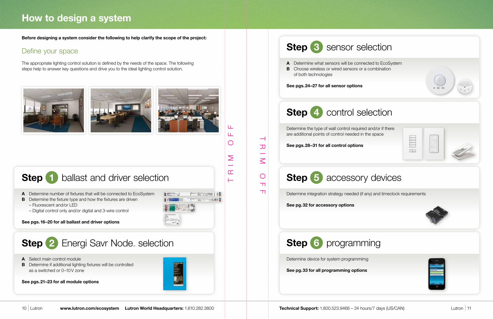
Step control selection4
seeTouch® QS wallstations
Design statement: Specify seeTouch QS wallstations where needed for full-range dimming control with engraved buttons.
Performance • Buttons are backlit and can be engraved to provide intuitive
control of the space • Recall scenes to adjust lighting for different activities • Control individual zones of light to set the perfect light for any task • Control up to 100 zones of lighting from up to 99 wallstations
Benefits • Class 2 low voltage QS communication link simplifies
wiring and mounting • Wallstations are powered directly from the QS communication link
Models QSWS2-1B*—1-button wallstation QSWS2-3B*—3-button wallstation QSWS2-5B*—5-button wallstation QSWS2-7B*—7-button wallstation QSWS2-2BRL*—2-button wallstation with raise/lower QSWS2-3BRL*—3-button wallstation with raise/lower QSWS2-5BRL*—5-button wallstation with raise/lower QSWS2-2BRLIR*—2-button wallstation with raise/lower
and IR receiver QSWS2-3BRLIR*—3-button wallstation with raise/lower
and IR receiver QSWS2-5BRLIR*—5-button wallstation with raise/lower
and IR receiver QSWS2-1RLD*—dual wallstation with 3-button and 2-button
with raise/lower QSWS2-2RLD*—dual 2-button wallstation with raise/lower QSWS2-3BD*—dual 3-button wallstation * Consult seeTouch QS specification submittal sheet for information
on specifying insert style, engraving, and color.
For wiring overview, see pgs. 12–15 For concept drawings, see pgs. 36–41
seeTouch QS wallstation dimensionsW: 2.75" (70 mm)H: 4.56" (116 mm)D: 1.25" (32 mm) Max wire length: 100 ft. (30 m)
On
Meeting
A/V
Clean
Off
Pico® wired control
Design statement: Add a Pico wired control wherever needed for intuitive lighting control.
Performance • Provides control for Lutron® products incorporating wired IR
input including Energi Savr Node units, QS Sensor Modules, and EcoSystem® ballasts or ballast modules, allowing users to:
- Turn an individual fixture or group of fixtures on and off - Raise and lower light levels (PX-2BRL-GZZ and PX-3BRL-GZZ) - Recall favorite light levels (PX-3B-GZZ and PX-3BRL-GZZ)
Benefits • IEC PELV/NEC® Class 2 • Mounts easily in any single-gang wallbox 2.5 in (64 mm)
deep minimum (not included) • Fits any designer Claro® opening faceplates • Low-cost wall control for many applications
Models PX-3BRL-GZZ-I01 — 3 buttons with raise/lower PX-3B-GZZ-I01 — 3 buttons with preset button PX-2BRL-GZZ-I01 — 2 buttons with raise/lower PX-2B-GZZ-I01 — 2 buttons
* ZZ in the model number represents color code
For wiring overview, see pgs. 10–11 For concept drawings, see pgs. 26–31
Pico wired control dimensions (with Claro® faceplate, sold separately)W: 2.94" (75 mm) H: 4.69" (119 mm)D: 1.98" (50 mm) Max wire length: 150ft. (45 m)
Step control selection4
NEW!

Lutron | 33Technical Support: 1.800.523.9466 – 24 hours/7 days (US/CAN)32 | Lutron www.lutron.com/ecosystem Lutron World Headquarters: 1.610.282.3800
EcoSystem®
QS interfaces and QS timeclock
Design statement: Specify QS interfaces to integrate third-party devices through RS-232/Ethernet and/or contact closures. Specify QS timeclock device to provide automatic control of lights and shades.
Performance • Each QS interface and QS timeclock counts as 1 QS device;
QS communication link system limit is 100 QS devices • RS-232/Ethernet interface uses standard 9-pin female
serial connector or RJ45 connector • Contact closure interface provides five inputs and five
dry contact closure outputs • QS timeclock provides an astronomical timeclock with up
to 25 events per day for 7 days and a holiday
Benefits • Integrate with third-party devices and controls via RS-232/Ethernet
or contact-closure inputs • Sweep lights to low levels or off through RS-232/Ethernet, contact closure commands from third-party controls, or timeclock events • Add third-party touchscreen control using RS-232/Ethernet
commands • Deliver code compliant automatic light shut-off to meet ASHRAE
90.1-2010
Models QSE-CI-NWK-E—RS-232/Ethernet control interface QSE-IO—Contact closure input/output interface QSGR-TC-3S-WH-CPN5825—QS timeclock for lights and shades
For wiring overview, see pgs. 12–15 For concept drawings, see pgs. 36–41
For more information on mounting options and installation, please visit www.lutron.com/TechnicalDocumentLibrary
QS RS-232/Ethernet interface dimensionsW: 4.26" (108 mm)H: 5.26" (134 mm)D: 1.06" (27 mm)
QS contact closure interface dimensionsW: 4.26" (108 mm)H: 5.26" (134 mm)D: 1.06" (27 mm)
Step accessory devices5 Step programming6
Programming application for Apple iPhone or iPod touch digital devices
Design statement: Use the Energi Savr Node™ programming application to set up, fine-tune, and maintain the lighting control system.
The Energi Savr Node programming application for Apple iPod or iPhone touch mobile digital devices is the key to an intelligent light and shade control system.
• Adjust ballasts to the needs of any space• Define light level• Adjust sensor and control preferences
NEW System Backup The iPod application can be used to save all configuration settings in
the system. In the event that an Energi Savr Node module is replaced, all system settings and configuration can be automatically restored.
Energi Savr Node Programming Interface The QSE-CI-AP-D is a programming interface for Energi Savr Node
modules that provides the capability to program the lighting control system with an intuitive application for Apple iPhone or iPod touch devices. This required component allows for Ethernet inputs for programming with an Apple iPhone or iPod touch.
Features• Program all Energi Savr Node modules connected to the same
QS communication link• Programming interface installs via surface mount or DIN-rail
Energi Savr Node Wireless Setup Kit (optional—US only) The kit allows users to quickly connect to the system, set up the
desired configuration, and make changes as needed. Features• Plug & Play - fully preconfigured and preloaded with Lutron software• Programs all Energi Savr Node modules• Kit includes an Apple iPod touch and wireless router Note: Use of the Energi Savr Node Wireless Setup Kit is optional. Any
Apple iPod touch and wireless router may be used to setup an Energi Savr Node system
Apple and iPod are registered trademarks and iPhone is a trademark of Apple, Inc., registered in the U.S. and other countries.
NEW!
QS timeclockW: 9.37" (239 mm)H: 4.69" (119 mm)D: 2.37" (61 mm)
34 | Lutron Lutron | 35Technical Support: 1.800.523.9466 – 24 hours/7 days (US/CAN) www.lutron.com/ecosystem Lutron World Headquarters: 1.610.282.3800
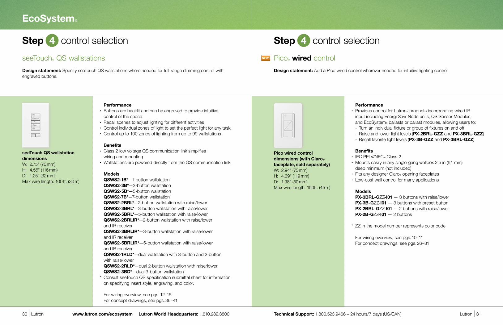
Expanding the system
GRAFIK Eye® QS Wireless with EcoSystem
• Preset light and shade control that allows you to adjust the total light level for any task or activity, while saving energy
• Create lighting effects by assigning fluorescent lights to 6, 8, or 16 zones
• Combines EcoSystem light control, Sivoia® QS wired and wireless shades, and timeclock
• Integrates EcoSystem to touchscreens and other systems via RS-232/Ethernet interfaces and input/output devices
For more information, visit www.lutron.com/grafikeyeqs
GRAFIK Eye QS Wireless with EcoSystem
Quantum Total Light Management• Create an energy-efficient environment by enabling a centralized
management, monitoring, and light and shade control system• Reduce cooling loads by dimming lights and controlling shades
to block solar heat gain• Increase operating efficiency – system automatically reports
lamp failures and monitors lamp hours to manage and reduce maintenance
• Reconfigure lighting and shading zones without costly rewiring
For more information, visit www.lutron.com/quantumQ-Admin™ software
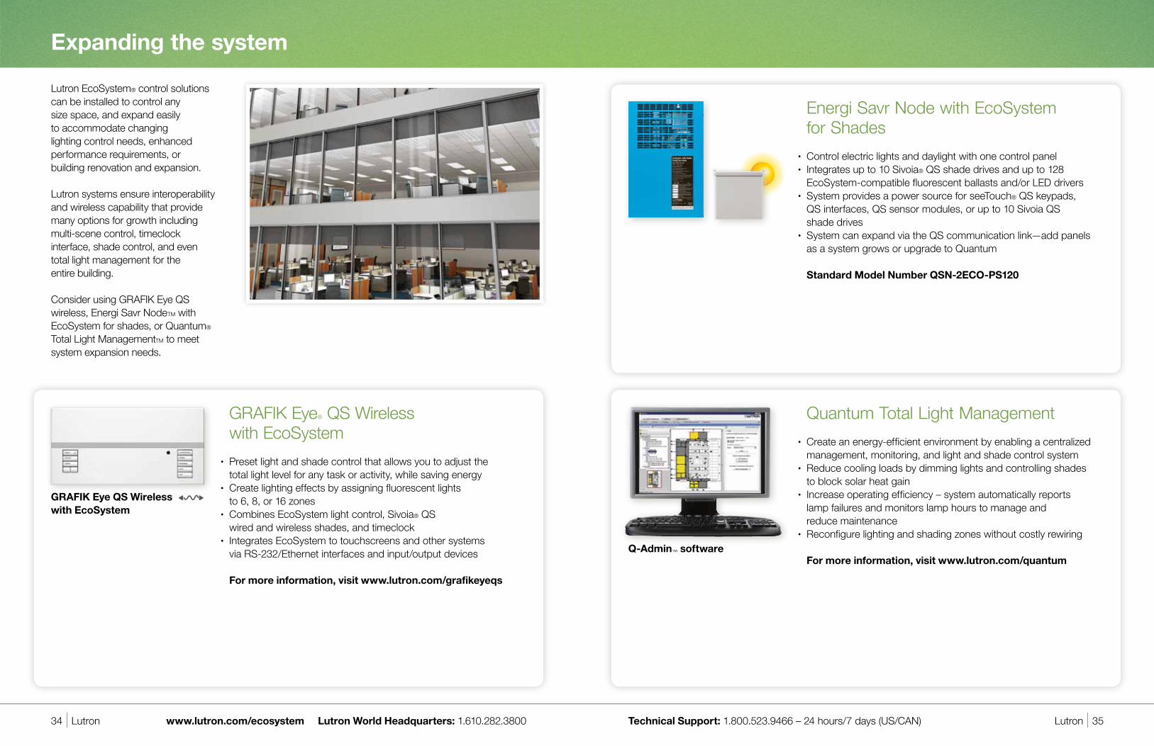
Energi Savr Node with EcoSystem for Shades• Control electric lights and daylight with one control panel • Integrates up to 10 Sivoia® QS shade drives and up to 128
EcoSystem-compatible fluorescent ballasts and/or LED drivers• System provides a power source for seeTouch® QS keypads,
QS interfaces, QS sensor modules, or up to 10 Sivoia QS shade drives
• System can expand via the QS communication link—add panels as a system grows or upgrade to Quantum
Standard Model Number QSN-2ECO-PS120
Lutron EcoSystem® control solutions can be installed to control any size space, and expand easily to accommodate changing lighting control needs, enhanced performance requirements, or building renovation and expansion.
Lutron systems ensure interoperability and wireless capability that provide many options for growth including multi-scene control, timeclock interface, shade control, and even total light management for the entire building.
Consider using GRAFIK Eye QS wireless, Energi Savr NodeTM with EcoSystem for shades, or Quantum® Total Light ManagementTM to meet system expansion needs.

36 | Lutron Lutron | 37Technical Support: 1.800.523.9466 – 24 hours/7 days (US/CAN) www.lutron.com/ecosystem Lutron World Headquarters: 1.610.282.3800
EcoSystem daylight sensor
EcoSystem occupancy/ vacancy sensor
seeTouch® QS wallstation
wW
indo
wWW
indo
w
Window
QS Communication Link
EcoSystem Digital Link
Low Voltage Wiring
Win
dow
Win
dow
Window
QS Communication Link
EcoSystem Digital Link
Use Energi Savr Node with EcoSystem to control all the fluorescent lights in a private or open office—wired option
Design statement: EcoSystem ballasts and wallstation controls enable individual fixture control, daylight harvesting, and/or occupancy/vacancy sensing throughout the office space. Easily reprogram lighting zones if the space is reconfigured or if the employee needs change.
Use Energi Savr Node™ with EcoSystem® to control all the fluorescent lights in a private or open office—wireless option
Design statement: EcoSystem ballasts and wireless controls (can be wall-mounted or personal control) enable individual fixture control, daylight harvesting, and/or occupancy/vacancy sensing throughout the office space. Easily reprogram lighting zones if the space is reconfigured or if the employee needs change.
Radio Powr Savr™ wireless daylight sensor
NEW Radio Powr Savr wireless occupancy/ vacancy sensor
NEW Pico® wireless control (wall-mounted)
NEW EcoSystem H-Series digital ballast
NEW EcoSystem H-Series digital ballast
QS sensor module QS sensor module
Energi Savr Node with EcoSystem module
Energi Savr Node with EcoSystem module
Concept drawings
On
Meeting
A/V
Clean
Off

38 | Lutron Lutron | 39Technical Support: 1.800.523.9466 – 24 hours/7 days (US/CAN) www.lutron.com/ecosystem Lutron World Headquarters: 1.610.282.3800
Use Energi Savr Node™ with EcoSystem® to control lighting in traditional classroom spaces
Design statement: In classrooms, EcoSystem ballasts provide individual fixture control, daylight harvesting, and occupancy/vacancy sensing to save energy, save money, and create a more productive teaching and learning environment.
EcoSystem Digital Link
QS
Com
mun
icat
ion
Link
Use Energi Savr Node with EcoSystem to control lights in university lecture halls
Design statement: Control both fluorescent and LED fixtures within the space, and take advantage of the ability to integrate A/V and shade control (wired or wireless). Automatic controls like occupancy and daylight sensors ensure energy savings.
Window Window Window
Whiteboard
Whiteboard
Whiteboard
QS Communication Link
EcoSystem Digital Link
NEW Pico wireless control
NEW EcoSystem H-Series digital ballast
QS RS-232/Ethernet Interface
To A/V Equipment by Others
NEW Hi-lume® A-Series LED Driver
Concept drawings
Radio Powr Savr™ wireless daylight sensor
NEW Radio Powr Savr wireless occupancy/ vacancy sensor
NEW Radio Powr Savr wireless occupancy/ vacancy sensor
NEW Pico® wireless control (wall-mounted)
NEW EcoSystem H-Series digital ballast
QS sensor module seeTouch® QS wallstation
On
Lecture
A/V
Clean
Off
Energi Savr Node with EcoSystem module Energi Savr Node with
EcoSystem module
QS sensor module

40 | Lutron Lutron | 41Technical Support: 1.800.523.9466 – 24 hours/7 days (US/CAN) www.lutron.com/ecosystem Lutron World Headquarters: 1.610.282.3800
Concept drawings
window
restroom
restroom
window
win
dow
window
Use Energi Savr Node™ with EcoSystem® and Energi Savr Node with Softswitch® modules to control lights on an entire office floor
Design statement: Interoperability and seamless communication between EcoSystem and Softswitch Energi Savr Node modules enables control of all the lights in the space. Connected by the EcoSystem digital link—sensors, ballasts, and controls work together to provide an integrated lighting control solution.
NEW Energi Savr Node with Softswitch module
Controlling all interior lighting of the space allowing for switching as well as occupancy/vacancy sensing, and personal control.
QS Communication Link
Energi Savr Node with EcoSystem module
Energi Savr Node with Softswitch module
Energi Savr Node with Softswitch module
Radio Powr Savr™ wireless daylight sensor
NEW Radio Powr Savr wireless occupancy/ vacancy sensor
NEW Pico® wireless control (wall-mounted)
QS sensor module
NEW EcoSystem H-Series digital ballast
Ballasts connected by EcoSystem digital link
Energi Savr Node with EcoSystem module
NEW Energi Savr Node with EcoSystem module
Controlling all EcoSystem H-Series digital ballasts along the perimeter of the space allowing for full range dimming as well as daylight harvesting, occupancy/vacancy sensing, and personal control.
42 | Lutron Lutron | 43Technical Support: 1.800.523.9466 – 24 hours/7 days (US/CAN) www.lutron.com/ecosystem Lutron World Headquarters: 1.610.282.3800 42 | Lutron www.lutron.com/ecosystem Lutron World Headquarters: 1.610.282.3800
System functionality
Use emergency battery backup ballasts within an EcoSystem-controlled fixture.
• In this case the fixture operates under EcoSystem control when normal power is present • With loss of normal power the emergency battery backup ballast drives the lamp(s)
Power EcoSystem ballasts via emergency/essential power and power the Energi Savr Node module from normal power.
• Loss of normal power causes the EcoSystem digital link to turn off • This signals emergency-powered EcoSystem or EcoSystem-compatible ballasts and drivers to operate at
their emergency levels (100% by default)
Note: • The loss of any phase of normal power results in the emergency mode being activated • Ballasts will operate at their emergency light level until the fault is cleared
Multi-phase lighting system or UL924 compliance The following design consideration should be met to achieve this performance: 1. Power emergency fixtures with EcoSystem ballasts or LED drivers via emergency/essential power. 2. Power the Energi Savr Node module and 24 V DC power pack via emergency/essential power. 3. Install and connect LUT-ELI-3PH to the EcoSystem Energi Savr Node module via installation instructions. For more information please see Lutron Application Note 140 at www.lutron.com.
Emergency system integration
Design statement: Energi Savr Node™ modules offer several options for easily integrating emergency lighting control into applications. Choose battery backup within the EcoSystem® fixture, or power EcoSystem ballasts via emergency power.
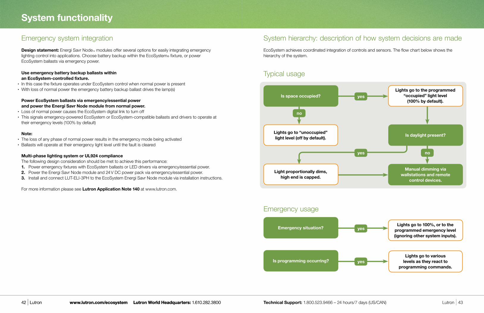
System hierarchy: description of how system decisions are made
EcoSystem achieves coordinated integration of controls and sensors. The flow chart below shows the hierarchy of the system.
Is programming occurring?
yes
yes
Emergency situation?
Lights go to various levels as they react to
programming commands.
Lights go to 100%, or to the programmed emergency level (ignoring other system inputs).
no
yes
yes
Is daylight present?
Is space occupied?
Light proportionally dims, high end is capped.
no
Typical usage
Lights go to the programmed “occupied” light level
(100% by default).
Lights go to “unoccupied” light level (off by default).
Manual dimming via wallstations and remote
control devices.
Emergency usage

44 | Lutron Lutron | 45Technical Support: 1.800.523.9466 – 24 hours/7 days (US/CAN) www.lutron.com/ecosystem Lutron World Headquarters: 1.610.282.3800
NEW Ballast selection tool with custom ballast factor
EcoSystem®
Energy-saving, Buy American-compliant light control solutions
Buy American Act Lutron makes it easy for you to comply with the Buy American Act and the Buy American provisions
in the American Recovery and Reinvestment Act (ARRA). We offer hundreds of light control products that are manufactured in the United States. Contact your authorized Lutron distributor for details. www.Lutron.com/BAA
Targeted to both new and retrofit markets, Lutron ballasts and controls install easily into new construction or existing spaces. Lutron has offered solutions manufactured in the United States since our first product introduction in 1961. With the expansion of our ballast lines, we offer a complete lighting control system for virtually any project requiring products manufactured in the United States.
LEED is a registered trademark of the United States Green Building Council.
Digital fluorescent dimming ballasts manufactured in the United States for your energy-saving needs.
Generate part numbers, confirm ballast performance specs (input power, system lumens, ballast factor) and select the proper ballast by utilizing the Custom Ballast Factor (CBF) option on the Lutron Ballast Selection Tool. CBF is the percentage of light output for a given lamp-ballast combination, and Lutron enables our customers to order reduced ballast factors and achieve greater energy savings, meet lumen/ft” specifications, and/or qualify for the highest levels of LEED. Custom Ballast Factor
• Lutron’s custom ballast factor program offers ballasts with factors ranging from Lutron’s standard offering down to a 0.50 ballast factor
• Each ballast with a custom ballast factor is UL listed and marked with lower input power • Ballasts with a custom ballast factor have a unique model number for easy reorder and replacement• Longer shipping lead times apply
For more information or to order ballasts with custom ballast factors contact your local Lutron sales representative or visit www.lutron.com/BallastTool

.2 in. space on all sides
www.lutron.comWorld Headquarters 1.610.282.3800Technical Support Center 1.800.523.9466 (Available 24/7)Customer Service/Quotes 1.888.LUTRON1 (1.888.588.7661)
© 09/2011 Lutron Electronics Co., Inc.P/N 367-1533 REV C