Embed Size (px)
Citation preview

DESCRIPTION OF CONTROL

GENERALThe Nuaire unit contains the following controllable items:
l Inlet Damper (if fitted).
l Exhaust Damper (if fitted).
l Heat Recovery and Bypass Damper.
l Frost Heating coil (if fitted).
l Heating Coil.
l Cooling Coil.
l Supply Fan Speed.
l Extract Fan Speed.
All setpoints are user adjustable.
Heating and Cooling can be manually overridden off.
Software designed for ETHERNET connection to main head end.
RUN DEMANDSThe unit can be enabled in one of two ways, selectable via software switch:
l Local Control.
l Remotely enabled.
Should the emergency input not be healthy, the unit is disabled immediately.
LOCAL CONTROL (IQVIEW4 / SDU)Under local control the unit will be enabled in the following conditions:
l Optimum Start Stop (OSS).
l Override Extension.
l Fabric Protection
l Night Cooling mode.
l Boost Mode.
In OSS the unit is enabled so that the space temperature should reach setpoint by the users defined time
profile (Occupation times). The unit will continue to run until the end of these times.
Override Extension is selectable via software switch and will enable the plant as if in OSS for an hour.
In Fabric Protection should the space temperature drop below the Fabric Protection setpoint then the unit is
also enabled until it rises 1O C above this setpoint.
029 2085 82002
DESCRIPTION OF CONTROL -NUAIRE UNIT CONTROLLED BY AN ECOSMART2 CONTROLLER
ECOSMART2 - ENHANCED DEMAND CONTROLLED VENTILATION
A comprehensive unit
control specification -
factory fitted and tested
to provide guaranteed
operation from a
single supplier – one who
will take responsibility.
Night Cooling mode is initiated when the following conditions are met:
l Average inlet temperature between 1pm and 6pm above space heating setpoint.
l Average daytime space temperature above the space cooling setpoint.
l The intake temperature is at least 2O C less than the space.
l The space temperature is above the heating setpoint.
l The inlet temperature is above the low limit supply setpoint.
l Outside of OSS times.
Boost Mode is selectable via software switch and will run the unit at maximum heating (with high limit trim)
for 1 hour or until the space temperature is 3O C above the heating setpoint.
REMOTE CONTROLRun demands sent from remote controllers via inter controller communications.
Boost mode and Override Extension are still available.
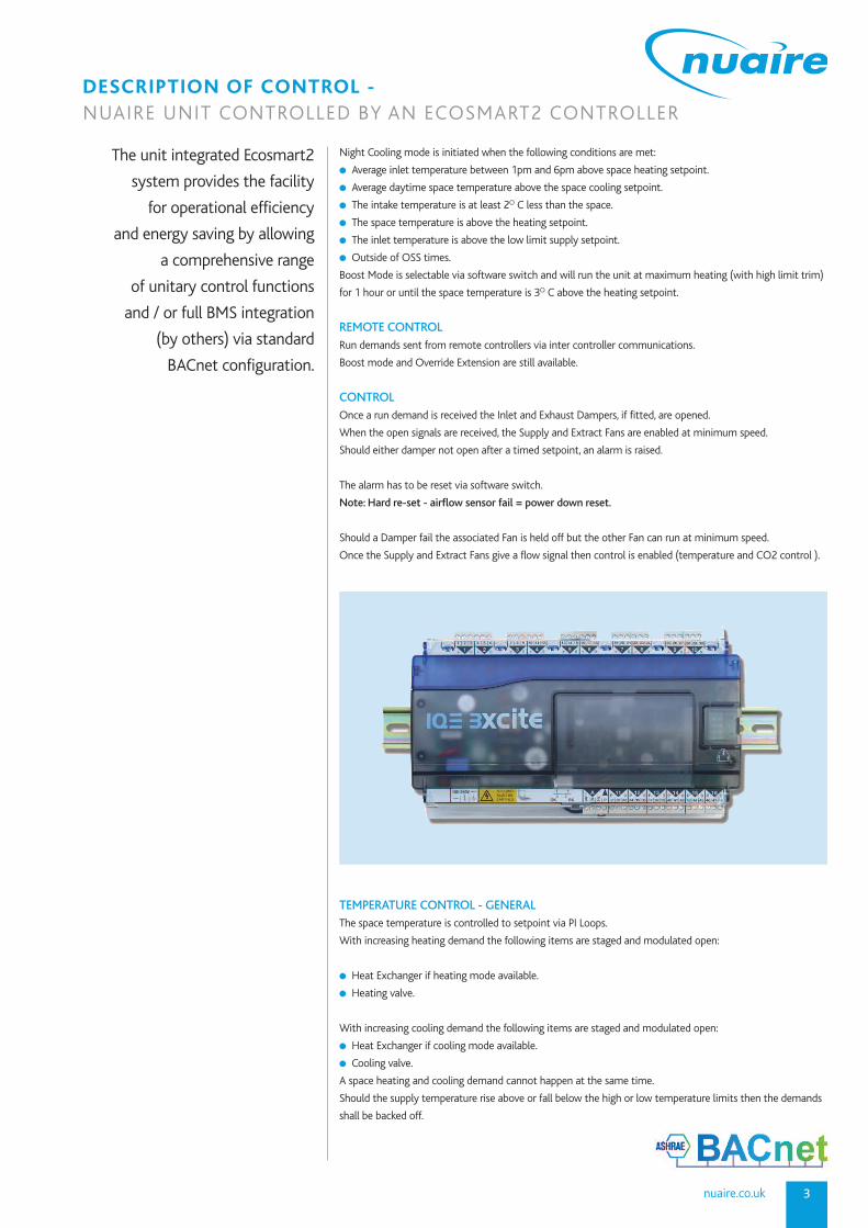
CONTROLOnce a run demand is received the Inlet and Exhaust Dampers, if fitted, are opened.
When the open signals are received, the Supply and Extract Fans are enabled at minimum speed.
Should either damper not open after a timed setpoint, an alarm is raised.
The alarm has to be reset via software switch.
Note: Hard re-set - airflow sensor fail = power down reset.
Should a Damper fail the associated Fan is held off but the other Fan can run at minimum speed.
Once the Supply and Extract Fans give a flow signal then control is enabled (temperature and CO2 control ).
TEMPERATURE CONTROL - GENERALThe space temperature is controlled to setpoint via PI Loops.
With increasing heating demand the following items are staged and modulated open:
l Heat Exchanger if heating mode available.
l Heating valve.
With increasing cooling demand the following items are staged and modulated open:
l Heat Exchanger if cooling mode available.
l Cooling valve.
A space heating and cooling demand cannot happen at the same time.
Should the supply temperature rise above or fall below the high or low temperature limits then the demands
shall be backed off.
3nuaire.co.uk
DESCRIPTION OF CONTROL -NUAIRE UNIT CONTROLLED BY AN ECOSMART2 CONTROLLER
The unit integrated Ecosmart2
system provides the facility
for operational efficiency
and energy saving by allowing
a comprehensive range
of unitary control functions
and / or full BMS integration
(by others) via standard
BACnet configuration.

029 2085 82004
DESCRIPTION OF CONTROL -NUAIRE UNIT CONTROLLED BY AN ECOSMART2 CONTROLLER
FROST VALVEIf fitted this is controlled whenever the unit is enabled to maintain the off coil temperature to setpoint by
modulation of the valve.
The control is via a PI Loop.
If the off coil temperature drops below this setpoint by 1O C for 30 seconds then the unit is held off and an
alarm is raised. This Low Intake Temperature Shutdown will require a software restart to enable the unit.
When the unit is off the Frost Coil valve will be shut unless a 1st Stage Frost or Low Intake Temperature
Shutdown condition exists when it is opened 80%.
HEAT EXCHANGERShould the off frost coil temperature be above the extract temperature by 2O C or more and control is
enabled, then the Exchanger is available in Cooling mode.
Should the off frost coil temperature be below the extract temperature by 2O C or more and control is
enabled, then the Exchanger is available in Heating mode.
The Heat Exchanger dampers can be modulated between full bypass of the Exchanger to 100% Heat
Recovery.
With increasing space heating demand (with high limit trim) the dampers will be modulated towards 100%
heat exchange if the Heating mode is available. If not available then it will remain in full by pass mode.
With increasing space cooling demand (with low limit trim) the dampers will be modulated towards 100%
heat exchange if the Cooling mode is available. If not available then it will remain in full by pass mode.
In Fabric Protection and when the unit is off, the Heat Exchanger will be in 100% Heat Recovery.
In Night Time Cooling Mode the Heat Exchanger will be in Full Bypass.
HEATING VALVEThe heating valve is modulated to meet the space demands providing the following conditions are met.
l Outside Air Temperature below the Hold Off Heating setpoint.
l The control has been enabled.
l The Heating manual override off switch is not selected.
If these are not met then the valve is shut unless the following conditions exist:
l 1st Stage Frost condition
l Low Intake Temperature Shutdown .
l Low Supply Temperature Shutdown.
When the valve will be opened 80%.
COOLING VALVEThe cooling valve is modulated to meet the space demands providing the following conditions are met.
l Outside Air Temperature above the Hold Off Cooling setpoint.
l The control has been enabled.
l The Cooling manual override off switch is not selected.
If these are not met then the valve is shut unless the following conditions exist:
l 1st Stage Frost condition
l Low Intake Temperature Shutdown .
l Low Supply Temperature Shutdown.
When the valve will be opened 50%.
CO2 CONTROL (NOT STANDARD)Once control is enabled during OSS, Boost or Extension, with increasing CO2 levels the Supply Fan speed is
modulated from the minimum speed up to its maximum speed setpoint.
The Extract Fan tracks the Supply Fan speed by a percentage setpoint.
The system incorporates a web
enabled Trend
IQ3xcite/96/BAC/24 controller,
and is augmented by application
specific unit interface and
diagnostic circuits.
Controller software is optimised
and pre-configured, and each
unit / control assembly is
fully functionally tested at
works (refer to technical
documentation for full controller
functional specification).

5nuaire.co.uk
FANSThe Supply and Extract fans are enabled once a run demand is given and the dampers (if fitted) are open.
They run at minimum speed setpoint until the flow signals are received when they are controlled as follows:
l During OSS, Heating Boost or Extension, the Supply Fan is modulated from minimum speed to maximum
speed to maintain the CO2 Extract level to setpoint. The Extract Fan speed tracks the Supply Fan speed
according to the percentage setpoint.
l In Fabric Protection the Fans remain at their minimum speed setpoints.
l In Night Time Cooling the Supply and Extract Fans run at a medium speed setpoint.
Should either Fan flow fail the other will run on but at it’s minimum speed setpoint.
The failed Fan is latched off and has to be reset via software switch.
SHUTDOWNShould the following conditions arise the unit is shut down:
l Emergency condition.
l Supply temperature below the low limit supply temperature setpoint for 5 minutes.
l Off Frost Coil 1O C below the Off Frost Coil setpoint for 30 seconds.
l Both Dampers failed to open.
l Both Fans flow failed.
When the Emergency condition clears the unit will restart automatically. All other conditions require a
software switch reset to resume.
FROST PROTECTIONShould the outside air temperature drop below the 1st Stage Frost setpoint then a 1st Stage Frost condition
exists. If the unit is off the LTHW valves are driven to 80% open and the ChW valve to 50%. This is to give
protection against freezing in the pipes.
DESCRIPTION OF CONTROL -NUAIRE UNIT CONTROLLED BY AN ECOSMART2 CONTROLLER
ALARMSMaintenance Alarms
There are the following:
Sensors out of limits or read failures.
Filter Dirty.
Supply Fan Service Interval.
Extract Fan Service Interval
Plant Alarms
There are the following:
Intake Damper Failed.
Exhaust Damper Failed.
Supply Fan Flow Failed.
Extract Fan Flow Failed.
Space Temperature High.
Space Temperature Low.
Critical Alarms
There are the following:
Supply Fan exceeded Service Life.
Extract Fan exceeded Service Life.
Low Intake temperature shutdown.
Low Supply temperature shutdown.
Both Dampers failed to open.
Both Fans flow failed.
Emergency Shutdown.
Setpoints
All the following are user adjustable
within engineered limits:
Space @ 20O C.
Space deadband @ 2O C.
Space High Temperature @ 24O C.
Space Low Temperature @ 16O C.
Supply Duct Low Limit @ 12O C.
Supply Duct High Limit @ 34O C.
Off Frost Coil @ 3O C.
CO2 @ 500 ppm.
1st Stage Frost @ 3O C.
Fabric Protection @ 10O C.
Extract Fan % of Supply Fan speed
@ 90%.
Supply Fan Minimum Speed @ 20%.
Extract Fan Minimum Speed @ 20%.
Supply Fan Medium Speed @ 50%.
Extract Fan Medium Speed @ 50%.
Damper Open Grace Time
@ 90 seconds.
Heating Hold Off @ 18O C.
Cooling Hold Off @ 22O C.
Units fitted with Ecosmart2
control (code example
XBC45-H-LNT) have a
5 year warranty.
Note: Settings should be checked /altered to
suit the mode of operation required for the
application.

029 2085 82006
DESCRIPTION OF CONTROL -SUMMARY SPECIFICATION OF OPTIONS
To help you select the
appropriate control solution for
your application, simply refer to
one of the options below.
For the full range and technical
details, please visit
www.nuairegroup.com
(NT)
BMS compatible Y
Commissioning control Y
Run/fail signal (volt free) Y
Dirty filter monitor Y
Inverter control (3 phase) Y
Speed control (single phase) Y
Pre-piped coil (C/W DRV) Y
Motorised control valve (cw actuators) Y
Air off temp stat Y
Frost protection Y
Heat dissipation run on Y
Plug in sensors Y
Trickle & boost switch Y
Automatic bypass Y
Ethernet connection to Trend or BACnetIP Y
Time control Y
Web connectivity Y
Energy monitoring Participation via Trend network
Energy metering Participation via Trend network
TOUCH SCREEN & MANUAL USER CONTROLS
SDU-xcite Display.
RD/SDU-IQ2COMMSCABLE/3m -RJ11 plug to RJ11 plug cable (3m) forSDU-xcite.
IQVIEW4 Touch screen display. (6 x 4 inch).FPK/Plate-Mounting plate.
IQVIEW4/SM BOX.Surface mount box for wall or panel.
Transformer for IQVIEW4 included.ACC/24V-230/24 VAC, 36 VA
IQVIEW8 Touch screen display. (10 x 6 inch).IQVIEW8/SM BOX-Surface mount box ECOSMART2DescriptionOfControlfor flatsurfaces.
Transformer for IQVIEW8 included.ACC/24V-230/24 VAC, 36 VA

7nuaire.co.uk
DESCRIPTIONLow cost thermistor sensors comprising insertion, clamp-on, and outside air versions.
The insertion sensor may be used for duct or immersion purposes. It has a 6 mm diameter brass probe which
is suitable for retrofit immersion applications and will fit most existing pockets (universal fitting kit option).
FEATURESl Low cost
l High quality thermistors
l Brass probes
l M20 conduit entry with M16 cable gland
l IP67 housing
l Quarter turn quick release lid
l Easy to wire
l Universal fitting kit option for retrofit of immersion sensors
l Adjustable insertion depth flange option for duct sensors
DESCRIPTIONDuct mounted relative humidity and temperature sensors for HVAC applications. The certified 2% high
accuracy (/2%) and standard 3% versions offer excellent linearity and stability over a wide humidity range
(10 to 90 %RH).
FEATURESl Pre-calibrated for ease of commissioning
l IP65
l Operates over 10 to 100 %RH non-condensing
l ± 3% accuracy versions
l 2 part connectors for ease of installation
l Humidity sensor element protected by replaceable filter
l Capacitive humidity sensing element provides excellent long term stability
l Adjustable depth duct mounting flange option
DESCRIPTIONThe CO2 duct and space sensors monitor the carbon dioxide concentration and temperature of the air.
The space sensors have additional options of humidity monitoring and a 4 digit display. The display will show
the measured values in succession. The duct sensor has a quick-release lid to facilitate installation.
FEATURESl Low cost, high quality thermistor temperature sensor
l Humidity monitoring option for space sensor
l Optional digital display for space sensor
l IP67 housing (duct sensor)
l Quarter turn quick release lid (duct sensor)
l Two part terminals to facilitate wiring
l 24 Vac/dc supply
l Adjustable depth duct mounting flange option
DESCRIPTION OF CONTROL -OPTIONAL SENSORS
Thermistor temperature sensors
Code: TB/T1/S – For duct or immersion
use – short 150mm
TB/T1/L – For duct use only –
long 400mm
Duct humidity and
temperature sensors
Code: HT/D – Duct and thermistor
sensor (+/-3%)
CO2 sensors
Code: CO2/T/D – Duct sensor
CO2/T/S – Space carbon dioxide
concentration and temperature sensor

8
MUX Input 1
MUX Input 2
MUX Output A
MUX Output B
MUX Input 3
15 1
14 1
12 1
9 1
6 1
4 1
PCB-A TO IQ3 CONNECTION CHART
DESCRIPTION OF CONTROL -POINTS LIST - CONNECTION CHART
AI = Analogue Input. A physical input to the control module.AO = Analogue Output. A physical output from the control module.DI = Digital Input. A physical input to the control module.DO = Digital Output. A physical output from the control module.
MUX PCB-A IQ3xcite/96/BAC/24
Voltage Description Terminal No. Port No. DI AI DO AO
Shutdown A10 1 1
Supply Fan Health A24 2 1
Fresh Air Temp A19 3 1
Delivery Air Temp A20 4 1
Preheat Air Temp A21 5 1
Space Temp A16 6 1
Active Sensor Input A22 7 1
4V Heating Activate A13
2V Switched Live A01
Unit Activate A11 8 1
1V Inlet Filter dP Switch A17
0.5V Inlet Damper End Switch A12
4V Pre-heater Trip A08
2V Re-heater Trip A07
1V Activate Freecooling A15
0.5V Activate Cooling A14
Not In Use A18 10 1
Supply Fan Drive A23 11 1
LPHW Re-Heat Drive A26
Electric Re-Heat Drive A27
Cooling Drive A25 13 1
LPHW Pre-Heat Drive A28
Electric Pre-Heat Drive A29
4V Fault Relay A03
2V Frost Relay A06
1V Recirc. Damper Drive A31
0.5V Inlet Damper Drive A30
Not In Use A32 16 1
PCB-B TO 4UI/4AO CONNECTION CHARTMUX PCB-B 4UI/4AO
Voltage Description Terminal No. Port No. DI AI DO AO
Extract Fan Health B45 1 1
Not In Use B34 2 1
Extract Air Temp B43 3 1
4V Condensate Pump Alarm B33
2V Thermal Wheel Status B39
1V Extract Filter dP Switch B37
0.5V Discharge Damper End Switch B38
Extract Fan Drive B44 5 1
2V Heat Wheel Drive B47
1V 230V Thermal Op Damper B40
1V Bypass Damper Drive B41
0.5V Discharge Damper Drive B42
Not In Use B35 7 1
Not In Use B36 8 1

9nuaire.co.uk
Product Model Version BTL Listing
Trend Open TONN/2xx/15VDC 3.5 April 2008
Network Node (All Varients),
TONN/6xx/15VDC
(All Varients)
BACnet APPLICATION SPECIFIC CONTROLLER (B-ASC)
Product Model Version BTL Listing
IQeco IQeco 31, IQeco 35, 2.20 April 2013
IQeco 35, IQeco 38,
IQeco 39, IQeco VAV P,
IQeco VAV P A
TOUCHVIEW Display TR-TOUCHVIEW, 5.10 February 2012
Americas only TR-TOUCHVIEW-W
TOUCHVIEW Display TR-TOUCHVIEW, 5.10 February 2012
Americas only TR-TOUCHVIEW-W
IQ3xcite Controller IQ3XCITE/.../BAC, 2.1 December 2008
(all varients),
IQ3XACT/.../BAC,
(all varients)
BACnet BUILDING CONTROLLER (B-BC)
DESCRIPTION OF CONTROL -IQ3 BACnet PICS - INFORMATION

029 2085 820010
DESCRIPTION OF CONTROL -IQ3 BACnet PICS - INFORMATION
1. BACNET PROTOCOL IMPLEMENTATION CONFORMANCE STATEMENTDate: 05-Apr-2012
Vendor Name: Trend Control Systems Ltd.
Product Name: IQ3
Product Model Number: IQ3xcite/000/BAC…, IQ3xact/012/BAC., IQ3xcite/016/BAC…, IQ3xcite/096/BAC…,
IQ3xcite/128/BAC…, IQ3xcite/... + IQ3xcite/BAC/UP, IQ3xact /... + IQ3xact/BAC/UP
Applications Software Version: N/A Firmware Revision: 3.0 BACnet Protocol Revision: 4
1.1. PRODUCT DESCRIP TIONThe IQ3 is a configurable plant controller using BACnet over IP to interface with 3rd party BACnet systems.
1.2. BACNET STANDARDISED DEVICE PROFILE (ANNEX LBACnet Operator Workstation (B-OWS)
BACnet Building Controller (B-BC)
BACnet Advanced Application Controller (B-AAC)
BACnet Application Specific Controller (B-ASC)
BACnet Smart Sensor (B-SS)
BACnet Smart Actuator (B-SA)
1.3. LIST ALL BACnet INTEROPERABILITY BUILDING BLOCKS SUPPORTED (ANNEX K)
ID BIBB Title Title
1.1 DS-RP-A Data Sharing-ReadProperty-A
1.2 DS-RP-B Data Sharing-ReadProperty-B
1.4 DS-RPM-B Data Sharing ReadPropertyMultiple-B
1.7 DS-WP-A Data Sharing-WriteProperty-A
1.8 DS-WP-B Data Sharing-WriteProperty-B
1.10 DS-WPM-B Data Sharing-WritePropertyMultiple-B
1.12 DS-COV-B Data Sharing-ChangeOfValue-B
2.2 AE-N-I-B Alarm and Event-Notification Internal-B
2.11 AE-INFO-B Alarm and Event-Information-B
3.4 SCH-R-B Scheduling Readable B
4.2 T-VMT-I-B Trending-Viewing and Modifying Trends Internal- B
4.5 T-ATR-B Trending_Automated Trend Retrieval-B
5.1 DM-DDB-A Device Management-Dynamic Device Binding-A
5.2 DM-DDB-B Device Management-Dynamic Device Binding-B
5.4 DM-DOB-B Device Management-Dynamic Object Binding-B
5.6 DM-DCC-B Device Management-DeviceCommunicationControl-B
5.12 DM-TS-B Device Management-TimeSynchronisation-B
5.14 DM-UTC-B Device Management-UTCTimeSynchronisation-B
1.4. SEGMENTATION CAPABILITYSegmented requests supported Window Size = 1
Segmented responses supported Window Size = 1
1.5. STANDARD OBJECT TYPES SUPPORTEDAn object type is supported if it may be present in the device. For each standard Object Type supported provide the following data:
1)Whether objects of this type are dynamically creatable using the CreateObject service.
2) Whether objects of this type are dynamically deletable using the DeleteObject service.
3) List of the optional properties supported.
4) List of all properties that are writable where not otherwise required by this standard.
5) List of proprietary properties and for each its property identifier, datatype, and meaning.
6) List of any property range restrictions.
r
r
r

11nuaire.co.uk
DESCRIPTION OF CONTROL -IQ3 BACnet PICS - INFORMATION
1.5.1. ANALOGUE INPUT OBJECT TYPE1. Creatable: No
2. Deletable: No
3. Optional Properties Supported:
BP_DEVICE_TYPE
BP_RELIABILITY
BP_EVENT_ENABLE
BP_HIGH_LIMIT
BP_LIMIT_ENABLE
BP_LOW_LIMIT
BP_NOTIFICATION_CLASS
BP_TIME_DELAY
BP_ACKED_TRANSITIONS
BP_NOTIFY_TYPE
BP_DEADBAND
BP_EVENT_TIMESTAMPS
BP_COV_INCREMENT
4. Writeable Properties:
BP_EVENT_ENABLE
BP_HIGH_LIMIT
BP_LIMIT_ENABLE
BP_LOW_LIMIT
BP_NOTIFICATION_CLASS
BP_TIME_DELAY
BP_COV_INCREMENT
5. Proprietary Properties: None
6. Property Range Restrictions:
BP_HIGH_LIMIT -1e20 to 1e20, resolution: 7 digits
BP_LOW_LIMIT -1e20 to 1e20, resolution: 7 digits
BP_TIME_DELAY 0 to 172800, resolution: 1
1.5.2. ANALOGUE OUTPUT OBJECT TYPE1. Creatable: No
2. Deletable: No
3. Optional Properties Supported:
BP_DEVICE_TYPE
BP_RELIABILITY
BP_COV_INCREMENT
4. Writeable Properties:
BP_PRESENT_VALUE
BP_COV_INCREMENT
5. Proprietary Properties: None
6. Property Range Restrictions:
BP_PRESENT_VALUE -1e20 to 1e20, resolution: 7 digits
1.5.3. ANALOGUE VALUE OBJECT TYPE1. Creatable: No
2. Deletable: No
3. Optional Properties Supported:
BP_RELIABILITY
BP_COV_INCREMENT
4. Writeable Properties:
BP_PRESENT_VALUE
BP_COV_INCREMENT
BP_UNITS
5. Proprietary Properties: None
6. Property Range Restrictions:
BP_PRESENT_VALUE -1e20 to 1e20, resolution: 7 digits
BP_UNITS 0 to 255 bytes
1.5.4. BINARY INPUT OBJECT TYPE1. Creatable: No
2. Deletable: No
3. Optional Properties Supported:
BP_DEVICE_TYPE
BP_ALARM_VALUE
BP_ELAPSED_ACTIVE_TIME
BP_EVENT_ENABLE
BP_NOTIFICATION_CLASS
BP_NOTIFY_TYPE
BP_RELIABILITY
BP_TIME_DELAY
BP_ACKED_TRANSITIONS
BP_EVENT_TIME_STAMPS
BP_TIME_OF_ACTIVE_TIME_RESET
4. Writeable Properties:
BP_ALARM_VALUE
BP_ELAPSED_ACTIVE_TIME
BP_EVENT_ENABLE
BP_NOTIFICATION_CLASS
BP_TIME_DELAY
5. Proprietary Properties:
6. Property Range Restrictions: None
BP_ELAPSED_ACTIVE_TIME 0 to 235926008, resolution: 1
BP_TIME_DELAY 0 to 172800, resolution: 1
1.5.5. BINARY OUTPUT OBJECT TYPE1. Creatable: No
2. Deletable: No
3. Optional Properties Supported:
BP_DEVICE_TYPE
BP_CHANGE_OF_STATE_COUNT
BP_ELAPSED_ACTIVE_TIME
BP_RELIABILITY
BP_CHANGE_OF_STATE_TIME
BP_TIME_OF_STATE_COUNT_RESET
BP_TIME_OF_ACTIVE_TIME_RESET
BP_TIME_DELAY
BP_NOTIFICATION_CLASS
BP_FEEDBACK_VALUE
BP_EVENT_ENABLE
BP_ACKED_TRANSITIONS
BP_NOTIFY_TYPE
BP_EVENT_TIME_STAMPS
4. Writeable Properties:
BP_PRESENT_VALUE
BP_CHANGE_OF_STATE_COUNT
BP_ELAPSED_ACTIVE_TIME
BP_TIME_DELAY
BP_NOTIFICATION_CLASS
BP_EVENT_ENABLE
5. Proprietary Properties: None
6. Property Range Restrictions:
BP_CHANGE_OF_STATE_COUNT 0 to 1,000,000,000
BP_ELAPSED_ACTIVE_TIME 0 to 235926008, resolution 1
BP_TIME_DELAY 0 to 172800, resolution: 1

029 2085 820012
DESCRIPTION OF CONTROL -IQ3 BACnet PICS - INFORMATION
1.5.6. BINARY VALUE OBJECT TYPE1. Creatable: No
2. Deletable: No
3. Optional Properties Supported:
BP_RELIABILITY
4. Writeable Properties:
BP_PRESENT_VALUE
5. Proprietary Properties: None
6. Property Range Restrictions: None
1.5.7. DEVICE OBJECT TYPE1. Creatable: No
2. Deletable: No
3. Optional Properties Supported:
BP_LOCATION
BP_MAX_SEGMENTS_ACCEPTED
BP_LOCAL_DATE
BP_LOCAL_TIME
BP_UTC_OFFSET
BP_DAYLGHT_SAVINGS_STATUS
BP_APDU_SEGMENT_TIMEOUT
BP_ACTIVE_COV_SUBSCRIPTIONS
4. Writeable Properties:
BP_LOCAL_DATE
BP_LOCAL_TIME
BP_UTC_OFFSET
5. Proprietary Properties: None
6. Property Range Restrictions:
BP_UTC_OFFSET - 780 to +780, resolution: 1
BP_LOCAL_DATE 01/01/2000 to 12/31/2099
1.5.8. NOTIFICATION CLASS OBJECT TYPE1. Creatable: No
2. Deletable: No
3. Optional Properties Supported: None
4. Writeable Properties:
BP_RECIPIENT_LIST
5. Proprietary Properties: None
6. Property Range Restrictions: None
1.5.9. SCHEDULE OBJECT TYPE1. Creatable: No
2. Deletable: No
3. Optional Properties Supported:
BP_WEEKLY_SCHEDULE
BP_EXCEPTION_SCHEDULE
4. Writeable Properties: None
5. Proprietary Properties: None
6. Property Range Restrictions: None
1.5.10. TREND LOG OBJECT1. Creatable: No
2. Deletable: No
3. Optional Properties Supported:
BP_RECORDS_SINCE_NOTIFICATION
BP_LAST_NOTIFY_RECORD
BP_NOTIFICATION_CLASS
BP_EVENT_ENABLE
BP_ACKED_TRANSITIONS
BP_NOTIFY_TYPE
BP_EVENT_TIME_STAMPS
4. Writeable Properties:
BP_NOTIFICATION_THRESHOLD
BP_LOG_INTERVAL
BP_RECORD_COUNT
BP_LOG_ENABLE
5. Proprietary Properties: None
6. Property Range Restrictions:
BP_LOG_INTERVAL 0 to 235926000, resolution 1
BP_RECORD_COUNT 0 to 235926000, resolution 1
1.6. DATA LINK LAYER OP TIONS:BACnet IP, (Annex J)
BACnet IP, (Annex J), Foreign Device
ISO 8802-3, Ethernet (Clause 7)
ANSI/ATA 878.1, 2.5 Mb. ARCNET (Clause 8)
ANSI/ATA 878.1, RS-485 ARCNET (Clause 8), baud rate(s):
MS/TP master (Clause 9), baud rate(s):
MS/TP slave (Clause 9), baud rate(s):
Point-To-Point, EIA 232 (Clause 10), baud rate(s):
Point-To-Point, modem, (Clause 10), baud rate(s):
LonTalk, (Clause 11), medium:
Other:
1.7. DEVICE ADDRESS BINDING:Is static device binding supported? (This is currently necessary for two-way
communication with MS/TP slaves and certain other
devices.) � Yes � No.
1.8. NETWORKING OPTIONSRouter, Clause 6 - List all routing configurations, e.g., ARCNET-Ethernet,
Ethernet-MS/TP, etc.
Annex H, BACnet Tunneling Router over IP
BACnet/IP Broadcast Management Device (BBMD)
Does the BBMD support registrations by Foreign Devices? Yes No
1.9. CHARACTER SETS SUPPORTEDIndicating support for multiple character sets does not imply that they can all be
supported simultaneously.
ANSI X3.4
IBM™/Microsoft™ DBCS
ISO 8859-1
ISO 10646 (UCS-2)
ISO 10646 (UCS-4)
JIS C 6226
If this product is a communication gateway, describe the types of non-BACnet
equipment/networks(s) that the gateway supports:
N/A
For further information contact:
NUAIRE LIMITED Technical Estimators
| t 02920 858 200
Western Industrial Estate | Caerphilly | CF83 1NA
r
r
r
r
r