Embed Size (px)
Citation preview
1
ECONOMICAL AND TECHNICAL ADVANTAGES OF A MODULAR PLUG-IN RELAY SYSTEM CONSIDERING THE NEEDS FOR RETROFIT IN MODERN POWER SYSTEMS By Gunnar Stranne, Product Manager, ABB Automation Products AB, Västerås, Sweden 2000-09-25 The mechanical packaging of auxiliary and protective relays significantly affect the initial and annual costs of the control system and the relay terminals. A cost effective modular, flexible relay packaging concept that is applicable to microprocessor, static and electromechanical relays as well as combinations of technologies is desirable both from the manufacturers and customers perspectives. A mix of properly sized plug in modules that can house new advanced microprocessors as well as traditional electronic and electromechanical technology then makes possible the adaptation of the resulting products and systems to a host of physical and operating requirements.
The ability of the COMBIFLEX modular system to incorporate modern microprocessor based solutions within the basic packaging concept, enable greatly enhanced functionality and thereby cost savings. The newly developed microprocessor based numerical series of COMBIFLEX relays meets the modern requirements of power systems and allows existing stations built up from earlier COMBIFLEX models to be easily upgraded to the technology presently in use and also save valuable space that can be used for upgrading. This extends the life of the installation at the minimum expense for upgrading since often only few modular components need to be replaced. COMBIFLEX products are qualified to the latest EU specification requirements and assemblies carry the CE approval label. INTRODUCTION The packaging details of a modular plug-in auxiliary relay system having a broad line of auxiliary components can significantly affect costs in the following areas. 1. Initial costs.
a. Engineering costs b. Housing costs c. Installation costs
��Factory & panel builder’s costs ��Field installation cost ��Start-up testing and commissioning costs
2. Costs after installation
a. Maintenance and replacements costs b. Spare parts inventory c. Retrofit and field modifications and expansion costs d. Upgrading costs
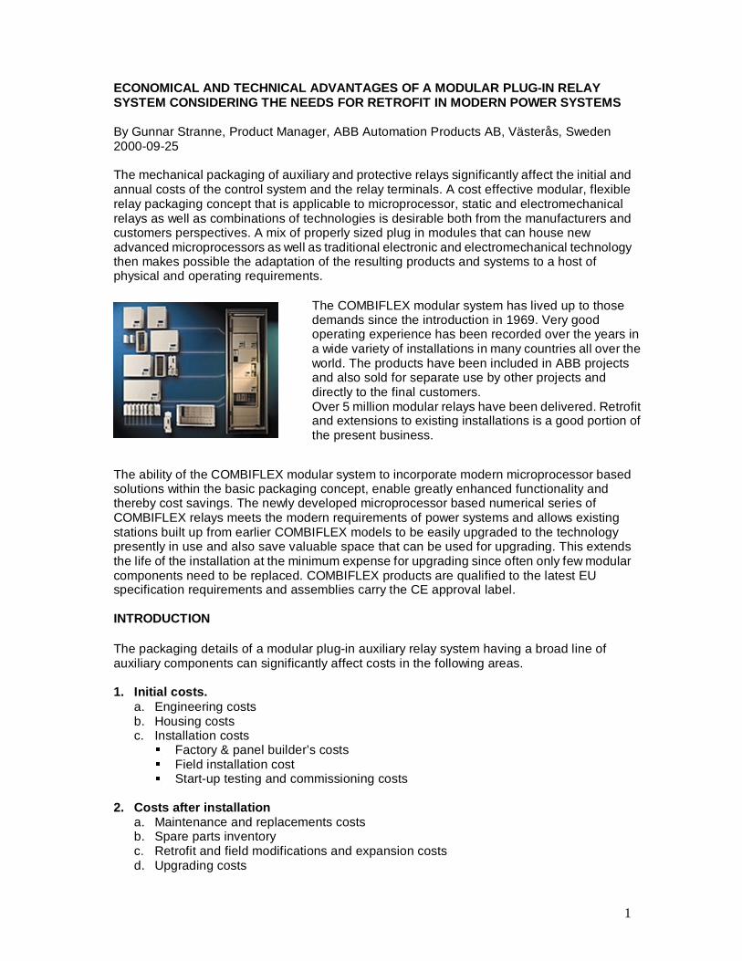
The COMBIFLEX modular system has lived up to those demands since the introduction in 1969. Very good operating experience has been recorded over the years in a wide variety of installations in many countries all over the world. The products have been included in ABB projects and also sold for separate use by other projects and directly to the final customers. Over 5 million modular relays have been delivered. Retrofit and extensions to existing installations is a good portion of the present business.
2
THE BASIC REQUIREMENTS 1. A Broad Product Line Transmission and generation and control terminals need to contain many relay functions. Some of these functions such as the primary protection measuring function in the past lend to the use of varying electronic relay designs and today the use of modern microprocessors. Other requirements such as electrical interfaces and needs for physical separation lends to the need for optical or electromechanical designs. The method of packaging of the various components must therefor be compatible with both microprocessor, static and electromechanical designs. Most relay terminals must interface with other control and alarm functions. The relay packaging should preferably provide many of these other functions and required features as ancillary modules are designed as integral parts of the system. In order to meet all the needs of a modern power system a broad product line is required. 2. Compactness The economy of standard designs of substations and auxiliary control panels requires that the assigned space for relaying be minimal, yet adequate for a variety of relay and control schemes. Similar needs exist in non-standard designs when relaying space must be allocated before the full relaying needs are identified. The relay packaging technique should provide for the needed compactness. 3. Flexibility Upgrading an existing relay terminal frequently poses the need to fit new relaying gear into a minimum space or space not originally planned for relaying use. The relay packaging should be flexible so as to provide a means to replace an existing relay package completely or in part with a space efficient design capable of handling the current and future relaying needs. 4. Rational Design To provide the desired flexibility, the functions within a given plug-in module should be at some rational minimum, but not so few as to result in excessive inter-module wiring. Considering the very wide range of functions needed for modern power system relay and control schemes, the packaging should physically consist of more than one module and one size. I.e. the building block system should be modularised with all sizes being compatible and capable of being intermixed (such as the 2 x 4’s and 2 x 6’s, etc., in the building construction business). The functionality should be designed in such a way that efficient construction and benefits from the volume of scale are derived from the resulting products needed to do the job. I.e. as many standardised modular functions as possible should be used. 5. Reliable Connections The number of screw terminals should be minimized since they are time-consuming to make especially in the field and are a potential hazard if not made correctly and tightened properly. This requirement is emphasized in a modular design with a large number of available interconnections. Also the personnel hazards should be minimized when working behind panels that may be wholly or partially energized. 6. High Quality and Workmanship The reliability of the products in the relay and control system to perform its intended function demands high quality of the workmanship and the internal design as well as the quality of packaging of the modules. Quality of material selection is also of importance to secure the best longevity of service.
3
7. Factory Assembly Factory labor costs are generally less than field labor costs. Thus the packaging should lend itself to sub-assembly of groups of modules as well as complete pre-assembly and wiring by the original ABB factory or other panel building shops or other OEM’s. 8. Local assembly Local assembly is desirable in many countries. Local assembly at various ABB Customer Centres and at independent OEM´s improve service and make sure wide spread competence is available closer to the customer location. This also improves the service degree. The possibility of providing local added value is also desirable. High volume low cost mass-produced modules can then combine with locally produced items and the necessary engineering meeting to meet the local customer requirements. Increased local assembly and value added is thereby encouraged by a modular building block concept. Local assembly and also production of COMBIFLEX is desirable. New IT tools disseminate information required for the proper engineering and to provide data for applications. Documents such as Buyers Guides, Users Guides and standard schematics that give the wiring information and technical application information can be downloaded via Internet. The big standard library available enables rational drafting and allow “cut and paste” engineering from a host of new ready-made engineering drawings available in commonly used CAD system formats. 9. User Assembly Many relay users are staffed and organized to build their own relay and control systems, especially those which require a one of a kind solution. The packaging system should be designed in such a way that no special skills are needed to assemble a system on site. 10. Test Features Another critical factor in upgrading an existing system installation, is the needed outage time for testing and verifying the installed equipment. The testing features provided in the relay package should permit safe testing even when other crews are still on the job site, thus minimizing the total installation time. 11. Maintenance The techniques required for trouble shooting and replacements of relays and other components should preferably be simplified as much as possible. Time required to remove a defective or outdated device and receive a modern replacement should be minimized. The modules should be sized so it is cost effective to replace a faulty module rather than repair and especially repair electronics in the field. The replaced component should preferably be analysed at the factory which gives the added advantage that any component or design failure can be evaluated by the factory designer. That provides valuable feedback to assure that each user gets the benefit of every user’s experience with the device and that the required improvements can be implemented in the products.
4
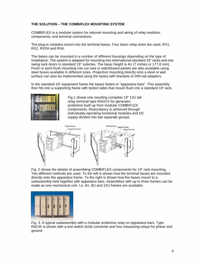
THE SOLUTION – THE COMBIFLEX MOUNTING SYSTEM COMBIFLEX is a modular system for rational mounting and wiring of relay modules, components, and terminal connections. The plug-in modules mount into the terminal bases. Four basic relay sizes are used, RX1, RX2, RX2H and RX4. The bases can be mounted in a number of different housings depending on the type of installation. The system is adapted for mounting into international standard 19” racks and into swing rack doors in standard 19” cubicles. The basic height is 4U (7 inches or 177,8 mm). Flush or semi-flush mounting into cut outs in switchboard panels are also available using steel boxes available in different sizes. Projection mounting directly onto a steel or wall surface can also be implemented using the bases with brackets or DIN-rail adapters. In the standard 19” equipment frame the bases fasten to ”apparatus bars”. This assembly then fits into a supporting frame with bolted sides that mount flush into a standard 19” rack.
Fig. 2 shows the details of assembling COMBIFLEX components for 19” rack mounting. Two different methods are used. To the left is shown how the terminal bases are mounted directly onto the apparatus frame. To the right is shown how the bases mount to a subassembly held together with apparatus bars. Assemblies with up to three frames can be made as one mechanical unit. I.e. 4U, 8U and 12U frames are available.
Fig. 3. A typical subassembly with a modular protective relay on apparatus bars. Type RACIK is shown with a test switch dc/dc converter and four measuring relays for phase and ground.
Fig.1 shows one resulting complete 19” 12U tall relay terminal type RAGCX for generator protection built up from modular COMBIFLEX components. Redundancy is achieved through individually operating functional modules and DC supply divided into two separate groups.
5
Plug-in modules
(92272)
Terminal bases
(94004)
Apparatus bars
(82532)
Relay assembly
(94832)
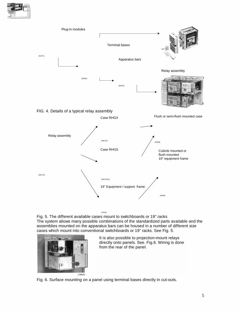
FIG. 4. Details of a typical relay assembly
Relay assembly
(900778)
Case RHGX
(940733)
Case RHGS
(SE970103)
19" Equipment / support frame
(75429)
Flush or semi-flush mounted case
(94909)
Cubicle mounted or flush-mounted19" equipment frame
(94909)
Fig. 5. The different available cases mount to switchboards or 19” racks The system allows many possible combinations of the standardized parts available and the assemblies mounted on the apparatus bars can be housed in a number of different size cases which mount into conventional switchboards or 19” racks. See Fig. 5.
Fig. 6. Surface mounting on a panel using terminal bases directly in cut-outs.
It is also possible to projection-mount relays directly onto panels. See. Fig.6. Wiring is done from the rear of the panel.
6
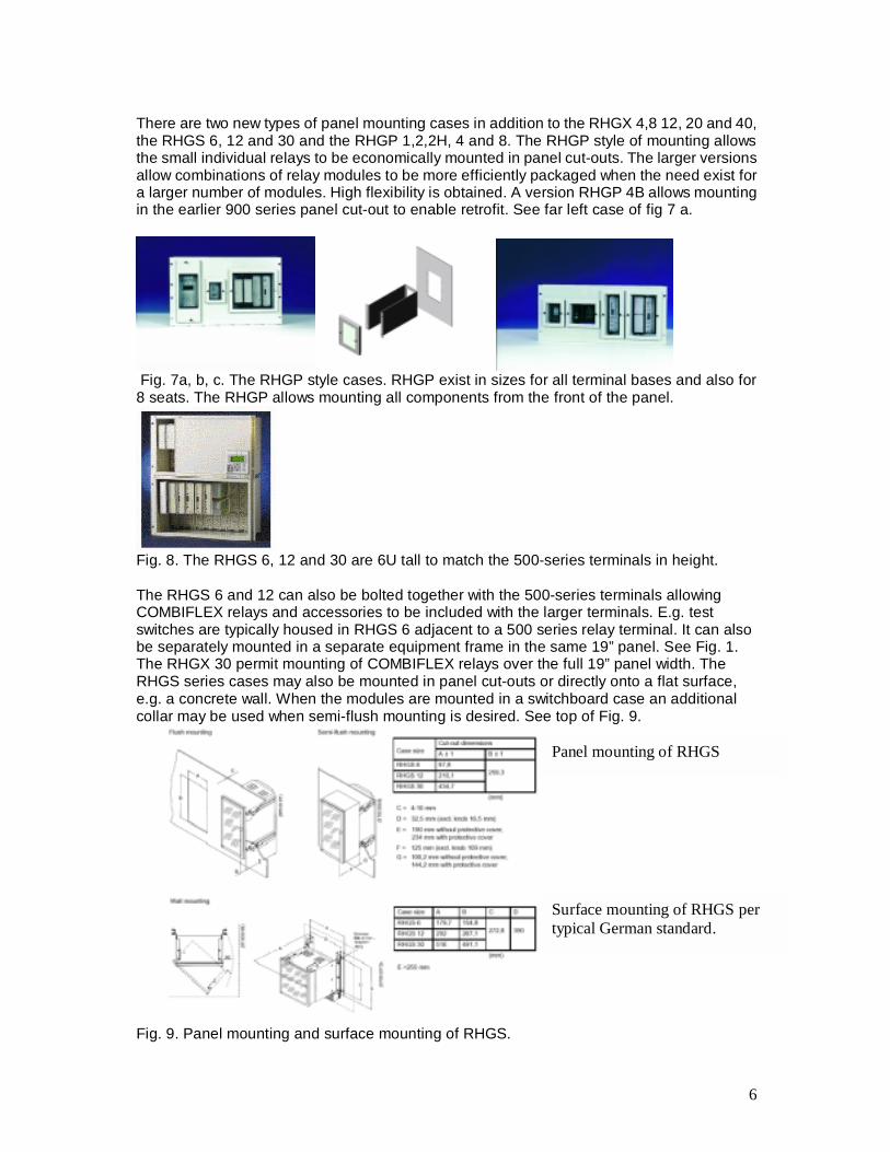
There are two new types of panel mounting cases in addition to the RHGX 4,8 12, 20 and 40, the RHGS 6, 12 and 30 and the RHGP 1,2,2H, 4 and 8. The RHGP style of mounting allows the small individual relays to be economically mounted in panel cut-outs. The larger versions allow combinations of relay modules to be more efficiently packaged when the need exist for a larger number of modules. High flexibility is obtained. A version RHGP 4B allows mounting in the earlier 900 series panel cut-out to enable retrofit. See far left case of fig 7 a.
Fig. 7a, b, c. The RHGP style cases. RHGP exist in sizes for all terminal bases and also for 8 seats. The RHGP allows mounting all components from the front of the panel.
Fig. 8. The RHGS 6, 12 and 30 are 6U tall to match the 500-series terminals in height. The RHGS 6 and 12 can also be bolted together with the 500-series terminals allowing COMBIFLEX relays and accessories to be included with the larger terminals. E.g. test switches are typically housed in RHGS 6 adjacent to a 500 series relay terminal. It can also be separately mounted in a separate equipment frame in the same 19” panel. See Fig. 1. The RHGX 30 permit mounting of COMBIFLEX relays over the full 19” panel width. The RHGS series cases may also be mounted in panel cut-outs or directly onto a flat surface, e.g. a concrete wall. When the modules are mounted in a switchboard case an additional collar may be used when semi-flush mounting is desired. See top of Fig. 9.
Fig. 9. Panel mounting and surface mounting of RHGS.
Surface mounting of RHGS per typical German standard.
Panel mounting of RHGS
7
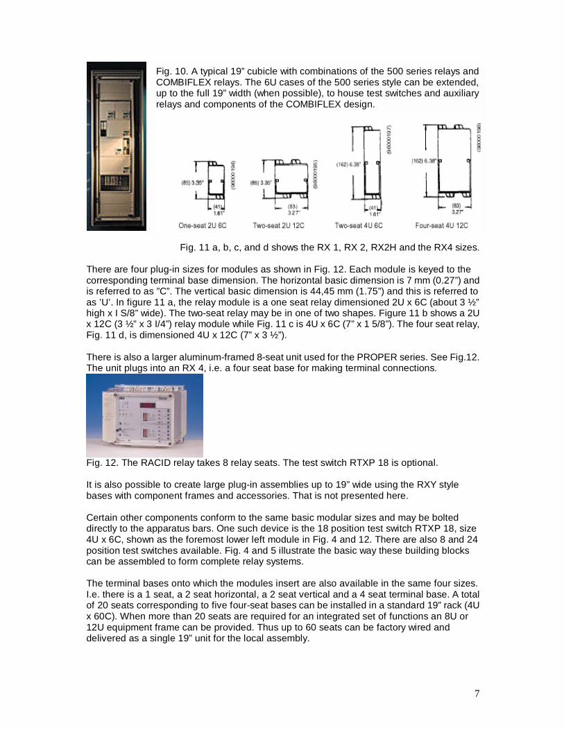
Fig. 11 a, b, c, and d shows the RX 1, RX 2, RX2H and the RX4 sizes. There are four plug-in sizes for modules as shown in Fig. 12. Each module is keyed to the corresponding terminal base dimension. The horizontal basic dimension is 7 mm (0.27”) and is referred to as ”C”. The vertical basic dimension is 44,45 mm (1.75”) and this is referred to as ’U’. In figure 11 a, the relay module is a one seat relay dimensioned 2U x 6C (about 3 ½” high x I S/8” wide). The two-seat relay may be in one of two shapes. Figure 11 b shows a 2U x 12C (3 ½” x 3 I/4”) relay module while Fig. 11 c is 4U x 6C (7” x 1 5/8”). The four seat relay, Fig. 11 d, is dimensioned 4U x 12C (7” x 3 ½”). There is also a larger aluminum-framed 8-seat unit used for the PROPER series. See Fig.12. The unit plugs into an RX 4, i.e. a four seat base for making terminal connections.
Fig. 12. The RACID relay takes 8 relay seats. The test switch RTXP 18 is optional. It is also possible to create large plug-in assemblies up to 19” wide using the RXY style bases with component frames and accessories. That is not presented here. Certain other components conform to the same basic modular sizes and may be bolted directly to the apparatus bars. One such device is the 18 position test switch RTXP 18, size 4U x 6C, shown as the foremost lower left module in Fig. 4 and 12. There are also 8 and 24 position test switches available. Fig. 4 and 5 illustrate the basic way these building blocks can be assembled to form complete relay systems. The terminal bases onto which the modules insert are also available in the same four sizes. I.e. there is a 1 seat, a 2 seat horizontal, a 2 seat vertical and a 4 seat terminal base. A total of 20 seats corresponding to five four-seat bases can be installed in a standard 19” rack (4U x 60C). When more than 20 seats are required for an integrated set of functions an 8U or 12U equipment frame can be provided. Thus up to 60 seats can be factory wired and delivered as a single 19” unit for the local assembly.
Fig. 10. A typical 19” cubicle with combinations of the 500 series relays and COMBIFLEX relays. The 6U cases of the 500 series style can be extended, up to the full 19” width (when possible), to house test switches and auxiliary relays and components of the COMBIFLEX design.
8
Bushing forexternal leads
16 terminalsTerminal base
With or withoutterminals
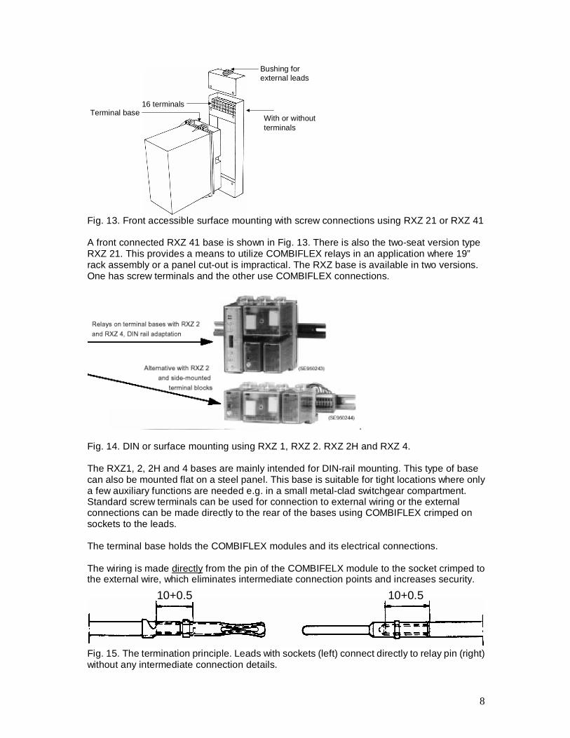
Fig. 13. Front accessible surface mounting with screw connections using RXZ 21 or RXZ 41 A front connected RXZ 41 base is shown in Fig. 13. There is also the two-seat version type RXZ 21. This provides a means to utilize COMBIFLEX relays in an application where 19” rack assembly or a panel cut-out is impractical. The RXZ base is available in two versions. One has screw terminals and the other use COMBIFLEX connections.
Fig. 14. DIN or surface mounting using RXZ 1, RXZ 2. RXZ 2H and RXZ 4. The RXZ1, 2, 2H and 4 bases are mainly intended for DIN-rail mounting. This type of base can also be mounted flat on a steel panel. This base is suitable for tight locations where only a few auxiliary functions are needed e.g. in a small metal-clad switchgear compartment. Standard screw terminals can be used for connection to external wiring or the external connections can be made directly to the rear of the bases using COMBIFLEX crimped on sockets to the leads. The terminal base holds the COMBIFLEX modules and its electrical connections. The wiring is made directly from the pin of the COMBIFELX module to the socket crimped to the external wire, which eliminates intermediate connection points and increases security.
10+0.5 10+0.5
Fig. 15. The termination principle. Leads with sockets (left) connect directly to relay pin (right) without any intermediate connection details.
9
ExtractorRTXD
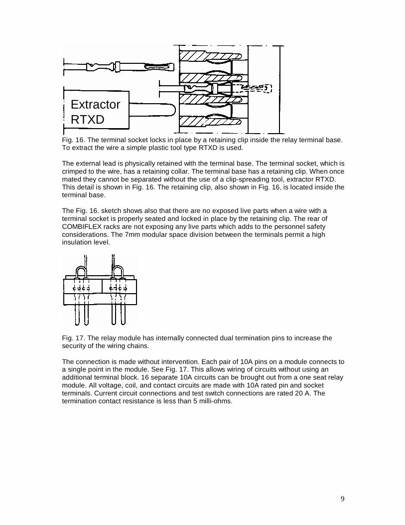
Fig. 16. The terminal socket locks in place by a retaining clip inside the relay terminal base. To extract the wire a simple plastic tool type RTXD is used. The external lead is physically retained with the terminal base. The terminal socket, which is crimped to the wire, has a retaining collar. The terminal base has a retaining clip. When once mated they cannot be separated without the use of a clip-spreading tool, extractor RTXD. This detail is shown in Fig. 16. The retaining clip, also shown in Fig. 16, is located inside the terminal base. The Fig. 16. sketch shows also that there are no exposed live parts when a wire with a terminal socket is properly seated and locked in place by the retaining clip. The rear of COMBIFLEX racks are not exposing any live parts which adds to the personnel safety considerations. The 7mm modular space division between the terminals permit a high insulation level.
Fig. 17. The relay module has internally connected dual termination pins to increase the security of the wiring chains. The connection is made without intervention. Each pair of 10A pins on a module connects to a single point in the module. See Fig. 17. This allows wiring of circuits without using an additional terminal block. 16 separate 10A circuits can be brought out from a one seat relay module. All voltage, coil, and contact circuits are made with 10A rated pin and socket terminals. Current circuit connections and test switch connections are rated 20 A. The termination contact resistance is less than 5 milli-ohms.
10
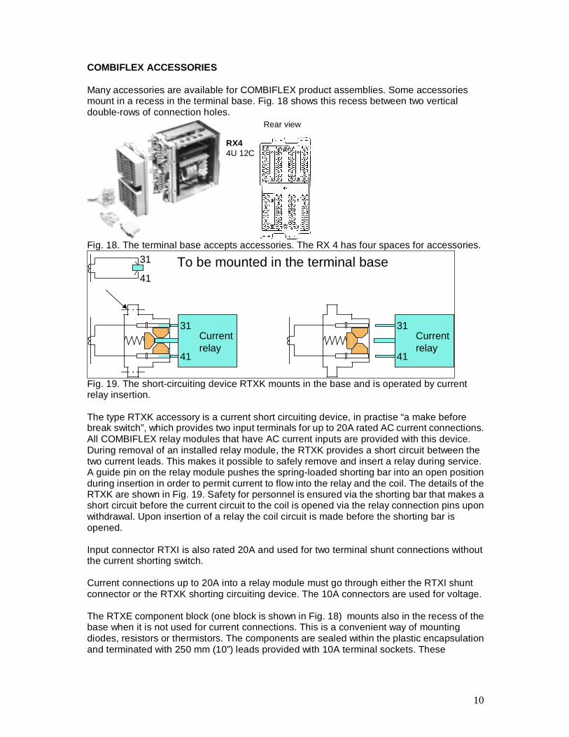
COMBIFLEX ACCESSORIES Many accessories are available for COMBIFLEX product assemblies. Some accessories mount in a recess in the terminal base. Fig. 18 shows this recess between two vertical double-rows of connection holes.
RX44U 12C
Rear view
Fig. 18. The terminal base accepts accessories. The RX 4 has four spaces for accessories.
Currentrelay
31
41
Currentrelay
31
41
31
41
To be mounted in the terminal base
Fig. 19. The short-circuiting device RTXK mounts in the base and is operated by current relay insertion. The type RTXK accessory is a current short circuiting device, in practise “a make before break switch”, which provides two input terminals for up to 20A rated AC current connections. All COMBIFLEX relay modules that have AC current inputs are provided with this device. During removal of an installed relay module, the RTXK provides a short circuit between the two current leads. This makes it possible to safely remove and insert a relay during service. A guide pin on the relay module pushes the spring-loaded shorting bar into an open position during insertion in order to permit current to flow into the relay and the coil. The details of the RTXK are shown in Fig. 19. Safety for personnel is ensured via the shorting bar that makes a short circuit before the current circuit to the coil is opened via the relay connection pins upon withdrawal. Upon insertion of a relay the coil circuit is made before the shorting bar is opened. Input connector RTXI is also rated 20A and used for two terminal shunt connections without the current shorting switch. Current connections up to 20A into a relay module must go through either the RTXI shunt connector or the RTXK shorting circuiting device. The 10A connectors are used for voltage. The RTXE component block (one block is shown in Fig. 18) mounts also in the recess of the base when it is not used for current connections. This is a convenient way of mounting diodes, resistors or thermistors. The components are sealed within the plastic encapsulation and terminated with 250 mm (10”) leads provided with 10A terminal sockets. These
11
accessory components are used for rectification, pickup and dropout delays, discharge resistors and voltage adaptations etc. A device called RTXV also mounts in the mentioned recess like RTXE. It is used to control that the level of the pick up voltage is above a safe value. This is used for auxiliary relays or optocoupled inputs that are not allowed to operate when the voltage is low or e.g. during transient voltage discharge due to DC battery ground faults or through installed capacitive surge-suppression devices. A variety of connectors are included in the COMBIFLEX system. The RTXG connector is used for rapid and simple connection and disconnection of leads and multi-core cables for example those between apparatus groups and individual cubicles. As a rule, the RTXG connector requires less space than the commonly used screw terminal blocks. The connector can be supplied as a single unit or assembled in blocks of two, four or six units. Packages of several RTXG bundled mechanically are used for quick connection of up to 48 double or 96 single 10A circuits simultaneously.
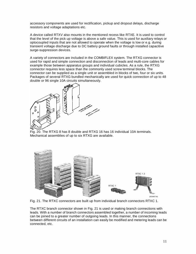
Fig. 20. The RTXG 8 has 8 double and RTXG 16 has 16 individual 10A terminals. Mechanical assemblies of up to six RTXG are available.
Fig. 21. The RTXC connectors are built up from individual branch connectors RTXC 1. The RTXC branch connector shown in Fig. 21 is used or making branch connections with leads. With a number of branch connectors assembled together, a number of incoming leads can be joined to a greater number of outgoing leads. In this manner, the connections between different circuits of an installation can easily be modified and metering leads can be connected, etc.
12
The branch connector has contact clips and silver-plated terminal pins built into a plastic holder. It is available with 10 A or 20 A terminals. The 10 A connector is beige and the 20 A connector is transparent. Up to four socket leads, for example one incoming and three outgoing, can be connected to the RTXC 1 branch connector. The RTXC component blocks are available in block of 20, 40, 60, 80 and 100. These blocks can be sized to fit almost any space. In approximately the same panel space occupied by the traditional 12 point screw down terminal block, the RTXG 100 provides 100 terminals with the following advantages.
1. Electrical isolation – Internal wiring is connected to one side of the block and all the field connections are made to the other side without any exposed electrical parts.
2. Rapid and reliable connection – This is accomplished by the quick socket
connection securely held in place by the retaining clip.
3. Space saving – About 8 times as many connections can be made in the space usually occupied by the typical screw terminal block.
4. Multiple connection – Any number of connections to a terminal can be
accommodated by jumping between individual RTXC connectors contained in a RTXC 100 connector block.
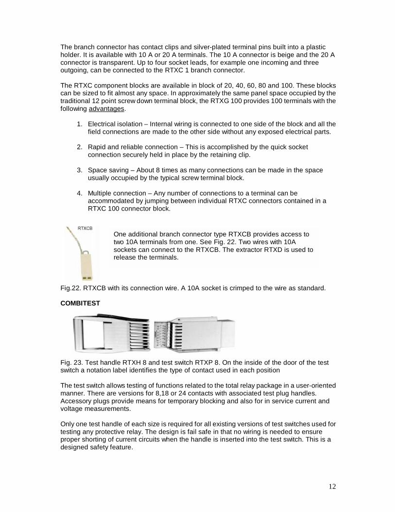
Fig.22. RTXCB with its connection wire. A 10A socket is crimped to the wire as standard. COMBITEST
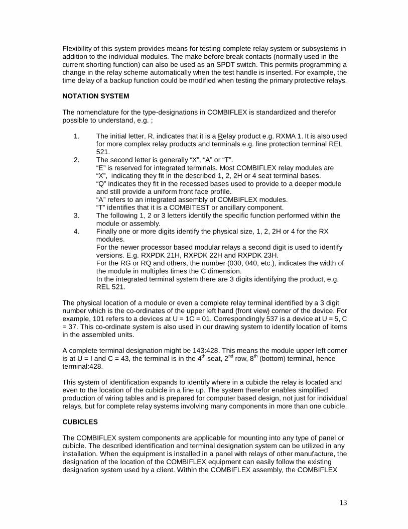
Fig. 23. Test handle RTXH 8 and test switch RTXP 8. On the inside of the door of the test switch a notation label identifies the type of contact used in each position The test switch allows testing of functions related to the total relay package in a user-oriented manner. There are versions for 8,18 or 24 contacts with associated test plug handles. Accessory plugs provide means for temporary blocking and also for in service current and voltage measurements. Only one test handle of each size is required for all existing versions of test switches used for testing any protective relay. The design is fail safe in that no wiring is needed to ensure proper shorting of current circuits when the handle is inserted into the test switch. This is a designed safety feature.
One additional branch connector type RTXCB provides access to two 10A terminals from one. See Fig. 22. Two wires with 10A sockets can connect to the RTXCB. The extractor RTXD is used to release the terminals.
13
Flexibility of this system provides means for testing complete relay system or subsystems in addition to the individual modules. The make before break contacts (normally used in the current shorting function) can also be used as an SPDT switch. This permits programming a change in the relay scheme automatically when the test handle is inserted. For example, the time delay of a backup function could be modified when testing the primary protective relays. NOTATION SYSTEM The nomenclature for the type-designations in COMBIFLEX is standardized and therefor possible to understand, e.g. ;
1. The initial letter, R, indicates that it is a Relay product e.g. RXMA 1. It is also used for more complex relay products and terminals e.g. line protection terminal REL 521.
2. The second letter is generally “X”, “A” or “T”. “E” is reserved for integrated terminals. Most COMBIFLEX relay modules are “X”, indicating they fit in the described 1, 2, 2H or 4 seat terminal bases. “Q” indicates they fit in the recessed bases used to provide to a deeper module and still provide a uniform front face profile. “A” refers to an integrated assembly of COMBIFLEX modules. “T” identifies that it is a COMBITEST or ancillary component.
3. The following 1, 2 or 3 letters identify the specific function performed within the module or assembly.
4. Finally one or more digits identify the physical size, 1, 2, 2H or 4 for the RX modules. For the newer processor based modular relays a second digit is used to identify versions. E.g. RXPDK 21H, RXPDK 22H and RXPDK 23H. For the RG or RQ and others, the number (030, 040, etc.), indicates the width of the module in multiples times the C dimension. In the integrated terminal system there are 3 digits identifying the product, e.g. REL 521.
The physical location of a module or even a complete relay terminal identified by a 3 digit number which is the co-ordinates of the upper left hand (front view) corner of the device. For example, 101 refers to a devices at U = 1C = 01. Correspondingly 537 is a device at U = 5, C = 37. This co-ordinate system is also used in our drawing system to identify location of items in the assembled units. A complete terminal designation might be 143:428. This means the module upper left corner is at U = I and C = 43, the terminal is in the 4th seat, 2nd row, 8th (bottom) terminal, hence terminal:428. This system of identification expands to identify where in a cubicle the relay is located and even to the location of the cubicle in a line up. The system therefor enables simplified production of wiring tables and is prepared for computer based design, not just for individual relays, but for complete relay systems involving many components in more than one cubicle. CUBICLES The COMBIFLEX system components are applicable for mounting into any type of panel or cubicle. The described identification and terminal designation system can be utilized in any installation. When the equipment is installed in a panel with relays of other manufacture, the designation of the location of the COMBIFLEX equipment can easily follow the existing designation system used by a client. Within the COMBIFLEX assembly, the COMBIFLEX
14
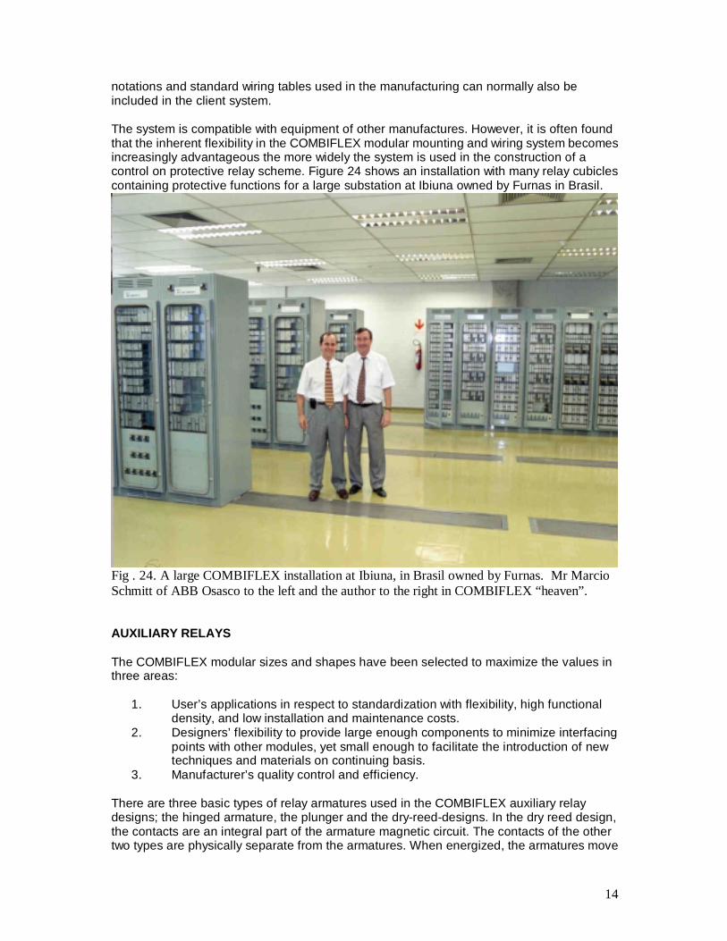
notations and standard wiring tables used in the manufacturing can normally also be included in the client system. The system is compatible with equipment of other manufactures. However, it is often found that the inherent flexibility in the COMBIFLEX modular mounting and wiring system becomes increasingly advantageous the more widely the system is used in the construction of a control on protective relay scheme. Figure 24 shows an installation with many relay cubicles containing protective functions for a large substation at Ibiuna owned by Furnas in Brasil.
Fig . 24. A large COMBIFLEX installation at Ibiuna, in Brasil owned by Furnas. Mr Marcio Schmitt of ABB Osasco to the left and the author to the right in COMBIFLEX “heaven”. AUXILIARY RELAYS The COMBIFLEX modular sizes and shapes have been selected to maximize the values in three areas:
1. User’s applications in respect to standardization with flexibility, high functional density, and low installation and maintenance costs.
2. Designers’ flexibility to provide large enough components to minimize interfacing points with other modules, yet small enough to facilitate the introduction of new techniques and materials on continuing basis.
3. Manufacturer’s quality control and efficiency. There are three basic types of relay armatures used in the COMBIFLEX auxiliary relay designs; the hinged armature, the plunger and the dry-reed-designs. In the dry reed design, the contacts are an integral part of the armature magnetic circuit. The contacts of the other two types are physically separate from the armatures. When energized, the armatures move
15
a small distance before mechanically engaging the moving contact assembly. With this physical separation, the armature and the moving contacts can each be designed for optimum performance. The result is low operating power, 1/3 to 7 watts for most standard types. 1 or 2 watts per seat is a typical value for signalling light to medium duty contact relays. RXMA 2 multiple contact relays with up to 15 sets of contacts consume only 2 watts as an example. There are four basic types of contacts: single, twin or bifurcated, bridge and dry-reed. The contact rating of relays is greatly influenced by relay contact bounce when making and breaking the circuit. Most of these COMBIFLEX relays have very little bounce, which minimize the contact arcing time. The making capacity is therefor 30A for 200ms or more. A new range of low cost auxiliary relays is now available for light to medium contact duty applications. The relays are designated RXMB1, RXMB2, RXMC1, RXMD1 and RXMD2. The light contact duty version is capable of tripping circuit breakers directly by allowing 30 A for 200 mS with L/R >= 10 mS to be passed. The interruption of the trip current is performed by the heavy duty auxiliary contact of the breaker. Normally the dual relay RXMB1 is used in signalling and auxiliary control circuits together with timers and measuring relays or other external equipment.
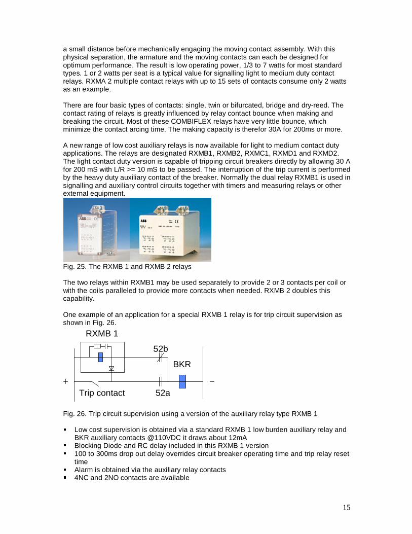
Fig. 25. The RXMB 1 and RXMB 2 relays The two relays within RXMB1 may be used separately to provide 2 or 3 contacts per coil or with the coils paralleled to provide more contacts when needed. RXMB 2 doubles this capability. One example of an application for a special RXMB 1 relay is for trip circuit supervision as shown in Fig. 26.
BKR
RXMB 1
52b
52aTrip contact
Fig. 26. Trip circuit supervision using a version of the auxiliary relay type RXMB 1 ��Low cost supervision is obtained via a standard RXMB 1 low burden auxiliary relay and
BKR auxiliary contacts @110VDC it draws about 12mA ��Blocking Diode and RC delay included in this RXMB 1 version ��100 to 300ms drop out delay overrides circuit breaker operating time and trip relay reset
time ��Alarm is obtained via the auxiliary relay contacts ��4NC and 2NO contacts are available
16
The RXMC1 is a fast acting dual auxiliary relay with medium duty contacts capable of interrupting more current than RXMB1. See table 1. The new RXMB 1, RXMB 2 and RXMC 1 relays are available with pin compatible configurations so earlier relay types e.g. RXMA 1, RXMA 2, RXMM 1 can be replaced in the field when needed. See BG for details and translation list from old catalog numbers to new. The RXMD1 is a bi-stable relay with light duty contacts. These relays provide possibilities of cost- and space-efficient assemblies of small control and auxiliary relay arrangements for a variety of installations. The quality of the low-cost product is ensured using the same protective relay standards as the other products in the COMBIFLEX range. RXMD2 is providing more contacts and can be used to replace RXMVB 2 pin-compatibly when lighter contacts are acceptable. The RXMD 1 and 2 require a slightly longer ON-OFF back to ON duty-cycle than RXMVB due to the internal capacitance. About 150ms is required for a new operation. The RXMD relays offer the very fast operating time of 5ms to change state ON-OFF or OFF-ON. The RXMT1 is a typical dry-reed relay module containing two independent relay elements each available with either a NO or NC contact and with an operating speed of 1 ms. This is mainly used when highest possible speed is required and the galvanic isolation offered by contacts.
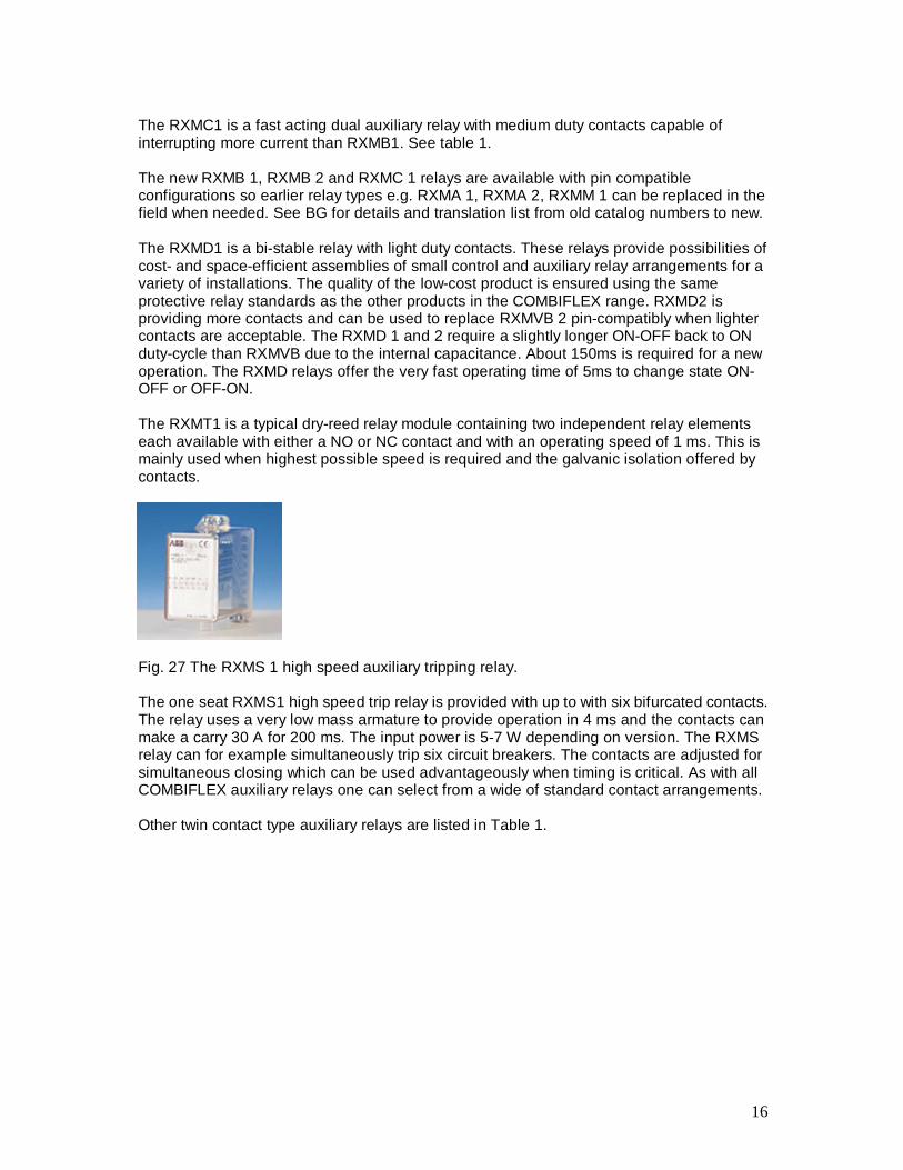
Fig. 27 The RXMS 1 high speed auxiliary tripping relay. The one seat RXMS1 high speed trip relay is provided with up to with six bifurcated contacts. The relay uses a very low mass armature to provide operation in 4 ms and the contacts can make a carry 30 A for 200 ms. The input power is 5-7 W depending on version. The RXMS relay can for example simultaneously trip six circuit breakers. The contacts are adjusted for simultaneous closing which can be used advantageously when timing is critical. As with all COMBIFLEX auxiliary relays one can select from a wide of standard contact arrangements. Other twin contact type auxiliary relays are listed in Table 1.
17
ABB Relays Auxiliary and Latching Relays Type of contact
Relay type Function Flags LED´s
Max no of contacts
Input Burden Operate time ms
Cont. A Break capacity A
Single RXMB1 RXMC1 RXMB2
Medium duty
2L 2x2 or 3
DC 2x1.1-1.8 W 5 or 8
5 0.3
RXMD1 RXMD2
Bi-stable 1L 3C+2 DC 0.1-0.7 W 5 5 0.2
RXMT1 Dual, Fast operation
- 2x1 DC 2x1.7 W 1 1 .0.8
Twin RXSF1 Dual target relay
2F 2x3 DC 2x1.6 W 40 5 .3
RXMA1 General purpose
- 7 ACDC
11 VA, 1.3 W 35 5 .3
RXMA2 General purpose
- 15 DC 3.8 W 55 5 .3
RXMS 1 High speed
- 6 DC 7 W 4 4 .25
Bridge RXME1 RXME18
General purpose
- 1
4 2
DC DC
2 W 30 6 2.5
RXMH2 Heavy duty
1 8 ACDC
9.5 VA 4 W
50 10 5
RXMVB2 RXMVB4
Latching/Lockout
1 -
8+2 14+2
ACDC
13 VA 2.5 W
20 10 3
Notes: 1. All twin and bridge relay contacts are capable of closing and carrying 30 A for 200 ms.
2. Faster operating times and time delayed operations available. Series resistor sizing for faster operation. See application data in BG.
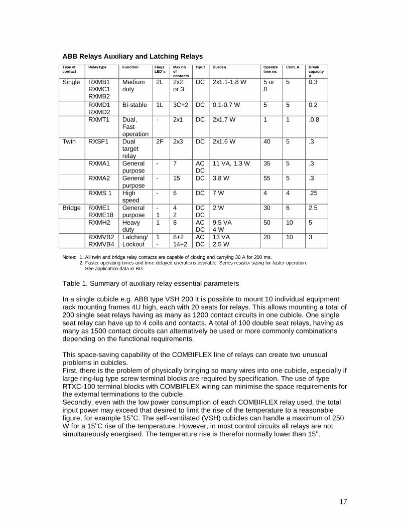
Table 1. Summary of auxiliary relay essential parameters In a single cubicle e.g. ABB type VSH 200 it is possible to mount 10 individual equipment rack mounting frames 4U high, each with 20 seats for relays. This allows mounting a total of 200 single seat relays having as many as 1200 contact circuits in one cubicle. One single seat relay can have up to 4 coils and contacts. A total of 100 double seat relays, having as many as 1500 contact circuits can alternatively be used or more commonly combinations depending on the functional requirements. This space-saving capability of the COMBIFLEX line of relays can create two unusual problems in cubicles. First, there is the problem of physically bringing so many wires into one cubicle, especially if large ring-lug type screw terminal blocks are required by specification. The use of type RTXC-100 terminal blocks with COMBIFLEX wiring can minimise the space requirements for the external terminations to the cubicle. Secondly, even with the low power consumption of each COMBIFLEX relay used, the total input power may exceed that desired to limit the rise of the temperature to a reasonable figure, for example 15oC. The self-ventilated (VSH) cubicles can handle a maximum of 250 W for a 15oC rise of the temperature. However, in most control circuits all relays are not simultaneously energised. The temperature rise is therefor normally lower than 15o.
18
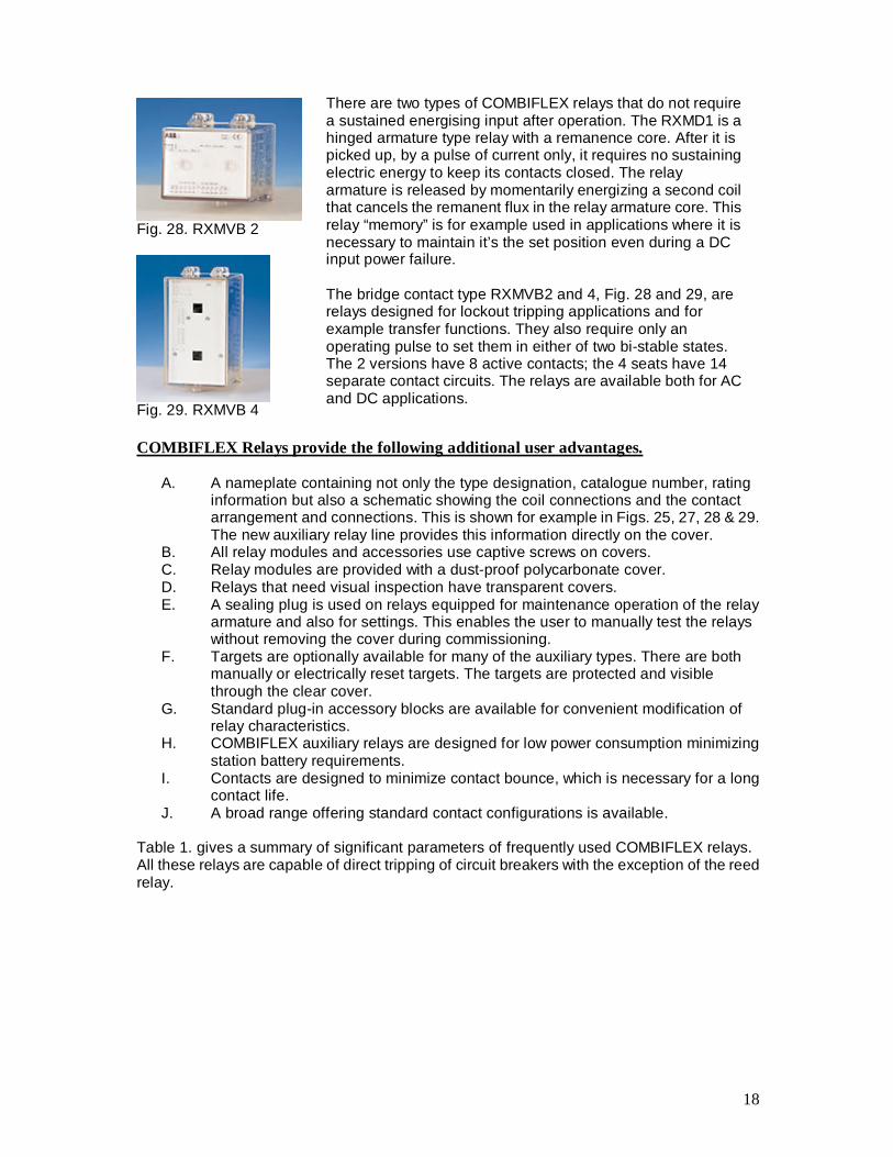
Fig. 28. RXMVB 2
Fig. 29. RXMVB 4 COMBIFLEX Relays provide the following additional user advantages.
A. A nameplate containing not only the type designation, catalogue number, rating information but also a schematic showing the coil connections and the contact arrangement and connections. This is shown for example in Figs. 25, 27, 28 & 29. The new auxiliary relay line provides this information directly on the cover.
B. All relay modules and accessories use captive screws on covers. C. Relay modules are provided with a dust-proof polycarbonate cover. D. Relays that need visual inspection have transparent covers. E. A sealing plug is used on relays equipped for maintenance operation of the relay
armature and also for settings. This enables the user to manually test the relays without removing the cover during commissioning.
F. Targets are optionally available for many of the auxiliary types. There are both manually or electrically reset targets. The targets are protected and visible through the clear cover.
G. Standard plug-in accessory blocks are available for convenient modification of relay characteristics.
H. COMBIFLEX auxiliary relays are designed for low power consumption minimizing station battery requirements.
I. Contacts are designed to minimize contact bounce, which is necessary for a long contact life.
J. A broad range offering standard contact configurations is available.
Table 1. gives a summary of significant parameters of frequently used COMBIFLEX relays. All these relays are capable of direct tripping of circuit breakers with the exception of the reed relay.
There are two types of COMBIFLEX relays that do not require a sustained energising input after operation. The RXMD1 is a hinged armature type relay with a remanence core. After it is picked up, by a pulse of current only, it requires no sustaining electric energy to keep its contacts closed. The relay armature is released by momentarily energizing a second coil that cancels the remanent flux in the relay armature core. This relay “memory” is for example used in applications where it is necessary to maintain it’s the set position even during a DC input power failure. The bridge contact type RXMVB2 and 4, Fig. 28 and 29, are relays designed for lockout tripping applications and for example transfer functions. They also require only an operating pulse to set them in either of two bi-stable states. The 2 versions have 8 active contacts; the 4 seats have 14 separate contact circuits. The relays are available both for AC and DC applications.
19
TIMING RELAYS The timing relays available in COMBIFLEX cover the setting range from 10 milliseconds to 99 hours (i.e. days). These relays use microprocessors or programmable custom integrated circuits. They provide built in pc-board mounted auxiliary output relays with contact. Very good accuracy is achieved and the new range replaces over 50 older timing relay models and versions with pin-compatible connection arrangements. This permits older installations to find new replacement relays for all timing purposes. Spares can be reduced to a few models covering the entire operating voltage range and timing of the earlier models.
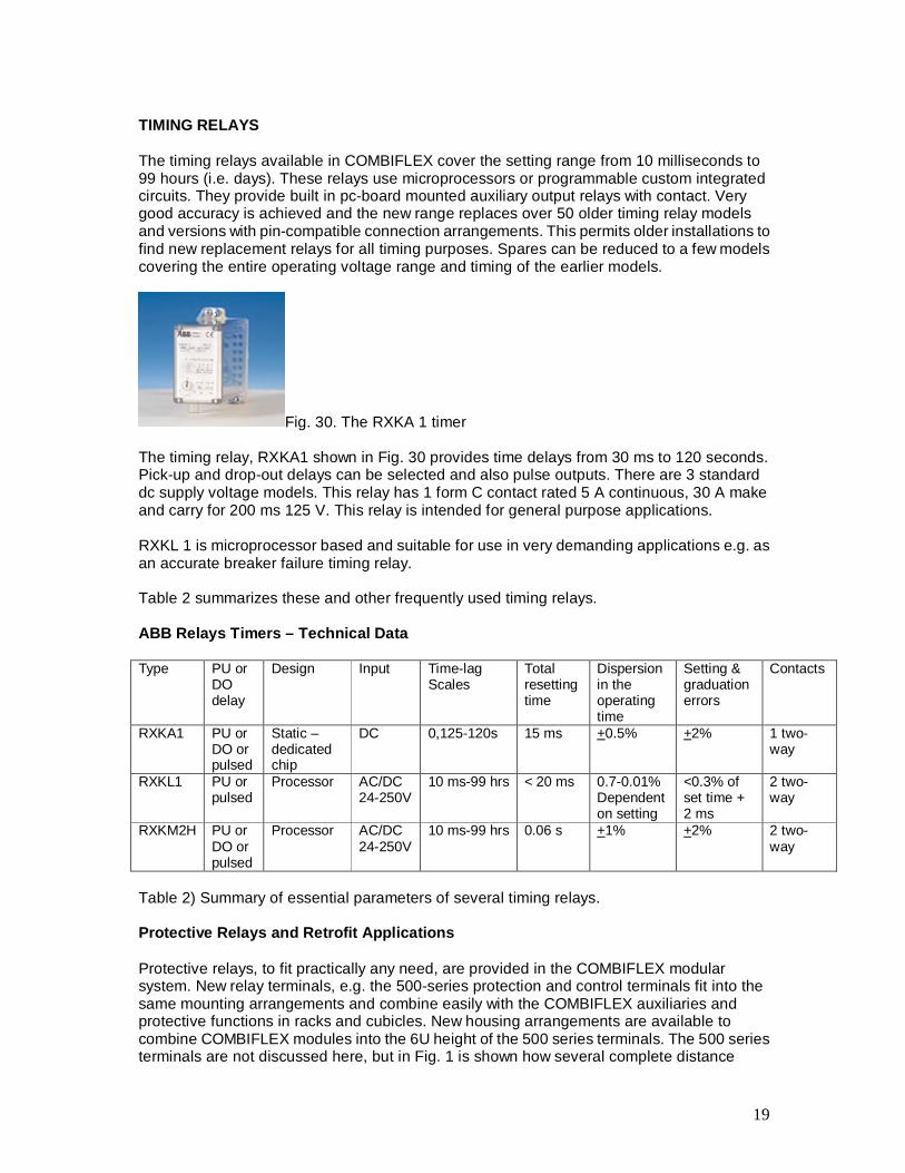
Fig. 30. The RXKA 1 timer The timing relay, RXKA1 shown in Fig. 30 provides time delays from 30 ms to 120 seconds. Pick-up and drop-out delays can be selected and also pulse outputs. There are 3 standard dc supply voltage models. This relay has 1 form C contact rated 5 A continuous, 30 A make and carry for 200 ms 125 V. This relay is intended for general purpose applications. RXKL 1 is microprocessor based and suitable for use in very demanding applications e.g. as an accurate breaker failure timing relay. Table 2 summarizes these and other frequently used timing relays. ABB Relays Timers – Technical Data Type PU or
DO delay
Design Input Time-lag Scales
Total resetting time
Dispersion in the operating time
Setting & graduation errors
Contacts
RXKA1 PU or DO or pulsed
Static –dedicated chip
DC 0,125-120s 15 ms +0.5% +2% 1 two-way
RXKL1 PU or pulsed
Processor AC/DC 24-250V
10 ms-99 hrs < 20 ms 0.7-0.01% Dependent on setting
<0.3% of set time + 2 ms
2 two-way
RXKM2H PU or DO or pulsed
Processor AC/DC 24-250V
10 ms-99 hrs 0.06 s +1% +2% 2 two-way
Table 2) Summary of essential parameters of several timing relays. Protective Relays and Retrofit Applications Protective relays, to fit practically any need, are provided in the COMBIFLEX modular system. New relay terminals, e.g. the 500-series protection and control terminals fit into the same mounting arrangements and combine easily with the COMBIFLEX auxiliaries and protective functions in racks and cubicles. New housing arrangements are available to combine COMBIFLEX modules into the 6U height of the 500 series terminals. The 500 series terminals are not discussed here, but in Fig. 1 is shown how several complete distance
20
relays now can be housed in one cubicle. It is expected that sizes continue to shrink as available components do that at the same time the capability increases. The COMBIFLEX modular building block system is used to provide complete Protection Schemes. One shown example is a Generator Protection scheme using the RAGCX relay. RAGCX combines available standard modular components to make a specially tailored generator protection scheme. Previously this would have occupied a whole 19” rack using the earlier design principles and relays. With the introduction of the new compact measuring modules, having higher functionality than before, the earlier more space consuming individual protection assemblies are practically speaking shrunk into individual plug-in units.
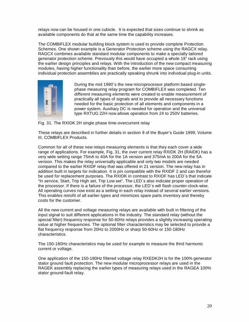
Fig. 31. The RXIDK 2H single phase time-overcurrent relay These relays are described in further details in section 9 of the Buyer’s Guide 1999, Volume III, COMBIFLEX Products. Common for all of these new relays measuring elements is that they each cover a wide range of applications. For example, Fig. 31, the over current relay RXIDK 2H (RAIDK) has a very wide setting range 75mA to 40A for the 1A version and 375mA to 200A for the 5A version. This makes the relay universally applicable and only two models are needed compared to the earlier RXIDF relay that was offered in 21 version. The new relay has in addition built in targets for indication. It is pin compatible with the RXIDF 2 and can therefor be used for replacement purposes. The RXIDK in contrast to RXIDF has LED´s that indicate “In service, Start, Trip High set, Trip Low set”. The LED´s also indicate proper operation of the processor. If there is a failure of the processor, the LED´s will flash counter-clock-wise. All operating curves now exist as a setting in each relay instead of several earlier versions. This enables retrofit of all earlier types and minimizes spare parts inventory and thereby costs for the customer. All the new current and voltage measuring relays are available with built in filtering of the input signal to suit different applications in the industry. The standard relay (without the special filter) frequency response for 50-60Hz relays provides a slightly increasing operating value at higher frequencies. The optional filter characteristics may be selected to provide a flat frequency response from 20Hz to 2000Hz or sharp 50-60Hz or 150-180Hz characteristics. The 150-180Hz characteristics may be used for example to measure the third harmonic current or voltage. One application of the 150-180Hz filtered voltage relay RXEDK2H is for the 100% generator stator ground fault protection. The new modular microprocessor relays are used in the RAGEK assembly replacing the earlier types of measuring relays used in the RAGEA 100% stator ground-fault relay.
During the mid 1990´s the new microprocessor platform based single-phase measuring relay program for COMBIFLEX was completed. Ten different measuring elements were created to enable measurement of practically all types of signals and to provide all necessary functions needed for the basic protection of all elements and components in a power system. Auxiliary DC is needed for operation and the universal type RXTUG 22H now allows operation from 24 to 250V batteries.
21
The new single-phase based measuring microprocessor relays in the star 2H series and their replaced earlier relay types are found in the Table 2. ; Relay type Function and earlier relay replacement possibilities RXIDK 2H RXIDF 2H replacement. Also RXIDE 4 can be functionally replaced RXIDG21 H/RAIDG Replacing RXIDG2H special logarithmic characteristic Time-Over-
Current relay for selective sensitive ground fault relaying. RXVK2H/RAVK Replaces RXVE thermal over-current protection. RXEDK 2H/RAEDK New two-stage selectable over or under voltage relay with inverse
of fixed time delay, replacing or offering an alternative to many earlier products. RXEL, RXEF, RXEG etc
RXFK 2H/RAFK New two-stage frequency relay module replaces single stage RXFE 4 and provides an alternate dF/dt function to the second stage in addition. The assemblies are suitable for many different applications such as load shedding. 10mHz or 25mHz setting resolution is available.
RXLK 2H/RALK New V/Hz relay for over excitation protection of transformers and generators. Replaces RATUB and provides new inverse functions suitable for different protected objects.
RXPDK 2H/RAPDK* Three versions of directional overcurrent and ground relays replacing RXPE/RXIDF combinations and RXPF 4, RAEPA etc.
RXISK 2H/RAISK Voltage restraint overcurrent relay. Replaces combinations of overcurrent and undervoltage relays e.g. RXIDF 2H or RXIDK 2H with RXIG 2 or RXEDK 2H.
RXZK 2H/RAZK* New multi-purpose single zone and dual zone and out of step impedance relays. These relays may substitute RXZF 2 and RXZK 4 and assemblies, e.g. acc to RF640021 E
RXPPK 2H/RAPPK Reverse power relays replacing RXPE 40 etc * In order to improve the operation of directional overcurrent and impedance relays for close in faults when the polarizing voltage disappears a controlled voltage memory function is provided for the RXPDK 21H and the RXZK 21H and RXZK22H. Table 2. New star 2H series relays. Three-phase multifunction protective relays During the late 1990´s the COMBIFLEX developments have been focused on multi-phase relays and also new mounting arrangements and production improvements. The following multi-phase relays have been introduced in order to enable more efficient packaging and substitution of some earlier relay types where component supplies are dwindling and production difficulties exist. RXEDA 1 three-phase overvoltage relay with definite time delay setting. The relay does not require a separate auxiliary DC battery voltage supply for operation and can therefor replace earlier electromechanical relays such as single phase or three-phase assemblies of the RXEC 1 and RXED 1 and also the RXEL 2. The relay is suitable for AC and DC operation. RXEDA 1 can also be used as an undervoltage relay but then a separate timer is needed when time-delayed function is required. E.g. the RXKL 1 or RXKA 1 can be used.
22
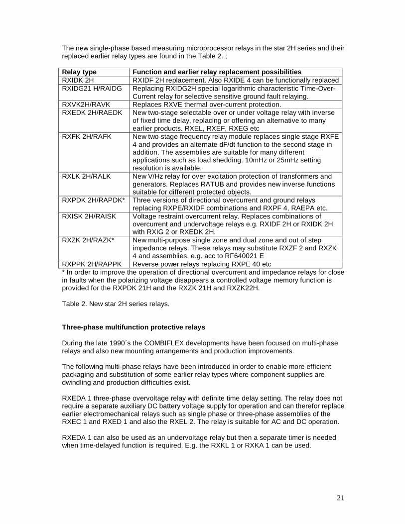
The star one platform allows functions to be programmed into a very small amount of space. The RXETB 1 is a three-phase fuse failure relay replacing the earlier RXETA 1 type that contained a mercury wetted contact not permissible to be used for environmental reasons.
RXHL 401 three-phase and ground overcurrent relay replacing the RXIDE 43 and RXIDK 4 and some versions of RACID, RACIC RXHL 411 three-phase and ground overcurrent multifunction relay. This relay offers a replacement for the three-phase and ground overcurrent RACIB, RACIC and three-phase thermal overload relay RXVE 43 and the RXIDK 4 and some versions of the RAICA breaker failure relay. In addition the reclosing relay function of RACIB is optional. The wide setting range offered for phase overcurrent and separately set for groundfaults makes its possible to adapt to most system applications including high voltage. Versions allow different rating of the ground current input transformer to enable applications for all types of system grounding methods, i.e. solid, medium and high impedance, resistor or reactor grounded systems. The breaker failure function is complete with separately settable current detector levels for phase and ground. The settings are permitted to be below rated current as initiation of the BFR function only takes place after a trip command has been given. This provides good sensitivity. The relay can therefor be used as a free-standing BFR. The three-phase thermal overcurrent function is based on a true thermal replica model that is set in the relay. The current settings are separatee from the three levels of time-overcurrent functions. All the IEC standard curves NI, VI, EI are available as well as the RI (ASEA-curve) and the Long time inverse curve. The logarithmic RXIDG curve is also available as a setting for the ground element. This curve is mainly used in the 400kV systems in Scandinavia. There are two opto-coupled inputs and five programmable output relays that can be tied to any of the relay functions. One output can be used for the processor internal supervision and the processor watch-dog. DC supply is taken from a standard RXTUG 22H, suitable for all battery voltages from 24V to 250V. RXHL 421 Same as RXHL 411 but two-phase overcurrent and a directional ground relay function for high impoedance grounded systems. Can replace e.g. RACIB and combinations of discrete relays e.g. RXIDE 43 with RXPE 4.
Fig. 32. RXETB 1 is a three-phase fuse failure relay based on the same platform as the three-phase voltage relay type RXEDA 1. A very small amount of space is required and no auxiliary DC is needed.
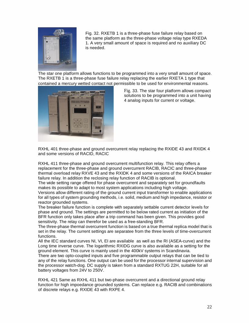
Fig. 33. The star four platform allows compact solutions to be programmed into a unit having 4 analog inputs for current or voltage.
23
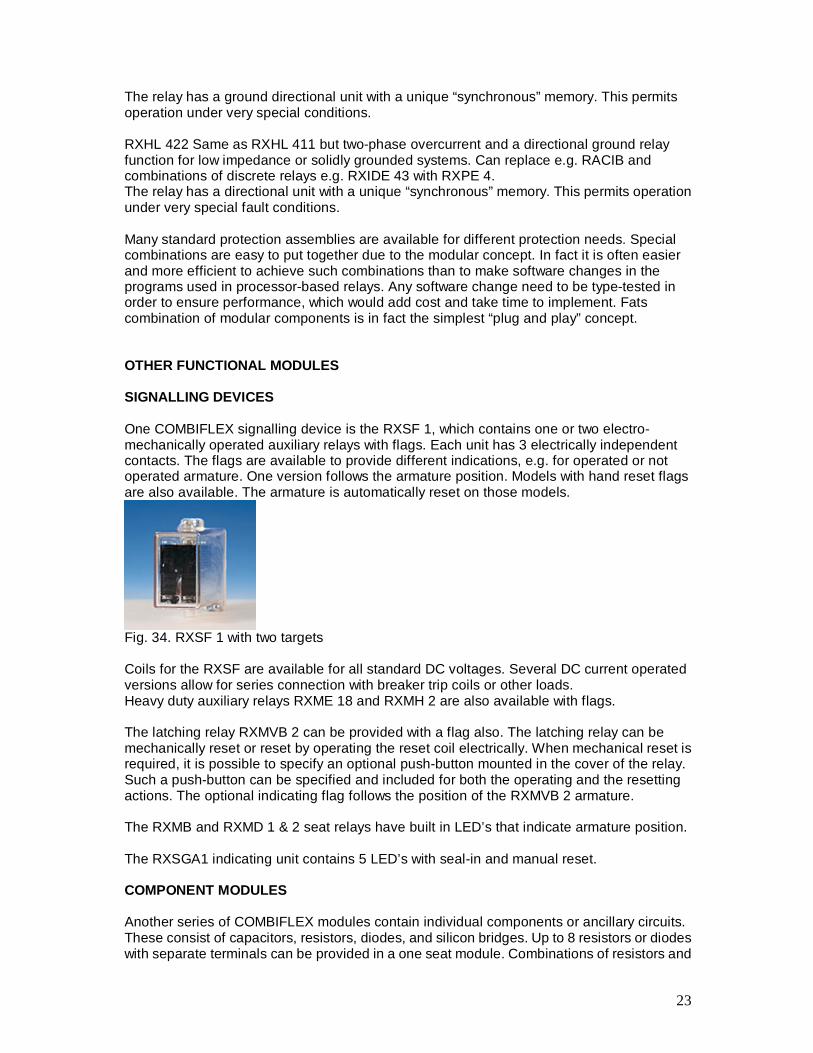
The relay has a ground directional unit with a unique “synchronous” memory. This permits operation under very special conditions. RXHL 422 Same as RXHL 411 but two-phase overcurrent and a directional ground relay function for low impedance or solidly grounded systems. Can replace e.g. RACIB and combinations of discrete relays e.g. RXIDE 43 with RXPE 4. The relay has a directional unit with a unique “synchronous” memory. This permits operation under very special fault conditions. Many standard protection assemblies are available for different protection needs. Special combinations are easy to put together due to the modular concept. In fact it is often easier and more efficient to achieve such combinations than to make software changes in the programs used in processor-based relays. Any software change need to be type-tested in order to ensure performance, which would add cost and take time to implement. Fats combination of modular components is in fact the simplest “plug and play” concept. OTHER FUNCTIONAL MODULES SIGNALLING DEVICES One COMBIFLEX signalling device is the RXSF 1, which contains one or two electro-mechanically operated auxiliary relays with flags. Each unit has 3 electrically independent contacts. The flags are available to provide different indications, e.g. for operated or not operated armature. One version follows the armature position. Models with hand reset flags are also available. The armature is automatically reset on those models.
Fig. 34. RXSF 1 with two targets Coils for the RXSF are available for all standard DC voltages. Several DC current operated versions allow for series connection with breaker trip coils or other loads. Heavy duty auxiliary relays RXME 18 and RXMH 2 are also available with flags. The latching relay RXMVB 2 can be provided with a flag also. The latching relay can be mechanically reset or reset by operating the reset coil electrically. When mechanical reset is required, it is possible to specify an optional push-button mounted in the cover of the relay. Such a push-button can be specified and included for both the operating and the resetting actions. The optional indicating flag follows the position of the RXMVB 2 armature. The RXMB and RXMD 1 & 2 seat relays have built in LED’s that indicate armature position. The RXSGA1 indicating unit contains 5 LED’s with seal-in and manual reset. COMPONENT MODULES Another series of COMBIFLEX modules contain individual components or ancillary circuits. These consist of capacitors, resistors, diodes, and silicon bridges. Up to 8 resistors or diodes with separate terminals can be provided in a one seat module. Combinations of resistors and
24
capacitors are also available. One such unit is the RXTCB 1 impulse storing device. This may be used to catch very short pulses and permit operation of auxiliary relays. For example a high speed RXMS 1 relay used with the impulse storing device can operate and seal-in from a pulse as short as ½ ms. The contacts of the relay close in the normal operating time 3-4ms of the RXMS 1 relay. This method is used in the RADSS high speed bus differential relay. CONTROL PACKAGES This article shows that the COMBIFLEX system includes a complete line of functional modules. These are assembled into a system to meet substantially all needs of a user. The packages can be factory designed and assembled or they can be made up by the user. In addition to the basic relays described these packages can include other specified components. ECONOMIC ADVANTAGES The economics of standard designs are well recognized. Utility standards are frequently limited to a required non-modular moulded case auxiliary relay and timer design. Very often those relays are specified to have screw terminals. The required space is often large due to the specified need for ring lug terminals. With the modular COMBIFLEX design, up to 80 relay functions or 150 contact outputs can be provided in a 4U standard 19” equipment frame. This compact and modular design impacts favourably on the total cost. The lack of any foreseeable obsolescence will reduce future costs when system requirements change and revisions in the COMBIFLEX system are needed. Especially as new models are introduced with increased functionality and further reduced space requirements, this will provide very good overall economy. COMBIFLEX scores favourably in installed component labor cost. Rack mounted devices are easier and less costly to mount as compared to mounting individual moulded case or industrial grade equivalents. Rack mounting does not require the expensive and time consuming process of punching individual cut-outs in steel panels and the broad line of COMBIFLEX components to select from greatly the need for mounting individual devices. Physical mounting effort has been conservatively estimated at about 25% of the other methods. COMBIFLEX wiring costs is estimated at about 20% of the traditional screw connections. The inherent and costly problems of intermittent connections and the exposed electrical hot points representing physical and potential hazards to personnel are eliminated by the safety features of the locked COMBIFLEX pin and socket connection. COMBIFLEX is faster, easier and less costly to modify or expand. Steel-panel changes are not normally required and the associated drafting, engineering, steel and labor costs are therefore greatly reduced. The modular plug-in design of relays, other component devices and all the connections provides additional cost savings in field labor. Where time is of the essence it is not necessary to wait for the relays to start the panel assembly. Relay bases, which are available from stock, can be mounted and wired in parallel with the relay production at the factory or at the local assembly location. This will enable utilities, switchboard assemblers, and the factory to schedule there more efficiently and not be handicapped by the frequent problem of component device shortages. Short factory delivery times typically 4 weeks of high volume standard components also aid in this matter.
25
COMBIFLEX also offers a flexible and convenient shelf storing feature. Spare or future relays can be mounted and stored in either unfilled or spare rack mounted equipment frames. The relays and bases can be utilized for future expansion or replacement purposes. COMBIFLEX offers a broad product line of auxiliary relays to select from with a large variety of contact arrangements. Special functions can be accomplished with fewer relays having more available contacts and optional features. The COMBIFLEX system is not limited to mounting just electromechanical relays but can accommodate a wide variety of electrical apparatus including timing relays, signalling and target relays, current, voltage, power and impedance relays, and other protective relays, and functional packages. Another cost savings are evident in the low continuous power consumption and station battery requirements as compared to other traditional designs. Special custom solutions can be economically created by the user without requiring any special programming or design skills. The quality embodied in the concept and the design combined with well conceived manufacturing procedures ensures significantly reduced time and expense to locate and clear problems when using the modular COMBIFLEX approach. The basic mechanical dimensions of the COMBIFLEX system have now been used about 30 years and evolved from the former “RR” plug-in system introduced over 50 years ago. Continuous vitalization is an ongoing process to maintain the product line at a competitive level. The Relays of the RR design are still in service at many locations, giving an indication of the quality and workmanship that goes into our products. Even its fixed case – mounted predecessors e.g. the type RI relays are still “going strong” despite use since the 1920´s at many locations world-wide. We do have its modern replacements available! COMBIFLEX relays are in service world-wide with extensive installation in the tropics and desert areas, as well as northern latitude of U.S. and Europe. The system meets ANSI and IEC standards. Seismic vibration testing according to ANSI standard C37.98 have been performed and the evaluated fragility levels for COMBIFLEX relays and components are available upon request. Many of the relays have been tested and approved for nuclear applications in the US as well as in Sweden and other countries. Modern relays have a designed life-expectancy of about 25 years. Many of the earliest installations of COMBIFLEX relays and components are therefor due to be replaced within the foreseeable future. It is the intention of ABB to enable ease of replacement with the presently available modern and coming new models of the COMBIFLEX design. CONCLUSION With the continuing introduction of modern technology into the COMBIFLEX system the COMBIFLEX mounting system is expected to have a continuing future in the field of protection and control in the OEM market as well as for the power system customers that build their own relay and control panels. Retrofit of existing installations will become important as the deregulation process continues to put increased pressure on profitability. Cost efficiency is emphasized in the new product developments and refinements of existing products. A complete single phase measuring protective relay series exist to enable the needs of maintaining existing COMBIFLEX installations in service many more years to come. Multi-phase multi-function devices have been introduced to fit the latest customer specification requirements and to allow even more compact and space saving installations.