Embed Size (px)
Citation preview

Medium Voltage Products
Technical guideActive Users in accordance with Standard CEI 0-16

2

3
Table of contents
4 The environmental and socio-economical advantages of renewable energy sources
5 1. Active Users in accordance with Standard CEI 0-16
8 2. Operating conditions of the production plant
13 3. The ABB solutions

4
The environmental and socio-economical advantages of renewable energy sources
The renewable energy sources have acquired a key role in the future of energy policies. Many governments have decided to develop an aggressive long-term action aimed at an increasing importance of “clean energy”, with the aim of ensuring alternative energy sources and a decentred production as against traditional sources based on the exploitation of fossil fuels.
The latest international agreements with great economic and political impact include the famous “Climate-energy Package 20-20-20”. This agreement, made within the European Council in December 2008, envisages a 20% cut in the emission of “greenhouse” gases, a 20% increase in energy efficiency, and a 20% increase in the share of renewable energy sources by the year 2020.
The ultimate aim is to increasingly generate more energy by means of systems capable of limiting atmospheric pollution and gas emissions which cause the greenhouse effect, identified as the factors mainly responsible for the global warming of the planet.
Bibliography
The contents of this guide have been prepared in accordance with the texts of the following publications:• CEI 0-16 Ed. II, July 2008: Reference technical rules for the
connection of active and passive Users to the HV and MV networks of electricity distribution Companies
• CEI 82-25 Ed. II, December 2008: Guide to the design and installation of photovoltaic generation systems connected to Medium and Low Voltage electrical networks.
• CEI 0-16 V2, April 2009, Interpretation Sheet F1: Reference technical rules for the connection of active
and passive Users to HV and MV networks of electricity distribution Companies.

5
1. Active Users in accordance with Standard CEI 0-16
Renewable energy sources are forms of energy generated by sources which, by their intrinsic nature, generate or “do not run out” within human lifetimes, and their use does not affect the natural resources for future generations.
According to Italian reference standards, renewable sources include:« ...the sun, wind, water sources, geothermal sources, seas, wave motion and the transformation of plant products and organic and inorganic wastes into electricity…»
(CEI 0-16, 2008-07, paragraph 4)According to the connection technical rules, the distribution network Users are differentiated into:• Active users: installations which contain any kind of
machinery (rotary or static) which converts all forms of useful energy into electrical energy in alternate current envisaged for operating in parallel (also transient) with the grid belong to this category of Users.
• Passive users: this category contains all installations that do not fall within the previous definition.

6
D M U
Wh
Pmax
varh
SL SL SC
31
2C
1.1. Connection diagram between substations and active User installation
(CEI 0-16, 2008-07, paragraph 8.2)Starting with the MV cable downline of the delivery point, the Figure given shows the diagram of the user installation for the connection. With reference to the above-mentioned Figure, the substation is the station constructed for connecting the User installation. In case of active Users, if the measurement
devices are to be provided by the User (feeder points), these must be located immediately downline of the main device, in such a position as to be protected (against the fault currents coming from the network) from the general device.
Connection cable (Provided by User)
Feeder application
Feeder application
Legend:
D = delivery station M = measurement roomU = User roomSL = line compartmentSC = delivery compartmentC = delivery point 1 = measurement unit2 = User’s general device3 = compartment present/to be provided for incoming-outgoing connection
Fig. 1 Connection diagram between substation and active User installation (source: CEI 0-16, 2008-07, paragraph 8.2)
1. Active Users in accordance with Standard CEI 0-16
7
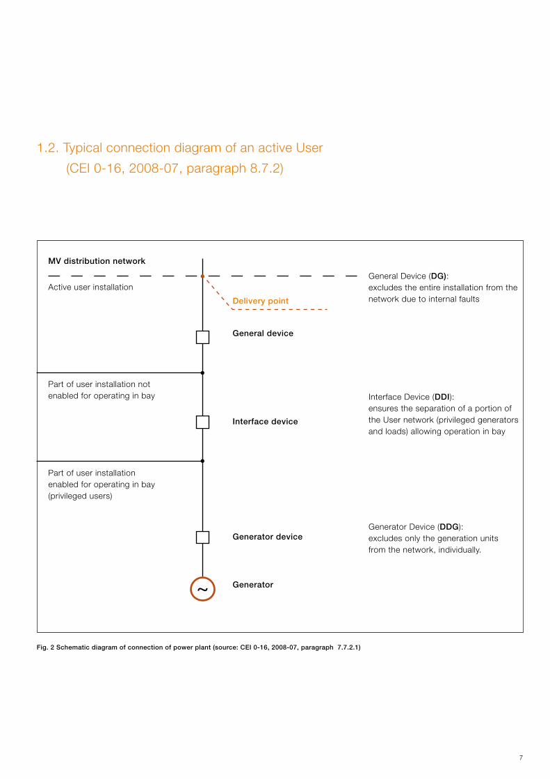
1.2. Typical connection diagram of an active User
(CEI 0-16, 2008-07, paragraph 8.7.2)
Fig. 2 Schematic diagram of connection of power plant (source: CEI 0-16, 2008-07, paragraph 7.7.2.1)
MV distribution network
General Device (DG):excludes the entire installation from the network due to internal faults
Active user installation
General device
Interface Device (DDI): ensures the separation of a portion of the User network (privileged generators and loads) allowing operation in bay
Generator Device (DDG): excludes only the generation units from the network, individually.
Part of user installation not enabled for operating in bay
Part of user installation enabled for operating in bay (privileged users)
Interface device
Delivery point
Generator device
Generator

8
(CEI 0-16, 2008-07, paragraph 8.7.3) The operation of a production plant in parallel with the distribution network must respect the following conditions: • must not cause disturbances to the service on the
distribution network;• must stop immediately and automatically in the absence of
power supply or if the mains voltage and frequency values are not within the values specified by the Distributor;
• the parallel device of the production plant must not allow the parallel with the network in case of power failure or voltage and frequency values outside the values specified by the Distributor.
To ensure the separation of the production plant from the distribution network in case of power failure an Interface Device (DDI) must be installed.The Interface Protection System (SPI), by acting on the DDI, separates the production plant from the distributor network, thereby preventing:• the User from supplying the network in case of power failure
in the mains:• the User from continuing to power the fault in case of a fault
on the MV line to which the active User is connected;• the generator from being out-of-phase with the network
in case of automatic or manual re-closure of the circuit-breakers of the distribution network.
2. Operating conditions of the production plant
2.1. Devices providedOn production plants, apart from the General Device (DG), active Users must be provided with the following devices to guarantee the parallel with the network::(CEI 0-16, 2008-07, paragraph 8.7.4)– interface device (DDI), capable of ensuring the separation of
a portion of the User installation (generators and privileged loads) allow their isolated operation, as well as working of the installation in parallel with the grid;
– generator device (DDG) capable of excluding only the generation units individually from the network.
The general, interface and generator devices must be located in the User installation.It must be possible for an operator to carry out the opening command of the afore-mentioned devices manually as well as automatically by the User protections.The User is in charge of operating the devices.
2.1.1. General Device (DG)
The general device (DG) is defined by the CEI 0-16 as follows:(CEI 0-16, 2008-07, paragraph 3.13)Operation and disconnecting equipment the opening of which (controlled by the General Protection System) ensures the separation of the entire User installation from the network.
The DG consists of a general disconnector immediately downline of the delivery point and a main circuit-breaker provided immediately downline of the disconnect switch or a withdrawable circuit-breaker capable of excluding the connection of the user installation from the network system.
The General device must provide for the following protections:• overload I>, 51;• polyphase short-circuit (delayed), I >>, 51;• polyphase short-circuit (instantaneous), I >>, 50;• single-phase earth fault Io> (51N);• single-phase double earth fault Io>>, 50N;• earth fault directional for compensated neutral 67NC or
isolated neutral 67NI.

9
The ABB protection relays suitable for such application and conforming to standard CEI 0-16 are:
1. REF 601 if the earth fault directional protection for compensated neutral (67NC) and isolated neutral (67NI) is not necessary. It may be omitted when the contribution of the single-phase earth fault capacitive current does not exceed 80% of the regulation current defined by the Distributor for the 51N protection.
2. REF542plus if the directional protection against earth faults is also required for compensated neutral (67NI) or isolated neutral (67NC).

10
2.1.2. Interface Device (DDI)
The interface device (DDI) is defined by the CEI 0-16 as follows:(CEI 0-16, 2008-07, paragraph 3.11)One (or more) operating apparatus the opening of which (controlled by a special protection system) ensures the separation of the production plant from the network, allowing the production plant to operate in bay on privileged loads.(CEI 0-16, 2008-07, paragraph 8.7.4.1)The DDI can be installed on the MV as well as LV side. If installed on the MV side, it must consist of:• a withdrawable three-pole switch with opening release in
case of power failureor
a three-pole switch with opening release in case of power • failure and two disconnect switches installed one upline and the other downline of the circuit-breaker.
For installations with a number of generators, as a rule, there must be a single interface device (in MV or LV) and such as to simultaneously exclude all the generators.
Greater details are given in the F1 interpretation sheet of the CEI 0-16 V2 Edition 2009-04, which defines that, if the DDI is installed on the MV side, it may consist of:• a three-pole switch with opening release in case of power
failure and a disconnectors installed one upline or downline of the circuit-breaker.
The presence of two disconnectors (one upline and the other downline of the DDI) must be considered by the User depending on the safety requirements in the maintenance phase.
For plant installation reasons, a number of interface protections can be installed, one for each generator; in this case, to avoid degrading the reliability of the system, the activation command of each protection must act on all the DDIs present in the installation. This will allow disconnection of all the generators of the network if there is a fault due to just one SPI (Interface Protection System).2.1.2.1. Protections associated with the DDI
The function of the interface protection is to isolate the part of the active user’s system, including the generator, in case of:– external faults in the User network;– opening of the primary substation (CP) switch at the top of
the line.
(CEI 0-16, 2008-07, paragraph 8.7.5.1)The Interface Protection System (SPI) associated with the DDI includes frequency, voltage and, possibly, homopolar voltage relays.The following protections must be provided:1. maximum voltage (without intentional delay), 59.S1, 59.S2;2. minimum voltage (typical delay: 300ms), 27.S1, 27.S2;3. maximum frequency (without intentional delay), 81 > S1, 81
> S2;4. minimum frequency (without intentional delay), 81 < S1,
81< S2;5. maximum homopolar voltage Vo on MV side (delayed),
59Vo;6. protection against power failure (to be defined in agree-
ment between the Distributor and the User according to the features of the distribution network).
Thresholds S1 are those which are normally active. Thresholds S2 are activated/deactivated by means of a dedicated external command, this command must be able to simultaneously activate/deactivate threshold S1.The ABB protection relay suitable for such application and conforming to standard CEI 0-16 is the REF542plus.
2. Operating conditions of the production plant

11
If the Interface Device (DDI) coincides with the General Device (DG) it is possible to have the protection of the above-mentioned devices by means of a single relay. With this solution, it is possible to combine the General Protection System (SPG) and the Interface System (SPI) in a single appliance. ABB proposes the REF542plus protection relay.
The homopolar maximum voltage protection (59Vo) is only envisaged if the installation is capable of supporting the mains voltage, by means of voltage generators, with total powers ≥ 400 kVA.In case of a photovoltaic system, even with powers ≥ 400kVA, where the inverters have the function of current generators the homopolar maximum voltage protection (59Vo) is not necessary.
2.1.2.2. Back-up for DDI opening failure
(CEI 0-16, 2008-07, paragraph 8.7.5.2)For the operating safety of the network, in cases where production is by means of generators capable of supporting the mains voltage (synchronous generators, self-energized asynchronous, inverters functioning as voltage generators), for powers greater than 400 kVA a back-up must be provided for the interface device opening failure.The support consists in restoring the activation command, given by the interface protection, to another interruption device. It consists of a circuit which acts, as the case may be, on the general device and on the generator device, with a ≤ 1 s delay. The timer is activated by the interface protection activation circuit.
In case of photovoltaic systems, even with installations having powers ≥ 400 kVA, there is no need to provide back-up for a DDI opening failure.
2.1.3. Generator Device (DDG):
The generator device (DDG) is defined by the CEI 0-16 as follows:(CEI 0-16, 2008-07, paragraph 3.10)Operating equipment the opening of which (controlled by a protection system provided for the purpose) determines the separation of the generation unit.Like the DDI, the DDG can be installed on the MV as well as the LV side.
(CEI 0-16, 2008-07, paragraph 8.7.4.2)for MV generation units, the DDG device may consist of:– a withdrawable three-pole circuit-breaker with opening
release, or;– a three-pole switch with opening release and a disconnector
installed on the side of the circuit-breaker network.For LV generation units, the DDG device may consist of an automatic circuit-breaker.
The DDG can carry out the functions of the DDI, if it has the necessary features. Two circuit-breakers in series with one another or a circuit-breaker and a contactor must always be present between the generation and the distribution network.
2.2. Parallel control device(CEI 0-16, 2008-07, paragraph 8.7.5.6)At least one of the devices, DG, DDI and DDG must be equipped with a control device of the circuit-breaker which checks the conditions for the parallel immediately upline and downline of the operating device.If one of the said devices (DG, DDI, DDG) is not equipped with a parallel control, it must be provided with an automation mechanism which prevents closure if power is present immediately downline.
The parallel control device is normally outside the above-mentioned protections, this is why ABB switchgears are equipped with a pair of terminals in series at the DG, DDI and DDG closure release. The enable signal from the device which handles synchronism of the generator with the network or power failure downline will be sent to these signals.

12

13
3. The ABB solutions
3.1. Lay-out of installation type if the DI coincides with the DDG in MV 143.1.1. ABB solution 1a for substations - DI coinciding with DG in MV 15 3.1.2. ABB solution 1b for substations - DI coinciding with DG in MV and panel for dedicated UTIF measurements 16 3.1.3. ABB solution 1c for substations - DI coinciding with DG in MV without panel for UTIF measurements and with the use of phase toroidal CT 183.1.4. ABB solution 2 simplified for substations - DI coinciding with DG in MV 20
3.2. Lay-out of installation type if the DI is different from DG in MV 223.2.1. ABB solution 3a for substations - DI different from DG in MV 23 3.2.2. ABB solution 3b for substations with dedicated UTIF measurement panel and use of voltage and current sensors for PG - DI different from DG in MV 24
3.3. Lay-out of installation type if the DI is different from DDG in LV 263.3.1. ABB solution 4a - DI different from DDG in LV UTIF energy
measurement in MV 273.3.2. ABB solution 4b – DI different from DDG in LV with UTIF energy measurement in MV and phase toroidal CT 28
3.4. Lay-outs – type of substation for generation bay power supply 29

14
I>
Io>
67N
PG
PI
Vo>
V>V<
f>f<
DG + DI
3. The ABB solutions
3.1. Lay-out of installation type if the DI coincides with the DG in MV
Delivery pointSubstation
User system
Distribution network
Distributor
Measurement of incoming energy to network
MV loads
LV loads
MV/LV transformers
D gen
DI opening failure back-up

15
TV f/f
TAo
DI + DG
REF542 plus
TA
TV f/t
500
1950
500 750 500 375/500 375/500
UTIF
UTIF
3.1.1. ABB solution 1a for substations - DI coinciding with DG in MV
A P2 P1F R P3 P3 connector
2 A fuses

16
TV f/f
TAo
DI + DG
REF542 plus
TA
TV f/t
TV f/tUTIF
TAUTIF
500
1950
500 750 375/500 375/500500 500
3. The ABB solutions
3.1.2. ABB solution 1b for substations - DI coinciding with DG in MV and panel for dedicated UTIF measurement
A P2 P1F R Rac P3 P3 connector
2 Afuses

17
Primary 1st Secondary2nd Secondary (for 1a solution)
No. 3 CT 300/1-5
I> (51)I>> (51) I>>> (50)Io>> (50N)
UTIFmeasurements
Primary Secondary
No. 1 CThomopolar
40/1 67N
Primary 1st Secondary2nd Secondary (for 1a solution)
Notes
No. 3 VT phase/earth
depends on operating voltage
59VoUTIFmeasurements
1st secondary connected in open delta
Primary Secondary
No. 2 VT phase/phase
depends on operating voltage
V< (27.S1, 27.S2), V> (59.S1, 59.S2), f<, f> (81.S1, 81.S2)
ABB solution 1a or 1b switchboard composition
- A: unit with earthing switch (alternatively Rac with mobile earthing);- P2: unit with switch-disconnector and fuses;- P1F: unit with circuit-breaker;- R: riser unit;- P3 incoming/outgoing line unit with switch-disconnector (alternatively P1F unit), for powering generator bay.- In case of a single generator, it is possible to replace the P3 incoming/outgoing units with a P2 unit for the power supply and
protection of MV/LV transformers;- In case of privileged loads power supply insert a P2 unit between the R riser unit and the P3 incoming/outgoing units for the
power supply and protection of MV/LV transformers.
Type of relay Relay function Protections Notes
REF542plusConsists of:- No. 2 I/O boards- No. 8 inputs for homopolar CT/VT/CT
PG + PI
I> (51), I>> (51), I>>> (50) Overload and short-circuit
Io>> (50N) Double single-phase earth fault
67N* Directional against earth fault, compensated/isolated neutral
V< (27.S1, 27.S2) V> (59.S1, 59.S2) Minimum and maximum voltage
f< (81.S1, 81.S2), f> (81.S1, 81.S2) Minimum and maximum frequency
59Vo** Maximum homopolar voltage
* 67N depends on the value of the single-phase earth fault capacitive current and therefore on the length of the installation (see paragraph 2.1.1 General Device DG)
** 59Vo not necessary in case of photovoltaic system

18
A P2 P1F
TV f/f
TAo
DI + DG
REF542 plus
TA TV f/t
500
1950
500 750
3. The ABB solutions
3.1.3. ABB solution 1c for substations - DI coinciding with DG in MV without panel for UTIF measurements and with the use of phase toroidal CT
2 Afuses
MV/LVTrafo
Generator
19
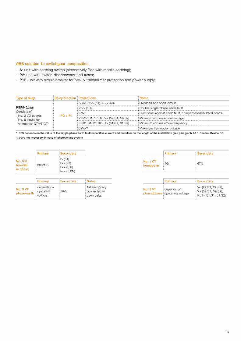
ABB solution 1c switchgear composition
- A: unit with earthing switch (alternatively Rac with mobile earthing);- P2: unit with switch-disconnector and fuses;- P1F: unit with circuit-breaker for MV/LV transformer protection and power supply.
Primary Secondary
No. 3 CT toroidal in phase
300/1-5
I> (51)I>> (51) I>>> (50)Io>> (50N)
Primary Secondary
No. 1 CT homopolar
40/1 67N
Primary Secondary Notes
No. 3 VT phase/earth
depends on operating voltage
59Vo 1st secondary connected in open delta
Primary Secondary
No. 2 VT phase/phase
depends on operating voltage
V< (27.S1, 27.S2), V> (59.S1, 59.S2), f<, f> (81.S1, 81.S2)
Type of relay Relay function Protections Notes
REF542plusConsists of:- No. 2 I/O boards- No. 8 inputs for homopolar CT/VT/CT
PG + PI
I> (51), I>> (51), I>>> (50) Overload and short-circuit
Io>> (50N) Double single-phase earth fault
67N* Directional against earth fault, compensated/isolated neutral
V< (27.S1, 27.S2) V> (59.S1, 59.S2) Minimum and maximum voltage
f< (81.S1, 81.S2), f> (81.S1, 81.S2) Minimum and maximum frequency
59Vo** Maximum homopolar voltage
* 67N depends on the value of the single-phase earth fault capacitive current and therefore on the length of the installation (see paragraph 2.1.1 General Device DG)
** 59Vo not necessary in case of photovoltaic system

20
TV f/f
TAo
DI + DG
REF542 plus
TA
500
1950
500 750 500 375/500 375/500
3. The ABB solutions
3.1.4. ABB solution 2 simplified for substations - DI coinciding with DG in MV
In the following conditions:- 67N not necessary- 59Vo not necessary (case
of photovoltaic system)- UTIF measurements not
required in substation
A P2 P1F R P3 P3 connector
2 Afuses

21
ABB solution 2 switchgear composition
- A: unit with earthing switch (alternatively Rac with mobile earthing);- P2: unit with switch-disconnector and fuses;- P1F: unit with circuit-breaker;- R: riser unit;- P3 incoming/outgoing line unit with switch-disconnector (alternatively P1F unit), for powering generator bay.- In case of a single generator, it is possible to replace the P3 incoming/outgoing units with a P2 unit for the power supply and
protection of MV/LV transformers;- In case of privileged loads power supply insert a P2 unit between the R riser unit and the P3 incoming/outgoing units for the
power supply and protection of MV/LV transformers.
Type of relay Relay function Protections Notee
REF542plusconsisting of:- no. 2 I/O boards- No. 8 inputs for homopolar CT/VT/CT
PG + PI
I> (51), I>> (51), I>>> (50) Overload and short-circuit
Io>> (50N) Double single-phase earth fault
V< (27.S1, 27.S2) V> (59.S1, 59.S2) Minimum and maximum voltage
f< (81.S1, 81.S2), f> (81.S1, 81.S2) Minimum and maximum frequency
Primary Secondary
No. 3 CT 300/1-5
I> (51)I>> (51) I>>> (50)Io>> (50N)
Primary Secondary
No. 1 CT homopolar
40/1 67N
Primary Secondary
No. 2 VT phase/phase
depends on operating voltage
V< (27.S1, 27.S2), V> (59.S1, 59.S2), f<, f> (81.S1, 81.S2)

22
DG
I>
Io>
67N
PG
Vo>
V>V<
f>f<
PI
DIMT
3. The ABB solutions
3.2. Diagram of installation type if the DI is different from DG in MV
Delivery pointSubstation
User system
Distribution network
Distributor
Measurement of incoming energy to network
Non-privileged MV loads
LV loads
MV/LV transformers
D gen
Privileged MV loads
DI opening failure back-up

23
TV f/f
TAo
DG
REF542 plus
UTIF
TV f/t
DI
500
1950
375/500375/500375750 750500
TA
3.2.1. ABB solution 3a for substations - DI different from DG in MV
A P1F Rac P1F R P3 P3 cable output connector
REF542plusor non-ABB relay

24
TV f/f
TAo
DG
REF542 plus
DI
TV f/tUTIF
TAUTIF
500
19
50
375/500375/500375750 750500 500
3. The ABB solutions
3.2.2. ABB solution 3b for substations with dedicated UTIF measurement panel and use of voltage and current sensors for PG - DI different from DG in MV
A P1F Rac Rac P1F R P3 P3 cable feeder connector
REF542plusor non-ABB relay
combisensor

25
ABB solution 3a or 3b switchboard composition
- A: unit with earthing switch (alternatively Rac with mobile earthing);- P1F: unit with circuit-breaker;- Rac: riser unit;- P3 incoming/outgoing line unit with switch-disconnector (alternatively P1F unit), for powering generator bay.- In case of a single generator, it is possible to replace the P3 incoming/outgoing units with a P2 unit for the power supply and
protection of MV/LV transformers;- In case of privileged loads power supply insert a P2 unit between the R riser unit and the P3 incoming/outgoing units for the
power supply and protection of MV/LV transformers.- In case of non-privileged loads insert a P2 unit between the R/Rac riser unit and the P1F unit for the power supply and
protection of MV/LV transformers.
Type of relay Relay function Protections Notes
REF542plus PG
I> (51), I>> (51), I>>> (50) Overload and short-circuit
Io>> (50N) Double single-phase earth fault
67N* Directional against earth fault, compensated/isolated neutral
REF542plusornot-ABB type
PI
V< (27.S1, 27.S2) V> (59.S1, 59.S2) Minimum and maximum voltage
f< (81.S1, 81.S2), f> (81.S1, 81.S2) Minimum and maximum frequency
59Vo** Maximum homopolar voltage
* 67N depends on the value of the single-phase earth fault capacitive current and therefore on the length of the installation (see paragraph 2.1.1 General Device DG)If the 67N protection is not necessary, the REF 601 relay can be used as the DG.
** 59Vo not necessary in case of photovoltaic system
Primary Secondary
No. 1 CT homopolar
40/1 67N
Primary Secondary
No. 2 VT phase/phase
dipends on operating voltage
V< (27.S1, 27.S2), V> (59.S1, 59.S2), f<, f> (81.S1, 81.S2)
Possibility of using a single REF542plus relay for PI+PG if the DI and DG are situated on the switchgear, for solution 3a only.
Primary Secondary
No. 3 CT 300/1-5
I> (51)I>> (51) I>>> (50)Io>> (50N)
Primary 1st Secondary2nd Secondary(for 3a solution)
Notes
No. 3 VT phase/earth
dipends on operating voltage
59Vo UTIF measurements
1st secondary connected in open delta

26
DG
I>
Io>
67N
PG
Vo>
V>V<
f>f<
PI
DIBT
3. The ABB solutions
3.3. Diagram of installation type if the DI is different from DDG in LV
Delivery pointSubstation
User system
Distribution network
Distributor
Measurement of incoming energy to network
MV loads
Privileged LV loads
MV/LV transformers
D gen
Non-privileged LV loads
DI opening failure back-up
27
TV f/t
TA
P1A Rac Rac P3 P3
TAo
DG
REF542 plus
TV UTIF
TA UTIF
1950
375/500375/500750 500 500
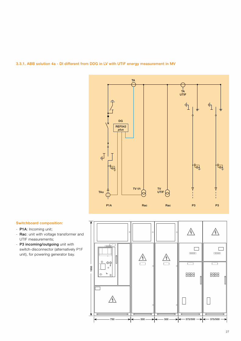
3.3.1. ABB solution 4a - DI different from DDG in LV with UTIF energy measurement in MV
Switchboard composition:
- P1A: Incoming unit;- Rac: unit with voltage transformer and
UTIF measurements;- P3 incoming/outgoing unit with
switch-disconnector (alternatively P1F unit), for powering generator bay.
28
A P1F
TAo
DG
REF542 plus
TA TV f/t
500
1950
750
3. The ABB solutions
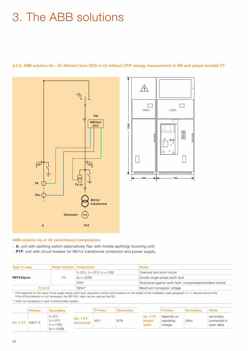
3.3.2. ABB solution 4b – DI different from DDG in LV without UTIF energy measurement in MV and phase toroidal CT
MV/LVtransformer
Generator
ABB solution 4a or 4b switchboard composition
- A: unit with earthing switch (alternatively Rac with mobile earthing) incoming unit;- P1F: unit with circuit-breaker for MV/LV transformer protection and power supply.
Primary Secondary
No. 1 CT homopolar
40/1 67N
Primary Secondary
No. 3 CT 300/1-5
I> (51)I>> (51) I>>> (50)Io>> (50N)
Primary Secondary Notes
No. 3 VT phase/earth
depends on operating voltage
59Vo secondary connected in open delta
Type of relay Relay function Protections Notes
REF542plus PG
I> (51), I>> (51), I>>> (50) Overload and short-circuit
Io>> (50N) Double single-phase earth fault
67N* Directional against earth fault, compensated/isolated neutral
PI in LV 59Vo** Maximum homopolar voltage
* 67N depends on the value of the single-phase earth fault capacitive current and therefore on the length of the installation (see paragraph 2.1.1 General Device DG)If the 67N protection is not necessary, the REF 601 relay can be used as the DG.
** 59Vo not necessary in case of photovoltaic system.

29
P3 P3 P2
1950
375/500375/500 375/500
3.4. Diagrams – type of substation for generation bay power supply
Type 1 diagram
MV/LVtransformer
Generator

30
P2 Rac Rac P2
Rac P2
1950
375/500 375/500
1950
375/500
375/500 375/500
375/500
Type 2 diagram
Type 3 diagram
3. The ABB solutions

31

ABB S.p.A. Power Products DivisionUnità Operativa Sace-MVVia Friuli, 4I-24044 DalmineTel.: +39 035 6952 111Fax: +39 035 6952 874e-mail: [email protected]
www.abb.com
Contact us
1VC
P00
0294
- R
ev.
A,
en -
Tec
hnic
al g
uid
e -
2009
.10
(Act
ive
Use
rs C
EI 0
-16)
(gs)The data and illustrations are not binding. We
reserve the right to make changes in the course of technical development of the product.
Copyright 2009 ABB. All rights reserved.


![Active GPRS IO Users Manual v2[1]](https://img.pdfslide.us/doc/110x75/577ce6411a28abf103927bc4/active-gprs-io-users-manual-v21.jpg)