Embed Size (px)
Citation preview
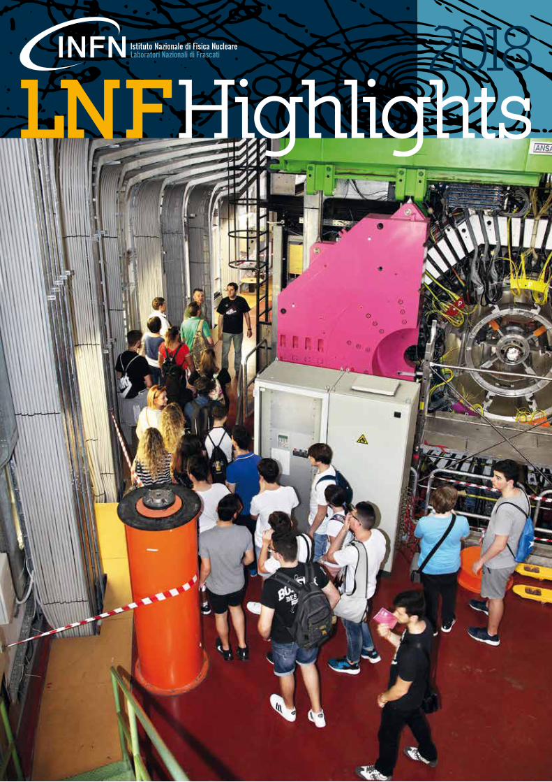
2018

2018One yearOf researchat Lnf
2 018 | 3
Scientific editor Paola GianottieditinG Paola Gianotti Lia SabatiniLayout & PrintinG tipolitografia Quatrini - Viterbo
coVer Photo: claudio federici
2018 has seen the ending of the operation of daΦne as a collider for experiments in Particle Physics. KLoe2 has successfully terminated its data taking at the end of
March, collecting the foreseen 6 fb-1. this represented a milestone in the history of the Lab, which for more than 60 years has built and operated accelerators devoted to High energy Physics. However, the Lab does not rest! Soon after this, the search for possible dark photons started at an upgraded Beam test facility with the PadMe experiment, and prepara-tions and setup of the machine are ongoing to run the SiddHarta2 de-tector, willing to study kaonic atoms.the Lab is preparing also its future: there are plans to make daΦne an international accelerator test facility, where future technological compo-nents can be tested in real beam conditions and where new ideas of small physics experiments can be performed. a workshop was held in decem-ber, gathering a lot of scientists and proposals.the euPraXia@SParc_LaB project, a beam-driven version of the larger euPraXia european design study, has completed its full-size version of the conceptual design report, which will represent a substantial part of the fi-nal euPraXia H2020 design Study report to be delivered to the european commission by the end of 2019. Here the ambition is to bring such an infra-structure of excellence in future technologies for accelerators to frascati.ideas on new machines, partially with a Lnf “imprinting”, are undergoing
scrutiny, such as the possibility of building a muon collider starting from high-energy positrons hitting a thin target. the option is fascinating, although extremely challenging. the work of an international team led by Lnf machine physicists will tell us if the option is doable.a long list of outreach activities has characterized 2018: open day, public lectures, matinees of science, training of High School students and teachers, etc…, with nearly 9000 people visiting the premises. the Visitor centre is fully operational, with a regular schedule of public visits. the efforts done on technological transfer start to show effects: regione Lazio has granted a rel-evant economic support for a Laboratory (Latino), opened for access to local industries active in accelerator technologies.a large set of staff has been hired in 2018. this is vital for the Laboratory, given the many new long-term projects ongoing. the whole Lab team must be acknowledged for its outstanding role in achieving these results. to them all, my warmest and deepest thanks.
ForewordPierluigi CampanaLnf director
2 018 | 54 | L n f h i g h l i g h t s
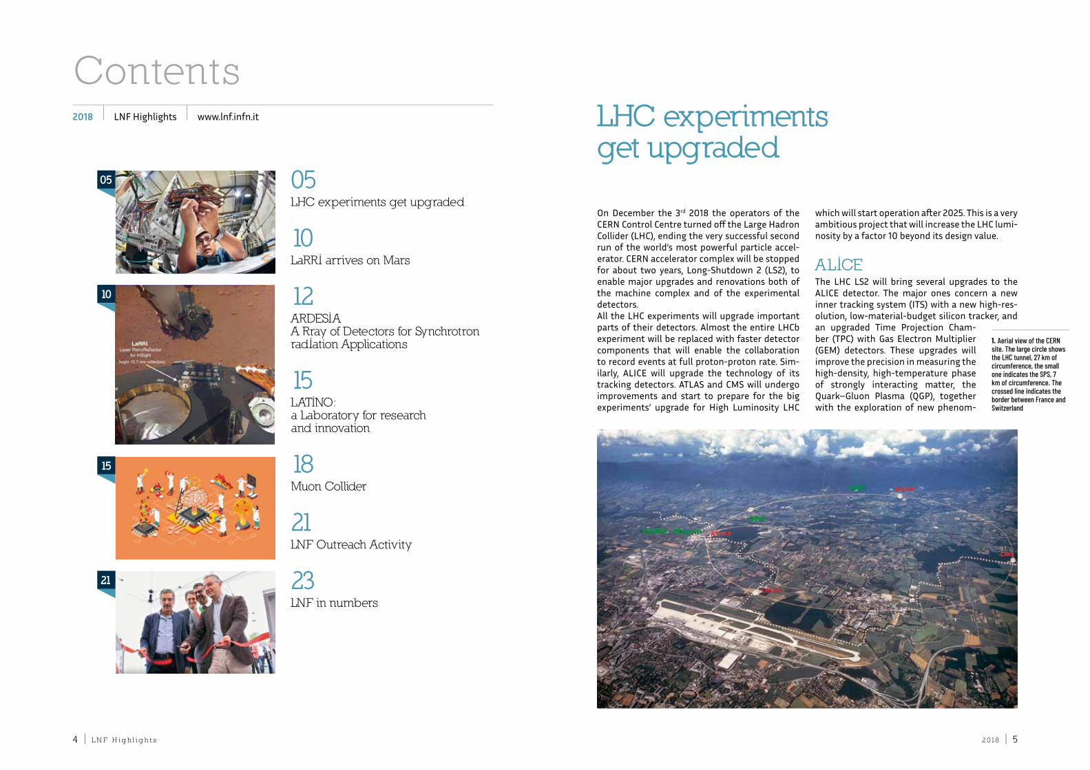
on december the 3rd 2018 the operators of the cern control centre turned off the Large Hadron collider (LHc), ending the very successful second run of the world’s most powerful particle accel-erator. cern accelerator complex will be stopped for about two years, Long-Shutdown 2 (LS2), to enable major upgrades and renovations both of the machine complex and of the experimental detectors.all the LHc experiments will upgrade important parts of their detectors. almost the entire LHcb experiment will be replaced with faster detector components that will enable the collaboration to record events at full proton-proton rate. Sim-ilarly, aLice will upgrade the technology of its tracking detectors. atLaS and cMS will undergo improvements and start to prepare for the big experiments’ upgrade for High Luminosity LHc
which will start operation after 2025. this is a very ambitious project that will increase the LHc lumi-nosity by a factor 10 beyond its design value.
ALICEthe LHc LS2 will bring several upgrades to the aLice detector. the major ones concern a new inner tracking system (itS) with a new high-res-olution, low-material-budget silicon tracker, and an upgraded time Projection cham-ber (tPc) with Gas electron Multiplier (GeM) detectors. these upgrades will improve the precision in measuring the high-density, high-temperature phase of strongly interacting matter, the Quark–Gluon Plasma (QGP), together with the exploration of new phenom-
LHC experiments get upgraded
1. Aerial view of the CERN site. The large circle shows the LHC tunnel, 27 km of circumference, the small one indicates the SPS, 7 km of circumference. The crossed line indicates the border between France and Switzerland
contentsLnf Highlights www.lnf.infn.it2018
05Lhc experiments get upgraded
10LarrI arrives on Mars
12arDesIaa rray of Detectors for synchrotronradIation applications
15LatInO: a Laboratory for research and innovation
18Muon collider
21Lnf Outreach activity
23Lnf in numbers
05
10
15
21
2 018 | 76 | L n f h i g h l i g h t s
ena in Quantum chromodynamics (Qcd). aLice is preparing for an interaction rate of lead ions dur-ing the LHc run 3 around 50 kHz, corresponding to an instantaneous luminosity of 6 × 1027 cm–2 s–1. this will enable aLice to accumulate 10 times more integrated luminosity (more than 10 nb–1) and a data sample 100 times larger than what has been obtained so far. the new aLice itS is an all-pixel silicon tracker based on cMoS monolithic active pixel sensor (MaPS) technology. in MaPS technology, both the sensor for charge collection and the readout cir-cuit for digitisation are hosted in the same piece of silicon instead of being bump-bonded togeth-er. the chip developed by aLice is called aLPide and uses a 180 nm cMoS process provided by towerJazz. With this chip, the silicon material budget per layer is reduced by a factor of 7 com-
pared to the present itS. the aLPide chip is 15 × 30 mm2 in area and contains more than half a million pixels organ-ised in 1024 columns by 512 rows. it has low power consumption (< 40 mW/
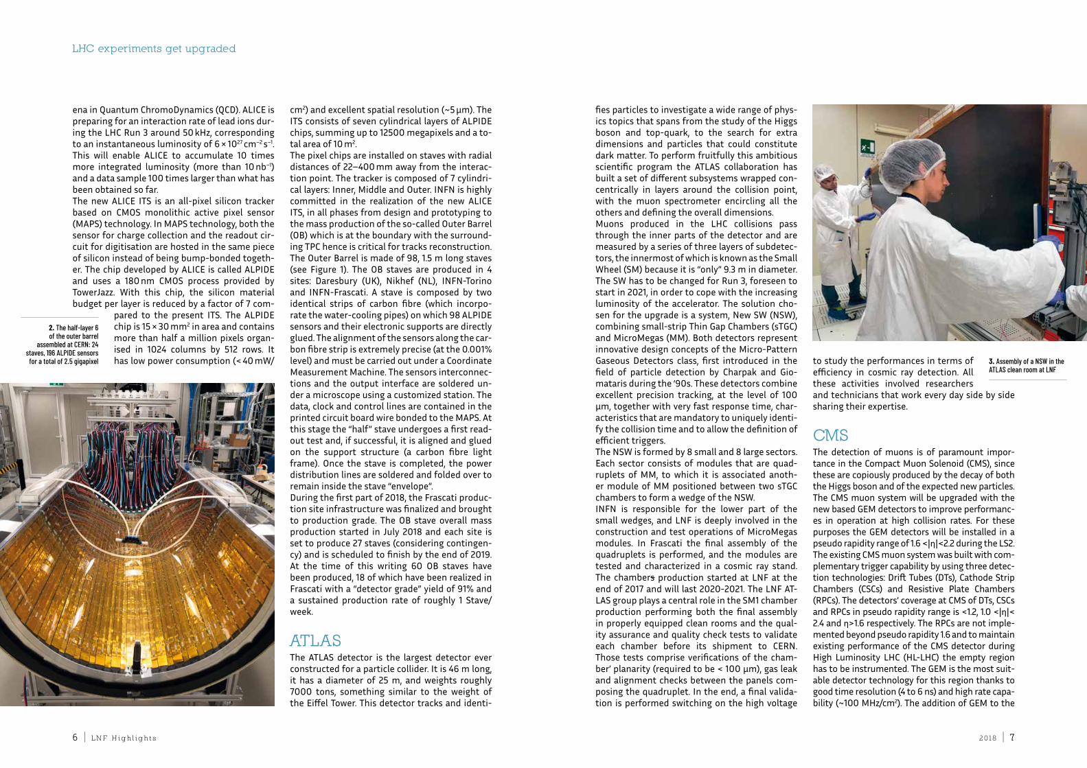
cm2) and excellent spatial resolution (~5 μm). the itS consists of seven cylindrical layers of aLPide chips, summing up to 12500 megapixels and a to-tal area of 10 m2. the pixel chips are installed on staves with radial distances of 22–400 mm away from the interac-tion point. the tracker is composed of 7 cylindri-cal layers: inner, Middle and outer. infn is highly committed in the realization of the new aLice itS, in all phases from design and prototyping to the mass production of the so-called outer Barrel (oB) which is at the boundary with the surround-ing tPc hence is critical for tracks reconstruction. the outer Barrel is made of 98, 1.5 m long staves (see figure 1). the oB staves are produced in 4 sites: daresbury (uK), nikhef (nL), infn-torino and infn-frascati. a stave is composed by two identical strips of carbon fibre (which incorpo-rate the water-cooling pipes) on which 98 aLPide sensors and their electronic supports are directly glued. the alignment of the sensors along the car-bon fibre strip is extremely precise (at the 0.001% level) and must be carried out under a coordinate Measurement Machine. the sensors interconnec-tions and the output interface are soldered un-der a microscope using a customized station. the data, clock and control lines are contained in the printed circuit board wire bonded to the MaPS. at this stage the “half” stave undergoes a first read-out test and, if successful, it is aligned and glued on the support structure (a carbon fibre light frame). once the stave is completed, the power distribution lines are soldered and folded over to remain inside the stave “envelope”.during the first part of 2018, the frascati produc-tion site infrastructure was finalized and brought to production grade. the oB stave overall mass production started in July 2018 and each site is set to produce 27 staves (considering contingen-cy) and is scheduled to finish by the end of 2019. at the time of this writing 60 oB staves have been produced, 18 of which have been realized in frascati with a “detector grade” yield of 91% and a sustained production rate of roughly 1 Stave/week.
ATLASthe atLaS detector is the largest detector ever constructed for a particle collider. it is 46 m long, it has a diameter of 25 m, and weights roughly 7000 tons, something similar to the weight of the eiffel tower. this detector tracks and identi-
fies particles to investigate a wide range of phys-ics topics that spans from the study of the Higgs boson and top-quark, to the search for extra dimensions and particles that could constitute dark matter. to perform fruitfully this ambitious scientific program the atLaS collaboration has built a set of different subsystems wrapped con-centrically in layers around the collision point, with the muon spectrometer encircling all the others and defining the overall dimensions.Muons produced in the LHc collisions pass through the inner parts of the detector and are measured by a series of three layers of subdetec-tors, the innermost of which is known as the Small Wheel (SM) because it is “only” 9.3 m in diameter. the SW has to be changed for run 3, foreseen to start in 2021, in order to cope with the increasing luminosity of the accelerator. the solution cho-sen for the upgrade is a system, new SW (nSW), combining small-strip thin Gap chambers (stGc) and MicroMegas (MM). Both detectors represent innovative design concepts of the Micro-Pattern Gaseous detectors class, first introduced in the field of particle detection by charpak and Gio-mataris during the ‘90s. these detectors combine excellent precision tracking, at the level of 100 μm, together with very fast response time, char-acteristics that are mandatory to uniquely identi-fy the collision time and to allow the definition of efficient triggers. the nSW is formed by 8 small and 8 large sectors. each sector consists of modules that are quad-ruplets of MM, to which it is associated anoth-er module of MM positioned between two stGc chambers to form a wedge of the nSW.infn is responsible for the lower part of the small wedges, and Lnf is deeply involved in the construction and test operations of MicroMegas modules. in frascati the final assembly of the quadruplets is performed, and the modules are tested and characterized in a cosmic ray stand. the chambers production started at Lnf at the end of 2017 and will last 2020-2021. the Lnf at-LaS group plays a central role in the SM1 chamber production performing both the final assembly in properly equipped clean rooms and the qual-ity assurance and quality check tests to validate each chamber before its shipment to cern. those tests comprise verifications of the cham-ber’ planarity (required to be < 100 μm), gas leak and alignment checks between the panels com-posing the quadruplet. in the end, a final valida-tion is performed switching on the high voltage
to study the performances in terms of efficiency in cosmic ray detection. all these activities involved researchers and technicians that work every day side by side sharing their expertise.
CMSthe detection of muons is of paramount impor-tance in the compact Muon Solenoid (cMS), since these are copiously produced by the decay of both the Higgs boson and of the expected new particles. the cMS muon system will be upgraded with the new based GeM detectors to improve performanc-es in operation at high collision rates. for these purposes the GeM detectors will be installed in a pseudo rapidity range of 1.6 <|η|<2.2 during the LS2.the existing cMS muon system was built with com-plementary trigger capability by using three detec-tion technologies: drift tubes (dts), cathode Strip chambers (cScs) and resistive Plate chambers (rPcs). the detectors’ coverage at cMS of dts, cScs and rPcs in pseudo rapidity range is <1.2, 1.0 <|η|< 2.4 and η>1.6 respectively. the rPcs are not imple-mented beyond pseudo rapidity 1.6 and to maintain existing performance of the cMS detector during High Luminosity LHc (HL-LHc) the empty region has to be instrumented. the GeM is the most suit-able detector technology for this region thanks to good time resolution (4 to 6 ns) and high rate capa-bility (~100 MHz/cm2). the addition of GeM to the
2. The half-layer 6 of the outer barrel
assembled at CERN: 24 staves, 196 ALPIDE sensors
for a total of 2.5 gigapixel
LHC experiments get upgraded
3. Assembly of a NSW in the ATLAS clean room at LNF
2 018 | 98 | L n f h i g h l i g h t s
LHC experiments get upgraded
cMS muon system will improve the muon momen-tum resolution, reduce the global muon trigger rate, assure a high muon reconstruction efficiency, and increase offline muon identification coverage.at the proposed GeM installation region, a very high flux of particles (neutrons, photons, charged particles) is expected, the neutron flux is ~1.5x10⁵
Hz/cm2 when LHc runs at luminosity 5x1034 cm-2s-1. for neutrons, the GeM detectors’ discharge prob-ability is negligible therefore the GeM can work safely in such environment. the GeM detectors have proven their capability to run under LHc re-quirements (rate capability 10 kHz/cm2, efficien-cy >97%, time resolution ~10 ns, gain uniform-ity ~15%) of the cMS experiment in high particle background. the GeM detectors planned to be installed in cMS during LS2 are named Ge1/1, standing for GeM endcap station n.1, ring n.1. a total of 144 Ge1/1 chambers will be installed at two forward muon stations, i.e. positive and neg-ative sides of the cMS symmetrically. the Ge1/1 production started in 2017 and continued in 2018. each chamber is approximately 110 cm long and 60 cm wide and is based on the triple-GeM geom-etry (3-1-2-1). the cMS frascati group plays a cen-tral role in all this activity having a member of the group in charge as general production supervisor, with the responsibility to oversee the production in the other assembly sites (infn Bari, florida in-stitute of technology and cern). frascati itself is
a production site of Ge1/1 chambers. in the frascati cMS laboratory, the cham-bers are assembled and tested under several quality control setups, required
to accept a chamber for the final installation in the experiment. Quality control tests performed in frascati include gas leak, HV vs i characteris-tic curve, gain curve, gain mapping for uniformity. the cMS frascati Group has also the responsibil-ity of the installation and operation of a network of fiber Bragg Grating (fBG) optoelectronics tem-perature sensors mounted in each Ge1/1 chamber. the fBG sensors will provide a detailed map of the temperature gradient in the Ge1/1 region, and online monitoring.
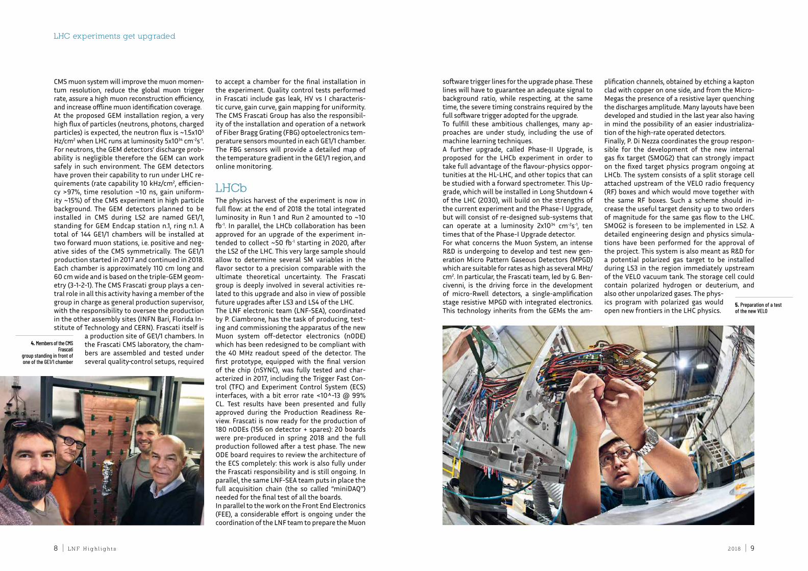
LHCbthe physics harvest of the experiment is now in full flow: at the end of 2018 the total integrated luminosity in run 1 and run 2 amounted to ~10 fb-1. in parallel, the LHcb collaboration has been approved for an upgrade of the experiment in-tended to collect ~50 fb-1 starting in 2020, after the LS2 of the LHc. this very large sample should allow to determine several SM variables in the flavor sector to a precision comparable with the ultimate theoretical uncertainty. the frascati group is deeply involved in several activities re-lated to this upgrade and also in view of possible future upgrades after LS3 and LS4 of the LHc.the Lnf electronic team (Lnf-Sea), coordinated by P. ciambrone, has the task of producing, test-ing and commissioning the apparatus of the new Muon system off-detector electronics (node) which has been redesigned to be compliant with the 40 MHz readout speed of the detector. the first prototype, equipped with the final version of the chip (nSync), was fully tested and char-acterized in 2017, including the trigger fast con-trol (tfc) and experiment control System (ecS) interfaces, with a bit error rate <10^-13 @ 99% cL. test results have been presented and fully approved during the Production readiness re-view. frascati is now ready for the production of 180 nodes (156 on detector + spares): 20 boards were pre-produced in spring 2018 and the full production followed after a test phase. the new ode board requires to review the architecture of the ecS completely: this work is also fully under the frascati responsibility and is still ongoing. in parallel, the same Lnf-Sea team puts in place the full acquisition chain (the so called “minidaQ’’) needed for the final test of all the boards.in parallel to the work on the front end electronics (fee), a considerable effort is ongoing under the coordination of the Lnf team to prepare the Muon
software trigger lines for the upgrade phase. these lines will have to guarantee an adequate signal to background ratio, while respecting, at the same time, the severe timing constrains required by the full software trigger adopted for the upgrade. to fulfill these ambitious challenges, many ap-proaches are under study, including the use of machine learning techniques.a further upgrade, called Phase-ii upgrade, is proposed for the LHcb experiment in order to take full advantage of the flavour-physics oppor-tunities at the HL-LHc, and other topics that can be studied with a forward spectrometer. this up-grade, which will be installed in Long Shutdown 4 of the LHc (2030), will build on the strengths of the current experiment and the Phase-i upgrade, but will consist of re-designed sub-systems that can operate at a luminosity 2x1034 cm-2s-1, ten times that of the Phase-i upgrade detector. for what concerns the Muon System, an intense r&d is undergoing to develop and test new gen-eration Micro Pattern Gaseous detectors (MPGd) which are suitable for rates as high as several MHz/cm2. in particular, the frascati team, led by G. Ben-civenni, is the driving force in the development of micro-rwell detectors, a single-amplification stage resistive MPGd with integrated electronics. this technology inherits from the GeMs the am-
plification channels, obtained by etching a kapton clad with copper on one side, and from the Micro-Megas the presence of a resistive layer quenching the discharges amplitude. Many layouts have been developed and studied in the last year also having in mind the possibility of an easier industrializa-tion of the high-rate operated detectors.finally, P. di nezza coordinates the group respon-sible for the development of the new internal gas fix target (SMoG2) that can strongly impact on the fixed target physics program ongoing at LHcb. the system consists of a split storage cell attached upstream of the VeLo radio frequency (rf) boxes and which would move together with the same rf boxes. Such a scheme should in-crease the useful target density up to two orders of magnitude for the same gas flow to the LHc. SMoG2 is foreseen to be implemented in LS2. a detailed engineering design and physics simula-tions have been performed for the approval of the project. this system is also meant as r&d for a potential polarized gas target to be installed during LS3 in the region immediately upstream of the VeLo vacuum tank. the storage cell could contain polarized hydrogen or deuterium, and also other unpolarized gases. the phys-ics program with polarized gas would open new frontiers in the LHc physics.
4. Members of the CMS Frascati
group standing in front of one of the GE1/1 chamber
5. Preparation of a test of the new VELO
2 018 | 1110 | L n f h i g h l i g h t s
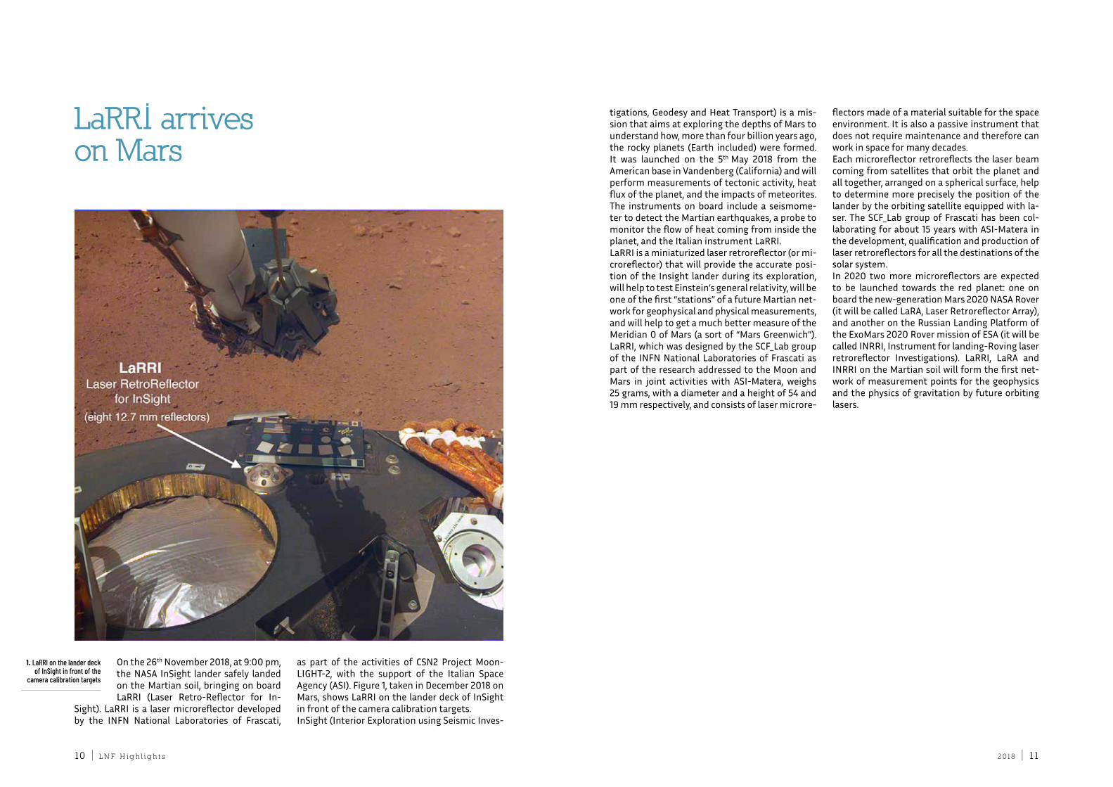
on the 26th november 2018, at 9:00 pm, the naSa inSight lander safely landed on the Martian soil, bringing on board Larri (Laser retro-reflector for in-
Sight). Larri is a laser microreflector developed by the infn national Laboratories of frascati,
as part of the activities of cSn2 Project Moon-LiGHt-2, with the support of the italian Space agency (aSi). figure 1, taken in december 2018 on Mars, shows Larri on the lander deck of inSight in front of the camera calibration targets.inSight (interior exploration using Seismic inves-
tigations, Geodesy and Heat transport) is a mis-sion that aims at exploring the depths of Mars to understand how, more than four billion years ago, the rocky planets (earth included) were formed. it was launched on the 5th May 2018 from the american base in Vandenberg (california) and will perform measurements of tectonic activity, heat flux of the planet, and the impacts of meteorites. the instruments on board include a seismome-ter to detect the Martian earthquakes, a probe to monitor the flow of heat coming from inside the planet, and the italian instrument Larri.Larri is a miniaturized laser retroreflector (or mi-croreflector) that will provide the accurate posi-tion of the insight lander during its exploration, will help to test einstein’s general relativity, will be one of the first “stations” of a future Martian net-work for geophysical and physical measurements, and will help to get a much better measure of the Meridian 0 of Mars (a sort of “Mars Greenwich”). Larri, which was designed by the Scf_Lab group of the infn national Laboratories of frascati as part of the research addressed to the Moon and Mars in joint activities with aSi-Matera, weighs 25 grams, with a diameter and a height of 54 and 19 mm respectively, and consists of laser microre-
flectors made of a material suitable for the space environment. it is also a passive instrument that does not require maintenance and therefore can work in space for many decades.each microreflector retroreflects the laser beam coming from satellites that orbit the planet and all together, arranged on a spherical surface, help to determine more precisely the position of the lander by the orbiting satellite equipped with la-ser. the Scf_Lab group of frascati has been col-laborating for about 15 years with aSi-Matera in the development, qualification and production of laser retroreflectors for all the destinations of the solar system.in 2020 two more microreflectors are expected to be launched towards the red planet: one on board the new-generation Mars 2020 naSa rover (it will be called Lara, Laser retroreflector array), and another on the russian Landing Platform of the exoMars 2020 rover mission of eSa (it will be called inrri, instrument for landing-roving laser retroreflector investigations). Larri, Lara and inrri on the Martian soil will form the first net-work of measurement points for the geophysics and the physics of gravitation by future orbiting lasers.
LaRRI arriveson Mars
1. LaRRI on the lander deck of InSight in front of the
camera calibration targets
2 018 | 1312 | L n f h i g h l i g h t s
the ARDESIA (ARray of DEtectors for Synchrotron radIation Applications) project, for the develop-ment of a new detection system for synchrotron radiation X-ray fluorescence (Xrf) and X-ray ab-sorption (XaS) measurements, based on arrays of Sdd (Silicon drift detector) with high energy res-olution and able to handle high count rates was approved in 2014 by the infn national Scientific committee V and started on the 1st of January 2015. the proposed duration of the project was three years, but a fourth year was asked to perform tests using synchrotron radiation. for this reason, in 2018 the ardeSia detector was successfully tested at the dXr1 soft X-ray beamline of the infn-Lnf daΦne-Light facility in february and at the BM08 “LiSa” crG beamline at eSrf (Grenoble - france) for about 6 months. taking into account the great results achieved, it is sure that the ardeSia project has been a very successful collaboration between the Politecnico di Milano, the daΦne-Light facility at the Lnf and tiPfa-fBK at trento [1,2]. ardeSia is a four-channel X-ray spectrometer based on Sdds, engineered in a finger-like structure
that gives the possibility to place it very near to the sample using a specific vac-uum-tight translating system (figure 1).the external tube has a diameter of 38
mm and is needed for protecting the detector and maintaining an internal static vacuum to prevent ice formation when the detector is cooled down to −40°c using a chiller and two Peltier cells. the ardeSia finger is closed with a vacuum window able to separate the high vacuum environment of the experimental chamber from the one of the detector and at the same time grants a high X-ray transmission in the energy range of interest. in the high-energy range a beryllium window can be used while in the soft X-ray region an aP5 poly-mer MoXteK window insures the needed high X-ray transmission. Beside the spectrometer, two external electronic systems, both realized at the Politecnico di Milano, needed to manage the power supply (teSLa) [2] and the cooling system (KraKatoa) [2] of ardeSia, make it a standalone and easily transportable system [2]. a monolithic 2x2 Sdds matrix, 450 μm thick, rep-resents the detection module of ardeSia. Hav-ing these Sdds full sideward depletion and small anode capacitance, independent from the active area, they are the ideal detectors for high-count rate applications. the fondazione Bruno Kessler (fBK -trento, italy) produces these SddS using a low-leakage manufacturing process. two 4-chan-nel detectors, having different pixel shapes, can
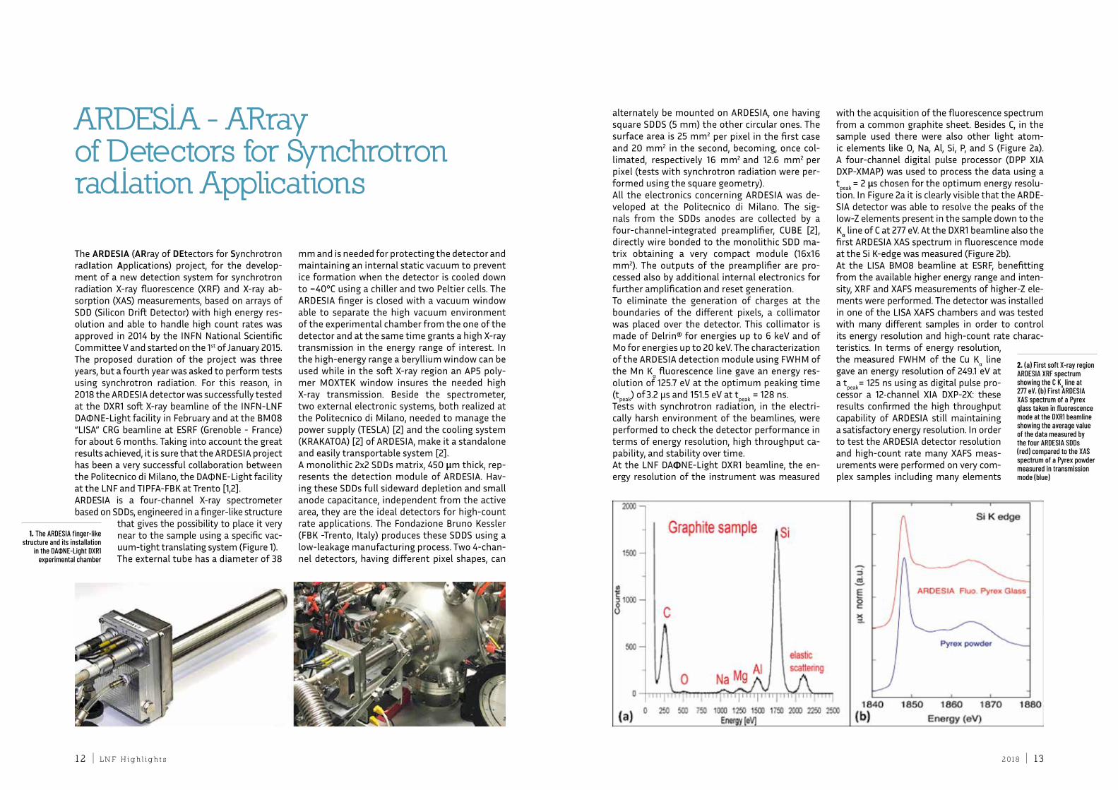
alternately be mounted on ardeSia, one having square SddS (5 mm) the other circular ones. the surface area is 25 mm2 per pixel in the first case and 20 mm2 in the second, becoming, once col-limated, respectively 16 mm2 and 12.6 mm2 per pixel (tests with synchrotron radiation were per-formed using the square geometry). all the electronics concerning ardeSia was de-veloped at the Politecnico di Milano. the sig-nals from the Sdds anodes are collected by a four-channel-integrated preamplifier, cuBe [2], directly wire bonded to the monolithic Sdd ma-trix obtaining a very compact module (16x16 mm2). the outputs of the preamplifier are pro-cessed also by additional internal electronics for further amplification and reset generation. to eliminate the generation of charges at the boundaries of the different pixels, a collimator was placed over the detector. this collimator is made of delrin® for energies up to 6 keV and of Mo for energies up to 20 keV. the characterization of the ardeSia detection module using fWHM of the Mn Kα fluorescence line gave an energy res-olution of 125.7 eV at the optimum peaking time (tpeak) of 3.2 μs and 151.5 eV at tpeak = 128 ns. tests with synchrotron radiation, in the electri-cally harsh environment of the beamlines, were performed to check the detector performance in terms of energy resolution, high throughput ca-pability, and stability over time. at the Lnf daΦne-Light dXr1 beamline, the en-ergy resolution of the instrument was measured
with the acquisition of the fluorescence spectrum from a common graphite sheet. Besides c, in the sample used there were also other light atom-ic elements like o, na, al, Si, P, and S (figure 2a). a four-channel digital pulse processor (dPP Xia dXP-XMaP) was used to process the data using a tpeak = 2 μs chosen for the optimum energy resolu-tion. in figure 2a it is clearly visible that the arde-Sia detector was able to resolve the peaks of the low-Z elements present in the sample down to the Kα line of c at 277 eV. at the dXr1 beamline also the first ardeSia XaS spectrum in fluorescence mode at the Si K-edge was measured (figure 2b).at the LiSa BM08 beamline at eSrf, benefitting from the available higher energy range and inten-sity, Xrf and XafS measurements of higher-Z ele-ments were performed. the detector was installed in one of the LiSa XafS chambers and was tested with many different samples in order to control its energy resolution and high-count rate charac-teristics. in terms of energy resolution, the measured fWHM of the cu Kα line gave an energy resolution of 249.1 eV at a tpeak= 125 ns using as digital pulse pro-cessor a 12‐channel Xia dXP-2X: these results confirmed the high throughput capability of ardeSia still maintaining a satisfactory energy resolution. in order to test the ardeSia detector resolution and high-count rate many XafS meas-urements were performed on very com-plex samples including many elements
ARDESIA - ARray of Detectors for Synchrotron radIation Applications
1. The ARDESIA finger-like structure and its installation
in the DAΦNE-Light DXR1 experimental chamber
2. (a) First soft X-ray region ARDESIA XRF spectrum showing the C Kα line at 277 eV. (b) First ARDESIA XAS spectrum of a Pyrex glass taken in fluorescence mode at the DXR1 beamline showing the average value of the data measured by the four ARDESIA SDDs (red) compared to the XAS spectrum of a Pyrex powder measured in transmission mode (blue)
2 018 | 1514 | L n f h i g h l i g h t s
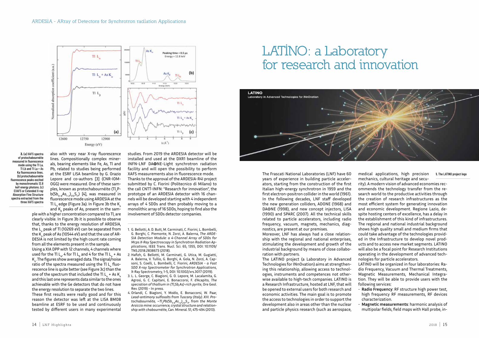
also with very near X-ray fluorescence lines. compositionally complex miner-als, bearing elements like fe, as, tl and Pb, related to studies being performed at the eSrf LiSa beamline by G. orazio Lepore and co-authors [3] (cnr-ioM-oGG) were measured. one of these sam-ples, known as protochabournéite (tl2P-b(Sb9–8as1–2)Σ10S17) [4], was measured in fluorescence mode using ardeSia at the tl L3 edge (figure 3a). in figure 3b the Kα and Kβ peaks of as, present in the sam-
ple with a higher concentration compared to tl, are clearly visible. in figure 3b it is possible to observe that, thanks to the energy resolution of ardeSia, the Lα peak of tl (10269 eV) can be separated from the Kα peak of as (10544 eV) and that the use of ar-deSia is not limited by the high count rate coming from all the elements present in the sample.using a Xia dPP with 12 channels, 4 channels where used for the tl Lα, 4 for tl Lβ and 4 for the tl Lα + as Kα. the figures show averaged data. the signal/noise ratio of the spectra measured using the tl Lα fluo-rescence line is quite better (see figure 3c) than the one of the spectrum that included the tl Lα + as Kα and this last one represents data similar to the ones achievable with the Ge detectors that do not have the energy resolution to separate the two lines. these first results were really good and for this reason the detector was left at the LiSa BM08 beamline at eSrf to be used and continuously tested by different users in many experimental
studies. from 2019 the ardeSia detector will be installed and used at the dXr1 beamline of the infn-Lnf daΦne-Light synchrotron radiation facility and will open the possibility to perform XafS measurements also in fluorescence mode.thanks to the approval of the ardeSia-r4i project submitted by c. fiorini (Politecnico di Milano) to the call cntt-infn: “research for innovation”, the prototype of an ardeSia detector with 16 chan-nels will be developed starting with 4 independent arrays of 4 Sdds and then probably moving to a monolithic array of 16 Sdds, hoping to find also the involvement of Sdds detector companies.
ARDESIA - ARray of Detectors for Synchrotron radIation Applications
3. (a) XAFS spectra of protochabournéite
measured in fluorescence mode using the Tl La,
Tl Lb and Tl La + As Ka fluorescence lines. (b) protochabournéite
fluorescence peaks excited by monochromatic 12.8 keV energy photons. (c)
EXAFS or Extended X-ray Absorption Fine Structure
spectra extracted from the three XAFS spectra
1. G. Bellotti, a. d. Butt, M. carminati, c. fiorini, L. Bombelli, G. Borghi, c. Piemonte, n. Zorzi, a. Balerna, The ARDE-SIA Detection Module: a 4-Channel Array of SDDs for Mcps X-Ray Spectroscopy in Synchrotron Radiation Ap-plications, ieee trans. nucl. Sci. 65, 1355, doi: 10.1109/tnS.2018.2838673 (2018).
2. Hafizh, G. Bellotti, M. carminati, G. utica, M. Gugiatti, a. Balerna, V. tullio, G. Borghi, a. Gola, n. Zorzi, a. cap-soni, S. coelli, L. Bombelli, c. fiorini, ARDESIA - a Fast SDD X-ray Spectrometer for Synchrotron Applications, X-ray Spectrometry, 1-5, doi: 10.1002/xrs.3017 (2019).
3. L. L. George, c. Biagioni, G. o. Lepore, M. Lacalamita, G. agrosì, G. c. capitani, e. Bonaccorsi, f. d’acapito, The speciation of thallium in (Tl,Sb,As)-rich pyrite, ore Geol. rev. (2019) - in press.
4. orlandi, c. Biagioni, y. Moëlo, e. Bonaccorsi, W. Paar, Lead-antimony sulfosalts from Tuscany (Italy). XIII. Pro-tochabournéite, ~Tl2Pb(Sb9-8As1-2)∑10S17, from the Monte Arsiccio mine: occurrence, crystal structure and relation-ship with chabournéite, can. Mineral. 51, 475-494 (2013).
the frascati national Laboratories (Lnf) have 60 years of experience in building particle acceler-ators, starting from the construction of the first italian high-energy synchrotron in 1959 and the first electron-positron collider in the world (1961). in the following decades, Lnf staff developed the new generation colliders, adone (1968) and daΦne (1998), and new concept injectors, LiSa (1990) and SParc (2007). all the technical skills related to particle accelerators, including radio frequency, vacuum, magnets, mechanics, diag-nostics, are present at our premises.Moreover, Lnf has always had a close relation-ship with the regional and national enterprises, stimulating the development and growth of the industrial background by means of close collabo-ration with partners.the Latino project (a Laboratory in advanced technologies for innovation) aims at strengthen-ing this relationship, allowing access to technol-ogies, instruments and competences not other-wise available to high-tech companies. Latino is a research infrastructure, hosted at Lnf, that will be opened to external users for both research and economic activities. the main goal is to promote the access to technologies in order to support the development also in areas other than the nuclear and particle physics research (such as aerospace,
medical applications, high precision mechanics, cultural heritage and secu-rity). a modern vision of advanced economies rec-ommends the technology transfer from the re-search world to the productive activities through the creation of research infrastructures as the most efficient system for generating innovation and economic development. regione Lazio, de-spite hosting centers of excellence, has a delay in the establishment of this kind of infrastructures. the regional and national industrial background shows high quality small and medium firms that could take advantage of the technologies provid-ed in the infrastructure to develop novel prod-ucts and to access new market segments. Latino will also be a focal point for research institutions operating in the development of advanced tech-nologies for particle accelerators.Latino will be organized in four laboratories: ra-dio frequency, Vacuum and thermal treatments, Magnetic Measurements, Mechanical integra-tion. they will be able to provide users with the following services: - Radio Frequency: rf structure high power test,
high frequency rf measurements, rf devices characterization.
- Magnetic measurements: harmonic analysis of multipolar fields, field maps with Hall probe, in-
LATINO: a Laboratory for research and innovation
1. The LATINO project logo
2 018 | 1716 | L n f h i g h l i g h t s
tegral magnetic field measurements and fidu-cialization, magnetic design of electromagnets.
- Vacuum and thermal treatments: ultra-high vacuum or controlled atmosphere thermal treatments, brazing in ultra-high vacuum, measurement of specific degassing of samples.
- Mechanical Integration: architectonic laser scanner, stereoscopic laser scanner, mechanical integration and space management.
the project has been stimulated by the public call “open research infrastructure” of regione Lazio, within Por feSr 2014-2020, that aims at the re-industrialization of the area. the planned roadmap of the project is organized in two main steps: a first phase (24 months of duration) devoted to the cre-ation of the infrastructure, followed by the opera-tional phase in which the new born infrastructure will start performing its activities. a detailed busi-ness plan, based on a market research, has been drawn up in order to evaluate the economic as-pects of the project. the project has been started
in July 2018; its overall budget is 2.5 M€, with a regional cofounding of 1.6 M€. during the first phase, now in progress, the Laboratories will be equipped with
top-level instrumentation, that will integrate the already existing tools. in particular, the list of in-struments that are going to be purchased within the project includes: - a X-band high power plant to test cavities up to
50 Hz repetition rate and 200 MW input power;- a network analyser to characterize microwave
devices up to 110 GHz;- a rotating coil for accurate magnetic field meas-
urements of multipoles;- a stretched wire bench for magnet characteri-
zation;- a degassing measurement system to character-
ize vacuum materials; - an ultra-high vacuum oven for thermal treat-
ments and brazing;- an environment laser scanner;- a stereoscopic laser scanner.civil engineering works have also been planned, aiming at improving and upgrading the state of the existing buildings that will host the laborato-ries. More in detail, the building number 38 (Mag-netic Measurements Laboratory) will be provided with a new system for magnet cooling. the ex-isting system shows indeed some critical points related to the age of the plant; the new system
will improve the efficiency and the reliability. the maintenance works also include the renewal of the floor and of the main doors.the building number 7 will become the central hub for the other Latino laboratories. the exper-imental hall for the rf laboratory will be enclosed in a new bunker, with the configuration required for the X band test; the bunker will be provided with all the necessary systems (access control, ventilation, lighting, fire-fighting system). the cooling system for the rf components will also be upgraded. the control room will be located next to the bunker. the ultra-high vacuum oven will be located in a dedicated area of the build-ing, together with the thermal treatment station, close to the clean room of the vacuum group. the Mechanical integration Laboratory will also have its workroom in the same building.
the organizational structure of Latino envisages the figure of a general manager responsible for the management and coordination; every labo-ratory will be led by an infn technologist with strong competences in the field. the technical personnel of the corresponding Service of the Lnf accelerator division will be involved to carry out the daily activities. thus, Latino will take full advantage of the structure and expertise of the accelerator division. also the administrative and secretariat services will be required to support the management of the infrastructure.Besides the scientific and technological issues, the inclusion in a large research insti-tute of an open-access technological infrastructure that provides services to the research and industrial community is one of the main challenges.
2. The logo used by Regione LAZIO for the “Open Research Infrastructure” public notice
2. A sketch of the degassingmeasurement system
3. The existing ultra-high vacuum oven
1. M. florio, S. forte, e. Sirtori, cost-Benefit analysis of the Large Hadron collider to 2025 and Beyond, http://arxiv.org/pdf/1507.05638v1.pdf (2015)
2. eucard2 study group, applications of Particle accel-erators in europe, http://apae.ific.uv.es/apae/wp-con-tent/uploads/2015/04/eucard_applications-of-ac-celerators-2017.pdf (2015)
3. oxford economics, the economic impact of physics research in uK: Mri scanners case Study, http://www.stfc.ac.uk/files/the-economic-impact-of-physics-re-search-in-the-uk/ (2012)
4. institute of Physics, uK Physics research - driving innovation and Growth, https://www.iop.org/publica-tions/iop/2014/file_63111.pdf (2014)
5. Società italiana di fisica, the impact of Physics on the italian economics - final report by deloitte, https://www.sif.it/static/Sif/resources/public/files/re-port_2014/Sif-final-report.pdf (2014)
6. r. crescenzi, S. iammarino, a. rodríguez-Pose – Multi-nazionali, imprese Locali e Sviluppo economico nella regione Lazio (Luglio 2016)
7. Banca d’italia: roma. economie regionali. L’economia del Lazio. (2015)
8. Banca d’italia: roma. economie regionali. L’economia del Lazio. (2016)
9. http://www.lazioinnova.it/bandi-post/sostegno-al-le-infrastrutture-aperte-la-ricerca/
10. http://latino.lnf.infn.it/
LATINO: a Laboratory for research and innovation
2 018 | 1918 | L n f h i g h l i g h t s
different scenarios are being assessed to define the future of experimental particle physics after the full exploitation of the LHc potential. one of the envisaged possibilities is to explore the feasi-bility of a high energy muon collider, namely with a view to a high luminosity Higgs-factory. Many studies have been carried out to design a high rate muon source driven by K/π decay produced by proton beams on a target. despite the relative high intensity muon bunches produced in this scheme, the generated normalized 6d emittance is very large. to obtain the required luminosity the muon beam must be cooled very rapidly ow-ing to their short decay time. therefore, in this hypothesis, an innovative cooling scheme (ioniza-tion cooling) must be introduced with very high efficiency. to overcome this difficulty, a new muon gener-ation scheme was suggested in the framework of the Lnf LeMMa proposal [1]. in this new ap-proach muons are generated by a positron beam impinging on a solid or liquid target. using the
reaction e++e− → μ++μ− in a center of mass ener-gy just above threshold, it is possible to generate very collimated muon beams thanks to the Lor-entz boost. this makes it possible to produce low emittance muons that, coupled with nanobeam collision schemes [2] at very low beta function in the iP, provide high luminosity also with a relative low bunch population. nevertheless, the low value of the cross section (max 1 μb) does not make pos-sible to produce the required 109 μ/bunch popu-lation in a single passage in a target taking into account a reasonable positron beam intensity. according to the Liouville theorem, the recombi-nation of different beams of the same charge is not possible under Hamiltonian forces without in-creasing the beam phase space, therefore the only possible scheme envisages the production of the full intensity muon bunches in multiple collisions on targets where the “producing” positron and the “produced” muon bunches are physically mixed in the same phase space. in this way, each passage of the positron beam in the target produces a new
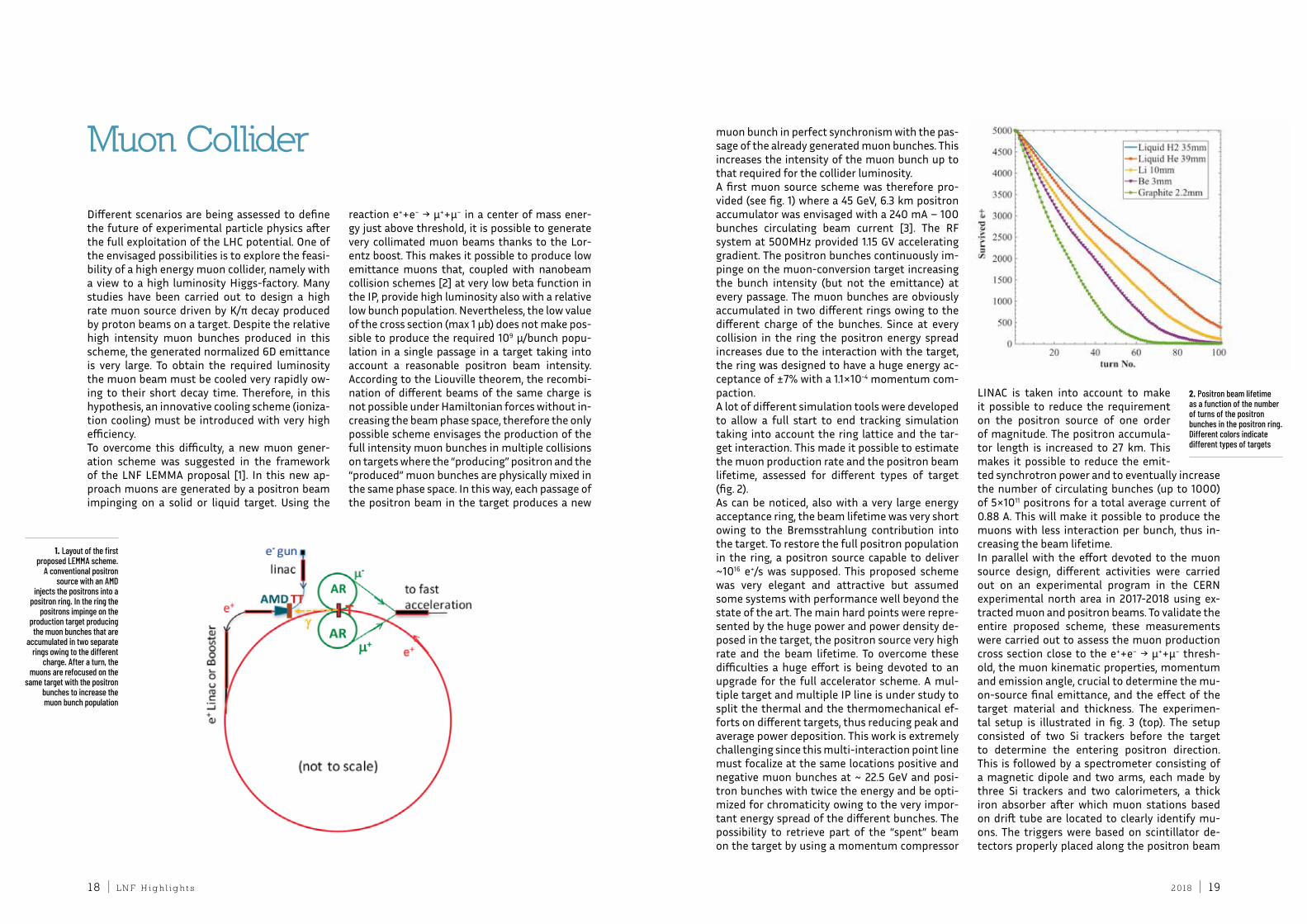
muon bunch in perfect synchronism with the pas-sage of the already generated muon bunches. this increases the intensity of the muon bunch up to that required for the collider luminosity. a first muon source scheme was therefore pro-vided (see fig. 1) where a 45 GeV, 6.3 km positron accumulator was envisaged with a 240 ma – 100 bunches circulating beam current [3]. the rf system at 500MHz provided 1.15 GV accelerating gradient. the positron bunches continuously im-pinge on the muon-conversion target increasing the bunch intensity (but not the emittance) at every passage. the muon bunches are obviously accumulated in two different rings owing to the different charge of the bunches. Since at every collision in the ring the positron energy spread increases due to the interaction with the target, the ring was designed to have a huge energy ac-ceptance of ±7% with a 1.1×10⁻⁴ momentum com-paction. a lot of different simulation tools were developed to allow a full start to end tracking simulation taking into account the ring lattice and the tar-get interaction. this made it possible to estimate the muon production rate and the positron beam lifetime, assessed for different types of target (fig. 2).as can be noticed, also with a very large energy acceptance ring, the beam lifetime was very short owing to the Bremsstrahlung contribution into the target. to restore the full positron population in the ring, a positron source capable to deliver ~1016 e+/s was supposed. this proposed scheme was very elegant and attractive but assumed some systems with performance well beyond the state of the art. the main hard points were repre-sented by the huge power and power density de-posed in the target, the positron source very high rate and the beam lifetime. to overcome these difficulties a huge effort is being devoted to an upgrade for the full accelerator scheme. a mul-tiple target and multiple iP line is under study to split the thermal and the thermomechanical ef-forts on different targets, thus reducing peak and average power deposition. this work is extremely challenging since this multi-interaction point line must focalize at the same locations positive and negative muon bunches at ~ 22.5 GeV and posi-tron bunches with twice the energy and be opti-mized for chromaticity owing to the very impor-tant energy spread of the different bunches. the possibility to retrieve part of the “spent” beam on the target by using a momentum compressor
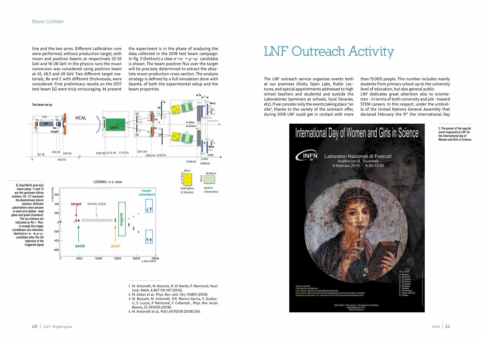
Linac is taken into account to make it possible to reduce the requirement on the positron source of one order of magnitude. the positron accumula-tor length is increased to 27 km. this makes it possible to reduce the emit-ted synchrotron power and to eventually increase the number of circulating bunches (up to 1000) of 5×10¹¹ positrons for a total average current of 0.88 a. this will make it possible to produce the muons with less interaction per bunch, thus in-creasing the beam lifetime. in parallel with the effort devoted to the muon source design, different activities were carried out on an experimental program in the cern experimental north area in 2017-2018 using ex-tracted muon and positron beams. to validate the entire proposed scheme, these measurements were carried out to assess the muon production cross section close to the e++e− → μ++μ− thresh-old, the muon kinematic properties, momentum and emission angle, crucial to determine the mu-on-source final emittance, and the effect of the target material and thickness. the experimen-tal setup is illustrated in fig. 3 (top). the setup consisted of two Si trackers before the target to determine the entering positron direction. this is followed by a spectrometer consisting of a magnetic dipole and two arms, each made by three Si trackers and two calorimeters, a thick iron absorber after which muon stations based on drift tube are located to clearly identify mu-ons. the triggers were based on scintillator de-tectors properly placed along the positron beam
Muon Collider
2. Positron beam lifetime as a function of the number of turns of the positron bunches in the positron ring. Different colors indicate different types of targets
1. Layout of the first proposed LEMMA scheme.
A conventional positron source with an AMD
injects the positrons into a positron ring. In the ring the
positrons impinge on the production target producing the muon bunches that are
accumulated in two separate rings owing to the different
charge. After a turn, the muons are refocused on the
same target with the positron bunches to increase the muon bunch population
2 018 | 212 0 | L n f h i g h l i g h t s
line and the two arms. different calibration runs were performed, without production target, with muon and positron beams at respectively 22-32 GeV and 16-28 GeV. in the physics runs the muon conversion was considered using positron beam at 45, 46.5 and 49 GeV. two different target ma-terials, Be and c with different thicknesses, were considered. first preliminary results on the 2017 test beam [4] were truly encouraging. at present
the experiment is in the phase of analyzing the data collected in the 2018 test beam campaign. in fig. 3 (bottom) a clear e++e− → μ++μ− candidate is shown. the beam positron flux over the target will be precisely determined to extract the abso-lute muon production cross section. the analysis strategy is defined by a full simulation done with Geant4, of both the experimental setup and the beam properties.
1. M. antonelli, M. Boscolo, r. di nardo, P. raimondi, nucl. instr. Meth. a 807 101-107 (2016).
2. M. Zobov et al., Phys. rev. Lett. 104, 174801 (2010).3. M. Boscolo, M. antonelli, o.r. Blanco-Garcia, S. Guiduc-
ci, S. Liuzzo, P. raimondi, f. collamati , Phys. rev. accel. Beams, 21, 061005 (2018).
4. M. antonelli et al., PoS LHcP2018 (2018) 256.
T1
S1
T2VP
Betarget
220C0
MBPL
C2
C3
C6
C7
C4
C5
S2
S3
C1
Mu2
Mu1
86.86cm30
cm
11.5
*3cm
0
1573.79 1773.79
40cm
lead-glass(3 blocks)
quartz cherenkov
460.93
441.63 549.9382.78
HCAL9
10
2025
30
31
32
33 35
34 36
37
4342
41
4645 44
52
5161
62
e-/mu-e+/mu+
1995.43 2125.43
11.518
2cm
87.4
3839
3°
47.8+2.2+2.2
24841492.93 1873.93
40
8.718
30.5
2348.662388.66
2394
4
55.6+2.2+2.2
VERSA
HORSA
Mu3Mu4
Mu1
Mu2
4
63
64
S4
S5
4
274.8
T1
S1
T2VP
Betarget
220C0
MBPL
C2
C3
C6
C7
C4
C5
S2
S3
C1
Mu2
Mu1
86.86cm
30cm
11.5
*3cm
0
1573.79 1773.79
40cm
lead-glass(3 blocks)
quartz cherenkov
460.93
441.63 549.9382.78
HCAL9
10
2025
30
31
32
33 35
34 36
37
4342
41
4645 44
52
5161
62
e-/mu-e+/mu+
1995.43 2125.43
11.518
2cm
87.4
3839
3°
47.8+2.2+2.2
24841492.93 1873.93
40
8.718
30.5
2348.66 2388.662394
4
55.6+2.2+2.2
VERSA
HORSA
Mu3Mu4
Mu1
Mu2
4
63
64
S4
S5
4
274.8
LEMMA: x-z view
x ax
is (m
m)
z axis (mm)
3. (top) North area test beam setup. T1 and T2
are the upstream silicon stations. C0 - C7 represent
the downstream silicon stations. Different
calorimeters were present in each arm (yellow - lead
glass and green Cerenkov). The mu stations are
indicated as Mu 1 - Mu4. In orange the trigger
scintillators are indicated. (bottom) e+-e− → μ+-μ−
candidate after the full selection of the triggered signal
Test beam set up
the Lnf outreach service organizes events both at our premises (Visits, open Labs, Public Lec-tures, and special appointments addressed to high school teachers and students) and outside the Laboratories (seminars at schools, local libraries, etc). if we consider only the events taking place “on site”, thanks to the variety of the outreach offer, during 2018 Lnf could get in contact with more
than 15.000 people. this number includes mainly students from primary school up to the university level of education, but also general public. Lnf dedicates great attention also to orienta-tion - in terms of both university and job - toward SteM careers. in this respect, under the umbrel-la of the united nations General assembly that declared february the 9th the international day
LNF Outreach Activity
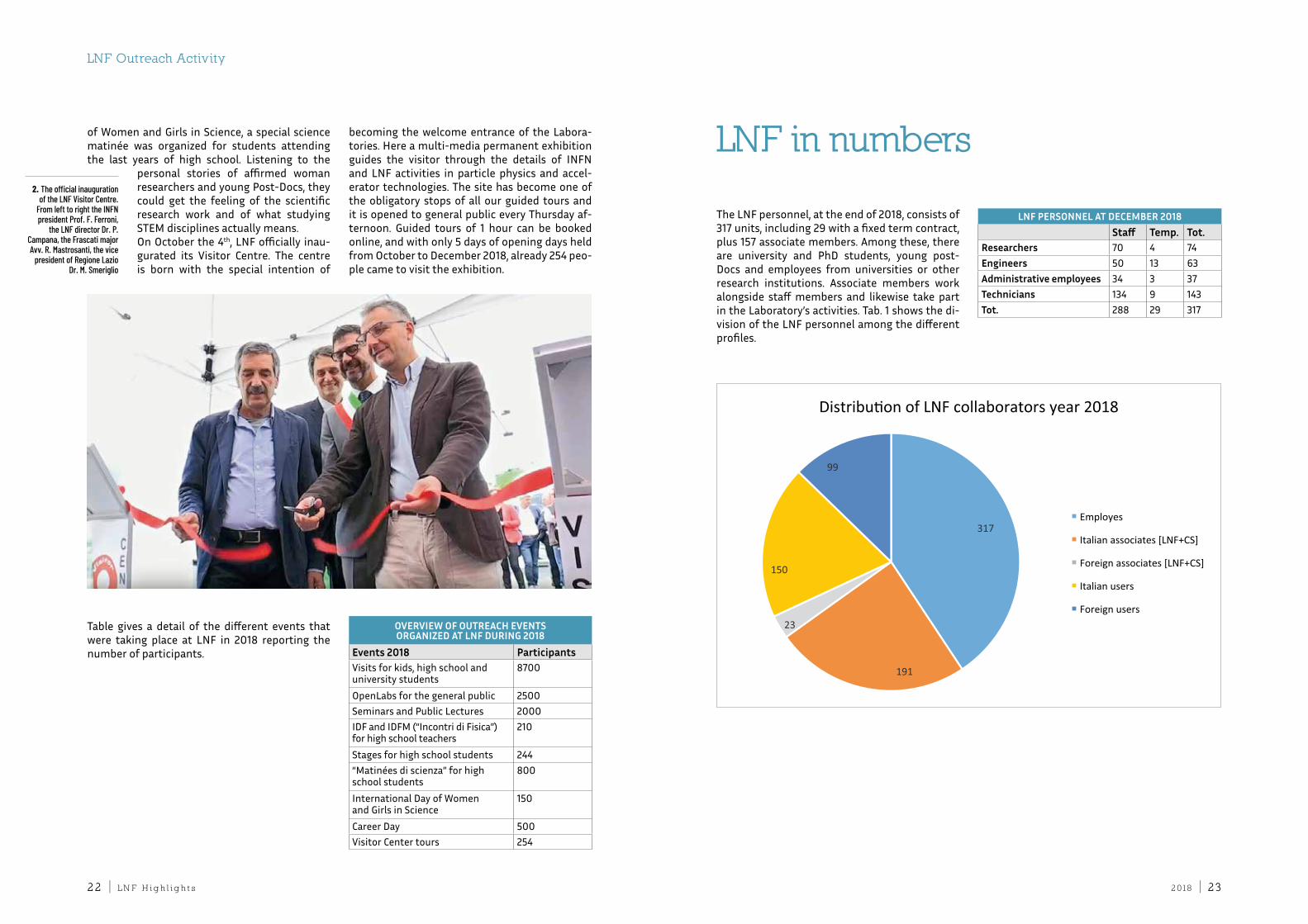
1. The poster of the special event organized at LNF for the International day of Women and Girls in Science
Muon Collider
2 018 | 232 2 | L n f h i g h l i g h t s
of Women and Girls in Science, a special science matinée was organized for students attending the last years of high school. Listening to the
personal stories of affirmed woman researchers and young Post-docs, they could get the feeling of the scientific research work and of what studying SteM disciplines actually means.on october the 4th, Lnf officially inau-gurated its Visitor centre. the centre is born with the special intention of
becoming the welcome entrance of the Labora-tories. Here a multi-media permanent exhibition guides the visitor through the details of infn and Lnf activities in particle physics and accel-erator technologies. the site has become one of the obligatory stops of all our guided tours and it is opened to general public every thursday af-ternoon. Guided tours of 1 hour can be booked online, and with only 5 days of opening days held from october to december 2018, already 254 peo-ple came to visit the exhibition.
OVERVIEw OF OutREACh EVEntSORgAnIzED At LnF DuRIng 2018
Events 2018 ParticipantsVisits for kids, high school and university students
8700
openLabs for the general public 2500Seminars and Public Lectures 2000idf and idfM (“incontri di fisica”) for high school teachers
210
Stages for high school students 244“Matinées di scienza” for high school students
800
international day of Women and Girls in Science
150
career day 500Visitor center tours 254
2. The official inauguration of the LNF Visitor Centre.
From left to right the INFN president Prof. F. Ferroni,
the LNF director Dr. P. Campana, the Frascati major Avv. R. Mastrosanti, the vice
president of Regione Lazio Dr. M. Smeriglio
table gives a detail of the different events that were taking place at Lnf in 2018 reporting the number of participants.
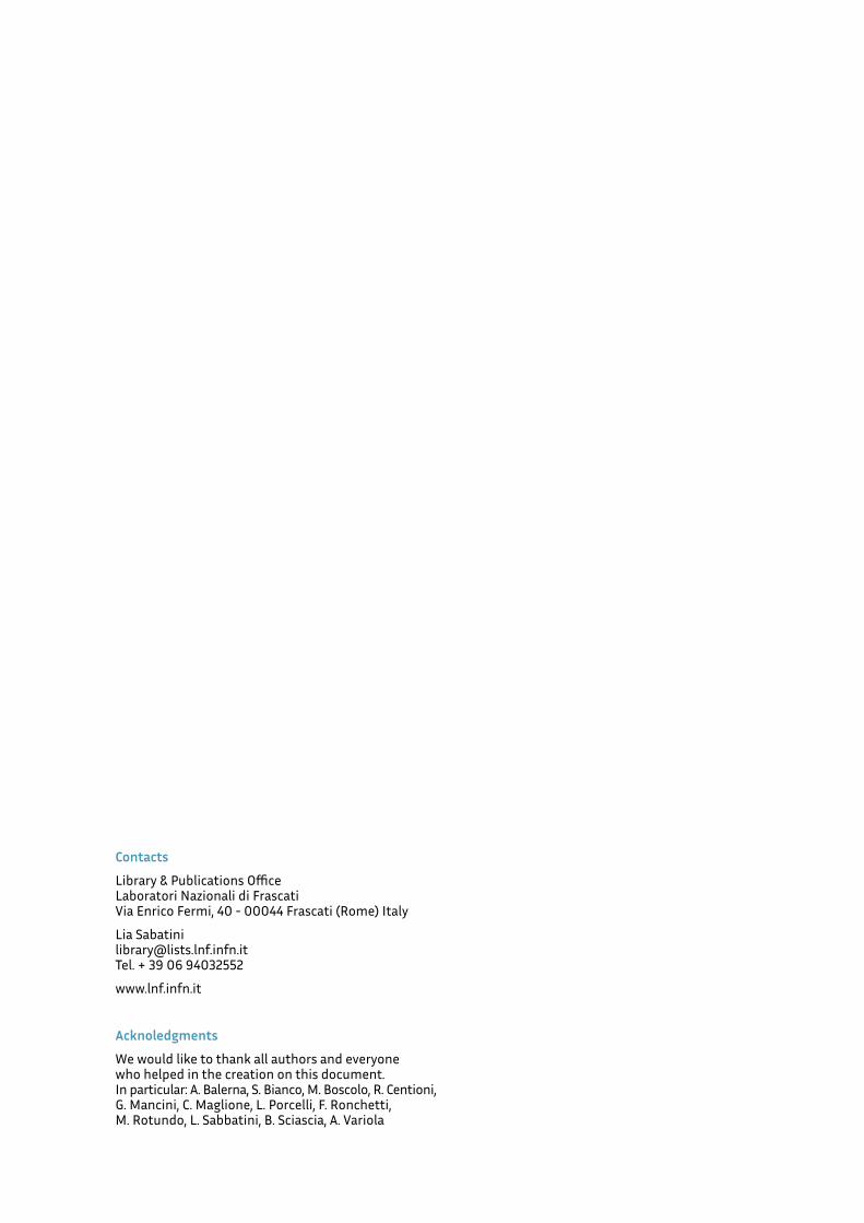
the Lnf personnel, at the end of 2018, consists of 317 units, including 29 with a fixed term contract, plus 157 associate members. among these, there are university and Phd students, young post-docs and employees from universities or other research institutions. associate members work alongside staff members and likewise take part in the Laboratory’s activities. tab. 1 shows the di-vision of the Lnf personnel among the different profiles.
LnF PERSOnnEL At DECEMbER 2018Staff temp. tot.
Researchers 70 4 74Engineers 50 13 63Administrative employees 34 3 37technicians 134 9 143tot. 288 29 317
LNF in numbers
LNF Outreach Activity
Contacts
Library & Publications office Laboratori nazionali di frascati Via enrico fermi, 40 - 00044 frascati (rome) italy
Lia Sabatini [email protected] tel. + 39 06 94032552
www.lnf.infn.it
Acknoledgments
We would like to thank all authors and everyone who helped in the creation on this document. in particular: a. Balerna, S. Bianco, M. Boscolo, r. centioni, G. Mancini, c. Maglione, L. Porcelli, f. ronchetti, M. rotundo, L. Sabbatini, B. Sciascia, a. Variola