Embed Size (px)
Citation preview
EcoGun 910Manual Air Spray Gun Gravity-Feed
MSG00003EN, V06
N36200003Vwww.durr.com
Operation manual
Information about the documentThis document describes the correct han-dling of the product.
Read the document prior to every activity.Prepare the document for the application.Pass on the product only together withthe complete documentation.Always follow safety instructions, han-dling instructions and specifications ofevery kind.Illustrations can deviate from the tech-nical construction.
Validity range of the documentThis document describes the followingproduct:
N36200003VEcoGun 910
Hotline and ContactIf you have queries or would like technicalinformation, please contact your dealer orsales partner.
05/2018EcoGun 910 - MSG00003EN2/32
TABLE OF CONTENTS1 Product overview.......................... 4
1.1 Overview................................ 41.2 Short description.................... 4
2 Safety............................................. 42.1 Presentation of Notes............ 42.2 Intended Use.......................... 52.3 Residual risks......................... 52.4 Staff qualification.................... 62.5 Personal protective equip-
ment....................................... 6
3 Transport, scope of supply andstorage........................................... 63.1 Scope of delivery................... 63.2 Handling of
packaging material................. 73.3 Storage.................................. 7
4 Assembly....................................... 74.1 Requirements for the
Installation point..................... 74.2 Assembly............................... 7
5 Commissioning............................. 8
6 Operation....................................... 96.1 Safety recommendations....... 96.2 Checks................................. 106.3 Selecting air cap.................. 106.4 Changing the air cap............ 106.5 Alignment of the air cap....... 116.6 Guiding the spray gun.......... 126.7 Rinsing................................. 126.7.1 Safety recommendations. . 126.7.2 General notes................... 126.7.3 Rinsing spray gun............. 12
7 Cleaning and maintenance........ 137.1 Safety recommendations..... 137.2 Cleaning............................... 157.3 Maintenance........................ 157.3.1 Maintenance schedule...... 157.3.2 Lubrication........................ 15
8 Faults........................................... 168.1 Defects table........................ 168.2 Troubleshooting................... 178.2.1 Replace needle and
nozzle................................ 178.2.2 Replacing valve seal......... 198.2.3 Replace needle gland....... 20
9 Disassembly and Disposal........ 219.1 Safety recommendations..... 219.2 Disassembly......................... 219.3 Disposal .............................. 21
10 Technical data............................. 2110.1 Weight................................ 2110.2 Connections....................... 2210.3 Operating conditions.......... 2210.4 Emissions........................... 2210.5 Operating values................ 2210.6 Type plate.......................... 2210.7 Materials used.................... 2310.8 Operating and auxiliary
materials............................ 2310.9 Material specification......... 23
11 Replacement parts and acces-sories........................................... 2411.1 Spare part.......................... 2411.2 Tools.................................. 2911.3 Accessories........................ 3011.4 Order.................................. 31
05/2018 EcoGun 910 - MSG00003EN 3/32
1 Product overview1.1 Overview
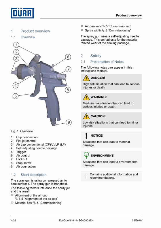
Fig. 1: Overview
1 Cup connection2 Flat jet control3 Air cap conventional (CF)/LVLP (LF)4 Self-adjusting needle package5 Trigger6 Air control7 Locknut8 Stop screw9 Air connection
1.2 Short descriptionThe spray gun is using compressed air tocoat surfaces. The spray gun is handheld.The following factors influence the spray jetand the result:
Alignment of the air capÄ 6.5 “Alignment of the air cap”Material flow Ä 5 “Commissioning”
Air pressure Ä 5 “Commissioning”Spray width Ä 5 “Commissioning”
The spray gun uses a self-adjusting needlepackage. This self-adjusts for the materialrelated wear of the sealing package.
2 Safety2.1 Presentation of NotesThe following notes can appear in thisinstructions manual.
DANGER!
High risk situation that can lead to seriousinjuries or death.
WARNING!
Medium risk situation that can lead toserious injuries or death.
CAUTION!
Low risk situations that can lead to minorinjuries.
NOTICE!
Situations that can lead to materialdamage.
ENVIRONMENT!
Situations that can lead to environmentaldamage.
Contains additional information andrecommendations.
Product overview
05/2018EcoGun 910 - MSG00003EN4/32
2.2 Intended UseThe spray gun EcoGun 910 is used exclu-sively for spraying water-based paint andconventional solvent-based paint. It is handguided and uses compressed air.The EcoGun 910 spray gun may only beoperated in the approved EX-zones andwithin the approved technical data Ä 10“Technical data”.The EcoGun 910 spray gun is only intendedfor use in application stations.
MisuseThere is a risk of death if not used properly.Misuses include, e. g.:
Aiming the spray gun at humans or ani-mals.Atomization of fluid nitrogenCombination of the spray gun with com-ponents that are not approved byDürr Systems for operation.Use of unapproved materials, see safetydata sheetsMaking conversions or changes on yourownUse of spray guns not conforming to thedevice category in Ex zones.
EX labeling
II 2G T60 °C X
II - Device group II: all areas exceptmining
2G - Device category 2 for gas
T60 °C - Surface temperature, max. 60 °C
X - Specific operating conditions forsafe operation
The following conditions must be observedfor safe operation:
Ground the spray gun.Only use conductive hoses.Ensure that static electricity can be dis-charged.
Use exclusively compressed air quickcouplings for water-based materials,where it is not necessary to keep dis-charging static electrical charges.
2.3 Residual risksExplosionSparks, open flames and hot surfaces cancause explosions in explosive atmospheres.Serious injuries and death can be the conse-quence.
Before carrying out any work, ensure anon-explosive atmosphere.Do not use sources of ignition and openlight.Do not smoke.Ground the product.Ground the work piece.Only use conductive lines.
Flammable coating materials and their deter-gents and cleaning agents can cause a fireor an explosion.
Ensure that the flashpoint of the fluid is atleast 15 K above the ambient tempera-ture.Note explosion group of the fluid.Follow safety data sheets.Ensure that forced ventilation and fireprotection equipment are in operation.Do not use any sources of ignition andopen light.Do not smoke.
Danger from harmful or irritant sub-stancesContact with hazardous liquids or vapors,can result in serious injury or death.
Ensure that the forced ventilation isoperational.Follow safety data sheets.Wear specified protective equipment.
Escaping materialMaterial escaping under pressure can causeserious injuries.
Safety
05/2018 EcoGun 910 - MSG00003EN 5/32
Before working on the product:Disconnect the system with the productfrom compressed air and material supply.Relieve the lines.Secure the system against reconnection.
NoiseThe noise during normal operation maycause severe hearing damage.
Wear hearing protection.Do not spend more time then necessaryin the work area.
Hot surfacesDuring normal operation the surfaces ofcomponents can get extremely hot. Contactwith it can cause burns.Before carrying out any work:
Check the temperature.Do not touch hot surfaces.Let components cool down.Wear protective gloves.
2.4 Staff qualification
WARNING!
Inadequate qualificationWrong estimation of dangers can causeserious injury or death.– Only sufficiently qualified persons may
execute all work.– Some work requires additional qualifi-
cation. Additional qualifications aremarked with a “+”.
This document is intended for qualified per-sonnel in the industry.OperatorThe operator is trained specifically for thefield of work in which he works.Furthermore, the operator possesses the fol-lowing knowledge:
Technical Measures for occupationalsafety and health
The operator is responsible for the followingwork:
Operate and monitor the system/ product.Introduce measures in the event of faults.Clean system/ product.
+ additional qualification explosion pro-tectionIn addition to the knowledge of the variousspecialist fields, the mechanic has knowl-edge of regulations and safety measureswhen working in potentially explosive areas.
Dürr Systems offers special product trainingfor Ä “Hotline and Contact”.
2.5 Personal protective equipmentWhen working in explosive areas, the pro-tective clothing, including gloves, must meetthe requirements of DIN EN 1149-5. Foot-wear must meet the requirements of EN ISO20344. The insulation resistor must notexceed 100 MΩ.
Wear the specified personal protectiveequipment when working. Provide the fol-lowing personal protective equipment:
3 Transport, scope of supplyand storage
3.1 Scope of deliveryThe scope of supply includes the followingcomponents:
Spray gunTool kit Ä 11.2 “Tools”
Inspect delivery on receipt for completenessand integrity.
Transport, scope of supply and storage
05/2018EcoGun 910 - MSG00003EN6/32
Report defects immediately Ä “Hotline andContact”.
3.2 Handling of packaging material
ENVIRONMENT!
Incorrect disposalIncorrectly disposed packaging materialcan damage environment.– Dispose of material no longer required
in an environment-friendly manner.– Observe local disposal specifications.
3.3 StorageRequirements for the warehouse:
Do not store outdoors.Store in a dry and dust-free place.Do not expose to aggressive media.Protect from solar radiation.Avoid mechanical vibrations.Temperature: 10°C to 40°CRelative humidity: 35% to 90%
4 Assembly4.1 Requirements for the
Installation point.It must be possible to disconnect thecompressed air supply to the spray gunand secure it against reconnection.The compressed air supply must beadjustable.Lines, seals and screw connections mustbe designed to conform to the spray gunrequirements Ä 10 “Technical data”.The workplace must have technical venti-lation.
Working environment and groundingFlooring of the working areas must be anti-static, according to DIN EN50050-1:2014-03, measurement accordingto DIN EN 1081:1998-04.
4.2 AssemblyPersonnel:
Operator + additional qualification explosion pro-tection
Protective equipment:Protective workwearProtective gloves
1. WARNING!
Sources of ignition may cause explo-sions!
Ensure a non-explosive atmosphere.
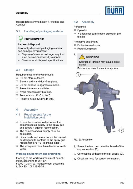
Fig. 2: Assembly
2. Screw the feed cup onto the thread of thecup connection (1).
3. Connect the air hose to the air supply (2).
4. Check air hose for correct connection.
Assembly
05/2018 EcoGun 910 - MSG00003EN 7/32
5 CommissioningPersonnel:
Operator + additional qualification explosion pro-tection
Protective equipment:Protective glovesSafety bootsProtective workwearEye protectionRespiratory protection deviceUse ear protection
Requirements:Feed cup and air hose have been con-nected Ä 4.2 “Assembly”.
Fig. 3: Commissioning
1. Rinse the spray gun before filling it withpaint Ä 6.7 “Rinsing”:
use solvent for solvent-based paintsuse water for water-based paints
2. Set air control lever (1) into vertical posi-tion.
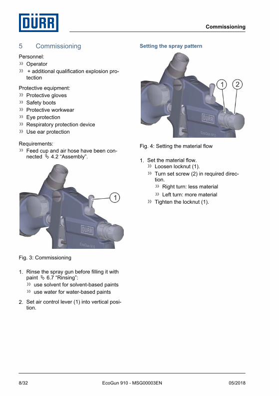
Setting the spray pattern
Fig. 4: Setting the material flow
1. Set the material flow.Loosen locknut (1).Turn set screw (2) in required direc-tion.
Right turn: less materialLeft turn: more material
Tighten the locknut (1).
Commissioning
05/2018EcoGun 910 - MSG00003EN8/32
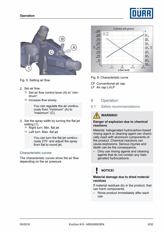
Fig. 5: Setting air flow
2. Set air flow.Set air flow control lever (A) to “min-imum”.Increase flow slowly.
You can regulate the air continu-ously from “minimum” (A) to“maximum” (C).
3. Set the spray width by turning the flat jetsetting (1).
Right turn: Min. flat jetLeft turn: Max. flat jet
You can turn the flat jet continu-ously 270° and adjust the sprayfrom flat to round jet.
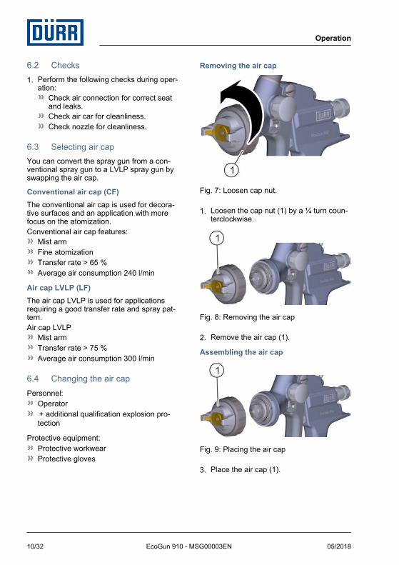
Characteristic curvesThe characteristic curves show the air flowdepending on the air pressure
Fig. 6: Characteristic curve
CF Conventional air capLF Air cap LVLP
6 Operation6.1 Safety recommendations
WARNING!
Danger of explosion due to chemicalreactionsMaterial, halogenated hydrocarbon-basedrinsing agent or cleaning agent can chemi-cally react with aluminum components ofthe product. Chemical reactions cancause explosions. Serious injuries anddeath can be the consequence.– Only use rinsing agents and cleaning
agents that do not contain any halo-genated hydrocarbons.
NOTICE!
Material damage due to dried materialresiduesIf material residues dry in the product, thatcan harm components.– Rinse product immediately after each
use.
Operation
05/2018 EcoGun 910 - MSG00003EN 9/32
6.2 Checks1. Perform the following checks during oper-
ation:Check air connection for correct seatand leaks.Check air car for cleanliness.Check nozzle for cleanliness.
6.3 Selecting air capYou can convert the spray gun from a con-ventional spray gun to a LVLP spray gun byswapping the air cap.
Conventional air cap (CF)The conventional air cap is used for decora-tive surfaces and an application with morefocus on the atomization.Conventional air cap features:
Mist armFine atomizationTransfer rate > 65 %Average air consumption 240 l/min
Air cap LVLP (LF)The air cap LVLP is used for applicationsrequiring a good transfer rate and spray pat-tern.Air cap LVLP
Mist armTransfer rate > 75 %Average air consumption 300 l/min
6.4 Changing the air capPersonnel:
Operator + additional qualification explosion pro-tection
Protective equipment:Protective workwearProtective gloves
Removing the air cap
Fig. 7: Loosen cap nut.
1. Loosen the cap nut (1) by a ¼ turn coun-terclockwise.
Fig. 8: Removing the air cap
2. Remove the air cap (1).
Assembling the air cap
Fig. 9: Placing the air cap
3. Place the air cap (1).
Operation
05/2018EcoGun 910 - MSG00003EN10/32
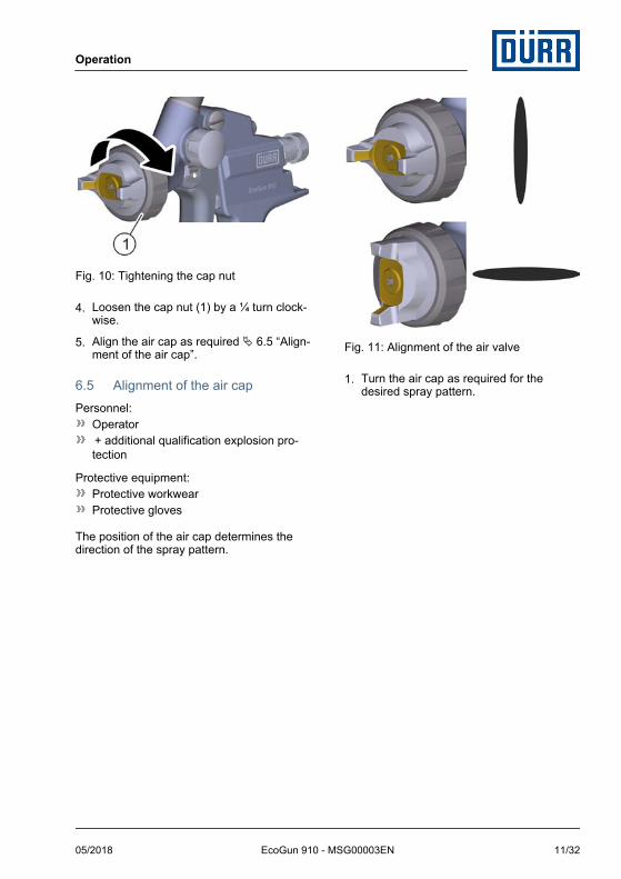
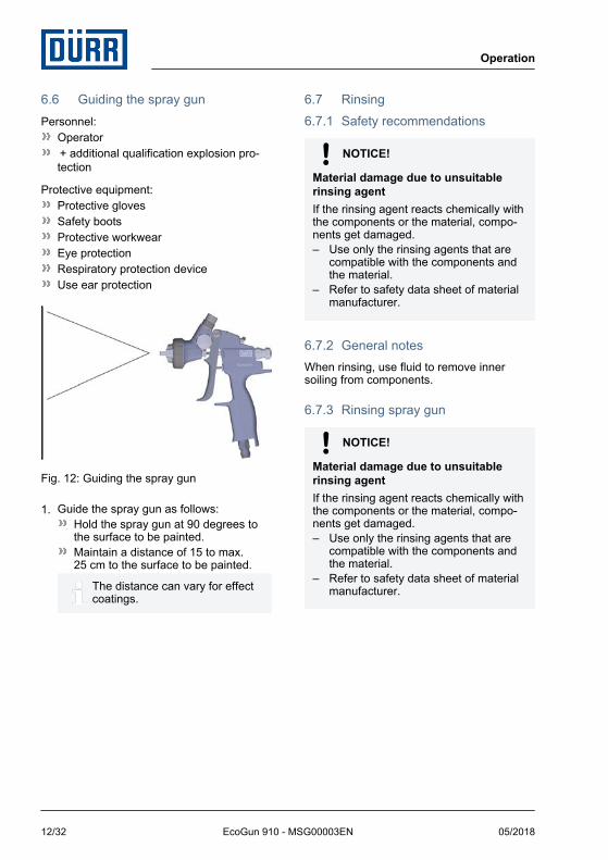
Fig. 10: Tightening the cap nut
4. Loosen the cap nut (1) by a ¼ turn clock-wise.
5. Align the air cap as required Ä 6.5 “Align-ment of the air cap”.
6.5 Alignment of the air capPersonnel:
Operator + additional qualification explosion pro-tection
Protective equipment:Protective workwearProtective gloves
The position of the air cap determines thedirection of the spray pattern.
Fig. 11: Alignment of the air valve
1. Turn the air cap as required for thedesired spray pattern.
Operation
05/2018 EcoGun 910 - MSG00003EN 11/32
6.6 Guiding the spray gunPersonnel:
Operator + additional qualification explosion pro-tection
Protective equipment:Protective glovesSafety bootsProtective workwearEye protectionRespiratory protection deviceUse ear protection
Fig. 12: Guiding the spray gun
1. Guide the spray gun as follows:Hold the spray gun at 90 degrees tothe surface to be painted.Maintain a distance of 15 to max.25 cm to the surface to be painted.
The distance can vary for effectcoatings.
6.7 Rinsing6.7.1 Safety recommendations
NOTICE!
Material damage due to unsuitablerinsing agentIf the rinsing agent reacts chemically withthe components or the material, compo-nents get damaged.– Use only the rinsing agents that are
compatible with the components andthe material.
– Refer to safety data sheet of materialmanufacturer.
6.7.2 General notesWhen rinsing, use fluid to remove innersoiling from components.
6.7.3 Rinsing spray gun
NOTICE!
Material damage due to unsuitablerinsing agentIf the rinsing agent reacts chemically withthe components or the material, compo-nents get damaged.– Use only the rinsing agents that are
compatible with the components andthe material.
– Refer to safety data sheet of materialmanufacturer.
Operation
05/2018EcoGun 910 - MSG00003EN12/32
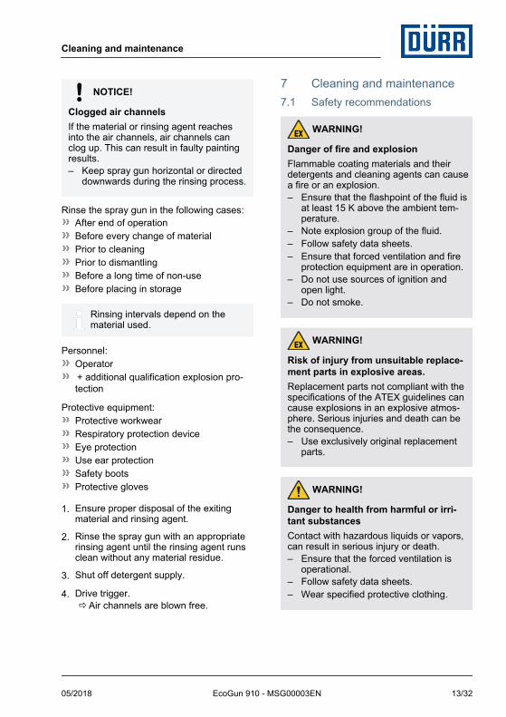
NOTICE!
Clogged air channelsIf the material or rinsing agent reachesinto the air channels, air channels canclog up. This can result in faulty paintingresults.– Keep spray gun horizontal or directed
downwards during the rinsing process.
Rinse the spray gun in the following cases:After end of operationBefore every change of materialPrior to cleaningPrior to dismantlingBefore a long time of non-useBefore placing in storage
Rinsing intervals depend on thematerial used.
Personnel:Operator + additional qualification explosion pro-tection
Protective equipment:Protective workwearRespiratory protection deviceEye protectionUse ear protectionSafety bootsProtective gloves
1. Ensure proper disposal of the exitingmaterial and rinsing agent.
2. Rinse the spray gun with an appropriaterinsing agent until the rinsing agent runsclean without any material residue.
3. Shut off detergent supply.
4. Drive trigger.ðAir channels are blown free.
7 Cleaning and maintenance7.1 Safety recommendations
WARNING!
Danger of fire and explosionFlammable coating materials and theirdetergents and cleaning agents can causea fire or an explosion.– Ensure that the flashpoint of the fluid is
at least 15 K above the ambient tem-perature.
– Note explosion group of the fluid.– Follow safety data sheets.– Ensure that forced ventilation and fire
protection equipment are in operation.– Do not use sources of ignition and
open light.– Do not smoke.
WARNING!
Risk of injury from unsuitable replace-ment parts in explosive areas.Replacement parts not compliant with thespecifications of the ATEX guidelines cancause explosions in an explosive atmos-phere. Serious injuries and death can bethe consequence.– Use exclusively original replacement
parts.
WARNING!
Danger to health from harmful or irri-tant substancesContact with hazardous liquids or vapors,can result in serious injury or death.– Ensure that the forced ventilation is
operational.– Follow safety data sheets.– Wear specified protective clothing.
Cleaning and maintenance
05/2018 EcoGun 910 - MSG00003EN 13/32
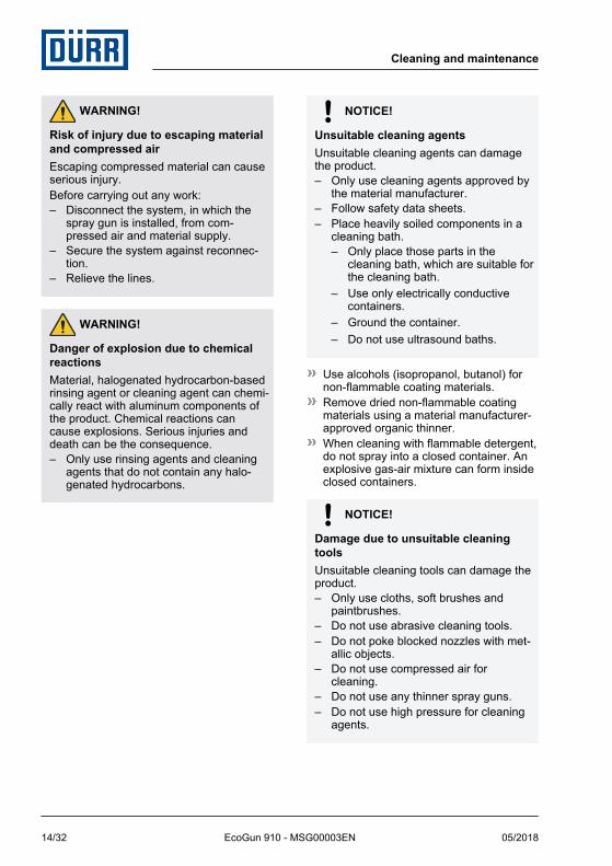
WARNING!
Risk of injury due to escaping materialand compressed airEscaping compressed material can causeserious injury.Before carrying out any work:– Disconnect the system, in which the
spray gun is installed, from com-pressed air and material supply.
– Secure the system against reconnec-tion.
– Relieve the lines.
WARNING!
Danger of explosion due to chemicalreactionsMaterial, halogenated hydrocarbon-basedrinsing agent or cleaning agent can chemi-cally react with aluminum components ofthe product. Chemical reactions cancause explosions. Serious injuries anddeath can be the consequence.– Only use rinsing agents and cleaning
agents that do not contain any halo-genated hydrocarbons.
NOTICE!
Unsuitable cleaning agentsUnsuitable cleaning agents can damagethe product.– Only use cleaning agents approved by
the material manufacturer.– Follow safety data sheets.– Place heavily soiled components in a
cleaning bath.– Only place those parts in the
cleaning bath, which are suitable forthe cleaning bath.
– Use only electrically conductivecontainers.
– Ground the container.– Do not use ultrasound baths.
Use alcohols (isopropanol, butanol) fornon-flammable coating materials.Remove dried non-flammable coatingmaterials using a material manufacturer-approved organic thinner.When cleaning with flammable detergent,do not spray into a closed container. Anexplosive gas-air mixture can form insideclosed containers.
NOTICE!
Damage due to unsuitable cleaningtoolsUnsuitable cleaning tools can damage theproduct.– Only use cloths, soft brushes and
paintbrushes.– Do not use abrasive cleaning tools.– Do not poke blocked nozzles with met-
allic objects.– Do not use compressed air for
cleaning.– Do not use any thinner spray guns.– Do not use high pressure for cleaning
agents.
Cleaning and maintenance
05/2018EcoGun 910 - MSG00003EN14/32
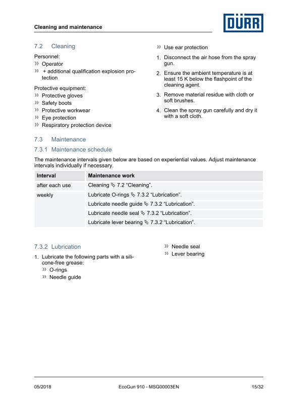
7.2 CleaningPersonnel:
Operator + additional qualification explosion pro-tection
Protective equipment:Protective glovesSafety bootsProtective workwearEye protectionRespiratory protection device
Use ear protection
1. Disconnect the air hose from the spraygun.
2. Ensure the ambient temperature is atleast 15 K below the flashpoint of thecleaning agent.
3. Remove material residue with cloth orsoft brushes.
4. Clean the spray gun carefully and dry itwith a soft cloth.
7.3 Maintenance7.3.1 Maintenance scheduleThe maintenance intervals given below are based on experiential values. Adjust maintenanceintervals individually if necessary.
Interval Maintenance work
after each use Cleaning Ä 7.2 “Cleaning”.
weekly Lubricate O-rings Ä 7.3.2 “Lubrication”.Lubricate needle guide Ä 7.3.2 “Lubrication”.Lubricate needle seal Ä 7.3.2 “Lubrication”.Lubricate lever bearing Ä 7.3.2 “Lubrication”.
7.3.2 Lubrication1. Lubricate the following parts with a sili-
cone-free grease:O-ringsNeedle guide
Needle sealLever bearing
Cleaning and maintenance
05/2018 EcoGun 910 - MSG00003EN 15/32
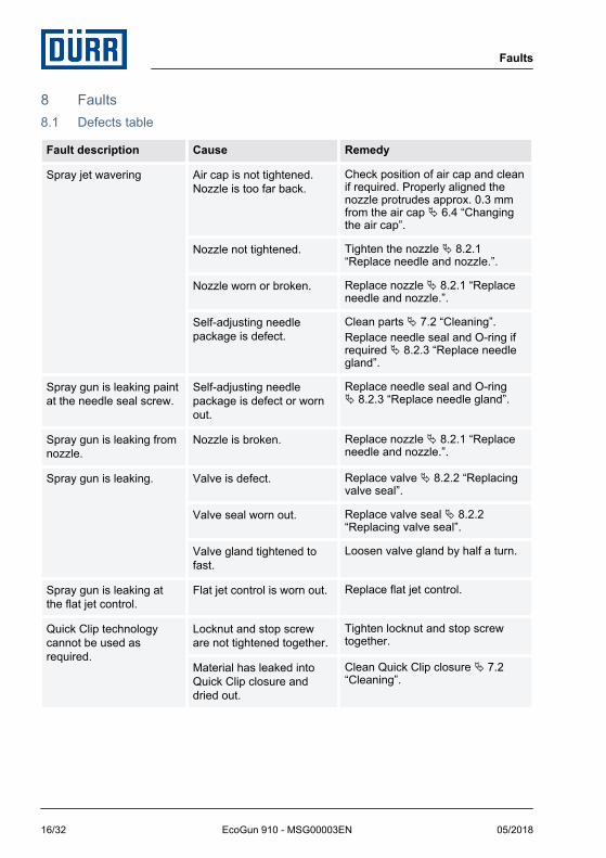
8 Faults8.1 Defects table
Fault description Cause Remedy
Spray jet wavering Air cap is not tightened.Nozzle is too far back.
Check position of air cap and cleanif required. Properly aligned thenozzle protrudes approx. 0.3 mmfrom the air cap Ä 6.4 “Changingthe air cap”.
Nozzle not tightened. Tighten the nozzle Ä 8.2.1“Replace needle and nozzle.”.
Nozzle worn or broken. Replace nozzle Ä 8.2.1 “Replaceneedle and nozzle.”.
Self-adjusting needlepackage is defect.
Clean parts Ä 7.2 “Cleaning”.Replace needle seal and O-ring ifrequired Ä 8.2.3 “Replace needlegland”.
Spray gun is leaking paintat the needle seal screw.
Self-adjusting needlepackage is defect or wornout.
Replace needle seal and O-ringÄ 8.2.3 “Replace needle gland”.
Spray gun is leaking fromnozzle.
Nozzle is broken. Replace nozzle Ä 8.2.1 “Replaceneedle and nozzle.”.
Spray gun is leaking. Valve is defect. Replace valve Ä 8.2.2 “Replacingvalve seal”.
Valve seal worn out. Replace valve seal Ä 8.2.2“Replacing valve seal”.
Valve gland tightened tofast.
Loosen valve gland by half a turn.
Spray gun is leaking atthe flat jet control.
Flat jet control is worn out. Replace flat jet control.
Quick Clip technologycannot be used asrequired.
Locknut and stop screware not tightened together.
Tighten locknut and stop screwtogether.
Material has leaked intoQuick Clip closure anddried out.
Clean Quick Clip closure Ä 7.2“Cleaning”.
Faults
05/2018EcoGun 910 - MSG00003EN16/32
8.2 Troubleshooting8.2.1 Replace needle and nozzle.
NOTICE!
Property damage due to improperreplacement of needle and nozzleReplacing only the needle or only thenozzle could damage spray gun compo-nents. This can compromise the tightnessof the spray gun. The spray pattern deteri-orates.– Observe order of replacement steps
(needle – nozzle).– Observe order of assembly steps
(nozzle – needle).– Always replace nozzle and needle at
the same time.
The integrated Quick Clip technology allowsfor removal and installation of the needlewithout changing the preset needle stop.Personnel:
Operator + additional qualification explosion pro-tection
Protective equipment:Protective glovesSafety bootsProtective workwearEye protectionRespiratory protection deviceUse ear protection
Removing the needle
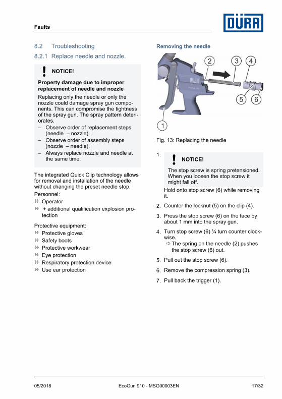
Fig. 13: Replacing the needle
1. NOTICE!
The stop screw is spring pretensioned.When you loosen the stop screw itmight fall off.
Hold onto stop screw (6) while removingit.
2. Counter the locknut (5) on the clip (4).
3. Press the stop screw (6) on the face byabout 1 mm into the spray gun.
4. Turn stop screw (6) ¼ turn counter clock-wise.ðThe spring on the needle (2) pushes
the stop screw (6) out.
5. Pull out the stop screw (6).
6. Remove the compression spring (3).
7. Pull back the trigger (1).
Faults
05/2018 EcoGun 910 - MSG00003EN 17/32
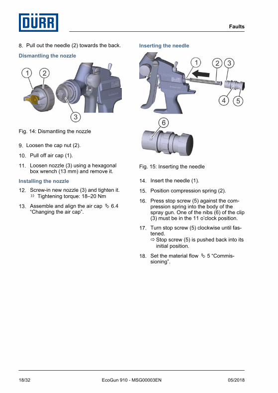
8. Pull out the needle (2) towards the back.
Dismantling the nozzle
Fig. 14: Dismantling the nozzle
9. Loosen the cap nut (2).
10. Pull off air cap (1).
11. Loosen nozzle (3) using a hexagonalbox wrench (13 mm) and remove it.
Installing the nozzle12. Screw-in new nozzle (3) and tighten it.
Tightening torque: 18–20 Nm
13. Assemble and align the air cap Ä 6.4“Changing the air cap”.
Inserting the needle
Fig. 15: Inserting the needle
14. Insert the needle (1).
15. Position compression spring (2).
16. Press stop screw (5) against the com-pression spring into the body of thespray gun. One of the nibs (6) of the clip(3) must be in the 11 o’clock position.
17. Turn stop screw (5) clockwise until fas-tened.ðStop screw (5) is pushed back into its
initial position.
18. Set the material flow Ä 5 “Commis-sioning”.
Faults
05/2018EcoGun 910 - MSG00003EN18/32
8.2.2 Replacing valve sealPersonnel:
Operator + additional qualification explosion pro-tection
Protective equipment:Protective workwearProtective gloves
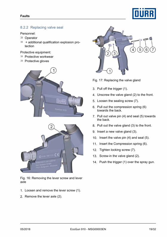
Fig. 16: Removing the lever screw and leveraxle
1. Loosen and remove the lever screw (1).
2. Remove the lever axle (2).
Fig. 17: Replacing the valve gland
3. Pull off the trigger (1).
4. Unscrew the valve gland (2) to the front.
5. Loosen the sealing screw (7).
6. Pull out the compression spring (6)towards the back.
7. Pull out valve pin (4) and seal (5) towardsthe back.
8. Pull out the valve gland (3) to the front.
9. Insert a new valve gland (3).
10. Insert the valve pin (4) and seal (5).
11. Insert the Compression spring (6).
12. Tighten locking screw (7).
13. Screw-in the valve gland (2).
14. Push the trigger (1) over the spray gun.
Faults
05/2018 EcoGun 910 - MSG00003EN 19/32
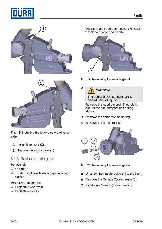
Fig. 18: Installing the lever screw and leveraxle
15. Insert lever axle (2).
16. Tighten the lever screw (1).
8.2.3 Replace needle glandPersonnel:
Operator + additional qualification explosion pro-tection
Protective equipment:Protective workwearProtective gloves
1. Disassemble needle and nozzle Ä 8.2.1“Replace needle and nozzle.”.
Fig. 19: Removing the needle gland
2. CAUTION!
The compression spring is pre-ten-sioned. Risk of injury!
Remove the needle gland (1) carefullyand relieve the compression springslowly.
3. Remove the compression spring.
4. Remove the pressure disc.
Fig. 20: Removing the needle guide
5. Unscrew the needle guide (1) to the front.
6. Remove the O-rings (2) and seals (3).
7. Install new O-rings (2) and seals (3).
Faults
05/2018EcoGun 910 - MSG00003EN20/32
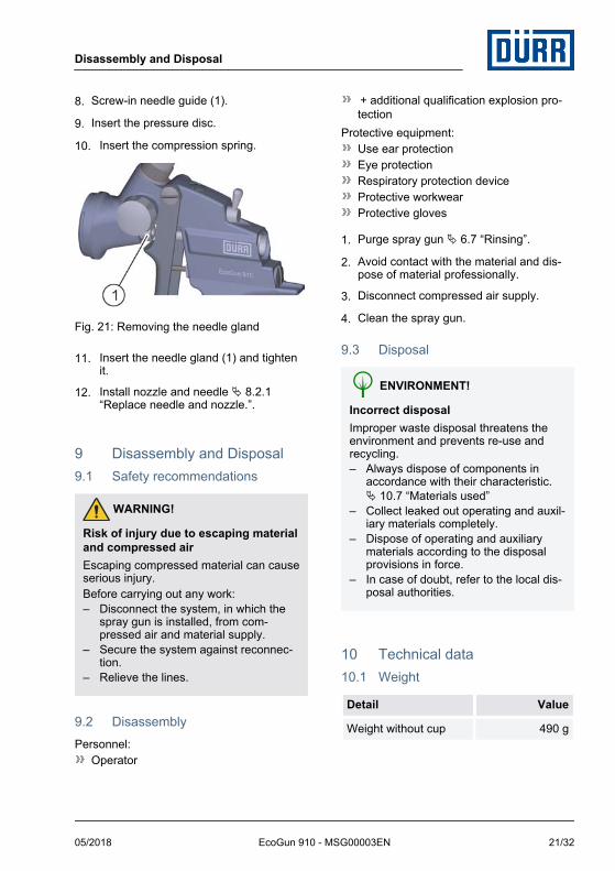
8. Screw-in needle guide (1).
9. Insert the pressure disc.
10. Insert the compression spring.
Fig. 21: Removing the needle gland
11. Insert the needle gland (1) and tightenit.
12. Install nozzle and needle Ä 8.2.1“Replace needle and nozzle.”.
9 Disassembly and Disposal9.1 Safety recommendations
WARNING!
Risk of injury due to escaping materialand compressed airEscaping compressed material can causeserious injury.Before carrying out any work:– Disconnect the system, in which the
spray gun is installed, from com-pressed air and material supply.
– Secure the system against reconnec-tion.
– Relieve the lines.
9.2 DisassemblyPersonnel:
Operator
+ additional qualification explosion pro-tection
Protective equipment:Use ear protectionEye protectionRespiratory protection deviceProtective workwearProtective gloves
1. Purge spray gun Ä 6.7 “Rinsing”.
2. Avoid contact with the material and dis-pose of material professionally.
3. Disconnect compressed air supply.
4. Clean the spray gun.
9.3 Disposal
ENVIRONMENT!
Incorrect disposalImproper waste disposal threatens theenvironment and prevents re-use andrecycling.– Always dispose of components in
accordance with their characteristic.Ä 10.7 “Materials used”
– Collect leaked out operating and auxil-iary materials completely.
– Dispose of operating and auxiliarymaterials according to the disposalprovisions in force.
– In case of doubt, refer to the local dis-posal authorities.
10 Technical data10.1 Weight
Detail Value
Weight without cup 490 g
Disassembly and Disposal
05/2018 EcoGun 910 - MSG00003EN 21/32
10.2 ConnectionsÄ 11.1 “Spare part”
10.3 Operating conditions
Detail Value
Maximum allowable mate-rial temperature whenoperating with protectivegloves
40 °C
Maximum allowable mate-rial temperature whenoperating with heat-resistant protective gloves
60 °C
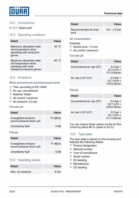
10.4 EmissionsWork environment sound pressure level
Test: according to EN 14462Air cap: conventionalMaterial: WaterAir control: maximumAir pressure: 2.5 bar
Circular jet
Detail Value
A-weighted emissionsound pressure level LpA
74 dB(A)
Uncertainty KpA 5 dB
Flat jet
Detail Value
A-weighted emissionsound pressure level LpA
77 dB(A)
Uncertainty KpA 5 dB
10.5 Operating values
Detail Value
Max. air pressure 8 bar
Detail Value
Recommended air pres-sure
2.0 – 3.0 bar
Air consumptionExample:
Nozzle bore: 1.4 mmAir control: maximum
Circular jet
Detail Value
Conventional air cap (CF) 2.5 bar =10.3 m³/h =
171.0 Nl/min
Air cap LVLP (LF) 2.5 bar =10.7 m³/h =
178.0 Nl/min
Flat jet
Detail Value
Conventional air cap (CF) 2.5 bar =16.7 m³/h =
278.0 Nl/min
Air cap LVLP (LF) 2.5 bar =18.7 m³/h =
311.0 Nl/min
You can reduce these values via the air flowcontrol by about 80 % (down to 20 %).
10.6 Type plateThe type plate is placed on the housing andfeatures the following details:
Product designationMaterial numberYear of manufactureSerial numberEX labelingManufacturerCE labeling
Technical data
05/2018EcoGun 910 - MSG00003EN22/32
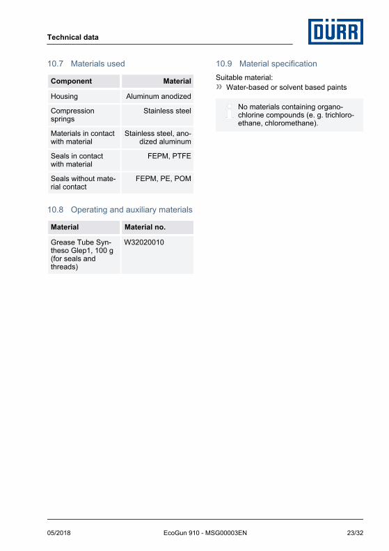
10.7 Materials used
Component Material
Housing Aluminum anodized
Compressionsprings
Stainless steel
Materials in contactwith material
Stainless steel, ano-dized aluminum
Seals in contactwith material
FEPM, PTFE
Seals without mate-rial contact
FEPM, PE, POM
10.8 Operating and auxiliary materials
Material Material no.
Grease Tube Syn-theso Glep1, 100 g(for seals andthreads)
W32020010
10.9 Material specificationSuitable material:
Water-based or solvent based paints
No materials containing organo-chlorine compounds (e. g. trichloro-ethane, chloromethane).
Technical data
05/2018 EcoGun 910 - MSG00003EN 23/32
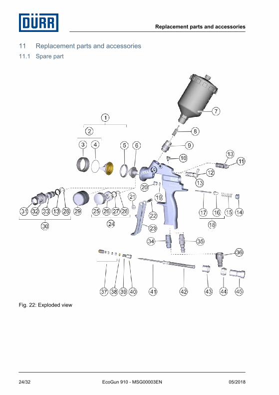
11 Replacement parts and accessories11.1 Spare part
Fig. 22: Exploded view
Replacement parts and accessories
05/2018EcoGun 910 - MSG00003EN24/32
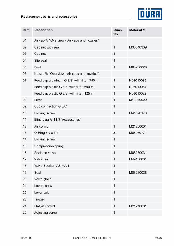
Item Description Quan-tity
Material #
01 Air cap Ä “Overview - Air caps and nozzles”
02 Cap nut with seal 1 M30010309
03 Cap nut 1
04 Slip seal 1
05 Seal 1 M08280029
06 Nozzle Ä “Overview - Air caps and nozzles”
07 Feed cup aluminum G 3/8" with filter, 750 ml 1 N08010035
Feed cup plastic G 3/8" with filter, 600 ml 1 N08010034
Feed cup plastic G 3/8" with filter, 125 ml 1 N08010032
08 Filter 1 M13010029
09 Cup connection G 3/8" 1
10 Locking screw 1 M41090173
11 Blind plug Ä 11.3 “Accessories”
12 Air control 1 M21200001
13 O-Ring 7.0 x 1.5 3 M08030771
14 Locking screw 1
15 Compression spring 1
16 Seals on valve 1 M08280031
17 Valve pin 1 M49150001
18 Valve EcoGun AS MAN 1
19 Seal 1 M08280028
20 Valve gland 1
21 Lever screw 1
22 Lever axle 1
23 Trigger 1
24 Flat jet control 1 M21210001
25 Adjusting screw 1
Replacement parts and accessories
05/2018 EcoGun 910 - MSG00003EN 25/32
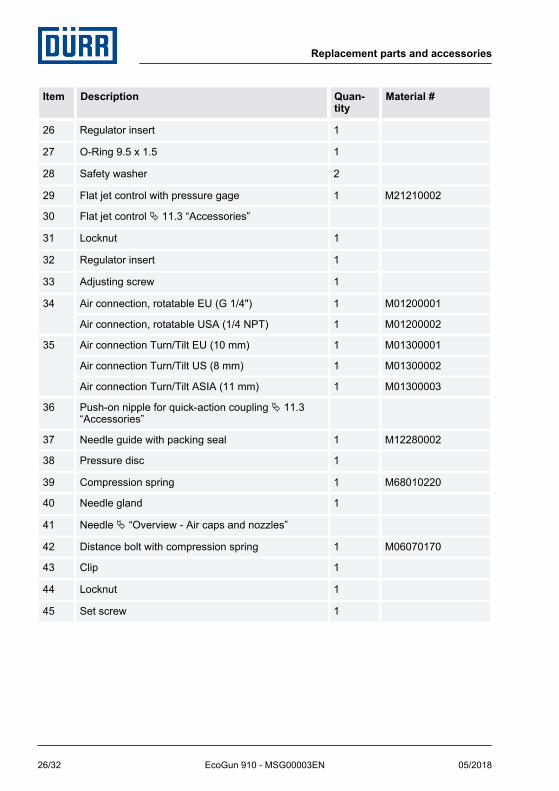
Item Description Quan-tity
Material #
26 Regulator insert 1
27 O-Ring 9.5 x 1.5 1
28 Safety washer 2
29 Flat jet control with pressure gage 1 M21210002
30 Flat jet control Ä 11.3 “Accessories”
31 Locknut 1
32 Regulator insert 1
33 Adjusting screw 1
34 Air connection, rotatable EU (G 1/4") 1 M01200001
Air connection, rotatable USA (1/4 NPT) 1 M01200002
35 Air connection Turn/Tilt EU (10 mm) 1 M01300001
Air connection Turn/Tilt US (8 mm) 1 M01300002
Air connection Turn/Tilt ASIA (11 mm) 1 M01300003
36 Push-on nipple for quick-action coupling Ä 11.3“Accessories”
37 Needle guide with packing seal 1 M12280002
38 Pressure disc 1
39 Compression spring 1 M68010220
40 Needle gland 1
41 Needle Ä “Overview - Air caps and nozzles”
42 Distance bolt with compression spring 1 M06070170
43 Clip 1
44 Locknut 1
45 Set screw 1
Replacement parts and accessories
05/2018EcoGun 910 - MSG00003EN26/32
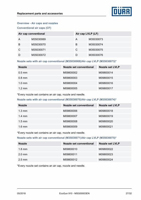
Overview - Air caps and nozzlesConventional air caps (CF)
Air cap conventional Air cap LVLP (LF)
A M35030069 A M35030073
B M35030070 B M35030074
C M35030071 C M35030075
D M35030072 D M35030076
Nozzle sets with air cap conventional (M35030069)/Air cap LVLP (M35030073)*
Nozzle Nozzle set conventional Nozzle set LVLP
0.5 mm M09800002 M09800014
0.8 mm M09800003 M09800015
1.0 mm M09800004 M09800016
1.2 mm M09800005 M09800017
*Every nozzle set contains an air cap, nozzle and needle.
Nozzle sets with air cap conventional (M35030070)/Air cap LVLP (M35030074)*
Nozzle Nozzle set conventional Nozzle set LVLP
1.3 mm M09800006 M09800018
1.4 mm M09800007 M09800019
1.5 mm M09800008 M09800020
1.6 mm M09800009 M09800021
*Every nozzle set contains an air cap, nozzle and needle.
Nozzle sets with air cap conventional (M35030071)/Air cap LVLP (M35030075)*
Nozzle Nozzle set conventional Nozzle set LVLP
1.8 mm M09800010 M09800022
2.0 mm M09800011 M09800023
2.5 mm M09800012 M09800024
*Every nozzle set contains an air cap, nozzle and needle.
Replacement parts and accessories
05/2018 EcoGun 910 - MSG00003EN 27/32
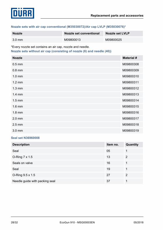
Nozzle sets with air cap conventional (M35030072)/Air cap LVLP (M35030076)*
Nozzle Nozzle set conventional Nozzle set LVLP
3.0 mm M09800013 M09800025
*Every nozzle set contains an air cap, nozzle and needle.Nozzle sets without air cap (consisting of nozzle (6) and needle (40))
Nozzle Material #
0.5 mm M09800308
0.8 mm M09800309
1.0 mm M09800310
1.2 mm M09800311
1.3 mm M09800312
1.4 mm M09800313
1.5 mm M09800314
1.6 mm M09800315
1.8 mm M09800316
2.0 mm M09800317
2.5 mm M09800318
3.0 mm M09800319
Seal set N36960008
Description Item no. Quantity
Seal 05 1
O-Ring 7 x 1.5 13 2
Seals on valve 16 1
Seal 19 1
O-Ring 9.5 x 1.5 27 2
Needle guide with packing seal 37 1
Replacement parts and accessories
05/2018EcoGun 910 - MSG00003EN28/32
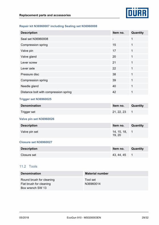
Repair kit N36960007 including Sealing set N36960008
Description Item no. Quantity
Seal set N36960008 - 1
Compression spring 15 1
Valve pin 17 1
Valve gland 20 1
Lever screw 21 1
Lever axle 22 1
Pressure disc 38 1
Compression spring 39 1
Needle gland 40 1
Distance bolt with compression spring 42 1
Trigger set N36960025
Denomination Item no. Quantity
Trigger set 21, 22, 23 1
Valve pin set N36960026
Description Item no. Quantity
Valve pin set 14, 15, 18,19, 20
1
Closure set N36960027
Description Item no. Quantity
Closure set 43, 44, 45 1
11.2 Tools
Denomination Material number
Round brush for cleaningFlat brush for cleaningBox wrench SW 13
Tool setN36960014
Replacement parts and accessories
05/2018 EcoGun 910 - MSG00003EN 29/32
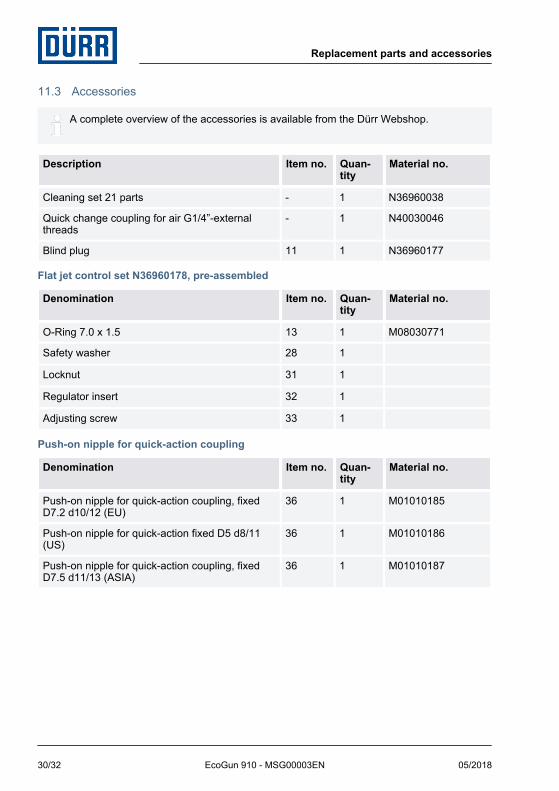
11.3 Accessories
A complete overview of the accessories is available from the Dürr Webshop.
Description Item no. Quan-tity
Material no.
Cleaning set 21 parts - 1 N36960038
Quick change coupling for air G1/4”-externalthreads
- 1 N40030046
Blind plug 11 1 N36960177
Flat jet control set N36960178, pre-assembled
Denomination Item no. Quan-tity
Material no.
O-Ring 7.0 x 1.5 13 1 M08030771
Safety washer 28 1
Locknut 31 1
Regulator insert 32 1
Adjusting screw 33 1
Push-on nipple for quick-action coupling
Denomination Item no. Quan-tity
Material no.
Push-on nipple for quick-action coupling, fixedD7.2 d10/12 (EU)
36 1 M01010185
Push-on nipple for quick-action fixed D5 d8/11(US)
36 1 M01010186
Push-on nipple for quick-action coupling, fixedD7.5 d11/13 (ASIA)
36 1 M01010187
Replacement parts and accessories
05/2018EcoGun 910 - MSG00003EN30/32
11.4 Order
WARNING!
Risk of injury from unsuitable replace-ment parts in explosive areas.Replacement parts not compliant with thespecifications of the ATEX guidelines cancause explosions in an explosive atmos-phere. Serious injuries and death can bethe consequence.– Use exclusively original replacement
parts.
Ordering replacement parts, tools andaccessories as well as information on prod-ucts that are listed without order number.Ä “Hotline and Contact”
Replacement parts and accessories
05/2018 EcoGun 910 - MSG00003EN 31/32

Translation of the original operation manual
Dürr Systems AGApplication Technology
Carl-Benz-Str. 34D-74321 Bietigheim-Bissingen
Germanywww.durr.com
Phone +49 7142 78-0
Transmission and duplication of this document, as well as use and sharing of its contents are notpermitted without express written approval. Violations will be liable for compensation for damages.
All rights in the event of a patent grant or design registration are reserved.
© Dürr Systems AG 2015
www.durr.com