Embed Size (px)
Citation preview

Eco Sensors Ozone Controller Model OS-6 1
KWJ Engineering Instructions for Use, Rev. 1.2
Eco Sensors
OZONE CONTROLLER
Model OS-6
Instructions for Use
OS-6 Features
The OS-6 is an industrial grade ozone controller and monitor. The OS-6 design has been optimized for accuracy, ease of installation, setup and operation.
Easily accessible connection terminals and controls allow the unit to be setup after it is mounted.
Rugged, splash resistant enclosure and connectors for industrial environments.
Front panel digital LCD displays ozone level.
Indicators display when ozone exceeds the 0.1ppm OSHA limit and a variety of other important ozone control parameters.
Set points for ozone control relays are digitally controlled with numeric set points. This makes precise ozone control easy to set up, even if ozone is not present.
“Monitor Mode” can be enabled at the OS-6 panel. This mode disables the ozone generator controller and failure mode status indicators while maintaining ozone measurement and limit warning indicators.
User selectable PPM ranges for analog output (4-20 mA and 0-2 VDC)
Ozone generator failure detection option warns when the connected ozone generator is not maintaining the desired ozone set points. This option is disabled when the instrument is in Monitor Mode.

Eco Sensors Ozone Controller Model OS-6 2
KWJ Engineering Instructions for Use, Rev. 1.2
Indicator Lights and Display
PPM Ozone: Auto ranging digital display in PPM (Parts per Million)
Above MAX Limit: Illuminates when ozone reading is above the upper set point
Data From Sensor: Blinks at 1-second intervals when receiving data from sensor.
Below MIN Limit: Illuminates when ozone reading is below the lower set point.
Unable to Control Ozone: Illuminates when the ozone generator (TB4) is not maintaining the desired set points. A relay (TB6) engages with this indicator to provide remote alarm capability. This option is disabled when the instrument is in Monitor Mode. Refer to “Set Point and Alarm Condition Settings” for more details.
Above 0.1 PPM Safety Limit: Illuminates when the measured ozone exceeds 0.1 PPM (OSHA 8hr time-weighted average safety limit). A relay (TB5) engages with this indicator to provide remote alarm capability.
Generator Control: Illuminates when the ozone generator relay is engaged, indicating the ozone generator is on.

Eco Sensors Ozone Controller Model OS-6 3
KWJ Engineering Instructions for Use, Rev. 1.2
External Connections
Depiction of OS-6 Connection Board:
Terminal Block Descriptions:
TB1: 12-24 VDC POWER: Power input and earth grounding for the OS-6
TB2: ANALOG OUTPUT: 4-20mA and 0-2 VDC to external control equipment. Refer to “Analog Range Selection” for details. Default range is 0-20 PPM. NOTE: the 4-20 mA output is a DRIVER rather than a current-sink type output.
TB3: RS-232 OUT: Serial data output. Refer to “Data Connection” for details.
TB4: GENERATOR CONTROL: Relay with user adjustable control limits for operating an ozone generator. Refer to “Set Point and Alarm Condition Settings” for details.
TB5: ABOVE 0.1 PPM: Relay tied to OSHA human safety limit (for remote indicator/alarm).
TB6: UNABLE TO CONTROL OZONE: Relay tied to Unable to Control Ozone error condition (for remote indicator/alarm).
TB7: GENERATOR ENABLE: A jumper is installed at the factory to enable Generator Control (TB4). If the jumper is removed and these terminals are not connected, an ozone generator connected to TB4 will never run. Remove the jumper or replace it with a switch to disable the ozone generator when performing maintenance. Also remove the jumper to operate the OS-6 in “Monitor Mode”. In this state, when the jumper is removed, the Generator Control relay (TB4) will be disabled, as well as the “Generator Control” indicator and the “Unable to Control Ozone” indicator.
TB8: Sensor Data and Ground: Run cable from SM-4 TB1 BLK (grd) and WHT (data) to TB8.
Use either
Eco Sensors Ozone Controller Model OS-6 4
KWJ Engineering Instructions for Use, Rev. 1.2
TB9: SENSOR POWER: Power to sensor. Connect red wire either from:
+5V out to SM-4 TB1 +5V
OR
+12-24V out to SM-4 TB2 12-24V+
WARNING: Do not connect ‘+12-24 Out’ terminal on the OS-6 to the SM-4 TB1 ‘+5V’. This will damage the SM-4! The +12-24 terminal is in place to power the SM-4 over long cable lengths. Normally, the SM-4 will be shipped with a 6’ 3-wire cable connected to TB1 +5V, BLK (grd) and WHT (data).
AC Adapter
For 120 V, 60 HZ areas, the Eco Sensors P-20 adapter should be used. For all other areas, adapters should be purchased locally that fit local wall sockets and conform to local codes. The output should be 12 volts DC unregulated, 300-500 mA. The plug to our instrument should fit a 5.5/2.5 mm socket with the center pin +. For further details see our Tech Note P-101.
Initial Operation
All connections between the OS-6 and the SM-4 sensor unit are made at the factory. Connect the included P20 power adaptor (US, Canada and Mexico only) or your 12-24 VDC supply to terminals + and - of the terminal block, TB1. The green LED power/data indicator will illuminate and then blink at 1-second intervals. The LCD will power on and display digits. This indicates that the OS-6 is receiving sample data from the SM-4 sensing module.
Warm-up
In order to burn off any chemicals that the sensor may have absorbed during shipping and storage, you should let the OS-6 run with the power on and the sensor module connected for 1 hour before response testing or overnight before the first use on site. We recommend testing the instrument for positive response with an ozone generator when the instrument is received and again at the site where the instrument is installed.
Eco Sensors Ozone Controller Model OS-6 5
KWJ Engineering Instructions for Use, Rev. 1.2
Data Connection
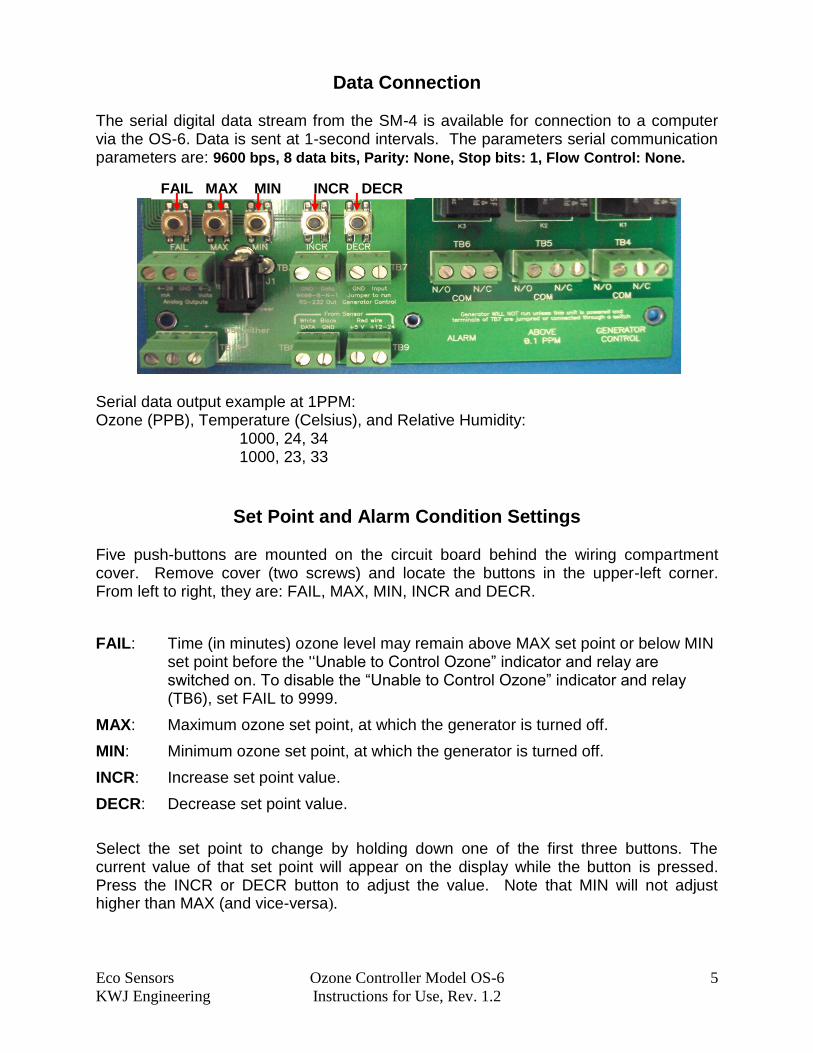
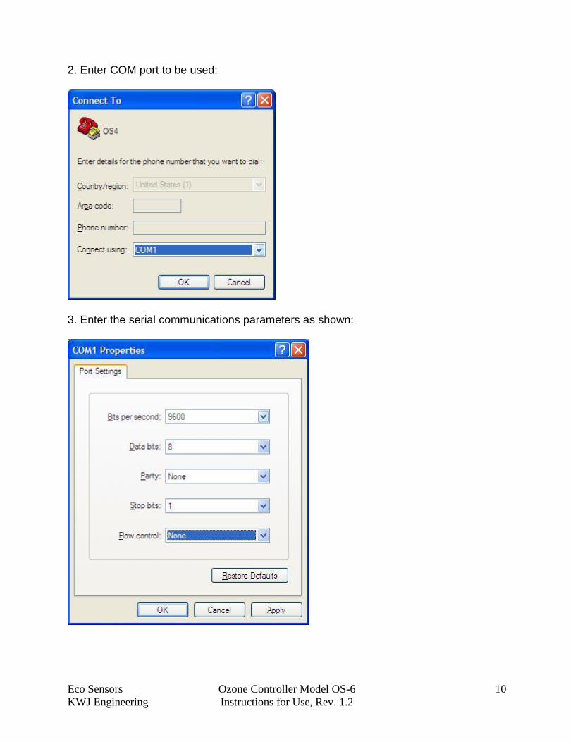
The serial digital data stream from the SM-4 is available for connection to a computer via the OS-6. Data is sent at 1-second intervals. The parameters serial communication parameters are: 9600 bps, 8 data bits, Parity: None, Stop bits: 1, Flow Control: None.
Serial data output example at 1PPM: Ozone (PPB), Temperature (Celsius), and Relative Humidity:
1000, 24, 34 1000, 23, 33
Set Point and Alarm Condition Settings Five push-buttons are mounted on the circuit board behind the wiring compartment cover. Remove cover (two screws) and locate the buttons in the upper-left corner. From left to right, they are: FAIL, MAX, MIN, INCR and DECR.
FAIL: Time (in minutes) ozone level may remain above MAX set point or below MIN set point before the '‘Unable to Control Ozone” indicator and relay are switched on. To disable the “Unable to Control Ozone” indicator and relay (TB6), set FAIL to 9999.
MAX: Maximum ozone set point, at which the generator is turned off.
MIN: Minimum ozone set point, at which the generator is turned off.
INCR: Increase set point value.
DECR: Decrease set point value.
Select the set point to change by holding down one of the first three buttons. The current value of that set point will appear on the display while the button is pressed. Press the INCR or DECR button to adjust the value. Note that MIN will not adjust higher than MAX (and vice-versa).
FAIL MAX MIN INCR DECR

Eco Sensors Ozone Controller Model OS-6 6
KWJ Engineering Instructions for Use, Rev. 1.2
Analog Output PPM Full-Scale Range Selection
Full-scale ranges for the 0-2 V and 4-20 mA analog outputs may be selected by adding or removing up to three push-on jumpers on header J4, which is located on the back of the display circuit board. Access this area by removing four screws from the display bezel.
Jumpers A B C Full-Scale Range selected OFF OFF OFF 0-2 PPM ON OFF OFF 0-5 PPM OFF ON OFF 0-10 PPM ON ON OFF 0-20 PPM ON OFF ON 0-50 PPM ON OFF ON 0-100 PPM OFF ON ON 0-200 PPM ON ON ON 0-500 PPM
IMPORTANT NOTES:
This setting changes only the range of the analog output signal. The OS-6 display will always read 0.000 to 999.9 PPM, to accommodate a range of currently available and future sensor modules.
The range of an OS-6 is limited by the sensor module. The OS-6 is shipped from the factory with the Full Scale Range set to match the installed sensor module. Higher ranges may be available on future sensor modules. Please contact Eco Sensors for details.
Specifications
Enclosure: Wall mounted polycarbonate enclosure resists water spray and splash (NEMA 4X). Size: H = 6.3”/160mm, W = 6.5”/166mm, D = 4.6”/118mm. Wiring: Conduit or cable gland knock-outs along bottom of enclosure. Power in: 12-24 VDC. Power out: +5 or +12-24 VDC to sensor. Data in: RS-232 serial data from remote sensor module (SM-4 or equivalent). Data out: RS-232, 9600 Baud 8N1 format. Analog out: 0-2 V and 4-20 mA, internal jumpers select full scale PPM range. Control in: Generator enable (contact closure). Control outputs: Relays, 10A @ 25VDC, 0.25A @ 250VDC, 2.0 KVA AC (resistor). Relay functions: Ozone generator control, >100 PPB safety limit, failure to control. User controls (internal): MAX set point, MIN set point, FAIL time, increase, decrease. Numeric display: Four digits, 0.5”/12mm, auto-ranging, with backlight. LED indicators: Sensor, above MAX, below MIN, >100 PPB, generator on, failure.
Eco Sensors Ozone Controller Model OS-6 7
KWJ Engineering Instructions for Use, Rev. 1.2
Service and Maintenance
Instruments with problems during the warranty period should be returned as a system (OS-6 and SM-4) to the factory or authorized service representative for diagnosis and repair.
We recommend checking the calibration monthly and replacing the sensor module annually.
Calibration of the sensor on its board (SM-X) is done electronically in a specially constructed facility at the factory. Therefore it is more cost effective to replace the SM-X board than to request that it be recalibrated.
Always remove power from OS-6 and SM-4 before connecting SM-4 to OS-6, or replacing SM-X. Follow Diagram in Appendix A to connect power and SM-4 to OS-6.
Do not attempt to perform board level repairs or microprocessor programming. This will void the warranty. The unit should be returned to Eco Sensors for repairs or performed by an Eco Sensors authorized service representative. Tampering with or attempting repairs to the unit will void the warranty.

Eco Sensors Ozone Controller Model OS-6 8
KWJ Engineering Instructions for Use, Rev. 1.2
Appendix A:
Wiring Illustration – SM-4 to OS-6 (OS-6 Rev 4.0):
CAUTION: TB1 is to be used to connect signal, ground and 5V power from OS-6.If using 12-24V to power SM-4 module, connect power (V+) to TB2. DO NOT connect 12-24 V to TB1, this will damage the SM-4 and void warranty.
TB1
Eco Sensors Ozone Controller Model OS-6 9
KWJ Engineering Instructions for Use, Rev. 1.2
APPENDIX B
CONNECTING OS-6 RS232 OUTPUT TO COMPUTER
Connections: The connections from the OS-6 to the serial COM port of a PC are as follows:
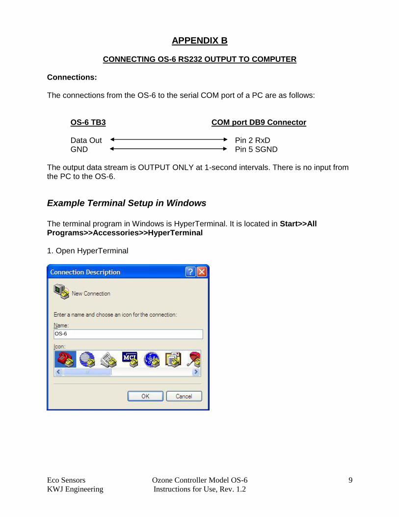
OS-6 TB3 COM port DB9 Connector Data Out Pin 2 RxD GND Pin 5 SGND
The output data stream is OUTPUT ONLY at 1-second intervals. There is no input from the PC to the OS-6.
Example Terminal Setup in Windows
The terminal program in Windows is HyperTerminal. It is located in Start>>All Programs>>Accessories>>HyperTerminal 1. Open HyperTerminal
OS-6
Eco Sensors Ozone Controller Model OS-6 10
KWJ Engineering Instructions for Use, Rev. 1.2
2. Enter COM port to be used:
3. Enter the serial communications parameters as shown:
Eco Sensors Ozone Controller Model OS-6 11
KWJ Engineering Instructions for Use, Rev. 1.2
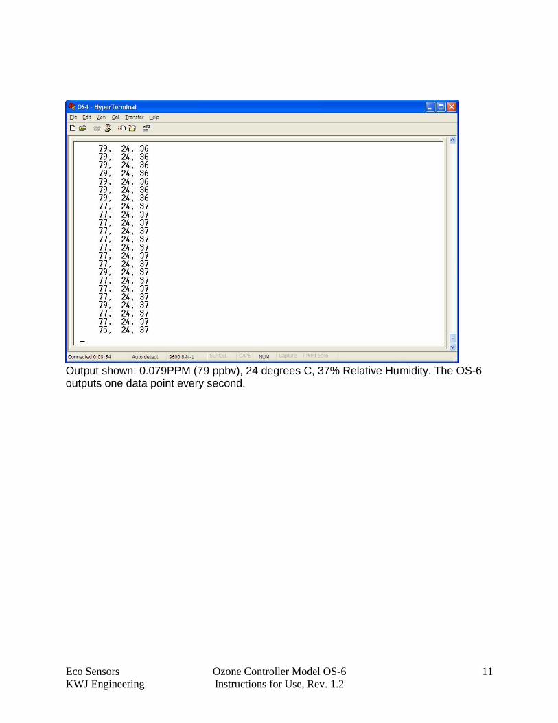
Output shown: 0.079PPM (79 ppbv), 24 degrees C, 37% Relative Humidity. The OS-6 outputs one data point every second.
Eco Sensors Ozone Controller Model OS-6 12
KWJ Engineering Instructions for Use, Rev. 1.2
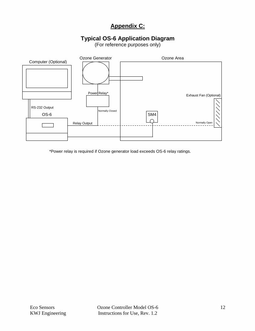
Appendix C:
Typical OS-6 Application Diagram (For reference purposes only)
Ozone Area
OS-6 SM4
Ozone Generator
Relay Output
Power Relay*
*Power relay is required if Ozone generator load exceeds OS-6 relay ratings.
Computer (Optional)
RS-232 Output
Exhaust Fan (Optional)
Normally Closed
Normally Open
Eco Sensors Ozone Controller Model OS-6 13
KWJ Engineering Instructions for Use, Rev. 1.2
WARRANTY This product is warranted against defects in materials and workmanship for one year following the date of purchase by the original owner. This warranty does not include damage to the product that results from misuse, accident, dropping, modifications or alterations, and it does not apply if the instructions in this manual are not followed, or if the unit is otherwise used outside its intended specifications. If a defect develops during the warranty period, Eco Sensors, in its sole discretion, will repair the instrument or replace it with a new or reconditioned model of equivalent quality. In the event of replacement with a new or reconditioned instrument, the replacement unit will continue the warranty of the original unit. If the product should become defective during the warranty period, please return it through your distributor, or call Eco Sensors at (800) 472-6626 or e-mail at [email protected] to receive return instructions and a Return Materials Authorization (RMA) number. Except as provided herein, Eco Sensors makes no warranties, express or implied, including warranties of merchantability and fitness for a particular purpose. Eco Sensors shall not be liable for loss of use of this instrument or other incidental or consequential damages, expenses or economic loss, or claims for such damage or economic loss. RECORD YOUR SERIAL NUMBER HERE__________________________________ KEEP THIS MANUAL AND WARRANTY FOR YOUR RECORDS. Eco Sensors is a registered trademark of Eco Sensors div of KWJ Engineering, Inc. © Eco Sensors div of KWJ Engineering, Inc. 2010. OS-6 REV 2, SM-4 and SM-X, Manual rev 07/10 For brochures, application and tech notes, and other useful information, visit our extensive website at www.ecosensors.com. E-mail us at [email protected].