Embed Size (px)
Citation preview
– 1 – AtlasSound.comSpecifications are subject to change without notice.
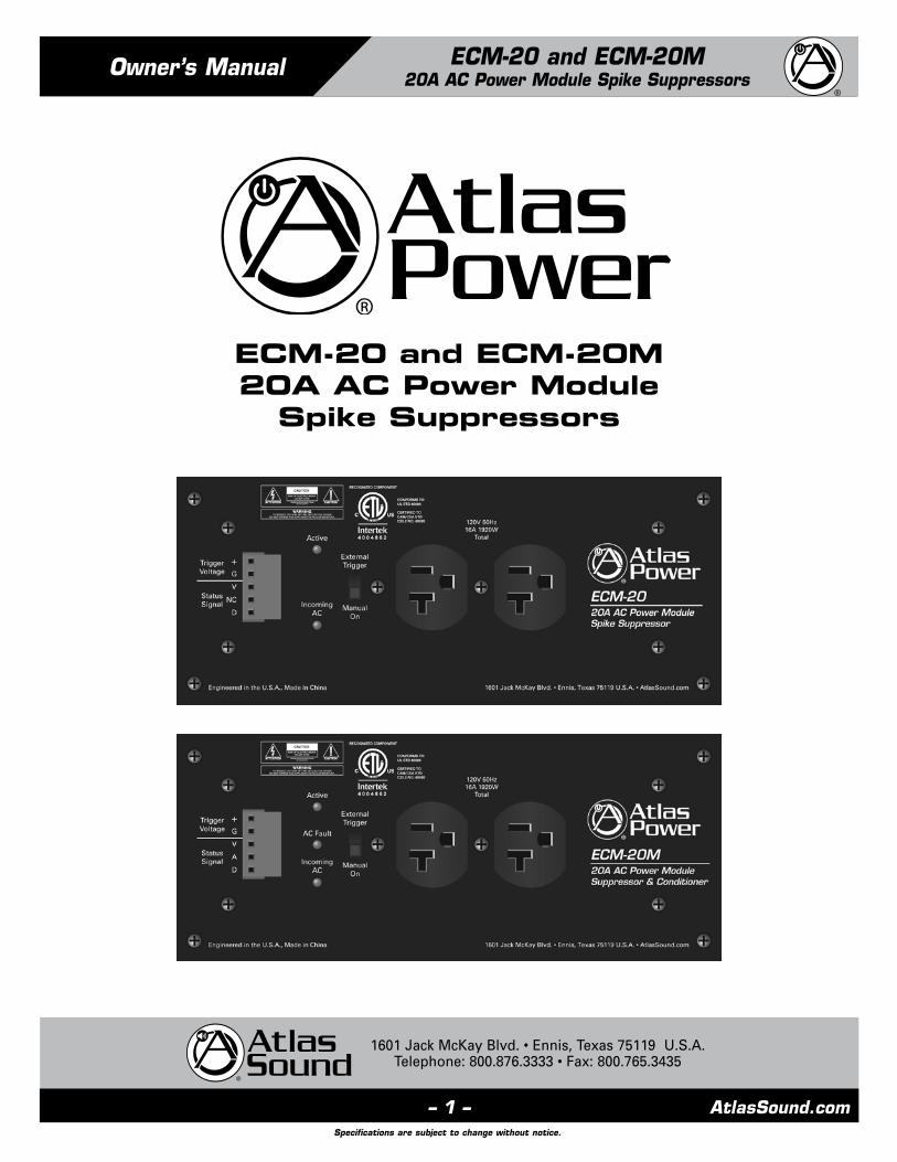
Owner’s Manual ECM-20 and ECM-20M20A AC Power Module Spike Suppressors
1601 Jack McKay Blvd. • Ennis, Texas 75119 U.S.A.Telephone: 800.876.3333 • Fax: 800.765.3435
ECM-20 and ECM-20M20A AC Power Module
Spike Suppressors

AtlasSound.com – 2 –
ECM-20 and ECM-20M20A AC Power Module Spike Suppressors
1601 Jack McKay Blvd. • Ennis, Texas 75119 U.S.A.Telephone: 800.876.3333 • Fax: 800.765.3435
Table of Contents
Important Safety Instructions .................................................................................................................. 3
Introduction ........................................................................................................................................... 5
Key Features .......................................................................................................................................... 5
Applications ............................................................................................................................................ 5
Front Panel Description ........................................................................................................................... 6
ECM Housing Types ................................................................................................................................ 7
ECM Data Wire and Distance ................................................................................................................. 7
ECM Module Activation Without Using an ECS-6RM Controller ........................................................... 8
Wiring the ECM-20/ECM-20M ................................................................................................................ 9
Specifications ....................................................................................................................................... 10
Warranty ................................................................................................................................................ 12

– 3 – AtlasSound.comSpecifications are subject to change without notice.
Owner’s Manual ECM-20 and ECM-20M20A AC Power Module Spike Suppressors
1601 Jack McKay Blvd. • Ennis, Texas 75119 U.S.A.Telephone: 800.876.3333 • Fax: 800.765.3435
Important Safety Instructions
1. Read these instructions.
2. Keep these instructions.
3. Heed all warnings.
4. Follow all instructions.
5. Do not use this device near water.
6. Clean only with dry cloth.
7. Do not block any ventilation openings. Install in accordance with the manufacturer’s instructions.
8. Do not install near any heat sources such as radiators, heat registers, stoves, or other device (including amplifiers)
that produce heat.
9. Do not defeat the safety purpose of the polarized or grounding-type plug. A polarized plug has two blades with one wider than the
other. A grounding type plug has two blades and a third grounding prong. The wide blade or the third prong are provided for your
safety. If the provided plug does not fit into your outlet, consult an electrician for replacement of the obsolete outlet.
10. Protect the power cord from being walked on or pinched particularly at plugs, convenience receptacles, and the point where they
exit from the device.
11. Only use attachments/accessories specified by the manufacturer.
12. Use only with the cart, stand, tripod, bracket, or table specified by the manufacturer, or sold with the device. When a cart is used,
use caution when moving the cart/device combination to avoid injury from tip-over.
13. Unplug this device during lightning storms or when unused for long periods of time.
14. Refer all servicing to qualified service personnel. Servicing is required when the device has been damaged in any way, such as
power-supply cord or plug is damaged, liquid has been spilled, or objects have fallen into the device, the device has been exposed
to rain or moisture, does not operate normally, or has been dropped.
15. WARNING: To reduce the risk of fire or electric shock, this device should not be exposed to rain or moisture and objects filled with
liquids, such as a vase, should not be placed on this device.
16. To completely disconnect this equipment from the mains, disconnect the power supply cord plug from the receptacle.
17. The mains plug of the power supply cord shall remain readily operable.
The lightning flash with arrowhead symbol within anequilateral triangle, is intended to alert the user to thepresence of uninsulated “dangerous voltage “ within the product’s enclosure that may be of sufficient magnitudeto constitute a risk of electric shock to persons.
The exclamation point within an equilateral triangle isintended to alert the user to the presence of importantoperating and maintenance (servicing) instructions in the literature accompanying the product.

AtlasSound.com – 4 –
ECM-20 and ECM-20M20A AC Power Module Spike Suppressors
1601 Jack McKay Blvd. • Ennis, Texas 75119 U.S.A.Telephone: 800.876.3333 • Fax: 800.765.3435
When The Device Is In Use
• To prevent electric shock, do not remove the product cover as there are high voltage components inside. Refer all servicing to
Atlas Sound.
• Should any of the following irregularities occur during use, immediately switch off the power, disconnect the power cord from the
AC outlet and contact Atlas Sound. Do not to attempt to continue operation with the product as this may cause fire or electric shock:
• Smoke or strange smell coming from the unit.
• If the product falls or the case is damaged.
• If water or any metallic objects falls into the product.
• If the power supply cord is damaged in any way.
• If the unit is malfunctioning.
• Do not insert or drop metallic objects or flammable materials into the ventilation holes of the product's cover, as this may result in
electric shock or fire.
• Do not place any containers with liquid or metallic objects on the top of the product. If any liquid spills into the unit, fire or electric
shock may result.
• Never operate this product or touch the power supply cord during an electrical storm, electric shock may result.
• Never exceed the power rating on the product when connecting equipment. Fire and/or property damage may result.
• Operate the product only with the voltage specified on the unit. Fire and/or electric shock may result if a higher voltage is used.
• Do not modify, kink, or cut the power cord. Do not place the power cord in close proximity to heaters and do not place heavy objects
on the power cord, including the product itself, doing so may result in fire or electrical shock.
• Ensure that the safety ground terminal is connected to a proper ground. Never connect the ground to a gas pipe as a catastrophic
disaster may result.
• Be sure the installation of the product is stable, avoid slanted surfaces as the product may fall and cause injury or property damage.
When Installing The Product
• Installation of this product must be done by a certified electrician for a permanently connected apparatus provided neither with an
all-pole mains switch nor an all-pole circuit breaker. A readily accessible disconnect device shall be incorporated in the building
installation power wiring. The installation shall be carried out in accordance with all applicable installation rules in accordance with all
applicable federal, state, and local laws, regulations, and safety codes and ordinances.
• Never install this product in humid or dusty locations, nor in direct sunlight, near sources of heat, or in areas where sooty smoke or
steam are present. Fire and electric shock may result.
• Keep all sides of the unit at least 31⁄2" away from objects that may obstruct air flow to prevent the unit's internal temperature rise.
When The Product Is In Use
• Never place heavy objects on the product, causing it to fall and/or break, resulting in personal injury and property damage. In
addition, the product itself may fall and cause injury and property damage.
• Contact Atlas Sound for instructions on cleaning the inside of the unit. Large accumulations of dust inside the unit may result in heat
buildup and fire.
• Ensure that the power supply plug is securely plugged into the wall outlet. Never allow dust to accumulate on the power plug or
inside the wall outlet.
• When cleaning the unit or the unit is not to be operated for an extended period, unplug the power cord from the wall.
CAUTION
WARNING
CAUTION

– 5 – AtlasSound.comSpecifications are subject to change without notice.
Owner’s Manual ECM-20 and ECM-20M20A AC Power Module Spike Suppressors
1601 Jack McKay Blvd. • Ennis, Texas 75119 U.S.A.Telephone: 800.876.3333 • Fax: 800.765.3435
Introduction
Thank you for purchasing the Atlas Power Electrical Control Module Raceway system. This information sheet is an overview of the
ECM-20/ECM-20M control module. Please refer to the ECM-RACEWY6/ECM-20/ECM-20M manual for full details on features and ECM
module installation. Note: For your safety all electrical wiring must be done by a qualified electrician.
The Atlas Power ECM-20/ECM-20M is a Electrical Control Module (ECM) 20A Power Conditioner and AC Spike Suppressor that is
designed to be used as a standalone unit or in conjunction with an ECS-6RM Controller up to 1000 ft away. AC Spikes, or Transients,
are commonly caused by utility power plant grid switchovers. The amount of energy that can be injected into the power system can
be immense with voltages reaching 6kV or amperage peaks of 3000A. These spikes are very fast and usually only last for a very
short period of time. To protect against this potential problem, incoming AC Mains have special suppression circuitry to eliminate the
unwanted energy. This circuitry is very fast and can suppress unwanted energy within a nanosecond, while sustaining the suppression
for up to 2 milliseconds, thus ensuring virtually trouble free protection. High and low AC Main line voltages are another major
contributor to equipment failures. The ECM modules support EVS circuitry which enables the module to be shut off during Low and
High AC Line conditions.
The ECM-20M features noise filtering for unwanted Radio Frequency Interference (RFI) and Electromagnetic Interference (EMI) filters
to reduce noise from such items as electric motors and switching power supplies. The benefit of these filters can be seen on video
products or audibly by reducing static pops and external signal interference.
High line can also be known as surges. Surges usually are a slower steady state rise in voltages ranging from 128VAC and up. They can
be caused from fluctuations from the utility company’s power lines or industrial equipment turning On and Off, and are on the same
power leg of the building’s incoming AC.
Low line is also known as brownouts. This happens when the AC Mains drops below 107VAC. Most of the time it is caused by the
utility company not being able to supply enough power during heavy utility consumption time periods, such as heat waves. Another
factor can be from voltage drops in AC lines due to long transmissions. The ECS-6RM will inform you if any of these conditions occur.
Extreme variances in Unstable AC Mains voltage are one of the main reasons for equipment failure.
The ECM-20 does not support the same current monitoring or EMI/RFI Filter features as the ECM-20M, ECM-20SH and the
ECM-15SH models do. However, it does support AC Spike and Surge Suppression, AC Mains Voltage monitoring, EVS circuitry and
Remote Activation.
Key Features
• Manual/Auto On/Off Switch
• Incoming AC Present LED
• Active LED
• AC Fault LED (ECM-20M Only)
• Clamping Spike & Surge Suppression EVS Circuitry
• AC Mains Voltage & Current monitoring (Voltage only for ECM-20)
• EMI & RFI Filtering (ECM-20M Only)
Applications
The following are just a few examples of applications where the ECM-20/ECM-20M can be used:
• Restaurants
• Houses of Worship
• Schools
• Home Theaters
• Office Buildings
• Sports Bars
• Industrial Facilities

AtlasSound.com – 6 –
ECM-20 and ECM-20M20A AC Power Module Spike Suppressors
1601 Jack McKay Blvd. • Ennis, Texas 75119 U.S.A.Telephone: 800.876.3333 • Fax: 800.765.3435
Front Panel
1. Trigger/Status Port Pin Identification
All signals are of low voltage and current. DO NOT MISS WIRE or damage may occur.
A. (+) requires a minimum of 5–24V DC to activate the module with 5mA of current. Note: The DCV can be supplied from any
source. The EVS protection requires the ECS-6RM for operation.
B. G = Circuit Ground. Must be of the same circuit as the DCV source.
C. V = AC Voltage Status Signal. Reports the Incoming AC Mains Voltage to the ECM module back to the ECS-6RM.
D. A = AC Current Status Signal. Reports the AC Mains Current Draw to the ECM module back to the ECS-6RM. Note: Not
available with the ECM-20.
E. D = Fault Status Signal. Reports any fault conditions of an ECM module to the ECS-6RM.
2. External Trigger/Manual On Switch
The ECM-20/ECM-20M has a manual override switch allowing it to be used as a local Spike Suppressor. For remote monitoring and
activation, the switch must be in the “External Trigger” position.
3. Active LED
This LED will illuminate Green when the ECM module has sensed the proper DCV to activate the unit. Note: If connected to the
ECS-6RM and the EVS circuit has been activated, this LED will not be lit. The Channel Status LED on the ECS-6RM will flash indicating
a problem and the ECM module will not turn On until the AC Mains voltage is stable.
4. AC Fault LED
If damage to the Spike Suppression circuit occurs, this LED will illuminate Red. The module may still operate but may not be
protecting the items plugged into the AC outlets. The ECM module should be inspected and repaired by a qualified technician.
Note: Not available with the ECM-20.
5. Incoming AC LED
This LED will illuminate Red when the ECM has incoming AC power present at the module. This LED must be On to operate.
Note: If this LED is not illuminating check the following: 1) the unit is plugged in, 2) the AC Mains Breaker feeding the AC leg to the
ECM module is Off, 3) the internal fuse has been damaged. This should only be inspected by an authorized technician.
6. AC Mains Outlet
Two 120V AC 20A outlets.
1 12 25 5
3 346 6

– 7 – AtlasSound.comSpecifications are subject to change without notice.
Owner’s Manual ECM-20 and ECM-20M20A AC Power Module Spike Suppressors
1601 Jack McKay Blvd. • Ennis, Texas 75119 U.S.A.Telephone: 800.876.3333 • Fax: 800.765.3435
ECM Housing Types
The ECM-20/ECM-20M requires an electrical housing. The ECM-RACEWY1 holds 1 ECM module, the ECM-RACEWY3 holds up to 3
ECM modules, and the ECM-RACEWY6 housed up to 6 ECM modules. Three standard ¾" and 1" electrical knockouts on the bottom
of each raceway and a distribution area with cover plate supports standard electrical mounting hardware. Note: All electrical wiring
should be done by a certified electrician.
ECM-3BP Module Cover Plate
The ECM-RACEWY3 can hold up to three ECM-20/ECM-20M Modules and the ECM-RACEWY6 can hold up to six ECM-20/ECM-20M
Modules. If using fewer modules than the housing will hold, the open slots can be covered using an ECM Module Blank Plate. Two of
these are included with the ECM-RACEWY6. If additional Blank Plates are required, they can be purchased in packages of three.
All cover plates must be secured tightly. For safety, there should be no open slots when the raceway is in use. Top and bottom
mounting tabs are incorporated to mount inside an Atlas Rack. All rack mount rails are designed to be removed if they are not needed.
Simply bend the tab back and forth until the tab breaks. Be careful of sharp edges.
ECM Data Wire and Distance
There are six ECM control ports on the ECS-6RM and up to six ECM Modules can be connected to it. There are many types of ECM
Modules that require the same interface connectivity to the ECS-6RM. All ECM Modules can be interfaced with the ECS-6RM.
For connection between the ECS-6RM and an ECM module, use a 5 conductor cable that is a minimum of 22 gauge wire. It is
recommended to use CAT5 cable due to the common availability and low cost. Pay special attention to the port connections and DO NOT MISS WIRE or damage may occur. The distance between the ECS-6RM and the ECM Module can be up to 1000ft.
ECM-RACEWY1
ECM-RACEWY1
ECM-RACEWY6
ECM-RACEWY3
ECM-RACEWY3

AtlasSound.com – 8 –
ECM-20 and ECM-20M20A AC Power Module Spike Suppressors
1601 Jack McKay Blvd. • Ennis, Texas 75119 U.S.A.Telephone: 800.876.3333 • Fax: 800.765.3435
ECM Module Activation without using an ECS-6RM Controller
Any of the ECM Modules can be triggered remotely to activate without using an ECS type Controller. If you do not need the features of
the ECS controllers, remote activation can be accomplished by applying DC external voltage or by hard switch contacts. Note: The EVS
and Voltage monitoring will be disabled when not using an ECS controller.
Remote DC Voltage Trigger
(+) requires a minimum of 5–24VDC to activate the module with 5mA of current. The DVC can be supplied from any source. Note: The EVS and Voltage monitoring will be disabled
G=Circuit Ground. Must be of the same circuit as the DCV source.
Remote Hard Switch Contact Trigger
An external hard switch will also activate an ECM module by applying a contact to short terminals “+” and “D” together. Note: The EVS and Voltage monitoring will be disabled.

– 9 – AtlasSound.comSpecifications are subject to change without notice.
Owner’s Manual ECM-20 and ECM-20M20A AC Power Module Spike Suppressors
1601 Jack McKay Blvd. • Ennis, Texas 75119 U.S.A.Telephone: 800.876.3333 • Fax: 800.765.3435
Wiring the ECM-20/ECM-20M Control Module
The ECM-20/ECM-20M is designed to be inserted in the ECM-RACEWY1, ECM-RACEWY3, or ECM-RACEWY6 housing. The specific job
(install) AC power requirements and power distribution layout will dictate how the ECM modules are wired into the housing. Each ECM
module can be wired as a single 20A run or in a parallel (loop thru) configuration. Each ECM module has dual 3-position screw terminal
blocks that are in parallel and are clearly labeled as follow: E - Green = Ground, L - Black = Load, N - White = Neutral. Follow all local
electrical codes. All installation must be done by a certified electrician.
Note: The figures above show the ECM wiring configuration of one 20A AC main line coming into an ECM-20M, then paralleling with an
ECM-20 type module. It appears that the wiring is in series but the ECM Module In/Out terminals are in parallel on the PCB.

AtlasSound.com – 10 –
ECM-20 and ECM-20M20A AC Power Module Spike Suppressors
1601 Jack McKay Blvd. • Ennis, Texas 75119 U.S.A.Telephone: 800.876.3333 • Fax: 800.765.3435
ECM-20/ECM-20M Specifications
Type AC Power Module Spike Suppressor
RoHS Compliant Yes
Safety Listings ETL (UL 60065 Standard)
Front Panel
Outlet Two 20A
Indicators Active (Green), Fault (Red) (ECM-20M Only), Incoming AC (Red)
Manual Override Slide Switch
Connectors 5 Position Phoenix Euro Block Style
Hard Switch Remote Trigger SPST Contact
Status Signals Output for Voltage and Current Data (ECM-20M Only)
AC Mains Interconnect Screw Terminal Block
Technical Data
Current Rating 15A
Operating Voltage 102VAC - 132VAC
Power Consumption 500 milliwatts
Power Requirements 120V 60Hz
Extreme Voltage Shutdown (EVS) Below 102V or above 132V AC Line (When used with ECM-6RM) (ECM-20M Only)
DCV Remote Trigger 5-24DCV
High Voltage Surge Protection Trigger at 133VAC, 1ms typically (When used with ECS-6RM) (ECM-20M Only)
Low Voltage Surge Protection Trigger at 101VAC, 1ms typically (When used with ECS-6RM) (ECM-20M Only)
Spike and Surge Suppression Hot to Neutral, Hot to Ground, Neutral to Ground
Spike Protection Modes Circuitry on Incoming AC Mains
Min. Spike Clamping Voltage 460 VRMS @ 3,000 amps
Max. Spike Clamping Voltage 6kV
Max. Spike Clamping Resp. Time <1 nanosecond
Spike Clamping Voltage @ 100A 1,250Vp for 20µs
Maximum Surge Current 6,500A
Energy Rating 600 Joules
Temperature Range 5° – 35°C
Humidity Range 5% to 95% R.H.
Mechanical
Chassis Finish Black
Mounting #8 5⁄16" Self Tapping Screws
Height 3" (76.2mm)
Width 3.5" (88.9mm)
Length 8.5" (215.9mm)
Weight ECM-20: 1.25 lbs (0.68kg), ECM-20M: 1.75 lbs (.80kg)

– 11 – AtlasSound.comSpecifications are subject to change without notice.
Owner’s Manual ECM-20 and ECM-20M20A AC Power Module Spike Suppressors
1601 Jack McKay Blvd. • Ennis, Texas 75119 U.S.A.Telephone: 800.876.3333 • Fax: 800.765.3435
Notes:

AtlasSound.com – 12 –
ECM-20 and ECM-20M20A AC Power Module Spike Suppressors
1601 Jack McKay Blvd. • Ennis, Texas 75119 U.S.A.Telephone: 800.876.3333 • Fax: 800.765.3435
Limited Warranty
All products manufactured by Atlas Sound are warranted to the original dealer/installer, industrial or commercial purchaser to be free
from defects in material and workmanship and to be in compliance with our published specifications, if any. This warranty shall extend
from the date of purchase for a period of three years on all Atlas Sound products, including SOUNDOLIER brand, and ATLAS SOUND
brand products except as follows: one year on electronics and control systems; one year on replacement parts; and one year on
Musician Series stands and related accessories. Additionally, fuses and lamps carry no warranty. Atlas Sound will solely at its discretion,
replace at no charge or repair free of charge defective parts or products when the product has been applied and used in accordance
with our published operation and installation instructions. We will not be responsible for defects caused by improper storage, misuse
(including failure to provide reasonable and necessary maintenance), accident, abnormal atmospheres, water immersion, lightning
discharge, or malfunctions when products have been modified or operated in excess of rated power, altered, serviced or installed
in other than a workman like manner. The original sales invoice should be retained as evidence of purchase under the terms of this
warranty. All warranty returns must comply with our returns policy set forth below. When products returned to Atlas Sound do not
qualify for repair or replacement under our warranty, repairs may be performed at prevailing costs for material and labor unless there is
included with the returned product(s) a written request for an estimate of repair costs before any nonwarranty work is performed. In
the event of replacement or upon completion of repairs, return shipment will be made with the transportation charges collect.
EXCEPT TO THE EXTENT THAT APPLICABLE LAW PREVENTS THE LIMITATION OF CONSEQUENTIAL DAMAGES FOR PERSONAL
INJURY, ATLAS SOUND SHALL NOT BE LIABLE IN TORT OR CONTRACT FOR ANY DIRECT, CONSEQUENTIAL OR INCIDENTAL
LOSS OR DAMAGE ARISING OUT OF THE INSTALLATION, USE OR INABILITY TO USE THE PRODUCTS. THE ABOVE WARRANTY IS
IN LIEU OF ALL OTHER WARRANTIES INCLUDING BUT NOT LIMITED TO WARRANTIES OF MERCHANTABILITY AND FITNESS FOR
A PARTICULAR PURPOSE.
Atlas Sound does not assume, or does it authorize any other person to assume or extend on its behalf, any other warranty, obligation,
or liability. This warranty gives you specific legal rights and you may have other rights which vary from state to state.
Service
Should your ECM-20/ECM-20M require service, please contact the Atlas Sound warranty department at
1-877-689-8055, ext. 277 to obtain an RA number.
Atlas Sound Tech Support can be reached at 1-800-876-3333.
Visit our website at www.AtlasSound.com to see other Atlas products.
©2012 Atlas Sound L.P. All rights reserved. Atlas Sound is a trademark of Atlas Sound L.P. All other trademarks are the property of their respective owners. ATS003544 RevB 3/12