Embed Size (px)
Citation preview

ENERGY ·CONTROL· SYSTEMECL Interpreter and Command List
3-348-870-0310/12.14
Command Reference
2 GMC-I Messtechnik GmbH
Table of Contents Page
1 ECL Interpreter . . . . . . . . . . . . . . . . . . . . . . . . . . . . . . . . . . . . . . . . . . . . . . . . . . . . . . . . . . . 31.1 Introduction . . . . . . . . . . . . . . . . . . . . . . . . . . . . . . . . . . . . . . . . . . . . . . . . . . . . . . . . . . . . . . 31.2 Value Range, Numbers and Character Strings . . . . . . . . . . . . . . . . . . . . . . . . . . . . . . . . . . . . . . 51.3 Arguments, Extensions, Assignments and Error Messages . . . . . . . . . . . . . . . . . . . . . . . . . . . . . 61.4 Aborting Programs . . . . . . . . . . . . . . . . . . . . . . . . . . . . . . . . . . . . . . . . . . . . . . . . . . . . . . . . . 81.5 The System Prompt and Online Help . . . . . . . . . . . . . . . . . . . . . . . . . . . . . . . . . . . . . . . . . . . . . 81.6 Overview of ECL Command Groups . . . . . . . . . . . . . . . . . . . . . . . . . . . . . . . . . . . . . . . . . . . . 101.7 Tool Box (Examples of use) . . . . . . . . . . . . . . . . . . . . . . . . . . . . . . . . . . . . . . . . . . . . . . . . . . 11
2 ECL Command List . . . . . . . . . . . . . . . . . . . . . . . . . . . . . . . . . . . . . . . . . . . . . . . . . . . . . . . 172.1 General Information . . . . . . . . . . . . . . . . . . . . . . . . . . . . . . . . . . . . . . . . . . . . . . . . . . . . . . . . 172.2 Command List . . . . . . . . . . . . . . . . . . . . . . . . . . . . . . . . . . . . . . . . . . . . . . . . . . . . . . . . . . . 232.3 Command Equivalents . . . . . . . . . . . . . . . . . . . . . . . . . . . . . . . . . . . . . . . . . . . . . . . . . . . . . . 87
3 Parameter Search Terms . . . . . . . . . . . . . . . . . . . . . . . . . . . . . . . . . . . . . . . . . . . . . . . . . . 89
4 Product Support Industrial Division . . . . . . . . . . . . . . . . . . . . . . . . . . . . . . . . . . . . . . . . . . . 92
ECS operating system revision level: V2.54
GMC-I Messtechnik GmbH 3
1 ECL Interpreter
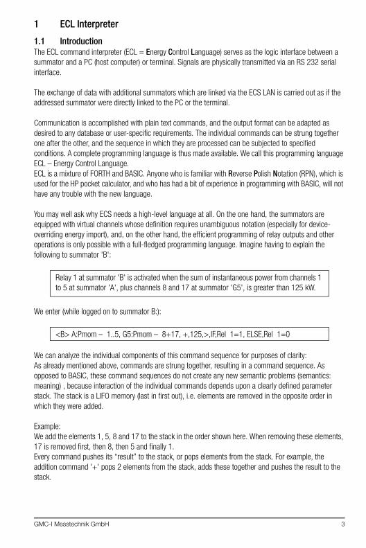
1.1 IntroductionThe ECL command interpreter (ECL = Energy Control Language) serves as the logic interface between a summator and a PC (host computer) or terminal. Signals are physically transmitted via an RS 232 serial interface.
The exchange of data with additional summators which are linked via the ECS LAN is carried out as if the addressed summator were directly linked to the PC or the terminal.
Communication is accomplished with plain text commands, and the output format can be adapted as desired to any database or user-specific requirements. The individual commands can be strung together one after the other, and the sequence in which they are processed can be subjected to specified conditions. A complete programming language is thus made available. We call this programming language ECL – Energy Control Language.ECL is a mixture of FORTH and BASIC. Anyone who is familiar with Reverse Polish Notation (RPN), which is used for the HP pocket calculator, and who has had a bit of experience in programming with BASIC, will not have any trouble with the new language.
You may well ask why ECS needs a high-level language at all. On the one hand, the summators are equipped with virtual channels whose definition requires unambiguous notation (especially for device-overriding energy import), and, on the other hand, the efficient programming of relay outputs and other operations is only possible with a full-fledged programming language. Imagine having to explain the following to summator 'B':
We enter (while logged on to summator B:):
We can analyze the individual components of this command sequence for purposes of clarity:As already mentioned above, commands are strung together, resulting in a command sequence. As opposed to BASIC, these command sequences do not create any new semantic problems (semantics: meaning) , because interaction of the individual commands depends upon a clearly defined parameter stack. The stack is a LIFO memory (last in first out), i.e. elements are removed in the opposite order in which they were added.
Example:We add the elements 1, 5, 8 and 17 to the stack in the order shown here. When removing these elements, 17 is removed first, then 8, then 5 and finally 1.Every command pushes its “result” to the stack, or pops elements from the stack. For example, the addition command '+' pops 2 elements from the stack, adds these together and pushes the result to the stack.
Relay 1 at summator 'B' is activated when the sum of instantaneous power from channels 1 to 5 at summator 'A', plus channels 8 and 17 at summator 'G5', is greater than 125 kW.
<B> A:Pmom – 1..5, G5:Pmom – 8+17, +,125,>,IF,Rel 1=1, ELSE,Rel 1=0
4 GMC-I Messtechnik GmbH
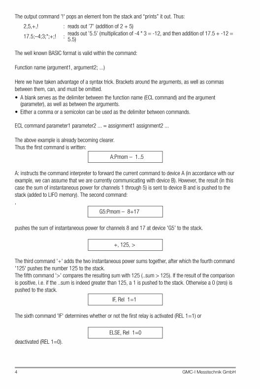
The output command '!' pops an element from the stack and “prints” it out. Thus:
The well known BASIC format is valid within the command:
Function name (argument1, argument2; ...)
Here we have taken advantage of a syntax trick. Brackets around the arguments, as well as commas between them, can, and must be omitted.• A blank serves as the delimiter between the function name (ECL command) and the argument
(parameter), as well as between the arguments.• Either a comma or a semicolon can be used as the delimiter between commands.
ECL command parameter1 parameter2 ... = assignment1 assignment2 ...
The above example is already becoming clearer. Thus the first command is written:
A: instructs the command interpreter to forward the current command to device A (in accordance with our example, we can assume that we are currently communicating with device B). However, the result (in this case the sum of instantaneous power for channels 1 through 5) is sent to device B and is pushed to the stack (added to LIFO memory). The second command:,
pushes the sum of instantaneous power for channels 8 and 17 at device 'G5' to the stack.
The third command '+' adds the two instantaneous power sums together, after which the fourth command '125' pushes the number 125 to the stack.The fifth command '>' compares the resulting sum with 125 (..sum > 125). If the result of the comparison is positive, i.e. if the ..sum is indeed greater than 125, a 1 is pushed to the stack. Otherwise a 0 (zero) is pushed to the stack.
The sixth command 'IF' determines whether or not the first relay is activated (REL 1=1) or
deactivated (REL 1=0).
2,5,+,! : reads out ’7’ (addition of 2 + 5)
17.5;–4;3;*;+;! : reads out ’5.5’ (multiplication of -4 * 3 = -12, and then addition of 17.5 + -12 = 5.5)
A:Pmom – 1..5
G5:Pmom – 8+17
+, 125, >
IF, Rel 1=1
ELSE, Rel 1=0
GMC-I Messtechnik GmbH 5
1.2 Value Range, Numbers and Character StringsNumeric data which occur at the summators may encompass a very broad range. However, accuracy is of greater significance than the extent of the value range, and accuracy is expressed here in the form of significant decimal places. 15 significant decimal places are available, and the value range which can be represented within the interpreter encompasses 27 places before, and 9 places after the decimal point.
Note
If 15 places are insufficient for the representation of a number, exponential notation is activated internally (64 bit floating decimal point).
For example, the following energy value can be processed without sacrificing any accuracy:
1,234,567,890.12345 kWh
All calculation operations which are made available by the interpreter comply with the specified accuracy.
We can use the designation REAL for this data type, even though a comparison with real numbers is somewhat lacking. At any rate, we should make a note of the following: The interpreter only recognizes this one data type where numbers are concerned. Integer values represent a sub-group of REAL (with the exception of enumerations, e.g. 1..4+7).
Remember:The parameter stack only accepts elements of the REAL type.
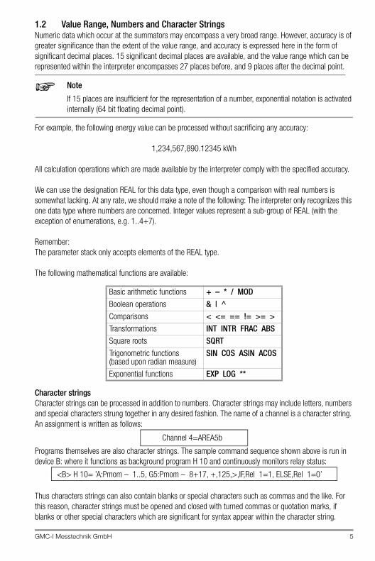
The following mathematical functions are available:
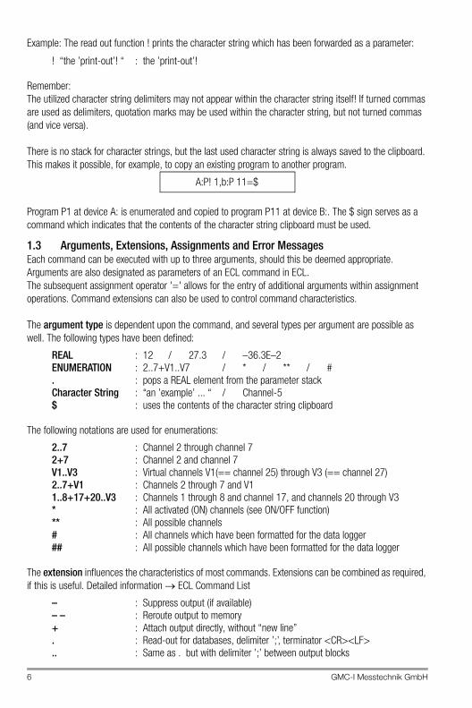
Character stringsCharacter strings can be processed in addition to numbers. Character strings may include letters, numbers and special characters strung together in any desired fashion. The name of a channel is a character string. An assignment is written as follows:
Programs themselves are also character strings. The sample command sequence shown above is run in device B: where it functions as background program H 10 and continuously monitors relay status:
Thus characters strings can also contain blanks or special characters such as commas and the like. For this reason, character strings must be opened and closed with turned commas or quotation marks, if blanks or other special characters which are significant for syntax appear within the character string.
Basic arithmetic functions + – * / MODBoolean operations & | ^Comparisons < <= == != >= >Transformations INT INTR FRAC ABSSquare roots SQRTTrigonometric functions(based upon radian measure)
SIN COS ASIN ACOS
Exponential functions EXP LOG **
Channel 4=AREA5b
<B> H 10= ’A:Pmom – 1..5, G5:Pmom – 8+17, +,125,>,IF,Rel 1=1, ELSE,Rel 1=0’
6 GMC-I Messtechnik GmbH
Example: The read out function ! prints the character string which has been forwarded as a parameter:
Remember:The utilized character string delimiters may not appear within the character string itself! If turned commas are used as delimiters, quotation marks may be used within the character string, but not turned commas (and vice versa).
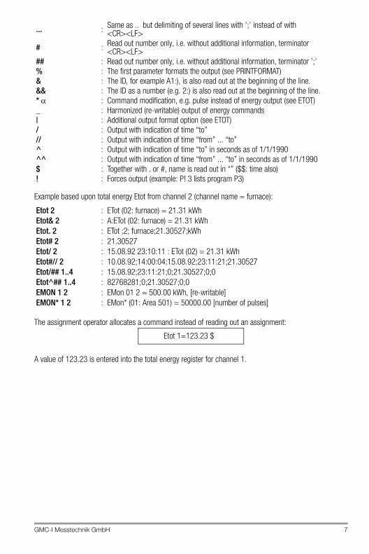
There is no stack for character strings, but the last used character string is always saved to the clipboard. This makes it possible, for example, to copy an existing program to another program.
Program P1 at device A: is enumerated and copied to program P11 at device B:. The $ sign serves as a command which indicates that the contents of the character string clipboard must be used.
1.3 Arguments, Extensions, Assignments and Error MessagesEach command can be executed with up to three arguments, should this be deemed appropriate. Arguments are also designated as parameters of an ECL command in ECL.The subsequent assignment operator '=' allows for the entry of additional arguments within assignment operations. Command extensions can also be used to control command characteristics.
The argument type is dependent upon the command, and several types per argument are possible as well. The following types have been defined:
The following notations are used for enumerations:
The extension influences the characteristics of most commands. Extensions can be combined as required, if this is useful. Detailed information ECL Command List
! “the ’print-out’! “ : the ’print-out’!
REAL : 12 / 27.3 / –36.3E–2ENUMERATION : 2..7+V1..V7 / * / ** / #. : pops a REAL element from the parameter stackCharacter String : “an ’example’ ... “ / Channel-5$ : uses the contents of the character string clipboard
2..7 : Channel 2 through channel 72+7 : Channel 2 and channel 7V1..V3 : Virtual channels V1(== channel 25) through V3 (== channel 27)2..7+V1 : Channels 2 through 7 and V11..8+17+20..V3 : Channels 1 through 8 and channel 17, and channels 20 through V3* : All activated (ON) channels (see ON/OFF function)** : All possible channels# : All channels which have been formatted for the data logger## : All possible channels which have been formatted for the data logger
– : Suppress output (if available)– – : Reroute output to memory+ : Attach output directly, without “new line”. : Read-out for databases, delimiter ’;’, terminator <CR><LF>.. : Same as . but with delimiter ’;’ between output blocks
A:P! 1,b:P 11=$
GMC-I Messtechnik GmbH 7
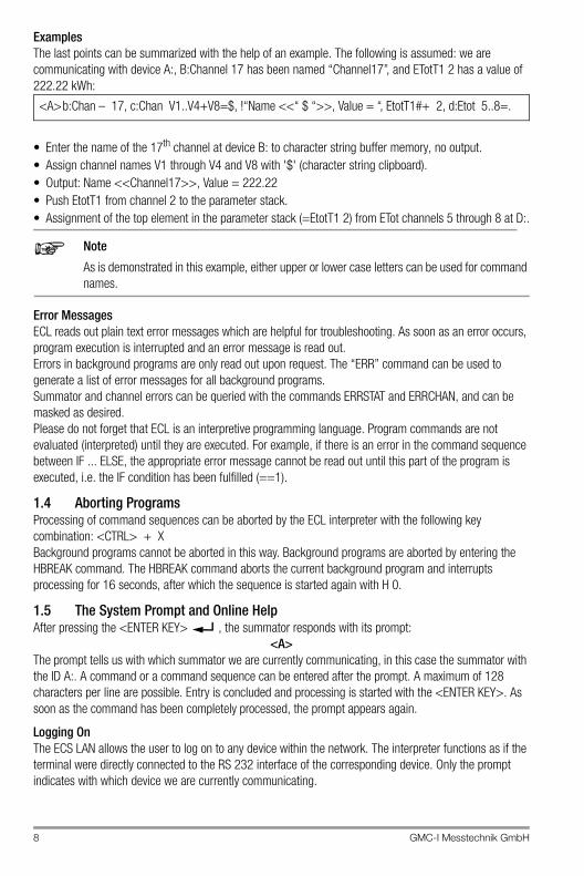
Example based upon total energy Etot from channel 2 (channel name = furnace):
The assignment operator allocates a command instead of reading out an assignment:
A value of 123.23 is entered into the total energy register for channel 1.
... : Same as .. but delimiting of several lines with ’;’ instead of with <CR><LF>
# : Read out number only, i.e. without additional information, terminator <CR><LF>
## : Read out number only, i.e. without additional information, terminator ’;’% : The first parameter formats the output (see PRINTFORMAT)& : The ID, for example A1:), is also read out at the beginning of the line.&& : The ID as a number (e.g. 2:) is also read out at the beginning of the line.* : Command modification, e.g. pulse instead of energy output (see ETOT)_ : Harmonized (re-writable) output of energy commands| : Additional output format option (see ETOT)/ : Output with indication of time “to”// : Output with indication of time “from” ... “to”^ : Output with indication of time “to” in seconds as of 1/1/1990^^ : Output with indication of time “from” ... “to” in seconds as of 1/1/1990$ : Together with . or #, name is read out in “” ($$: time also)! : Forces output (example: P! 3 lists program P3)
Etot 2 : ETot (02: furnace) = 21.31 kWhEtot& 2 : A:ETot (02: furnace) = 21.31 kWhEtot. 2 : ETot ;2; furnace;21.30527;kWhEtot# 2 : 21.30527Etot/ 2 : 15.08.92 23:10:11 : ETot (02) = 21.31 kWhEtot#// 2 : 10.08.92;14:00:04;15.08.92;23:11:21;21.30527Etot/## 1..4 : 15.08.92;23:11:21;0;21.30527;0;0Etot^## 1..4 : 82768281;0;21.30527;0;0EMON 1 2 : EMon 01 2 = 500.00 kWh, [re-writable]EMON* 1 2 : EMon* (01: Area 501) = 50000.00 [number of pulses]
Etot 1=123.23 $
8 GMC-I Messtechnik GmbH
ExamplesThe last points can be summarized with the help of an example. The following is assumed: we are communicating with device A:, B:Channel 17 has been named “Channel17”, and ETotT1 2 has a value of 222.22 kWh:
• Enter the name of the 17th channel at device B: to character string buffer memory, no output.• Assign channel names V1 through V4 and V8 with '$' (character string clipboard).• Output: Name <<Channel17>>, Value = 222.22• Push EtotT1 from channel 2 to the parameter stack.• Assignment of the top element in the parameter stack (=EtotT1 2) from ETot channels 5 through 8 at D:.
Note
As is demonstrated in this example, either upper or lower case letters can be used for command names.
Error MessagesECL reads out plain text error messages which are helpful for troubleshooting. As soon as an error occurs, program execution is interrupted and an error message is read out.Errors in background programs are only read out upon request. The “ERR” command can be used to generate a list of error messages for all background programs.Summator and channel errors can be queried with the commands ERRSTAT and ERRCHAN, and can be masked as desired.Please do not forget that ECL is an interpretive programming language. Program commands are not evaluated (interpreted) until they are executed. For example, if there is an error in the command sequence between IF ... ELSE, the appropriate error message cannot be read out until this part of the program is executed, i.e. the IF condition has been fulfilled (==1).
1.4 Aborting ProgramsProcessing of command sequences can be aborted by the ECL interpreter with the following key combination: <CTRL> + XBackground programs cannot be aborted in this way. Background programs are aborted by entering the HBREAK command. The HBREAK command aborts the current background program and interrupts processing for 16 seconds, after which the sequence is started again with H 0.
1.5 The System Prompt and Online HelpAfter pressing the <ENTER KEY> , the summator responds with its prompt:
<A>The prompt tells us with which summator we are currently communicating, in this case the summator with the ID A:. A command or a command sequence can be entered after the prompt. A maximum of 128 characters per line are possible. Entry is concluded and processing is started with the <ENTER KEY>. As soon as the command has been completely processed, the prompt appears again.
Logging OnThe ECS LAN allows the user to log on to any device within the network. The interpreter functions as if the terminal were directly connected to the RS 232 interface of the corresponding device. Only the prompt indicates with which device we are currently communicating.
<A>b:Chan – 17, c:Chan V1..V4+V8=$, !“Name <<“ $ “>>, Value = “, EtotT1#+ 2, d:Etot 5..8=.
GMC-I Messtechnik GmbH 9
For example, enter the following command to log on to device B1: B1: :
If device B1 is available, a new prompt appears: <B1>. As of this point in time, communication is carried out directly with device B1, i.e. all commands entered without an ID apply to device B1.
List of Possible Commands, Online HelpA list of all available ECL interpreter commands can be queried with the following command:
HELP or ?All commands are now listed according to functional groups. Keywords are also displayed for general topics. Further detailed help concerning each of the commands and keywords is obtained by entering the command:
HELP <search term> or ? <search term>(A blank, i.e. space, must be entered between HELP or ? and <search term>)Example:You want to query general information concerning the use of parameters. The search term can be entered in abbreviated form, as long as the abbreviation is unambiguous:
A complete read-out of all help texts can be obtained by entering:
This read-out can be routed to a data file or a printer with ECSwin parameters configuring software.
Note
The online help system provides information concerning all ECL interpreter commands. This information is always updated to the currently installed revision of the operating software.
? Para
? Book
10 GMC-I Messtechnik GmbH
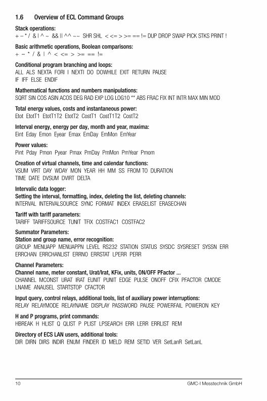
1.6 Overview of ECL Command Groups
Stack operations:+ – * / & | ^ ~ && || ^^ ~~ SHR SHL < <= > >= == != DUP DROP SWAP PICK STKS PRINT !
Basic arithmetic operations, Boolean comparisons:+ – * / & | ^ < <= > >= == !=
Conditional program branching and loops:ALL ALS NEXTA FORI I NEXTI DO DOWHILE EXIT RETURN PAUSE IF IFF ELSE ENDIF
Mathematical functions and numbers manipulations:SQRT SIN COS ASIN ACOS DEG RAD EXP LOG LOG10 ** ABS FRAC FIX INT INTR MAX MIN MOD
Total energy values, costs and instantaneous power:Etot EtotT1 EtotT1T2 EtotT2 CostT1 CostT1T2 CostT2
Interval energy, energy per day, month and year, maxima:Eint Eday Emon Eyear Emax EmDay EmMon EmYear
Power values:Pint Pday Pmon Pyear Pmax PmDay PmMon PmYear Pmom
Creation of virtual channels, time and calendar functions:VSUM VIRT DAY WDAY MON YEAR HH MM SS FROM TO DURATION TIME DATE DVSUM DVIRT DELTA
Intervalic data logger:Setting the interval, formatting, index, deleting the list, deleting channels:INTERVAL INTERVALSOURCE SYNC FORMAT INDEX ERASELIST ERASECHAN
Tariff with tariff parameters:TARIFF TARIFFSOURCE TUNIT TFIX COSTFAC1 COSTFAC2
Summator Parameters: Station and group name, error recognition:GROUP MENUAPP MENUAPPN LEVEL RS232 STATION STATUS SYSDC SYSRESET SYSSN ERRERRCHAN ERRCHANLIST ERRNO ERRSTAT LPERR PERR
Channel Parameters: Channel name, meter constant, Urat/Irat, KFix, units, ON/OFF PFactor ...CHANNEL MCONST URAT IRAT EUNIT PUNIT EDGE PULSE ONOFF CFIX PFACTOR CMODELNAME ANAUSEL STARTSTOP CFACTOR
Input query, control relays, additional tools, list of auxiliary power interruptions:RELAY RELAYMODE RELAYNAME DISPLAY PASSWORD PAUSE POWERFAIL POWERON KEY
H and P programs, print commands:HBREAK H HLIST Q QLIST P PLIST LPSEARCH ERR LERR ERRLIST REM
Directory of ECS LAN users, additional tools:DIR DIRN DIRS INDIR ENUM FINDER ID MELD REM SETID VER SetLanR SetLanL
GMC-I Messtechnik GmbH 11
LON:LONANA LONFAKTOR LONID LONCHANNEL LONMAXCHANNEL LONOFFSET LONP LONSTOPLONTYPE LONUSERS LONVER LONZW LONStatTiming LONPollDelay SetLON
Analog values:ANA ANAFACTOR ANAFIX ANAMAX ANAMAXR ANAMAXRN ANAMIN ANAMMCLR ANAMODEANAN ANAOFFSET ANAR ANARESO ANARS ANASSEL ANAUSEL
Variables:A ALIST B BLIST
Time commands:TIME DATE TM TMD HTD LASTUPD FROM TO DURATION SUWI DAYBEG MONBEG
Other:ENUM DELIMITER CHAIN DEVKEY DISPLAY FINDER LOGIN LOGOUT MELD PASSWORD KEY TX1TX2 VER WHOAMI
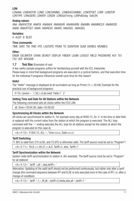
1.7 Tool Box (Examples of use)A few useful sample programs suffice for familiarizing yourself with the ECL interpreter.Please keep in mind that background programs are executed in a cyclical fashion, and that execution time for the individual H programs influences overall cycle time for this reason!
Hello!The “Hello!” message is displayed at all summators as long as Pmom (1) > 30 kW. Example for the practical use of background programs:
Setting Time and Date for All Stations within the NetworkThe following command sets all clocks within the ECS LAN:
Synchronizing All Clocks within the NetworkAll clocks are synchronized to station A:, for example every day at 0h00:15. An 'x' in the time or date field is replaced with the current value from the station at which the program is executed. The ALL loop command with the '–' ending executes the ALL loop for all stations except for the station at which the program is executed (in this case A).
Tariff SwitchingT1 (NT) is valid from 21h to 6h, and T2 (HT) is otherwise valid. The tariff source must be set to “Program”!
Tariff Synchronization within the NetworkSystem-wide tariff synchronization to station A: (for example). The tariff source must be set to “Program” for all stations!
Alternative: Updating of the valid tariff should not be performed continuously, but rather only after a tariff change (the command sequence between IFF and ELSE is only executed once in the case of IFF, i.e. after a change of condition):
H 10=’pmom – 1.30,>,if,all,meld “Hello !“ 2’
all, time=12h34.56; date=16.08.93
<A> H 10= ’if 0h0.15, ALL –, Time=x:x:x, Date=x.x.x’
<A> H 11= ’hh,6,>=,hh,21,<,&,if, Tariff=2, else, Tariff=1’
<A> H 12= ’ tariff –,all –,dup,tariff=. ’
<A> H 12= ’ tariff –,1,–,iff,all –,tariff=2,nexta,else,all –,tariff=1 ’
12 GMC-I Messtechnik GmbH
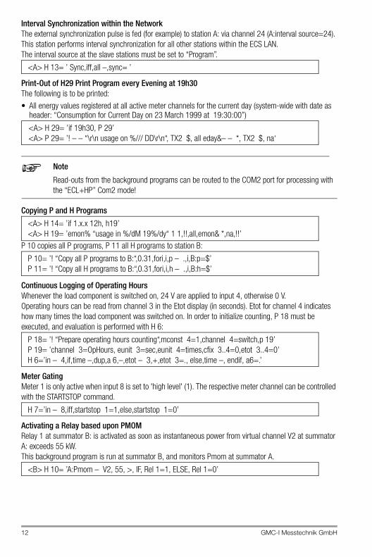
Interval Synchronization within the NetworkThe external synchronization pulse is fed (for example) to station A: via channel 24 (A:interval source=24). This station performs interval synchronization for all other stations within the ECS LAN.The interval source at the slave stations must be set to “Program”.
Print-Out of H29 Print Program every Evening at 19h30The following is to be printed:• All energy values registered at all active meter channels for the current day (system-wide with date as
header: “Consumption for Current Day on 23 March 1999 at 19:30:00”)
Note
Read-outs from the background programs can be routed to the COM2 port for processing with the “ECL+HP” Com2 mode!
Copying P and H Programs
P 10 copies all P programs, P 11 all H programs to station B:
Continuous Logging of Operating HoursWhenever the load component is switched on, 24 V are applied to input 4, otherwise 0 V.Operating hours can be read from channel 3 in the Etot display (in seconds). Etot for channel 4 indicates how many times the load component was switched on. In order to initialize counting, P 18 must be executed, and evaluation is performed with H 6:
Meter GatingMeter 1 is only active when input 8 is set to 'high level' (1). The respective meter channel can be controlled with the STARTSTOP command.
Activating a Relay based upon PMOMRelay 1 at summator B: is activated as soon as instantaneous power from virtual channel V2 at summator A: exceeds 55 kW.This background program is run at summator B, and monitors Pmom at summator A.
<A> H 13= ’ Sync,iff,all –,sync= ’
<A> H 29= ’if 19h30, P 29’<A> P 29= ’! – – “\r\n usage on %/// DD\r\n“, TX2 $, all eday&– – *, TX2 $, na‘
<A> H 14= ’if 1.x.x 12h, h19’<A> H 19= ’emon% “usage in %/dM 19%/dy“ 1 1,!!,all,emon& *,na,!!’
P 10= ’! “Copy all P programs to B:“,0.31,fori,i,p – .,i,B:p=$’P 11= ’! “Copy all H programs to B:“,0.31,fori,i,h – .,i,B:h=$’
P 18= ’! “Prepare operating hours counting“,mconst 4=1,channel 4=switch,p 19’P 19= ’channel 3=OpHours, eunit 3=sec,eunit 4=times,cfix 3..4=0,etot 3..4=0’H 6=’in – 4,if,time –,dup,a 6,–,etot – 3,+,etot 3=., else,time –, endif, a6=.’
H 7=’in – 8,iff,startstop 1=1,else,startstop 1=0’
<B> H 10= ’A:Pmom – V2, 55, >, IF, Rel 1=1, ELSE, Rel 1=0’
GMC-I Messtechnik GmbH 13
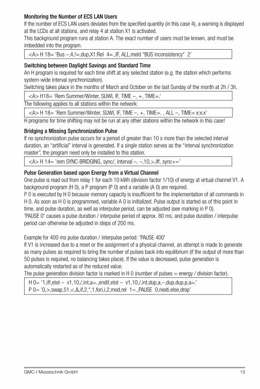
Monitoring the Number of ECS LAN UsersIf the number of ECS LAN users deviates from the specified quantity (in this case 4), a warning is displayed at the LCDs at all stations, and relay 4 at station X1 is activated.This background program runs at station A. The exact number of users must be known, and must be imbedded into the program.
Switching between Daylight Savings and Standard TimeAn H program is required for each time shift at any selected station (e.g. the station which performs system-wide interval synchronization).Switching takes place in the months of March and October on the last Sunday of the month at 2h / 3h.
The following applies to all stations within the network:
H programs for time shifting may not be run at any other stations within the network in this case!
Bridging a Missing Synchronization PulseIf no synchronization pulse occurs for a period of greater than 10 s more than the selected interval duration, an “artificial” interval is generated. If a single station serves as the “interval synchronization master”, the program need only be installed to this station.
Pulse Generation based upon Energy from a Virtual ChannelOne pulse is read out from relay 1 for each 10 kWh (division factor 1/10) of energy at virtual channel V1. A background program (H 0), a P program (P 0) and a variable (A 0) are required.P 0 is executed by H 0 because memory capacity is insufficient for the implementation of all commands in H 0. As soon as H 0 is programmed, variable A 0 is initialized. Pulse output is started as of this point in time, and pulse duration, as well as interpulse period, can be adjusted (see marking in P 0).'PAUSE 0' causes a pulse duration / interpulse period of approx. 80 ms, and pulse duration / interpulse period can otherwise be adjusted in steps of 200 ms.
Example for 400 ms pulse duration / interpulse period: 'PAUSE 400'If V1 is increased due to a reset or the assignment of a physical channel, an attempt is made to generate as many pulses as required to bring the number of pulses back into equilibrium (if the output of more than 50 pulses is required, no balancing takes place). If the value is decreased, pulse generation is automatically restarted as of the reduced value.The pulse generation division factor is marked in H 0 (number of pulses = energy / division factor).
<A> H 18= ’Bus –,4,!=,dup,X1:Rel 4=.,IF, ALL,meld “BUS inconsistency“ 2’
<A> H18= ‘Rem Summer/Winter, SUWI, IF, TIME –, +, TIME=.‘
<A> H 18= ’Rem Summer/Winter, SUWI, IF, TIME –, +, TIME=. , ALL –, TIME= x:x:x’
<A> H 14= ’rem SYNC-BRIDGING, sync/, interval –, –,10,>,iff, sync+=’
H 0= ’1,iff,etot – v1,10,/,int,a=.,endif,etot – v1,10,/,int,dup,a,–,dup,dup,p,a=.’P 0= ’0,>,swap,51,<,&,if,2,*,1,fori,i,2,mod,rel 1=.,PAUSE 0,nexti,else,drop’
14 GMC-I Messtechnik GmbH
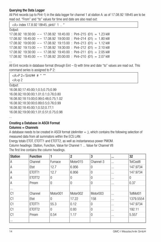
Querying the Data LoggerAll Pint records (up to Pint-1) in the data logger for channel 1 at station A: as of 17.08.92 18h45 are to be read out. “From” and “to” values for time and date are also read out:
Output:17.08.92 18:30:00 – – 17.08.92 18:45:00 : Pint–215 (01) = 1.23 kW17.08.92 18:45:00 – – 17.08.92 19:00:00 : Pint–214 (01) = 1.80 kW17.08.92 19:00:00 – – 17.08.92 19:15:00 : Pint–213 (01) = 1.12 kW17.08.92 19:15:00 – – 17.08.92 19:30:00 : Pint–212 (01) = 2.10 kW17.08.92 19:30:00 – – 17.08.92 19:45:00 : Pint–211 (01) = 2.05 kW17.08.92 19:45:00 – – 17.08.92 20:00:00 : Pint–210 (01) = 2.07 kW...All Eint records in database format (through Eint – 0) with time and date “to” values are read out. This command series is assigned to P 2:
Output:16.08.92;17:45:00;1;0.5;0.75;0.9916.08.92;18:00:00;1.01;0.1;0.76;0.8016.08.92;18:15:00;0.99;0.48;0.75;1.0216.08.92;18:30:00;0.89;0.5;0.76;0.9916.08.92;18:45:00;1;0.52;0.77;116.08.92;19:00:00;1.01;0.51;0.75;0.98...
Creating a Database in ASCII FormatColumns = ChannelsA database needs to be created in ASCII format (delimiter = ;), which contains the following selection of measured data from all summators within the ECS LAN:Energy totals ETOT, ETOTT1 and ETOTT2, as well as instantaneous power PMOM.Column headings: Station, Function, Value for Channel 1 ... Value for Channel V8The first line contains the column headings.
Station Function 1 2 3 ... 32A Channel Furnace Motor015 Channel-3 ... TotCost8A Etot 12.7 6.956 0 ... 147.9734A ETOTT1 12.7 6.956 0 ... 147.9734A ETOTT2 0 0 0 ... 0A Pmom 0 0 0 ... 0.37...C1 Channel Motor001 Motor002 Motor003 ... TotMot01C1 Etot 0 17.22 158 ... 1379.5554C1 ETOTT1 55.3 0.12 0 ... 147.9734C1 ETOTT2 0 0.93 0 ... 192.11C1 Pmom 0.54 1.17 0 ... 5.557...
<A> index 17.8.92 18h45, pint// 1 . *
<A>P 2=’Eint/## # * **<A>p 2
GMC-I Messtechnik GmbH 15
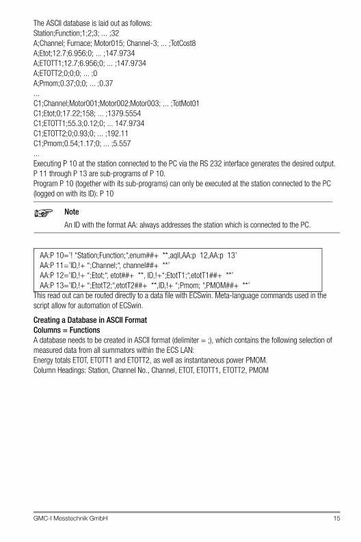
The ASCII database is laid out as follows:Station;Function;1;2;3; ... ;32A;Channel; Furnace; Motor015; Channel-3; ... ;TotCost8A;Etot;12.7;6.956;0; ... ;147.9734A;ETOTT1;12.7;6.956;0; ... ;147.9734A;ETOTT2;0;0;0; ... ;0A;Pmom;0.37;0;0; ... ;0.37...C1;Channel;Motor001;Motor002;Motor003; ... ;TotMot01C1;Etot;0;17.22;158; ... ;1379.5554C1;ETOTT1;55.3;0.12;0; ... 147.9734C1;ETOTT2;0;0.93;0; ... ;192.11C1;Pmom;0.54;1.17;0; ... ;5.557...Executing P 10 at the station connected to the PC via the RS 232 interface generates the desired output. P 11 through P 13 are sub-programs of P 10.Program P 10 (together with its sub-programs) can only be executed at the station connected to the PC (logged on with its ID): P 10
Note
An ID with the format AA: always addresses the station which is connected to the PC.
This read out can be routed directly to a data file with ECSwin. Meta-language commands used in the script allow for automation of ECSwin.
Creating a Database in ASCII FormatColumns = FunctionsA database needs to be created in ASCII format (delimiter = ;), which contains the following selection of measured data from all summators within the ECS LAN:Energy totals ETOT, ETOTT1 and ETOTT2, as well as instantaneous power PMOM.Column Headings: Station, Channel No., Channel, ETOT, ETOTT1, ETOTT2, PMOM
AA:P 10=’! “Station;Function;“,enum##+ **,aqll,AA:p 12,AA:p 13’AA:P 11=’ID,!+ “;Channel;“, channel##+ **’AA:P 12=’ID,!+ “;Etot;“, etot##+ **, ID,!+“;EtotT1;“,etotT1##+ **’AA:P 13=’ID,!+ “;EtotT2;“,etotT2##+ **,ID,!+ “;Pmom; “,PMOM##+ **’
16 GMC-I Messtechnik GmbH
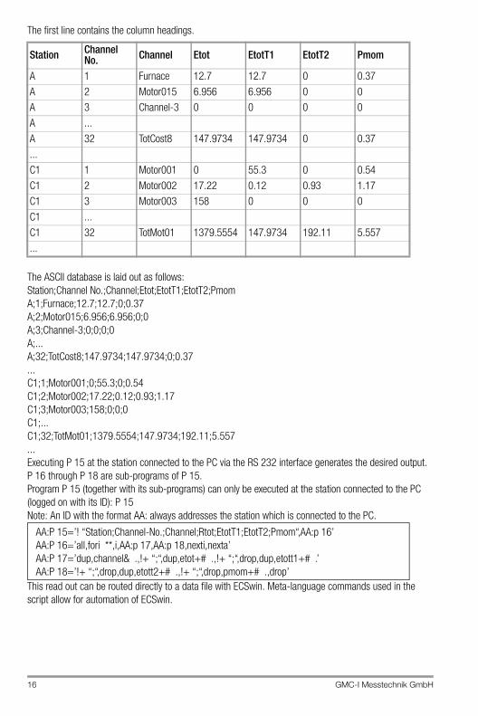
The first line contains the column headings.
The ASCII database is laid out as follows:Station;Channel No.;Channel;Etot;EtotT1;EtotT2;PmomA;1;Furnace;12.7;12.7;0;0.37A;2;Motor015;6.956;6.956;0;0A;3;Channel-3;0;0;0;0A;...A;32;TotCost8;147.9734;147.9734;0;0.37...C1;1;Motor001;0;55.3;0;0.54C1;2;Motor002;17.22;0.12;0.93;1.17C1;3;Motor003;158;0;0;0C1;...C1;32;TotMot01;1379.5554;147.9734;192.11;5.557... Executing P 15 at the station connected to the PC via the RS 232 interface generates the desired output. P 16 through P 18 are sub-programs of P 15.Program P 15 (together with its sub-programs) can only be executed at the station connected to the PC (logged on with its ID): P 15Note: An ID with the format AA: always addresses the station which is connected to the PC.
This read out can be routed directly to a data file with ECSwin. Meta-language commands used in the script allow for automation of ECSwin.
Station Channel No. Channel Etot EtotT1 EtotT2 Pmom
A 1 Furnace 12.7 12.7 0 0.37A 2 Motor015 6.956 6.956 0 0A 3 Channel-3 0 0 0 0A ...A 32 TotCost8 147.9734 147.9734 0 0.37...C1 1 Motor001 0 55.3 0 0.54C1 2 Motor002 17.22 0.12 0.93 1.17C1 3 Motor003 158 0 0 0C1 ...C1 32 TotMot01 1379.5554 147.9734 192.11 5.557...
AA:P 15=’! “Station;Channel-No.;Channel;Rtot;EtotT1;EtotT2;Pmom“,AA:p 16’AA:P 16=’all,fori **,i,AA:p 17,AA:p 18,nexti,nexta’AA:P 17=’dup,channel& .,!+ “;“,dup,etot+# .,!+ “;“,drop,dup,etott1+# .’AA:P 18=’!+ “;“,drop,dup,etott2+# .,!+ “;“,drop,pmom+# .,drop’
GMC-I Messtechnik GmbH 17
2 ECL Command List
2.1 General Information
Online Command List
GeneralInformation
General Information Concerning Use of ECL Interpreter Commands:
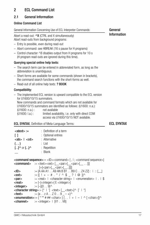
Abort a read-out: ^X (CTRL and X simultaneously)Abort read-outs from background programs:– Entry is possible, even during read-out– Abort command: see HBREAK (16 s pause for H programs)– Control character ^B disables output from H programs for 10 s
(H program read-outs are ignored during this time).
Querying special online help texts:– The search term can be entered in abbreviated form, as long as the
abbreviation is unambiguous.– Short-forms are available for some commands (shown in brackets),
the command search functions with the short-forms as well.– Read-out of all online help texts: ? BOOK
Compatibility:– The implemented ECL version is upward compatible to the ECL version
for U1600/10/15 summators.New commands and command formats which are not available for U1600/10/15 summators are identified as follows: (U1600: n.a.): (U1600: n.a.) : not available(U1600: l.a.) : limited availability, i.e. only with direct COM
access via U1600/10/15 NOT available.
ECL SYNTAXECL SYNTAX, Definition of Meta-Language Terms:
<command sequence>:= <ID><command> [ , | ; <command sequence>]<command> := <text><ext> [__<par>[__<par>[__ . . ]]]
[=[<par>[__<par>[__..]]]]<ID> := {A AA A1 . . A9 AN B B1 . . B9 C . . Z4 ZZ} : | :: [__]<ext> := [{ ! + – # . * / ^ $ _ ? | @ }]^<par> := <real> | <character string> | <enumeration> | . | $<real> := [–]<integer>[ E <integer>]<integer> := [–]{0 . . 9}^<character string>:= [“ | ’] <text> [__<text>]^ [’ | “]<text> := {a . . z A . . Z 0 . . 9 _ – +}^<enumeration>:= { * ** # ## <chan> } [ . . | + | – | ^ [ <chan>]]^<channel> := <integer> | {V1 . . V8}
<abcd> := : Definition of a term[ ] : Optional entries<ab> | <cd> : Alternative{ . . } : List[. .]^ or {. .}^ : Repetition__ : Blank
18 GMC-I Messtechnik GmbH
Extensions Extensions
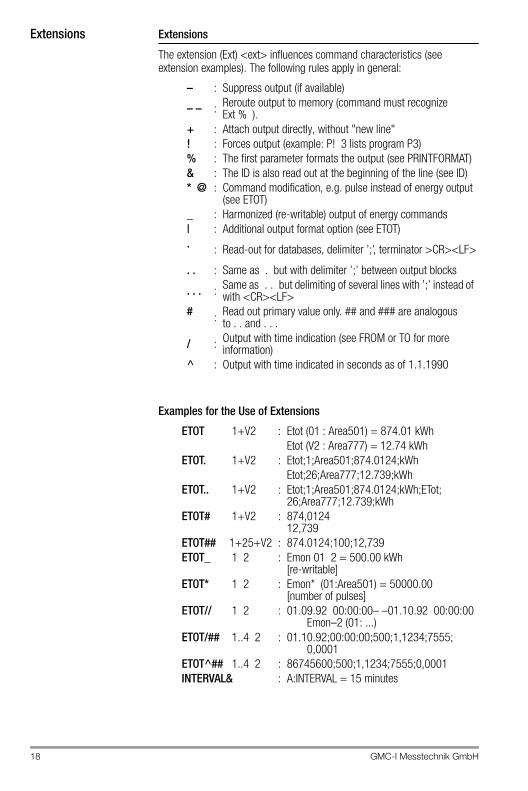
The extension (Ext) <ext> influences command characteristics (see extension examples). The following rules apply in general:
Examples for the Use of Extensions
– : Suppress output (if available)
– – : Reroute output to memory (command must recognize Ext % ).
+ : Attach output directly, without "new line"! : Forces output (example: P! 3 lists program P3)% : The first parameter formats the output (see PRINTFORMAT)& : The ID is also read out at the beginning of the line (see ID)* @ : Command modification, e.g. pulse instead of energy output
(see ETOT)_ : Harmonized (re-writable) output of energy commands| : Additional output format option (see ETOT). : Read-out for databases, delimiter ’;’, terminator >CR><LF>
. . : Same as . but with delimiter ’;’ between output blocks
. . . : Same as . . but delimiting of several lines with ’;’ instead of with <CR><LF>
# : Read out primary value only. ## and ### are analogous to . . and . . .
/ : Output with time indication (see FROM or TO for more information)
^ : Output with time indicated in seconds as of 1.1.1990
ETOT 1+V2 : Etot (01 : Area501) = 874.01 kWhEtot (V2 : Area777) = 12.74 kWh
ETOT. 1+V2 : Etot;1;Area501;874.0124;kWhEtot;26;Area777;12.739;kWh
ETOT.. 1+V2 : Etot;1;Area501;874.0124;kWh;ETot;26;Area777;12.739;kWh
ETOT# 1+V2 : 874,012412,739
ETOT## 1+25+V2 : 874.0124;100;12,739ETOT_ 1 2 : Emon 01 2 = 500.00 kWh
[re-writable]ETOT* 1 2 : Emon* (01:Area501) = 50000.00
[number of pulses]ETOT// 1 2 : 01.09.92 00:00:00– –01.10.92 00:00:00
Emon–2 (01: ...)ETOT/## 1..4 2 : 01.10.92;00:00:00;500;1,1234;7555;
0,0001ETOT^## 1..4 2 : 86745600;500;1,1234;7555;0,0001INTERVAL& : A:INTERVAL = 15 minutes
GMC-I Messtechnik GmbH 19
Command ParametersCommand Parameters
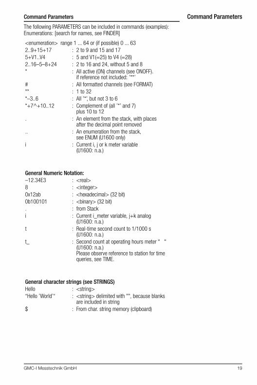
The following PARAMETERS can be included in commands (examples):Enumerations: [search for names, see FINDER]
<enumeration> range 1 ... 64 or (if possible) 0 ... 632..9+15+17 : 2 to 9 and 15 and 175+V1..V4 : 5 and V1(=25) to V4 (=28)2..16–5–8+24 : 2 to 16 and 24, without 5 and 8* : All active (ON) channels (see ONOFF).
if reference not included: ’**’# : All formatted channels (see FORMAT)** : 1 to 32*–3..6 : All ’*’, but not 3 to 6*+7^+10..12 : Complement of (all ’*’ and 7)
plus 10 to 12. : An element from the stack, with places
after the decimal point removed.. : An enumeration from the stack,
see ENUM (U1600 only)i : Current i, j or k meter variable
(U1600: n.a.)
General Numeric Notation:–12.34E3 : <real>8 : <integer>0x12ab : <hexadecimal> (32 bit)0b100101 : <binary> (32 bit). : from Stacki : Current i_meter variable, j+k analog
(U1600: n.a.)t : Real-time second count to 1/1000 s
(U1600: n.a.)t_ : Second count at operating hours meter " "
(U1600: n.a.)Please observe reference to station for time queries, see TIME.
General character strings (see STRINGS)Hello : <string>“Hello ’World’“ : <string> delimited with "", because blanks
are included in string$ : From char. string memory (clipboard)
20 GMC-I Messtechnik GmbH
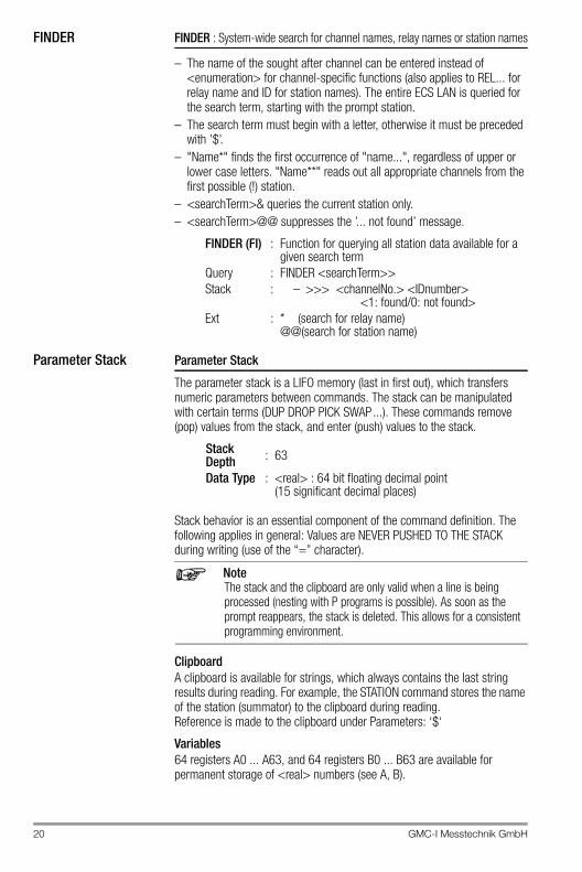
FINDER FINDER : System-wide search for channel names, relay names or station names
– The name of the sought after channel can be entered instead of <enumeration> for channel-specific functions (also applies to REL... for relay name and ID for station names). The entire ECS LAN is queried for the search term, starting with the prompt station.
– The search term must begin with a letter, otherwise it must be preceded with ’$’.
– "Name*" finds the first occurrence of "name...", regardless of upper or lower case letters. "Name**" reads out all appropriate channels from the first possible (!) station.
– <searchTerm>& queries the current station only.– <searchTerm>@@ suppresses the ’... not found’ message.
Parameter Stack Parameter Stack
The parameter stack is a LIFO memory (last in first out), which transfers numeric parameters between commands. The stack can be manipulated with certain terms (DUP DROP PICK SWAP...). These commands remove (pop) values from the stack, and enter (push) values to the stack.
Stack behavior is an essential component of the command definition. The following applies in general: Values are NEVER PUSHED TO THE STACK during writing (use of the “=” character).
NoteThe stack and the clipboard are only valid when a line is being processed (nesting with P programs is possible). As soon as the prompt reappears, the stack is deleted. This allows for a consistent programming environment.
ClipboardA clipboard is available for strings, which always contains the last string results during reading. For example, the STATION command stores the name of the station (summator) to the clipboard during reading.Reference is made to the clipboard under Parameters: ‘$‘
Variables64 registers A0 ... A63, and 64 registers B0 ... B63 are available for permanent storage of <real> numbers (see A, B).
FINDER (FI) : Function for querying all station data available for a given search term
Query : FINDER <searchTerm>>Stack : – >>> <channelNo.> <IDnumber>
<1: found/0: not found>Ext : * (search for relay name)
@@(search for station name)
Stack Depth : 63
Data Type : <real> : 64 bit floating decimal point(15 significant decimal places)
GMC-I Messtechnik GmbH 21
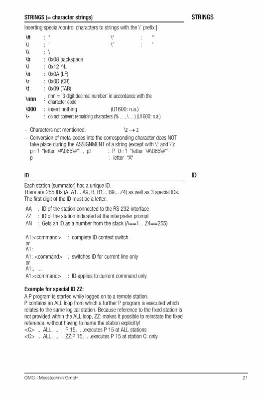
STRINGSSTRINGS (= character strings)
Inserting special/control characters to strings with the \’ prefix:]
– Characters not mentioned: \z z– Conversion of meta-codes into the corresponding character does NOT
take place during the ASSIGNMENT of a string (except with \“ and \’): p=’! “letter \#\065\#“’ , p! : P 0=’! “letter \#\065\#“’p : letter “A“
IDID
Each station (summator) has a unique ID.There are 255 IDs (A, A1... A9, B, B1... B9... Z4) as well as 3 special IDs. The first digit of the ID must be a letter.
Example for special ID ZZ:A P program is started while logged on to a remote station. P contains an ALL loop from which a further P program is executed which relates to the same logical station. Because reference to the fixed station is not provided within the ALL loop, ZZ: makes it possible to reinstate the fixed reference, without having to name the station explicitly!<C> .. ALL, .. , P 15, ...executes P 15 at ALL stations<C> .. ALL, .. , ZZ:P 15, ...executes P 15 at station C: only
\# : “ \“ : “\| : ’ \’ : ’\\ : \\b : 0x08 backspace\l : 0x12 ^L\n : 0x0A (LF)\r : 0x0D (CR)\t : 0x09 (TAB)
\nnn : nnn = ’3 digit decimal number’ in accordance with the character code
\000 : insert nothing (U1600: n.a.)\- : do not convert remaining characters (% ... , \ ... ) (U1600: n.a.)
AA : ID of the station connected to the RS 232 interfaceZZ : ID of the station indicated at the interpreter promptAN : Gets an ID as a number from the stack (A==1... Z4==255)
A1:<command>orA1:
: complete ID context switch
A1: <command>orA1:, ...
: switches ID for current line only
A1:<command> : ID applies to current command only
22 GMC-I Messtechnik GmbH
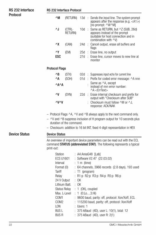
RS 232 InterfaceProtocol
RS 232 Interface Protocol
Protocol Flags
– Protocol Flags ^A, ^V and ^B always apply to the next command only.– ^V and ^B suppress inclusion of H program output for 10 seconds plus
duration of the command.– Checksum: addition to 16 bit INT, fixed 4-digit representation in HEX
Device Status Device Status
An overview of important device parameters can be read out with the ECL command STATUS (abbreviated STAT). The following represents a typical print-out:
^M (RETURN) 13d : Sends the input line. The system prompt appears after the response (e.g. <A1>) [no prompt: ^W^M]
^J (CTRL-RETURN)
10d : Same as RETURN, but ^Z (SUB, 26d) appears instead of the prompt(suitable for host connection and in combination with ^V)
^X (CAN) 24d : Cancel output, erase all buffers and flags
^Y (EM) 25d : Erase line, no outputESC 27d : Erase line, cursor moves to new line at
monitor
^B (STX) 02d : Suppresses input echo for current line^A (SOH) 01d : Prefix for coded error message: ^A nnn
^A^A : Same as ^A, except instead of nnn error number: ^A <ErrText>
^V (SYN) 22d : Erase internal checksum and prefix for output with "Checksum after SUB"
^V^V : Checksum must follow ^M or ^J, response: ACK/NAK
Station : A4:AreaG48 [Lab]ECS U1601 : Software V2.47 (22.03.02)Interval : 1 m (time)Format (0) : 64 channels, 3966 records (2.8 days), 193 usedTariff : T1 (program)Relay : R1:p R2:p R3:p R4:p R5:p R6:p24 V Output : OKLithium Batt. : OKStatus Relay : 1 (OK), coupledMax. L-Level : 1 (0:Lo....3:Hi)COM1 : 9600 baud, parity: off, protocol: Xon/Xoff, ECLCOM2 : 115200 baud, parity: off, protocol: Xon/XoffLON : Users: 1BUS L : 375 kBaud (4D), user L: 10(1), total: 12BUS R : 375 kBaud (4D), user R: 2(1)
GMC-I Messtechnik GmbH 23
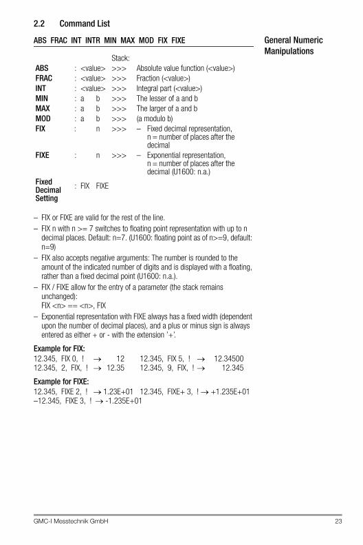
2.2 Command List
General Numeric Manipulations
ABS FRAC INT INTR MIN MAX MOD FIX FIXE
– FIX or FIXE are valid for the rest of the line.– FIX n with n >= 7 switches to floating point representation with up to n
decimal places. Default: n=7. (U1600: floating point as of n>=9, default: n=9)
– FIX also accepts negative arguments: The number is rounded to the amount of the indicated number of digits and is displayed with a floating, rather than a fixed decimal point (U1600: n.a.).
– FIX / FIXE allow for the entry of a parameter (the stack remains unchanged):FIX <n> == <n>, FIX
– Exponential representation with FIXE always has a fixed width (dependent upon the number of decimal places), and a plus or minus sign is always entered as either + or - with the extension ’+’.
Example for FIX:12.345, FIX 0, ! 12 12.345, FIX 5, ! 12.3450012.345, 2, FIX, ! 12.35 12.345, 9, FIX, ! 12.345
Example for FIXE:12.345, FIXE 2, ! 1.23E+01 12.345, FIXE+ 3, ! +1.235E+01–12.345, FIXE 3, ! -1.235E+01
Stack:ABS : <value> >>> Absolute value function (<value>)FRAC : <value> >>> Fraction (<value>)INT : <value> >>> Integral part (<value>)MIN : a b >>> The lesser of a and bMAX : a b >>> The larger of a and bMOD : a b >>> (a modulo b)FIX : n >>> – Fixed decimal representation,
n = number of places after the decimal
FIXE : n >>> – Exponential representation, n = number of places after the decimal (U1600: n.a.)
Fixed Decimal Setting
: FIX FIXE
24 GMC-I Messtechnik GmbH
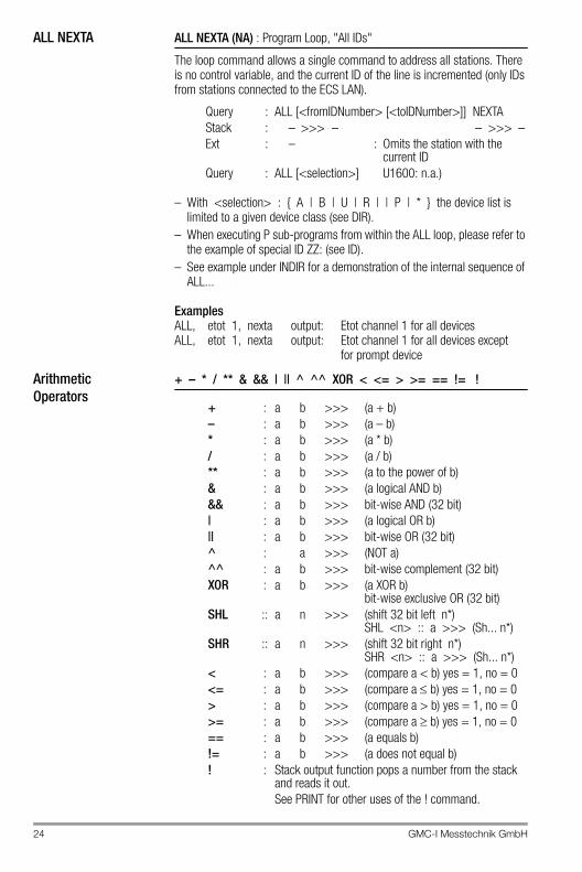
ALL NEXTA ALL NEXTA (NA) : Program Loop, "All IDs"
The loop command allows a single command to address all stations. There is no control variable, and the current ID of the line is incremented (only IDs from stations connected to the ECS LAN).
– With <selection> : { A | B | U | R | | P | * } the device list is limited to a given device class (see DIR).
– When executing P sub-programs from within the ALL loop, please refer to the example of special ID ZZ: (see ID).
– See example under INDIR for a demonstration of the internal sequence of ALL...
ExamplesALL, etot 1, nexta output: Etot channel 1 for all devicesALL, etot 1, nexta output: Etot channel 1 for all devices except
for prompt device
ArithmeticOperators
+ – * / ** & && | || ^ ^^ XOR < <= > >= == != !
Query : ALL [<fromIDNumber> [<toIDNumber>]] NEXTAStack : – >>> – – >>> –Ext : – : Omits the station with the
current IDQuery : ALL [<selection>] U1600: n.a.)
+ : a b >>> (a + b)– : a b >>> (a – b)* : a b >>> (a * b)/ : a b >>> (a / b)** : a b >>> (a to the power of b)& : a b >>> (a logical AND b)&& : a b >>> bit-wise AND (32 bit)| : a b >>> (a logical OR b)|| : a b >>> bit-wise OR (32 bit)^ : a >>> (NOT a)^^ : a b >>> bit-wise complement (32 bit)XOR : a b >>> (a XOR b)
bit-wise exclusive OR (32 bit)SHL :: a n >>> (shift 32 bit left n*)
SHL <n> :: a >>> (Sh... n*)SHR :: a n >>> (shift 32 bit right n*)
SHR <n> :: a >>> (Sh... n*)< : a b >>> (compare a < b) yes = 1, no = 0<= : a b >>> (compare a b) yes = 1, no = 0> : a b >>> (compare a > b) yes = 1, no = 0>= : a b >>> (compare a b) yes = 1, no = 0== : a b >>> (a equals b)!= : a b >>> (a does not equal b)! : Stack output function pops a number from the stack
and reads it out.See PRINT for other uses of the ! command.
GMC-I Messtechnik GmbH 25
Bit Shifts and Binary-BCD Transformations
NoteCommands identified with "::" have only limited availability with U1600/10/15 (U1600: l.a.).
The following applies to logical comparisons: FALSE: equal to 0.0, TRUE: not equal to 0.0
A/B RegistersA0 . . A63 : Registers A0 ... A63 for <real> numbers (U1600: A0 ... A9) B0 . . B63 : Registers B0 ... B63 for <real> numbers (U1600: n.a.).
– A without <enumeration> == A0– A1 . . A19 correspond to A 1 . . A 19, A5! == A! 5– Increment (+1) : A++ <enumeration>– Decrement (–1) : A–– <enumeration>– Add <value> to register:
A++ <enumeration> = <value>– Subtract <value> from register:
A–– <enumeration> = <value>– <newValue> == {t|z} assigns the current second count
(with 1/100 s).ALIST or ALIST <enumeration> :Lists A registers(corresponds to A! *)
SHL :: a n >>> (shift 32 bit left n*)SHL <n> :: a >>> (Sh... n*)SHR :: a n >>> (shift 32 bit right n*)SHR <n> :: a >>> (Sh... n*)
BIN2BCD :: bin >>> bcd Binary BCD; example: 1234 >>> 0x1234
BCD2BIN :: bcd >>> bin BCD binary; example: 0x1234 >>> 1234
Query A <enumeration> [=<newValue>]
Stack : – >>> Content (Ai) Query (sum is generated for
enumeration)
value >>> – AssignmentExt : + – . # ! ++ – – %
26 GMC-I Messtechnik GmbH
Analog Processing ANA: Analog Processing
Analog Inputs– Energy is calculated from an analog power value with AnaMODE = 2.– To count pulses, select AnaMODE=3. The input status can be queried
with INPUT {0|1}. The LEVEL command defines the switching threshold: 0 = 10%, 1 = 250 = 10%, 1 = 25% (default), 2 = 50%, 3 = 70% of full range. PULSEDURATION is used to evaluate the input status.
– STARTSTOP influences energy computing in AnaMODE= 2 or 3.– The input characteristic is selected with AnaMODSEL
(device hardware must also be configured accordingly).
– U1601 makes 12 inputs available at channels 1 through 12.– U1603 makes 6 inputs available at channels 1 through 6.– U1615 makes a maximum of 7 inputs available at channels 1 through 7.
Analog Outputs:– The AnaRESO command has no significance (for U1615: AnaMAX and AnaMIN also).
AnaMODE 0 deactivates the output. AnaMODE 2, 3 is not allowable.
– U1601/3 makes 2 outputs available at channels 13 + 14 (ANA 13/ANA 14).– U1615 makes a maximum of 7 outputs (unipolar only) available at
channels 1 through 7.– The output characteristic is selected with AnaMODSEL.
The following applies to U1601 (device hardware must also be configured correspondingly):
– The following applies to U1615:
– Slave pointer mean value generation (accurate to the second) is activated at the analog output with the AnaINT command (where n > 0). The output and ANA (reading) continuously read out the mean value of assigned ANA values for the last n seconds. AnaINT is available with U1601 variants manufactured as of 8 November 1999.
0 : –10 ... 0 ... +10 V1 : –20 ... 0 ... +20 mA2 : –5 ... 0 ... +5 mA3 : S04 : 4 ... 20 mA (20 mA range)
0 : –10 ... 0 ... +10 V1 : –20 ... 0 ... +20 mA4 : 4 ... 20 mA (20 mA range)
0 : 0 ... +20 mA1 : 4 ... 20 mA (20 mA range)
Query : AnaINT <channel> [= <value>] mean value generationinterval in seconds (*)
0 : Default instantaneous value1...60 : Slave pointer interval
GMC-I Messtechnik GmbH 27
Relay Outputs (U1615 only):– Only the AnaModID and AnaRelMap commands are logical.– The U1615 makes up to 7 relay outputs (normally open contact) available
at channels 1 though 7.
General– Ext ’?’ (ANA? 1 ) suppresses the “function not available” error message at
stations not equipped with analog processing.– Commands identified with (*) are not available at the U1615.
Query : ANA <channel> analog input
Query : ANA <channel> =<value> analog output
Query : AnaR <channel> [=<value>] analog I/O, raw value corresponding toAnaModSel (*)
Query : AnaN <channel> [=<value>] analog I/O,–1 ... 0 ... +1 scaled value (*)
Query : AnaRS <channel> [=<value>] analog I/O, raw value corresponding to AnaModSel, prefix range (see AnaSSEL) although not restricted.
Query : AnaMAX <channel> [=<value>] maximum (with time stamp:)ANAMAX/ <channel>)
Query : AnaMIN <channel> [=<value>] minimum (new time stamp:)ANAMIN/ <k> = <w>)
Query : AnaMAXR, AnaMINR maximum/minimum, same value range as AnaR (*)
Query : AnaMAXN, AnaMINN maximum/minimum, same value range as AnaN (*)
Query : AnaMMCLR <channel> = 0 maximum and minimum (*)
Query : AnaFACTOR <channel> [=<value>]
28 GMC-I Messtechnik GmbH
Query : AnaOFFSET <channel> [=<value>]ANA = AnaN * AnaFACTOR + AnaOFFSETAnaOFFSET = minimum scale valueAnaFACTOR = full scale value - minimum scale value
ExampleMeasured values 0 through 20 mA are to be assigned to a
temperature range of 200 to 300° C.
AnaOFFSET = 200AnaFACTOR = 300 - 200 = 100
Query : AnaUSEL <channel> [=<value>] Ana unit, <value>: 0 = none1 = EUNIT2 = PUNIT
Query : AnaFIX <channel> [=<value>] fixed point for analog value (U1600: n.a.)0 : 0. 1 : 0.0 2 : 0.00 3 : 0.000 9 : Floating decimal(floating decimal for <value> : 4 ... 9)
Query : AnaSSEL <channel> [=<value>] +/–range, <value>: 0 = +/–, 1 = +, 2 = –
Query : AnaRESO <channel> [=<value>] res. in meas. points Specification: 2000
Query : AnaModID <channel> module type (query only)
Query : AnaModSN <channel> module serial number (query only)
Query : AnaModDC <channel> module date code (query only)
Query : AnaCAL [*]<channel> <m> [=<value>] module calibration
Query : AnaModSel <chan> [=<value>] internal function: module selectionI/O option
Query : AnaRelMap<module> [=<relay>] mapping of relay modules
to relay numbers<relay>
0 : identity1 ... 7 : <module> is <assigned> to relay
GMC-I Messtechnik GmbH 29
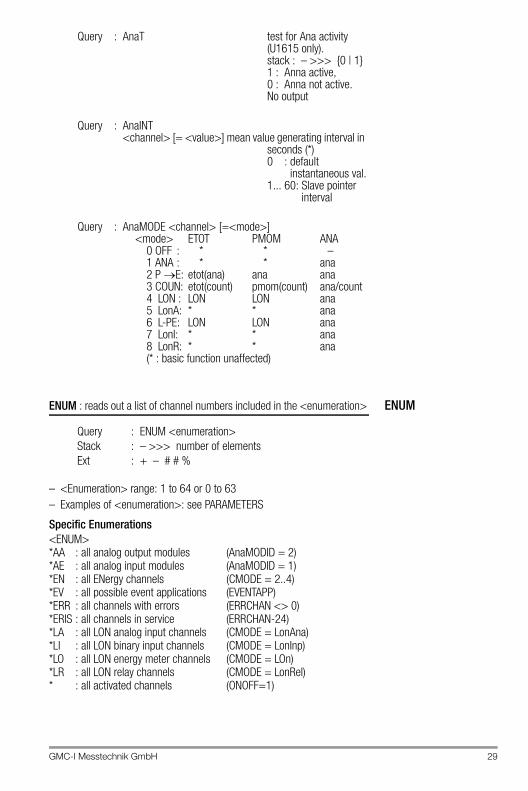
ENUMENUM : reads out a list of channel numbers included in the <enumeration>
– <Enumeration> range: 1 to 64 or 0 to 63– Examples of <enumeration>: see PARAMETERS
Specific Enumerations<ENUM>*AA : all analog output modules (AnaMODID = 2)*AE : all analog input modules (AnaMODID = 1)*EN : all ENergy channels (CMODE = 2..4)*EV : all possible event applications (EVENTAPP)*ERR : all channels with errors (ERRCHAN <> 0)*ERIS : all channels in service (ERRCHAN-24)*LA : all LON analog input channels (CMODE = LonAna)*LI : all LON binary input channels (CMODE = LonInp)*LO : all LON energy meter channels (CMODE = LOn)*LR : all LON relay channels (CMODE = LonRel)* : all activated channels (ONOFF=1)
Query : AnaT test for Ana activity (U1615 only).stack : – >>> {0 | 1}1 : Anna active, 0 : Anna not active. No output
Query : AnaINT <channel> [= <value>] mean value generating interval in
seconds (*)0 : default
instantaneous val.1... 60: Slave pointer
interval
Query : AnaMODE <channel> [=<mode>]<mode> ETOT PMOM ANA
0 OFF : * * –1 ANA : * * ana2 P E: etot(ana) ana ana3 COUN: etot(count) pmom(count) ana/count4 LON : LON LON ana5 LonA: * * ana6 L-PE: LON LON ana7 LonI: * * ana8 LonR: * * ana(* : basic function unaffected)
Query : ENUM <enumeration>Stack : – >>> number of elementsExt : + – # # %
30 GMC-I Messtechnik GmbH
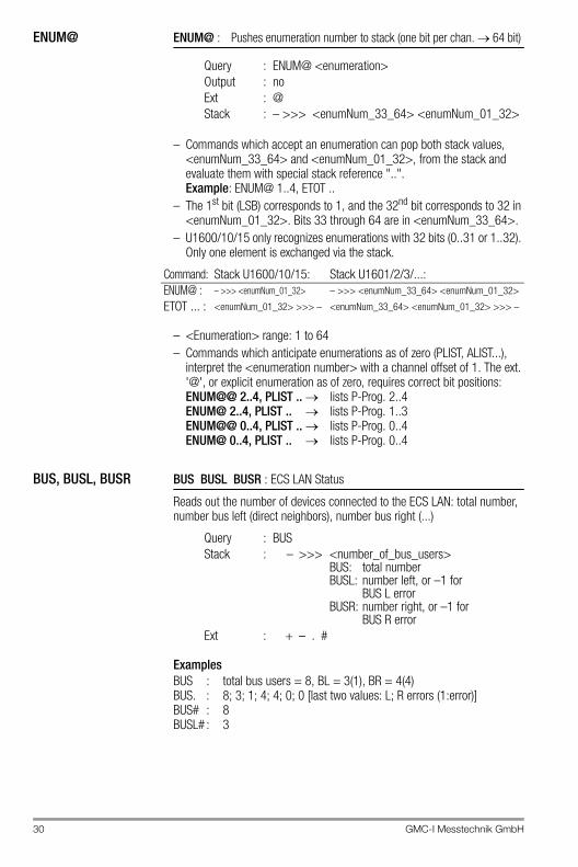
ENUM@ ENUM@ : Pushes enumeration number to stack (one bit per chan. 64 bit)
– Commands which accept an enumeration can pop both stack values, <enumNum_33_64> and <enumNum_01_32>, from the stack and evaluate them with special stack reference "..". Example: ENUM@ 1..4, ETOT ..
– The 1st bit (LSB) corresponds to 1, and the 32nd bit corresponds to 32 in <enumNum_01_32>. Bits 33 through 64 are in <enumNum_33_64>.
– U1600/10/15 only recognizes enumerations with 32 bits (0..31 or 1..32). Only one element is exchanged via the stack.
– <Enumeration> range: 1 to 64– Commands which anticipate enumerations as of zero (PLIST, ALIST...),
interpret the <enumeration number> with a channel offset of 1. The ext. '@', or explicit enumeration as of zero, requires correct bit positions:ENUM@@ 2..4, PLIST .. lists P-Prog. 2..4ENUM@ 2..4, PLIST .. lists P-Prog. 1..3ENUM@@ 0..4, PLIST .. lists P-Prog. 0..4ENUM@ 0..4, PLIST .. lists P-Prog. 0..4
BUS, BUSL, BUSR BUS BUSL BUSR : ECS LAN Status
Reads out the number of devices connected to the ECS LAN: total number, number bus left (direct neighbors), number bus right (...)
ExamplesBUS : total bus users = 8, BL = 3(1), BR = 4(4)BUS. : 8; 3; 1; 4; 4; 0; 0 [last two values: L; R errors (1:error)]BUS# : 8BUSL# : 3
Query : ENUM@ <enumeration>Output : noExt : @Stack : – >>> <enumNum_33_64> <enumNum_01_32>
Command: Stack U1600/10/15: Stack U1601/2/3/...:ENUM@ : – >>> <enumNum_01_32> – >>> <enumNum_33_64> <enumNum_01_32>
ETOT ... : <enumNum_01_32> >>> – <enumNum_33_64> <enumNum_01_32> >>> –
Query : BUSStack : – >>> <number_of_bus_users>
BUS: total numberBUSL: number left, or –1 for
BUS L errorBUSR: number right, or –1 for
BUS R errorExt : + – . #
GMC-I Messtechnik GmbH 31
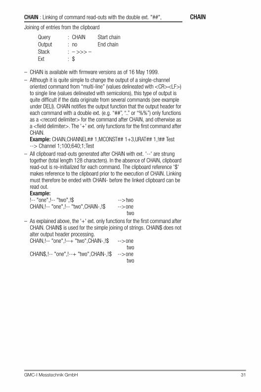
CHAINCHAIN : Linking of command read-outs with the double ext. "##",
Joining of entries from the clipboard
– CHAIN is available with firmware versions as of 16 May 1999.– Although it is quite simple to change the output of a single-channel
oriented command from “multi-line” (values delineated with <CR><LF>) to single line (values delineated with semicolons), this type of output is quite difficult if the data originate from several commands (see example under DELI). CHAIN notifies the output function that the output header for each command with a double ext. (e.g. “##”, “..” or “%%”) only functions as a <record delimiter> for the command after CHAIN, and otherwise as a <field delimiter>. The '+' ext. only functions for the first command after CHAIN. Example: CHAIN,CHANNEL## 1,MCONST## 1+3,URAT## 1,!## Test --> Channel 1;100;640;1;Test
– All clipboard read-outs generated after CHAIN with ext. '--' are strung together (total length 128 characters). In the absence of CHAIN, clipboard read-out is re-initialized for each command. The clipboard reference '$' makes reference to the clipboard prior to the execution of CHAIN. Linking must therefore be ended with CHAIN- before the linked clipboard can be read out. Example: !-- "one",!-- "two",!$ --> two CHAIN,!-- "one",!-- "two",CHAIN-,!$ --> one
two– As explained above, the '+' ext. only functions for the first command after
CHAIN. CHAIN$ is used for the simple joining of strings. CHAIN$ does not alter output header processing. CHAIN,!-- "one",!--+ "two",CHAIN-,!$ --> one
twoCHAIN$,!-- "one",!--+ "two",CHAIN-,!$ --> one
two
Query : CHAIN Start chainOutput : no End chainStack : – >>> –Ext : $
32 GMC-I Messtechnik GmbH
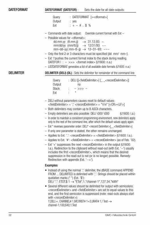
DATEFORMAT DATEFORMAT (DATEFOR) : Sets the date for all date outputs:
– Commands with date output: Override current format with Ext ~– Possible values for <dformat>:
dd.mm.yy (tt.mm.jj) 31.12.93: ~mm/dd/yy (mm/tt/jj) 12/31/93: ~~mm–dd–yy ( mm–tt–jj) 12–31–93: ~~~
– Only the first 2 or 3 characters must be specified {dd mm/ mm–}.– Ext ‘|‘pushes the current format index to the stack during reading.
DATEFOR | : – >>> <format index> (U1600: n.a.)– LISTDATEFORMAT generates a list of all available date formats (U1600: n.a.)
DELIMITER DELIMITER (DELI) (DL) : Sets the delimiter for remainder of the command line
– DELI without parameters causes reset to default values: <fieldDelimiter> = ';' <recordDelimiter> = "\r\n" [<CR><LF>]
– Both delimiters may contain up to 8 ASCII characters.– Empty delimiters are also possible: DELI \000 \000 (U1600: l.a.)– In order to maintain a consistent programming environment, new delimiters apply
only to the rest of the command line, after which the default values apply again.– Ext * reverses parameter order: DELI* <record Delimiter>[__<fieldDelimiter>]– If only one parameter is stated, the other remains unchanged.– Applies to Ext. '.': <recordDelimiter> = <fieldDelimiter> (U1600: l.a.).– Applies to Ext. '#': <fieldDelimiter> = <recordDelimiter> (as of Feb. ’02).– Ext '+' suppresses the next <recordDelimiter> in the output (U1600:
l.a.). Redirection to the clipboard without read-out (with Ext. '--') usually includes the first <recordDelimiter>, which means that the desired suppression in the read-out is not (or is no longer) possible. Remedy: Redirection with appendix (Ext. '--+').
Examples• Instead of using the normal ';' delimiter, the dBASE command APPEND
FROM ... DELIMITED is delimited with ','. Strings should be placed within quotation marks (" ") (Ext. '$'): DELI ","; ETOT.$ 1 "ETot",1,"channel-1",127.34,"kWh"
• Several different values should be delimited for output with semicolons. <recordDelimeter> and <fieldDelimiter> are set to equal values to this end, and the first semicolon is suppressed (note: read-outs always start with <recordDelimiter>): !!,DELI.+, CHANNEL# 1,MCONST# 1+3,URAT# 1,! Test channel-1;100;640;1;Test
Query : DATEFORMAT [=<dformat>] Output : yesExt : + – # . $ %
Query : DELI [[<fieldDelimiter>] [_ _<recordDelimiter>]]Output noStack : – >>> –Ext : *
GMC-I Messtechnik GmbH 33
DELTADELTA
– STARTSTOP enables assignment (STSP == 1) or ignores it (STSP == 0).– The <value> can be weighted with an optional <factor> (U1600: n.a.).
DevKEYDevKEY : Query Device KeyEnter Enabling Code (open code)
– Protected device settings (such as passwords) can be initialized (deleted) with DevKEY. Procedure: Query the current device key: DEVKEY Please inform your device dealer of this key and request an enabling code (specifically for your key) for a certain task (e.g. delete all ECL and control panel passwords). Entering the enabling (open) code: DEVKEY = <openCode>
– Important: DEVKEY functions system-wide, and correct addressing for the DEVKEY command must be observed. As soon as the enabling code assignment has been correctly entered, both the device key and the code become INVALID! If an additional enabling code is required, a NEW key must be queried with DEVKEY and the entire process must be repeated. As long as a key remains valid, it can be queried as often as desired.
DELTA : One-time addition of an energy quantity to a channel. Corresponds to a one-time only utilization of DVIRT with a specific energy value.
Query : DELTA <enumeration> [<factor>] = <value>Stack : – >>> –Ext : |
DELTA| ... : Only positive quantities are considered.DELTA| | ... : Only negative quantities are considered.
Query : DEVKEY DEVKEY = <openCode>Function : Key query Open (see below)Output : yes no noStack : – >>> <systemKey> – >>> –
34 GMC-I Messtechnik GmbH
DIR, DIRN, DIRS DIR DIRN DIRS : Directory of All ECS LAN Users
– DIR containing ESC LAN information: see DIRS– The user list can be limited by entering a selection criterion (1600 n.a.).
DISPLAY DISPLAY (DD) : Read out display
– The cursor in the display is encoded with a preceding ’&’.– Encoding on the LED/RELAY information line:
'-' : OFF,'*' : ON,
– Ext # : output without "" quotation marks– Ext | : only shows LED line (U1600: l.a.)– Ext | | : only shows text lines (U1600: l.a.)– This command is also valid for U1602 and U1603, although they are not
equipped with a physical display.
<selection> : { A | B | U | R | P | * }DIR : ID only for all users (A:)DIRN : ID and STATION NAME of all users (A: U1601)DIRN_ : ID and STATION NAME of the selected stationsStack : – >>> –Ext : + – # . %
DIRS : Same as DIR, but with information for each ID. L = left, R = right, + = direct neighbor, * = “me”
Stack : – >>> <number_of_bus_users>Ext : + – # .
* : all stations (need not be entered)U : all U16xx stations (AB or BA also possible)A : all U1600/10/15 stationsB : U1601 stations
Query : DISPLAY [<keyboardString ...>]<keyboardString ...> : see KEY
Stack : – >>> –Ext : + – # |Output : U1600:
3 lines: 1st + 2nd LCD line + 1 line indicating status of the 8 LEDs[LAN/L LAN/R R1 R2 R3 R4 STATUS STAT24V]U1601: 17 lines: LCD lines 1 through 16 + 1 line indicating status of the 4 LEDs, and status of the 6 relays[STATUS LAN/L LAN/R LON R1 R2 R3 R4 R5 R6]
GMC-I Messtechnik GmbH 35
DUP, DROP, SWAP, PICK
DUP (DU) DROP (DR) SWAP (SW) PICK : Stack Manipulations
DVSUM, DVIRTdVSUM dVIRT : Definition function used for creating virtual channels (in a background H program) with “differential summation”.
– DVIRT can be used for all channels, but only one time per channel. DVIRT may only be executed in H programs and CANNOT be influenced with IF..THEN..ELSE.
– Partial energy / power is multiplied by the <factor>, if one is entered. Attention: The <factor> must be static, i.e. it may not be altered by the program sequence.
– Ext. '|' is only possible with DVIRT. If this ext. is used, only positive ('|'), or only negative (“||”) quantities and power values are considered. Applications example: A base channel is broken down into an import and an export channel. Limitations: This function only works correctly if exactly one summator channel is used. Use with several summator channels may result in infinite addition/subtraction of minimal differences. Only energy quantities and power values generated by DVSUM/DVIRT are restricted in combination with ext. '+', and not energy measured directly from the target channel.
– Instantaneous power, PMOM, for the created channel corresponds to the sum of instantaneous power at the base channels. If DVIRT generation is interrupted for more than 30 s, PMOM is set to zero, or to the measured
DUP : n1 n2 >>> n1 n2 n2DROP : n1 n2 n3 >>> n1 n2SWAP : n1 n2 >>> n2 n1
DUP <n> : Executes DUP n times.DROP <n> : Executes DROP n times.PICK <i> : Copies the ith stack element to the top.
’PICK 1’ == ’DUP’
dVSUM : Generates totals for enumerated channels and stores them to intermediate registers.
Query : dVSUM <enumeration> [<factor>]Stack : – >>> –
dVIRT : Assigns intermediate register differential sums to the virtual channels
Query : dVIRT <enumeration> [<factor>] =Stack : – >>> –Ext : + * |
dVIRT+ ... : Calculated energy is added to energy measured at the target channel. Measured energy has no effect without ext ‘+‘.
dVIRT* ... : The intermediate registers are normally cleared after DVIRT. However, they remain intact if ext ‘*‘ is used.
36 GMC-I Messtechnik GmbH
RMS value. Shorter interruptions DO NOT result in data loss for energy quantities!
– The sums at the virtual channel are entirely independent of the base channels (indefinite linking). Generated sums can be directly deleted.
– STARTSTOP can be used independently of the base channels for this reason.
– One-time addition of an energy quantity to a channel: see DELTA– Efficiency: Each DVSUM command uses an ECS LAN frame, regardless of
the <base_enumeration>. However, the DVIRT command uses one ECS LAN frame per channel for the <target_enumeration>.
Examples– Channel 26 from station D: creates a cost center with channels 1 ... 5+8
at station B: (weighted 0.7) and channel 4 from station C: (weighted 0.3):H 1 = ‘B:DVSUM 1 .. 5+8 0.7, C:VSUM 4 0.3. D:VIRT 26=‘
– Channel 10 is equal to the balance of channels 1 ... 8 and the total sum of channel 9 (sum 1 ... 8 less channel 9) H 2 = ‘DVSUM 1 .. 8, DVSUM 9 –1, DVIRT 10=‘
EUNIT, PUNIT, AUNIT,TUNIT
EUNIT PUNIT AUNIT TUNIT : Units of Measure for Energy E, Power P, Analog I/O and the Tariff (max. 4 char.)
– See CHANNEL for usable characters.– In order to be able to use the analog unit of measure, ANAUSEL
<chan> = 3 must be selected.– AUNIT is not available with U1600/10/15, response is an empty string.
ETOT, ETOTT1, COSTT1, ETOTT2, COSTT2, ETOTT1T2, COSTT1T2, PMOM
Etot EtotT1 COSTT1 EtotT2 COSTT2 EtotT1T2 COSTT1T2 PMOM:
Query : EUNIT <enumeration> [=<characterString>]Output : yesClipboard : <unit>Stack : – >>> –Ext : + – . # $ %
Etot : Total energyEtotT1 : Total energy, tariff 1COSTT1 : Costs, tariff 1EtotT2 : Total energy, tariff 2COSTT2 : Costs, tariff 2EtotT1T2 : Total energy, tariffs 1+2COSTT1T2 : Costs, tariffs 1+2PMOM : Instantaneous powerQuery : ETOT <enumeration> [=<newValue>]
Stack : – >>> <value>
(in the case of enumerations, <value> = total (individual values))
Ext : + – . # / * _ | $ %
GMC-I Messtechnik GmbH 37
– Ext * can be used to output the (calculated) number of pulses instead of energy. Example: ’ETOT* 1’ Mconst, Urat and Irat of the corresponding channels are used in the calculations (even with virtual channels).
– Ext | reads out <value> and <unit> only: Etot | 1 123.34 kWh
– <newValue> == 0 Time data are also deleted.(FROM = 0, TO = 0)
Measuring Instantaneous Power, PMOM:– If the input has been configured as a meter, instantaneous power is
calculated based upon the interval between the last two pulses. Intervals of greater than 130 s cause deletion of Pmom data. If time since the last pulse is greater than the last interval between two pulses, it is used as a reference for Pmom measurement. PFACTOR is also taken into consideration in the calculation of instantaneous power.
Time data provided along with PMOM ext. ‘/‘or ‘//‘is interpreted as follows:
– FROM time data (resolution: 1 s) is generated based upon LASTUPD (see below). If resolution < 1 s is required, LASTUPD must be used. For time spans of greater than 20 days, FROM time = 0 (01.01.1990 00:00:00).
– U1600/10/15: PMOM does not provide any usable time data (FROM=0, TO=0)
– Time from the last channel update (energy change) can be determined in seconds (resolution: 1 ms) with LASTUPD.
– The maximum time span is 20 days. The following applies to longer time spans (any desired duration): <value> = 1728000 s == 20 days.
– For channels which are not equipped with time span calculation, <value> = 0.
PMOM// : FROM_time : The point in time of the last energy change corresponds to the point in time of the last meter pulse.
PMOM/ : TO–time : Current time
LASTUPD (LUPD)
: Time duration [S] since last channel update (U1600: n.a.)
Query : LASTUPD <enumeration>Output : yesStack : – >>> <value> (in the case of enumerations,
<value> = sum (individual values))Ext : ! + – . # %
38 GMC-I Messtechnik GmbH
EINT, PINT EINT PINT : Interval Energy and Power
Output starts with <startIndex> and is carried out in chronological order:<startIndex> no entry <startIndex> = 0<startIndex>==’*’ <startIndex> = first entry in time<how_many> no entry <how_many> = 1<how_many>==’**’ : all entries as of <startIndex> (with Eint–0)<how_many>==’**’ : all entries as of <startIndex> (WITHOUT Eint–0)<how_many> greater than <startIndex> : “““ “– Search for a certain index: see INDEX– The data list must be formatted for a channel selection (# enumeration).
Formatting and format info are accessed with the FORMAT command.– Entries to the data logger (except for current value) are compressed at the
expense of accuracy (see FORMAT).– Only EINT## is suitable for rapid data transmission.
Power Optimization– PINT@ <enumeration> reads out mean power values for the currently
running interval with high accuracy (within the first second), because even fractions of a millisecond are taken into consideration. Normal power calculation (PINT <enumeration>) always works with full seconds.For power optimization, it is important that the data settle in relatively quickly at the beginning of the interval, and that they do not demonstrate excessive overswing. PINT@ ... should be used for applications of this sort. PINT@ may only be used as of version 1.63m with U1600/10/15 summators (even for access via ECS LAN).
ERR, LEER, LBERR, ERRNR, ERRSTAT, ERRSTATLIST,ERRCHAN, ERRCHANLIST
ERR LEER LBERR ERRNR ERRSTAT ERRSTATLIST ERRCHAN ERRCHANLIST
ECL Interpreter Error
Query : EINT <enumChan> [<startIndex>] [<how_many>][=<newValue>]
Stack : – >>> <value> (in the case of enumerations: <value> = total (individual values))
Ext : + – . # / * _ | $ % @
ERR : Read out error status for H background programsQuery : ERROutput : yesStack : – >>> –Ext : _ (suppresses the
“no error in ..." message.)
LEER : Last error, error number of last execution of the current H program
Query : LEEROutput : noStack : – >>> <n> <n> : Error number (see
below) or 0 (no error)
GMC-I Messtechnik GmbH 39
– ERRLIST corresponds to ERRNR (U1600: n.a.)
Err000: OKErr001: ExitErr002: General errorErr003: Syntax errorErr004: Error: Not enough parametersErr005: Error: Too many parametersErr006: Error: Incorrect argument rangeErr007: Error: Number is too largeErr008: Error: Division by zeroErr009: Error: Excessive program nestingErr010: Error: Excessive IF/ELSE nestingErr011: Error: Excessive FOR nestingErr012: Error: ALL-nesting is not possibleErr013: Error: Function not availableErr014: Error: Only virtual channels allowedErr015: Error: No virtual channels allowedErr016: Error: Index range exceededErr017: Error: Assignment is not possible.Err018: Error: Incorrect time/date entryErr019: Error: Extension cannot be usedErr020: Error: Search term not foundErr021: Internal errorErr022: Error: Only usable in H prog.Err023: No access authorityErr024: Error: Entry line too longErr025: Error: Incorrect IDErr026: Error: Unknown userErr027: Error: Bus timeoutErr028: Access deniedErr029: Err030: Err031:
LBERR : Last bus error; same as LERR, but only ECS LANrelevant errors are indicated (otherwise 0).
ERRNR : Error number descriptionQuery : ERRNR <enumeration> ERRNROutput : yesStack : – >>> – <ErrNr> >>> –Clipboard : Error description (ErrNr)Ext : + – . # $ %
40 GMC-I Messtechnik GmbH
Station Errors
– Entry of errors to be displayed per enumeration: <error mask enum>, 32 bit numeric entry (LSB set: view error 1 ...): <error mask>
– No entry of [<error mask enum>] or [<error mask>]: ALL errors
– Only the following errors are recognized for U1600/10/15: 8: internal battery error, 11: Uv failure, 21: LAN/L error, 22: LAN/R error
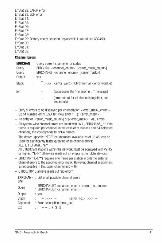
ErrStat 01: Self-test errorErrStat 02: ROM errorErrStat 03: RAM errorErrStat 04: EEPROM A errorErrStat 05: EEPROM B errorErrStat 06: User error AErrStat 07: ErrStat 08: Internal battery errorErrStat 09: ErrStat 10: ErrStat 11: Uv failureErrStat 12: ErrStat 13: ErrStat 14: COM1 communications errorErrStat 15: COM2 communications errorErrStat 16: COM3 communications errorErrStat 17: LAN communications errorErrStat 18: ErrStat 19: ErrStat 20: ErrStat 21: LAN/L error
ERRSTAT : Query current station error statusQuery : ERRSTAT [<error mask enum>]Query : ERRSTAT@ [<error mask>]Output : yesStack : – >>> <error_word>Ext : _ (suppresses the
“no error in ..." message.)
ERRSTATLIST : List of all possible station errorsQuery : ERRSTATLIST <error no. emum> ERRSTATLISTOutput : yesStack : – >>> – <error_no.>Clipboard : Error description (error_no.)Ext : + – . # $ %
GMC-I Messtechnik GmbH 41
ErrStat 22: LAN/R errorErrStat 23: LON errorErrStat 24: ErrStat 25: ErrStat 26: ErrStat 27: ErrStat 28: ErrStat 29: Battery nearly depleted (replaceable Li round cell CR2450)ErrStat 30: ErrStat 31: ErrStat 32:
Channel Errors
– Entry of errors to be displayed per enumeration: <error_mask_enum>,32 bit numeric entry (LSB set: view error 1 ...): <error_mask>
– No entry of [<error_mask_enum>] or [<error_mask>]: ALL errors– All system-wide channel errors are listed with "ALL, ERRCHAN&_ *". One
frame is required per channel: in the case of m stations and 64 activated channels, this corresponds to m*64 frames.
– The device-specific "*ERR" enumeration, available as of V2.45, can be used for significantly faster querying of all channel errors: ALL, ERRCHAN&_ *err All U1601/2/3 stations within the network must be equipped with V2.45 or higher. "*ERR" otherwise reads out an empty list for older devices.
– ERRCHAN* (Ext.'*') requires one frame per station in order to enter all channel errors to the specified error mask. However, channel assignment is not possible in this case (channel info = 0).
– U1600/10/15 always reads out "no error".
ERRCHAN : Query current channel error statusQuery : ERRCHAN <channel_enum> [<error_mask_enum>] Query : ERRCHAN@ <channel_enum> [<error mask>]Output : yes
Stack : – >>> <error_word> (OR’d from all <error word>s)
Ext : _ (suppresses the “no error in ..." message)
* (error output for all channels together, not separately)
ERRCHAN-LIST
: List of all possible channel errors
Query : ERRCHANLIST <channel_enum> <error_no._enum> ERRCHANLIST <channel_enum>
Output : yesStack : – >>> – <error_no.> >>> –Clipboard : Error description (error_no.)Ext : + – . # $ %
42 GMC-I Messtechnik GmbH
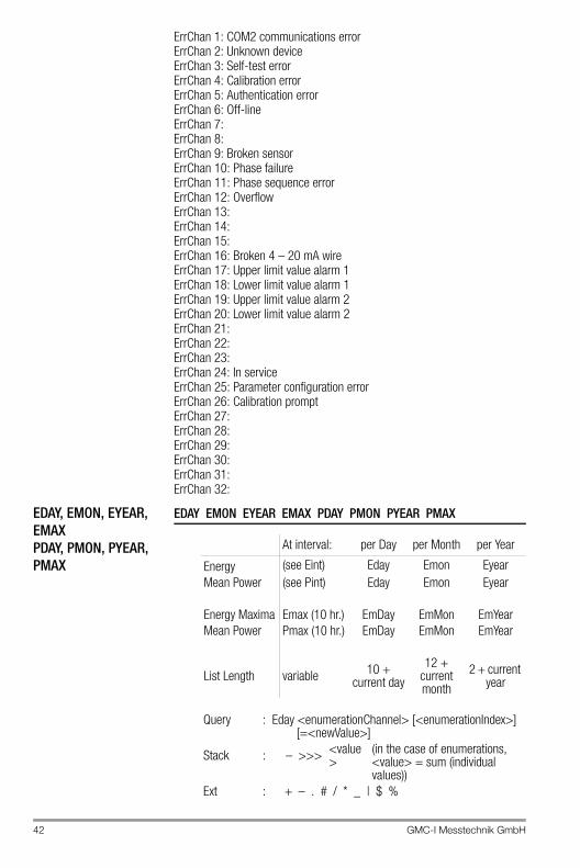
ErrChan 1: COM2 communications errorErrChan 2: Unknown deviceErrChan 3: Self-test errorErrChan 4: Calibration errorErrChan 5: Authentication errorErrChan 6: Off-lineErrChan 7: ErrChan 8: ErrChan 9: Broken sensorErrChan 10: Phase failureErrChan 11: Phase sequence errorErrChan 12: OverflowErrChan 13: ErrChan 14: ErrChan 15: ErrChan 16: Broken 4 – 20 mA wireErrChan 17: Upper limit value alarm 1ErrChan 18: Lower limit value alarm 1ErrChan 19: Upper limit value alarm 2ErrChan 20: Lower limit value alarm 2ErrChan 21: ErrChan 22: ErrChan 23: ErrChan 24: In serviceErrChan 25: Parameter configuration errorErrChan 26: Calibration promptErrChan 27: ErrChan 28: ErrChan 29: ErrChan 30: ErrChan 31: ErrChan 32:
EDAY, EMON, EYEAR, EMAXPDAY, PMON, PYEAR, PMAX
EDAY EMON EYEAR EMAX PDAY PMON PYEAR PMAX
At interval: per Day per Month per Year
Energy (see Eint) Eday Emon EyearMean Power (see Pint) Eday Emon Eyear
Energy Maxima Emax (10 hr.) EmDay EmMon EmYearMean Power Pmax (10 hr.) EmDay EmMon EmYear
List Length variable 10 + current day
12 + current month
2 + current year
Query : Eday <enumerationChannel> [<enumerationIndex>][=<newValue>]
Stack : – >>> <value>
(in the case of enumerations, <value> = sum (individual values))
Ext : + – . # / * _ | $ %
GMC-I Messtechnik GmbH 43
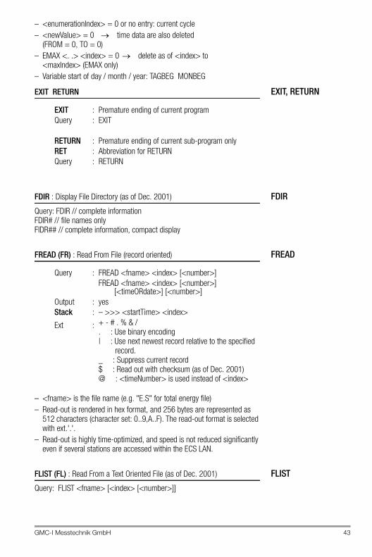
– <enumerationIndex> = 0 or no entry: current cycle– <newValue> = 0 time data are also deleted
(FROM = 0, TO = 0)– EMAX <. .> <index> = 0 delete as of <index> to
<maxIndex> (EMAX only)– Variable start of day / month / year: TAGBEG MONBEG
EXIT, RETURNEXIT RETURN
FDIRFDIR : Display File Directory (as of Dec. 2001)
Query: FDIR // complete informationFDIR# // file names only FIDR## // complete information, compact display
FREADFREAD (FR) : Read From File (record oriented)
– <fname> is the file name (e.g. "E.S" for total energy file)– Read-out is rendered in hex format, and 256 bytes are represented as
512 characters (character set: 0..9,A..F). The read-out format is selected with ext.'.'.
– Read-out is highly time-optimized, and speed is not reduced significantly even if several stations are accessed within the ECS LAN.
FLISTFLIST (FL) : Read From a Text Oriented File (as of Dec. 2001)
Query: FLIST <fname> [<index> [<number>]]
EXIT : Premature ending of current programQuery : EXIT
RETURN : Premature ending of current sub-program onlyRET : Abbreviation for RETURNQuery : RETURN
Query : FREAD <fname> <index> [<number>]FREAD <fname> <index> [<number>]
[<timeORdate>] [<number>]Output : yesStack : – >>> <startTime> <index>
Ext : + - # . % & /. : Use binary encoding| : Use next newest record relative to the specified
record._ : Suppress current record$ : Read out with checksum (as of Dec. 2001)@ : <timeNumber> is used instead of <index>
44 GMC-I Messtechnik GmbH
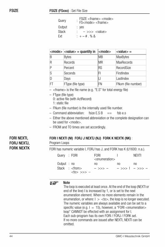
FSIZE FSIZE (FSxxx) : Set File Size
– <fname> is the file name (e.g. "E.S" for total energy file)– FType (file type)
0: active file (with ActRecord)1: static file
– FNum (file number) is the internally used file number.– Command abbreviation: fsize E.S B == fsb e.s– Either the above mentioned abbreviation or the complete designation can
be used for <mode>.– FROM and TO times are set accordingly.
FORI NEXTI,FORJ NEXTJ,FORK NEXTK
FORI I NEXTI (NI) FORJ J NEXTJ (NJ) FORK K NEXTK (NK) : Program Loops
FORI has numeric variable I, FORJ has J, and FORK has K (U1600: n.a.).
NoteThe loop is executed at least once. At the end of the loop (NEXTI or end of the line) I is increased by 1, or is set to the next enumeration element. When no more elements remain in the enumeration, or where: I > <to>, the loop is no longer executed.The numeric variables are always available and can be set to a specific value (e.g. I = 15), however, a “FORI <enumeration> loop” CANNOT be effected with an assignment for I. Each sub-program has its own FORI / FORJ / FORK set. If no more commands are issued after NEXTI, NEXTI can be omitted.
Query : FSIZE <fname> <mode> FS<mode> <fname>
Output : yesStack : – >>> <value>Ext : + – # . % &
<mode> <value> = quantity in <mode> <value> =B Bytes MB MaxBytesR Records MR MaxRecordsP Percent RS RecordSizeS Seconds FI FirstIndexD Days LI LastIndexFT FType (file type) FN FNum (file number)
Query : FORI FORI<enumeration>
I NEXTI
Output : no no no noStack : <from>
<to> >>> –– >>> – – >>> I – >>> –
GMC-I Messtechnik GmbH 45
<enumeration> can encompass a range of 0 to 63 or 1 to 64.FORI* : reversal of the sequential processing order
Examples! Test:, 2,5, FORI, i, !+ " " ., nexti Test: 2 3 4 5! Test:, FORI 2..5, i, !+ " " . Test: 2 3 4 5! Test:, FORI 2..5, i, !+ " %ai" Test: 2 3 4 5! Test:, FORI* 2..5, i, !+ " %ai" Test: 5 4 3 2
FORMATFORMAT : Formatting the Data Logger (queries data with EINT)
– The formatting process organizes the memory for a certain number of interval data channels, although the total depth of memory is dynamically related to the length of the synchronizing interval. If memory is full, data is rotated, i.e. the oldest entry is deleted to make room for the newest.
– Reformatting of the data logger (with delete) only occurs if an <enumeration> is assigned to the FORMAT command. If no assignment has been made, FORMAT reads out current formatting, and the number of storable channels is pushed to the stack.
– Any enumeration is possible (even with virtual channels).– Entries to the data list (except for the current values) are compressed to a
2 byte value at the expense of accuracy. The data range can be flexibly encoded as of ECSys V1.60, in order to adapt the working range in an ideal fashion (see below). Attention: Older ECS versions do not understand the new encoding formats!
– The following applies upon delivery of the instrument: FORMAT = 1 . . 64 0.
Query : FORMAT FORMAT@Stack : – >>> <number_of_channels>
– >>> <encoding><number_of_channels>
Output : Formatting information (not for . and # ##), and list of channels
Ext : + – . # ## @
Query : FORMAT = <enumeration>Formatting according toselected channel and currentencoding
Stack : – >>> –
Query : FORMAT = <enumeration> <encoding>Formatting with predefinedencoding
Stack : – >>> –
46 GMC-I Messtechnik GmbH
Encoding the Data Range: (0: default. resolution specified in [ ])0 : 0...+/-0.8191[0.0001]...+/-81.91[0.01]....+/-8191[1]...+/-819100[100]1 : 0....+/-8.191[0.001]....+/-81.91[0.01]...+/-819.1[0.1]...+/-8191[1]2 : 0....+/-16383[1].......+/-163830[10]3 : 0......+32767[1].........+327670[10]4 : 0..+/-99999999 [8 decimal places, smallest place: 1E-6]
If the number is > 99999999, the leading places are omitted. 1234567890 --> 34567890 omission of the first 2 places 12345678.9 --> 12345679 8th place is 5/4 rounded 1234567.8 --> 1234567.8 no restriction 12.345678 --> 12.345678 no restriction 12.3456789 --> 12.345679 8th place is 5/4 rounded 1.23456789 --> 1.234568 only 6 places after decimal (see below)
Notes– Encoding types 0, 1, 2 and 3 use two bytes per entry, but encoding type
4 uses 4 bytes per entry and memory duration is thus cut in half.– Encoding type 4 is only available as of V2.46, and interval data encoded
per example 4 cannot be read out from stations with older firmware versions!
– With encoding type 4 the smallest resolution is 1E-7, and resolution is 1E-6 with faster read-out using ext.'#' (the 6th place after the decimal is 5/4 rounded if required).
Testing Encoding
HH, MM, SS, DAY, WDAY, MON, YEAR
HH MM SS DAY WDAY MON YEAR :Selective querying of time and date, push result to the stack
Query : DLVAL <w> [<dlcode>] (U1600: l.a.)Output : yesStack : – >>> <w compressed>
HH : Hour (0... 23)MM : Minute (0... 59)SS : Second (0... 59)DAY : Day (1... 31)WDAY : Weekday (1: Monday... 7: Sunday)MON : Month (1... 12)YEAR : Year (90... 99, 0... 20)YEAR* : Year (1990... 1999, 2000... 2020)Query : HH : basis = system timeOutput : noStack : – >>> <hourNumber>Ext : ! _
Query : HH . : basis = second number from stack
Output : noStack : <secNumber> >>> <hourNumber>Ext : ! _
GMC-I Messtechnik GmbH 47
Meanings of Extensions:– Ext. ‘!‘ forces a task:
A number is displayed for HH!, MM!, SS!, DAY!, YEAR!, forWDAY! : name of dayMON! : name of month
– Ext. ‘_‘ accesses the operating hours counter instead of real-time when queried without an argument (U1600: n.a.).
– Ext. ‘–‘ or "– –" : The number or response is saved to the clipboard and no output ensues.
Time Reference– All above listed commands used WITHOUT an argument make reference
to real-time for the station at which the command is physically interpreted (as if ID AA: were always selected). See also ID and TIME. If time at a given station is nevertheless to be used as a reference, proceed as follows:
C5:time–,SS! .: reads out seconds (0 ... 59) for station C5:
Examples– Other definition for weekday numbers (0: Sunday ... 6: Saturday):
WDAY,7,MOD, !– Second count for current day:
TIME–,86400,MOD, !– SS command "on foot" written:
TIME–,86400,MOD,60,MOD, !– MM command "on foot" written:
TIME–,86400,MOD,3600,MOD,60,/,INT, !
H Programs, HLIST, HBREAK
H Programs HLIST HBREAK
Query : H <enumeration> [=<characterString>]Output : no (yes in case of listed exts. except '-' & '?')Clipboard : <program> (except during execution)Stack : - >>> - (except with ext. '?', see below.)Ext. : + - . # $ ! % ?
– H without <index> == H 0, H1..H31 == H 1..H 31, H5! == H! 5– No program execution occurs with extension.– Maximum number of nested programs: 10 (U1600: 3) P programs,
maximum line length: 128
H0 . . H31 : Execute and/or program BACKGROUND programs
H0 ... H31 (U1600: H0 .. H19) are executed in the background one after the other. Run time errors may be flagged with ERR. Output from the background programs is always sent to COM1 at the station on which the background program is running.(Exception: output can also be rerouted to COM2 with the U1600 in COM mode “COM+MIX” or the U1601 in COM mode “ECL+HP”.)Ext : + – . # $ ! % ?
48 GMC-I Messtechnik GmbH
– H 19 is the “print program” and is activated at the control panel. H 19 only runs in the background when activated and not at other times (U1600 only!).
– H? pushes the number (0..31, -1:pause) of the current H program to the stack. This function may only be executed within H programs.
– H?? pushes the following to the stack: 1= focus H program, 0= focus command line. It can thus be determined whether or not a program is executed as an H program.
Listing H ProgramsHLIST : List all H programs, corresponds to: H! *HLIST <enumeration> : corresponds to: H! <enumeration>HLIST* : List all non-empty H programs (1600: l.a.)
– Copying H 7 to H 13: h- 7,H 13=$ orh7-,h13=$
– Copy all H’s to station B: fori 0..31, i,h- ., i,B:h .=$
Interrupt H ProgramsHBREAK Interruption and 16 s pause for background programs.HBREAK+ : Same as HBREAK, but with 32 s pauseHBREAK++ : Same as HBREAK, but with 60 s pauseHBREAK- : Immediately end pause for H programs. (U1600: n.a.)
IF ELSE ENDIF IF ELSE ENDIF (EIF) : Program Branching
The IF command pops an element from the stack and rounds it to the next whole number (5/4). If it is not equal to zero, all commands between IF and ELSE are processed. If it is equal to zero, the portion of the program between ELSE and ENDIF is executed.
– Each sub-program may have up to four nesting levels.– If there are no more commands after ELSE or ENDIF, ELSE / ENDIF can be
omitted.– If the section between IF and ELSE is only to be executed once following
the occurrence of a true condition, use IFF (see IFF).– See TIMECOMPARISON for the use of IF with time comparison.– EIF is the abbreviated form for ENDIF
Example of "condition fulfilled":1, IF, PRINT "This section is executed", ELSE, PRINT "but this is not"
Example of "condition NOT fulfilled":0, IF, PRINT 'NO', ELSE , PRINT "YES", endif; PRINT "Yes/No-finished"
Query : IF ELSE ENDIFStack : <condition> >>> – – >>> – – >>> –
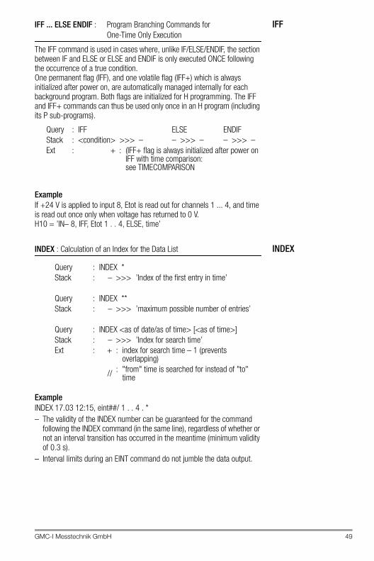
GMC-I Messtechnik GmbH 49
IFFIFF ... ELSE ENDIF : Program Branching Commands for One-Time Only Execution
The IFF command is used in cases where, unlike IF/ELSE/ENDIF, the section between IF and ELSE or ELSE and ENDIF is only executed ONCE following the occurrence of a true condition.One permanent flag (IFF), and one volatile flag (IFF+) which is always initialized after power on, are automatically managed internally for each background program. Both flags are initialized for H programming. The IFF and IFF+ commands can thus be used only once in an H program (including its P sub-programs).
ExampleIf +24 V is applied to input 8, Etot is read out for channels 1 ... 4, and time is read out once only when voltage has returned to 0 V. H10 = ’IN– 8, IFF, Etot 1 . . 4, ELSE, time’
INDEXINDEX : Calculation of an Index for the Data List
ExampleINDEX 17.03 12:15, eint##/ 1 . . 4 . *– The validity of the INDEX number can be guaranteed for the command
following the INDEX command (in the same line), regardless of whether or not an interval transition has occurred in the meantime (minimum validity of 0.3 s).
– Interval limits during an EINT command do not jumble the data output.
Query : IFF ELSE ENDIFStack : <condition> >>> – – >>> – – >>> –Ext : + : (IFF+ flag is always initialized after power on
IFF with time comparison: see TIMECOMPARISON
Query : INDEX *Stack : – >>> ’Index of the first entry in time’
Query : INDEX **Stack : – >>> ’maximum possible number of entries’
Query : INDEX <as of date/as of time> [<as of time>]Stack : – >>> ’Index for search time’Ext : + : index for search time – 1 (prevents
overlapping)
// : "from" time is searched for instead of "to" time
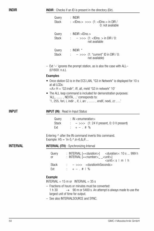
50 GMC-I Messtechnik GmbH
INDIR INDIR : Checks if an ID is present in the directory (Dir).
– Ext ‘–‘ ignores the prompt station, as is also the case with ALL– (U1600: n.a.).
Examples• Once station G3 is in the ECS LAN, "G3 in Network" is displayed for 10 s
at all LCDs: <A> H = ’G3:indir*, iff, all, meld “G3 in network“ 10’
• The ALL loop command is included for demonstration purposes: ’ALL, ....... , NEXTA, ...’ corresponds to: ’1, 255, fori, i, indir ., if, i, an: , ....... , endif, nexti, zz: , ...’
INPUT INPUT (IN) : Read in Input Status
Entering ^ after the IN command inverts this command.Example: H5 = ’in-5,^,in-6,&,iF....
INTERVAL INTERVAL (ITV) : Synchronizing Interval
ExampleINTERVAL = 15 m or INTERVAL = 35 s– Fractions of hours or minutes must be converted:
1 h 30 90 m or 5400 s. An attempt is always made to use the largest unit of time for output.
– See also INTERVALSOURCE and SYNC.
Query : INDIRStack : <IDno.> >>> (1: <IDno.> in DIR /
0: not available
Query : INDIR >IDno.>Stack : – >>> (1: <IDno. > in DIR / 0:
not available
Query : INDIR *Stack : – >>> (1: “current” ID in DIR / 0:
not available)
Query : IN <enumeration>Stack : – >>> (1: 24 V present, 0: 0 V present)Ext : + – . # %
Queryor
::
INTERVAL [=<duration>] <duration>: 10 s ... 999 hINTERVAL [=<number>_ _<unit>]
<unit>: s | m | hStack : – >>> <durationInSeconds>Ext : + – . # | %
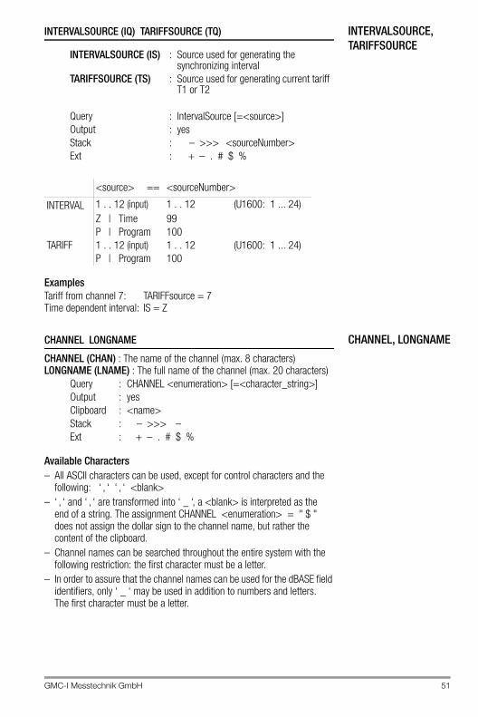
GMC-I Messtechnik GmbH 51
INTERVALSOURCE, TARIFFSOURCE
INTERVALSOURCE (IQ) TARIFFSOURCE (TQ)
ExamplesTariff from channel 7: TARIFFsource = 7Time dependent interval: IS = Z
CHANNEL, LONGNAMECHANNEL LONGNAME
CHANNEL (CHAN) : The name of the channel (max. 8 characters)LONGNAME (LNAME) : The full name of the channel (max. 20 characters)
Available Characters– All ASCII characters can be used, except for control characters and the
following: ‘ , ‘ ‘ , ‘ <blank>– ‘ , ‘ and ‘ , ‘ are transformed into ‘ _ ‘, a <blank> is interpreted as the
end of a string. The assignment CHANNEL <enumeration> = " $ " does not assign the dollar sign to the channel name, but rather the content of the clipboard.
– Channel names can be searched throughout the entire system with the following restriction: the first character must be a letter.
– In order to assure that the channel names can be used for the dBASE field identifiers, only ‘ _ ‘ may be used in addition to numbers and letters. The first character must be a letter.
INTERVALSOURCE (IS) : Source used for generating the synchronizing interval
TARIFFSOURCE (TS) : Source used for generating current tariff T1 or T2
Query : IntervalSource [=<source>]Output : yesStack : – >>> <sourceNumber>Ext : + – . # $ %
<source> == <sourceNumber>
INTERVAL 1 . . 12 (input) 1 . . 12 (U1600: 1 ... 24)Z | Time 99P | Program 100
TARIFF 1 . . 12 (input) 1 . . 12 (U1600: 1 ... 24)P | Program 100
Query : CHANNEL <enumeration> [=<character_string>]Output : yesClipboard : <name>Stack : – >>> –Ext : + – . # $ %
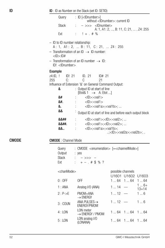
52 GMC-I Messtechnik GmbH
ID ID : ID as Number on the Stack (set ID: SETID)
– ID to ID number relationship:A : 1, A1 : 2, ... B : 11, C : 21, ... Z4 : 255
– Transformation of an ID ID number:<ID>:ID#
– Transformation of an ID number ID:ID! <IDnumber>
Examplez4:ID, ! ID! 21 ID. 21 ID# 21255 C: C 21Influence of Extension ’&’ on General Command Output:
CMODE CMODE : Channel Mode
Query : ID [<IDnumber>]without <IDnumber>: current ID
Stack : – >>> <IDnumber>A: 1, A1: 2, ..., B: 11, C: 21, ... , Z4: 255
Ext : ! + . # %
& : Output ID at start of line[Etot& 1 A: Etot ...]
&# : <ID>:<val1>&#. : <ID>:<val1>&. : <ID>:<val1a>;<val1b>; ...&& : Output ID at start of line and before each output block
&&## : <ID>:<val1>;<ID>:<val2>; ...&&##. : <ID>;<val1>;<ID>;<val2>; ...&&.. : <ID>;<val1a>;<val1b>;
..;<ID>;<val2a>;<val2b>; ..
Query : CMODE <enumeration> [=<channelMode>]Output : yesStack : – >>> –Ext : + – . # $ % ?
<chanMode> possible channelsU1601 U1602 U1603
0 : OFF OFF 1 ... 64 1 ... 64 1 ... 64
1 : ANA Analog I/O (ANA) 1 ... 14 — 1 ... 6+13+14
2 : P->E PMOM=ANA ENERGY
1 ... 12 — 1 ... 6
3 : COUN ANA PULSESENERGY/PMOM
1 ... 12 — 1 ... 6
4 : LON LON meter ENERGY / PMOM 1 ... 64 1 ... 64 1 ... 64
5 : LON LON analog I/O (LONANA) 1 ... 64 1 ... 64 1 ... 64
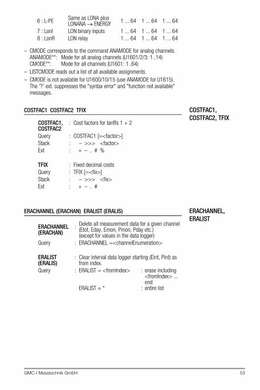
GMC-I Messtechnik GmbH 53
– CMODE corresponds to the command ANAMODE for analog channels.ANAMODE**: Mode for all analog channels (U1601/2/3: 1..14)CMODE**: Mode for all channels (U1601: 1..64)
– LISTCMODE reads out a list of all available assignments.– CMODE is not available for U1600/10/15 (use ANAMODE for U1615).
The '?' ext. suppresses the "syntax error" and "function not available" messages.
COSTFAC1, COSTFAC2, TFIX
COSTFAC1 COSTFAC2 TFIX
ERACHANNEL,ERALIST
ERACHANNEL (ERACHAN) ERALIST (ERALIS)
6 : L-PE Same as LONA plus LONANA ENERGY 1 ... 64 1 ... 64 1 ... 64
7 : LonI LON binary inputs 1 ... 64 1 ... 64 1 ... 648 : LonR LON relay 1 ... 64 1 ... 64 1 ... 64
COSTFAC1,COSTFAC2
: Cost factors for tariffs 1 + 2
Query : COSTFAC1 [=<factor>]Stack : – >>> <factor>Ext : + – . # %
TFIX : Fixed decimal costsQuery : TFIX [=<fix>]Stack : – >>> <fix>Ext : + – . #
ERACHANNEL(ERACHAN)
: Delete all measurement data for a given channel(Etot, Eday, Emon, Pmon, Pday etc.)(except for values in the data logger)
Query : ERACHANNEL =<channelEnumeration>
ERALIST(ERALIS)
: Clear interval data logger starting (Eint, Pint) as from index.
Query : ERALIST = <fromIndex> : erase including <fromIndex> ... end
ERALIST = * : entire list
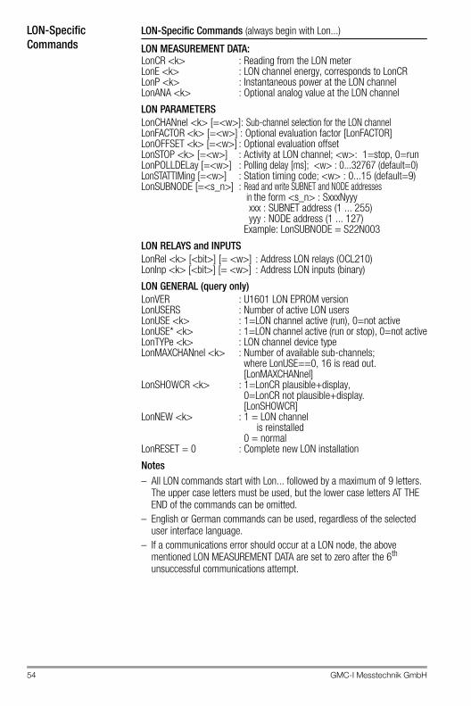
54 GMC-I Messtechnik GmbH
LON-Specific Commands
LON-Specific Commands (always begin with Lon...)
LON MEASUREMENT DATA:LonCR <k> : Reading from the LON meterLonE <k> : LON channel energy, corresponds to LonCRLonP <k> : Instantaneous power at the LON channelLonANA <k> : Optional analog value at the LON channel
LON PARAMETERSLonCHANnel <k> [=<w>]: Sub-channel selection for the LON channelLonFACTOR <k> [=<w>] : Optional evaluation factor [LonFACTOR]LonOFFSET <k> [=<w>] : Optional evaluation offsetLonSTOP <k> [=<w>] : Activity at LON channel; <w>: 1=stop, 0=runLonPOLLDELay [=<w>] : Polling delay [ms]; <w> : 0...32767 (default=0)LonSTATTIMing [=<w>] : Station timing code; <w> : 0...15 (default=9)LonSUBNODE [=<s_n>] : Read and write SUBNET and NODE addresses
in the form <s_n> : SxxxNyyy xxx : SUBNET address (1 ... 255) yyy : NODE address (1 ... 127) Example: LonSUBNODE = S22N003
LON RELAYS and INPUTSLonRel <k> [<bit>] [= <w>] : Address LON relays (OCL210)LonInp <k> [<bit>] [= <w>] : Address LON inputs (binary)
LON GENERAL (query only)LonVER : U1601 LON EPROM versionLonUSERS : Number of active LON usersLonUSE <k> : 1=LON channel active (run), 0=not activeLonUSE* <k> : 1=LON channel active (run or stop), 0=not activeLonTYPe <k> : LON channel device typeLonMAXCHANnel <k> : Number of available sub-channels;
where LonUSE==0, 16 is read out. [LonMAXCHANnel]
LonSHOWCR <k> : 1=LonCR plausible+display, 0=LonCR not plausible+display. [LonSHOWCR]
LonNEW <k> : 1 = LON channelis reinstalled
0 = normalLonRESET = 0 : Complete new LON installation
Notes– All LON commands start with Lon... followed by a maximum of 9 letters.
The upper case letters must be used, but the lower case letters AT THE END of the commands can be omitted.
– English or German commands can be used, regardless of the selected user interface language.
– If a communications error should occur at a LON node, the above mentioned LON MEASUREMENT DATA are set to zero after the 6th unsuccessful communications attempt.
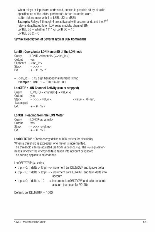
GMC-I Messtechnik GmbH 55
– When relays or inputs are addressed, access is possible bit by bit (with specification of the <bit> parameter), or for the entire word. <bit> : bit number with 1 = LSBit, 32 = MSBit Example: Relays 1 through 4 are activated with a command, and the 2nd relay is deactivated later (LON relay module: channel 36) LonREL 36 = whether 1111 or LonR 36 = 15 LonREL 36 2 = 0
Syntax Description of Several Typical LON Commands
LonID : Query/enter LON NeuronID of the LON nodeQuery : LONID <channel> [=<lon_id>]Output : yesClipboard : <lon_id>Stack : – >>> –Ext. : + – # . % ?
– <lon_id> : 12 digit hexadecimal numeric stringExample : LONID 1 = 01002a201F00
LonSTOP : LON Channel Activity (run or stopped)Query : LONSTOP<channel>[=<value>]Output : yesStack : – >>> <value> <value> : 0=run, 1=stoppedExt. : + – # . % ?
LonCR : Reading from the LON MeterQuery : LONCR<channel>Output : yesStack : – >>> <value>Ext. : + – # . % ?
LonDELTATRIP : Check energy deltas of LON meters for plausibilityWhen a threshold is exceeded, one meter is incremented.The threshold can be adjusted (as from version 2.49). The +/-sign deter-mines whether the energy delta is taken into account or ignored. The setting applies to all channels.
LonDELTATRIP [= <trip>]• trip > 0: if delta > |trip| --> increment LonDELTAOVF and ignore delta• trip < 0: if delta > |trip| --> increment LonDELTAOVF and take delta into
account• trip = 0: if delta > 10 --> increment LonDELTAOVF and take delta into
account (same as for V2.48)
Default: LonDELTATRIP = 1000
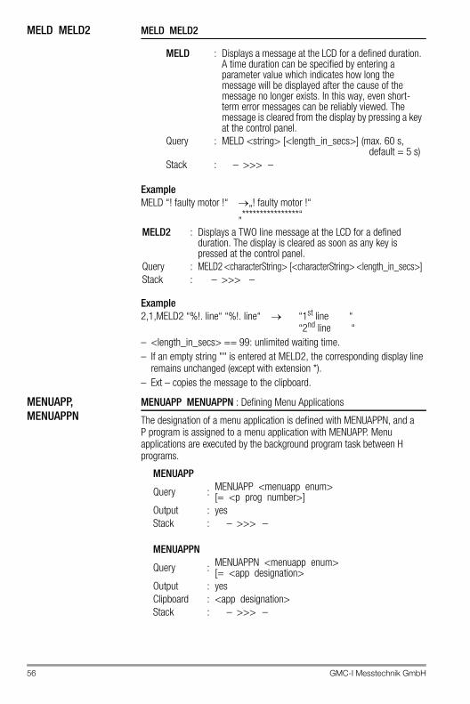
56 GMC-I Messtechnik GmbH
MELD MELD2 MELD MELD2
ExampleMELD “! faulty motor !“ „! faulty motor !“
„****************“
Example2,1,MELD2 “%!. line“ “%!. line“ “1st line “
“2nd line “– <length_in_secs> == 99: unlimited waiting time.– If an empty string "" is entered at MELD2, the corresponding display line
remains unchanged (except with extension *).– Ext – copies the message to the clipboard.
MENUAPP, MENUAPPN
MENUAPP MENUAPPN : Defining Menu Applications
The designation of a menu application is defined with MENUAPPN, and a P program is assigned to a menu application with MENUAPP. Menu applications are executed by the background program task between H programs.
MELD : Displays a message at the LCD for a defined duration. A time duration can be specified by entering a parameter value which indicates how long the message will be displayed after the cause of the message no longer exists. In this way, even short-term error messages can be reliably viewed. The message is cleared from the display by pressing a key at the control panel.
Query : MELD <string> [<length_in_secs>] (max. 60 s, default = 5 s)
Stack : – >>> –
MELD2 : Displays a TWO line message at the LCD for a defined duration. The display is cleared as soon as any key is pressed at the control panel.
Query : MELD2 <characterString> [<characterString> <length_in_secs>] Stack : – >>> –
MENUAPP
Query : MENUAPP <menuapp enum>[= <p prog number>]
Output : yesStack : – >>> –
MENUAPPN
Query : MENUAPPN <menuapp enum>[= <app designation>
Output : yesClipboard : <app designation>Stack : – >>> –
GMC-I Messtechnik GmbH 57
– 3 times 5 applications are available.Range of <menuapp enum>: Applications (1) : 1 . . 5Applications (2) : 6 . . 10Applications (3) : 11 . . 15
– <p prog number> is the number of the assigned P program (0 . . 31). If no action is initialized, –1 must be assigned.
– <app designation> may not exceed a length of 10 characters, and blanks, ‘,‘ and ‘;‘ may not be used.
– U1600/10/15: MENUAPP/MENUAPPN are not available. Background program H 19 is used as a so-called print output.
MENUEDITMENUEDIT : Allows for editing in menu applications (U1600: n.a.)
Query: MENUEDIT <mode> <n> = <title> [<lower value> [<upper value>]]Output: no <mode> : Variable A | a | B | bStack: – >>> – <n> : Index of Var. A or BExt. : @ <title> : Title string (max. 16 char.)
<lower value> : Lower numeric value<upper value> : Upper numeric value
– Ext. '@' allows for the rejection of zero values.– Editing is only possible when the application menu is open, which means
that 100 must always be added to the MenuApp program number.– Example: A 14 contains a value for limit value alarm 1, and A 15 contains
the value for alarm 2. A14 and A15 can now be edited with F4 and F5 in the 1st application menu under consideration of certain upper and lower values.
MenuApp 04 = 114MenuApp 05 = 115MenuAppN 04 = 'Alarm 1'MenuAppN 05 = 'Alarm 2'P 14 = 'MenuEdit a 14 = "Alarm 1 [1..40]" 1 40'P 15 = 'MenuEdit a 15 = "Alarm 2 [1..50]" 1 50'
58 GMC-I Messtechnik GmbH
FEATURES FEATURES: Query all Features
Query : FEATURE <name> [= <value> [<enable>]] FEATURES Query all enabled features (<value> != 0) FEATURES * Query all available features
Output : yesClipboard : <name> FEATURES : <last_name>Stack : – >>> <value>FEATURES : - >>> <sum_all_values>Ext. : + – & $ # .
– The availability of features depends upon the device type. Each feature has a give <value> range. If a feature is deactivated, its <value> is always equal to 0. Under normal circumstances, device features are set in accordance with customer requirements when the device is purchased. Nevertheless, some features can be modified by the user (<value> not equal to 0), and some can be fully configured (<value> : 0,1,2,..).
– If an <enabling> code is required, temporary disabling may occur if an incorrect code is entered several times.
MONBEG MONBEG : Variable Beginning of Month / Year
Each month can start on any day, each year can start with any month. The variable mode is active after any assignment is made. The beginning of a day can be selected with DAYBEG.
– The optional entry of <toYear> allows for simultaneous processing of several years (U1600: n.a.).
MONBEG@ = 0 : return to normal operation (always start on the first).MONBEG@@ = 0 : return to normal operation, reset entries.MONBEG@ = 1 : variable mode with previous entries.MONBEG@ : – >>> <state> <state> : 0 = normal, 1 = variable mode
Examples(if <year> is omitted the current year is used)MONBEG 1..12 = 17: months 1 ... 12 begin on the 17th of the month.MONBEG 0 = 10: the year starts in October (here: 17.10.)MONBEG 0 1995 = 2: 1995 starts in February
Query : MONBEG <monthEnumeration> [<year>][=<startDay>]
Stack : – >>> <startDay><year> : 90 ... 99, 0 ... 30
or 1990 ... 2030Ext : – . # &
GMC-I Messtechnik GmbH 59
NF4I, NF4M, NF8I, NF8M, NFSTD
NF4I, NF4M, NF8I, NF8M, NFSTD : Output of REAL Numbers in 32 or 64 Bit IEEE HEX Format
Switching to the desired output format is valid for the rest of the line.
Global output format changes effect all numeric output for the rest of the line: REAL value outputs: !, <command>% "%w", primary value outputs: Ext ‘#‘– Output in the various IEEE HEX formats can be generated without
switching formats by using freely selectable formatting as follows:
Entry of REAL Numbers in 32 or 64 Bit IEEE HEX Format:
– The NF .. command is used for input and output of numbers in 32 or 64 bit IEEE format (the station works internally with these number formats). The 4 or 8 bytes are displayed as 8 or 16 digit HEX numbers (2 characters 0 . . 9+a . . f per byte), i.e. 32 bit floating numbers have 8 characters (4 byte, nf4i or nf4m), and 64 bit double numbers have 16 characters (8 byte, nf8i or nf8m).
– Read-outs with NF . . are significantly faster than standard read-outs with several decimal places.
– MOTOROLA byte ordering (nf4m or nf8m) starts at the left with the MSBit, and ends with the LSBit at the right:
Example
NF4I : Output of REAL numbers (4 byte FLOAT) in 32 bit IEEE HEX formatINTEL byte ordering, 8 HEX characters
NF4M : Output of REAL numbers (4 byte FLOAT) in 32 bit IEEE HEX formatMOTOROLA byte ordering, 8 HEX characters
NF8I : Output of REAL numbers (8 byte DOUBLE) in 64 bit IEEE HEX formatINTEL byte ordering, 16 HEX characters
NF8M : Output of REAL numbers (8 byte DOUBLE) in 64 bit IEEE HEX formatMOTOROLA byte ordering, 16 HEX characters
NFSTD : Reset to default output
<command>% "%4_ _ _w" : INTEL FLOAT HEX<command>% "%8_ _ _w" : INTEL DOUBLE HEX<command>% "%4_ _w" : MOTOROLA FLOAT HEX<command>% "%8_ _w" : MOTOROLA DOUBLE HEX
Stack:NF4I <float_hex_intel> : – >>> <real>NF4M <float_hex_motorola> : – >>> <real>NF8I <double_hex_intel> : – >>> <real>NF8M <double_hex_motorola> : – >>> <real>
INTEL: B7 . . B0 B15 . . B8 B23 . . B16 B31 . . B24MOTOROLA: B31 . . B24 B23 . . B16 B15 . . B8 B7 . . B0
nf4i, 12345678, ! 4E613C4B (INTEL)nf4i 4E613C4B, ! 12345678nf4m, 12345678, ! 4B3C614E (MOTOROLA)nf4m 4B3C614E, ! 12345678
60 GMC-I Messtechnik GmbH
PASSWORD PASSWORD : Secure Access to the Station via RS 232 / ECS LAN
One master user (user 1) and four additional users (2 ... 5) can each have different passwords (numbers ranging from 1 to 999999999). The master user sets access authority for the individual users. Each user may change his own password, as long as the old password is known. The master’s access authority is valid when no users are logged on, or if timeout has expired. The master always has all rights (=5). Initially, all passwords are set to 0. Only the master can change 0 passwords. To delete all passwords: master password = 0.
Attention!!Incorrect entries may result in temporary disabling!
<user> : 1=master=user–1, 2 ... 5=user–2 ... 5, 0=current user
<password> : 1 .. 999999999, 0:delete<pw_old> : Old password or master password as authority<pw_new> : New password (must be entered twice)<rights> : Access authority, see below<timeout> : in minutes 0=no timeout<free> : 1=free (enabled) 0=not free (disabled)<com_i> : COM access: 1=COM–1,
2=COM–2, 0=current access
LOGIN : Log in with a passwordQuery : LOGIN <user> <password>Output : yesStack : – >>> –
LOGOUT : Log outQuery : LOGOUTOutput : noStack : – >>> –
WHOAMI : Query user number and access authority (Who am I)Query : WHOAMIOutput : yesStack : – >>> –
GMC-I Messtechnik GmbH 61
– If ‘ * ‘ is used for the read-out of lists, stack values make reference to the first displayed element. Summation is not sensible in this case.
The PASSWORD also pushes <com_i> to the stack during read-out. If ext ’|’ is used. <com_i> is only defined for the current user (1:COM1, 2:COM2), otherwise zero is pushed to the stack (U1600: n.a.).
NoteSystem-Wide Password Management The PASSWORD command is system-wide, i.e. all access authorities can be managed from a single station. However, access disabling ONLY EFFECTS ACCESS VIA THE LOCAL RS 232. When a user logs on, his access authority for the local station, as well as all other stations within the ECS LAN, is determined by his password (see below). The passwords, rights and timeouts of the station at which the user logged on apply. Care must thus be taken when passwords are issued to make certain that the address context makes reference to the local station (special ID AA:), when the PASSWORD command is executed.Use of the special ID AA:PASSWORD ... thus provides for effective protection against side-effects.
Password : Set up station passwords and access authority
Query : PASSWORD <user> <pw_old> = <pw_new> <pw_new> <rights><timeout>
PASSWORD <user> <pw_old> = <pw_neu> <pw_new>
PASSWORD* <user> <pw_old> =<rights> <timeout>
Stack : – >>> –Query : PASSWORD Read out current user
PASSWORD <user> Read out authority assigned to <user>
PASSWORD * Read out authority assigned to <user> 1 .. 5
Stack : – >>> <timeout> <rights> <user>
PWLRELEASE: Enable specific ECL COM access rights (U1600: n.a.)(PWLREL) From password protection (PasswordLockRelease)Query : PWLRELEASE <com_i> <master_pw> = <free>Query : PWLRELEASE <com_i>Output : yesStack : – >>> <free>
PASSWORD |Stack: – <com_i> <timeout> <rights> <user>
62 GMC-I Messtechnik GmbH
Enabling Individual ECL Access:– U1600/10/15 have only one ECL access port (COM1). The same
passwords and access authorities/timeouts are used for stations with several ECL access ports, although the status of each access port is entirely independent of the other(s). User 2 can thus log on to COM1, and user 5 to COM2. If the current user is queried, the access port must be specified. If no specification is made, the current access port applies (like WHOAMI, except with stack output).
Control Panel Passwords– Control panel passwords can also be changed with PASSWORD. The following
<user> numbers are used to this end. (U1600: n.a.):
Access authority and timeouts cannot be changed. The following applies, as is also the case for ECL passwords: The master (user 1) can change all control panel passwords, and the other users can only change their own passwords. A control panel password is deleted by entering 0 or 111111. If the master control panel password is deleted, the other control panel passwords are still valid, although access protection is disabled.
NoteControl panel passwords are not identical to ECL passwords. U1600/10/15 stations recognize only one control panel password, which is addressed with <user> number 101 or 99.
Example (observe correct sequence!)Master enters:
PASSWORD 1 0=123 123 0 5 : Master pw = 123, timeout = 5 m, 0 user rights = 0
PASSWORD 2 123=222 222 3 10: user 2 pw = 222,timeout = 10 m, rights = 3
PASSWORD* 2 123=2 5 : change rights = 2 and timeout = 5 m
User changes own password:PASSWORD 2 222=2121 2121: change password
User logs on:LOGIN 2 2121
Master deletes all passwords: PASSWORD 1 123=0 0
PASSWORD 0 <com_i> Read out current user at <com_i>PASSWORD 0 2 Read out current user at COM2PASSWORD 0 * Read out current user at COM1+2
101 : user 1 (master)102 .. 105 : user 2 ... user 5
Access Authority Local ECS LAN Notation
Read Write Read Write0 – – – – [– – L: – –]1 yes – – – [r– L: – –]2 yes – yes – [r– L: r –]3 yes yes – – [rw L: – –]4 yes yes yes – [rw L: r –]5 yes yes yes yes [rw L: r w]
GMC-I Messtechnik GmbH 63
PAUSEPAUSE (PP) : Pause in Seconds
The execution of the program is suspended for n seconds – fractions of seconds may also be specified. The effective waiting time is always a multiple of 100 ms.
NoteMaximum length of the pause = 20 s. Numbers with n > 20 are regarded as milliseconds. Example: ’Pause 2.2’ corresponds to ’Pause 2200’, program execution is suspended for 2.2 seconds.
LEVELLEVEL : Sets sensitivity at the meter inputs.
Switching threshold: 0=10%, 1=25% (default), 2=50%, 3=70% offull range.
– The level setting applies to all meter inputs.– Level recognition has an accuracy of 5% and an hysteresis of 1% of full
range.– Other assignments apply to U1600 stations:
The maximum H input level (without hysteresis) can be set within a range of approximately 3 V (Lo) and 5.5 V (Hi) (typical).
PFACTORPFACTOR : Factor used in calculating power from energy per period
This factor can be used to adapt the time reference to the calculation of power.– Normally, the hourly reference is used (kWh to kW) : Pfactor = 3600– Where reference to seconds is required (Ws to W) : Pfactor = 1Formula for calculating power P from energy E andtime span dt: P = E * Pfactor/dt
Query : PAUSE or PAUSE <value>Stack : <value> >>> – – >>> –
Query : LEVEL [=<value>]Output : yesStack : – >>> <value> (only when reading)Ext : + – % <value> : 0 (Lo) ... 3 (Hi),
default: 1
Query : PFACTOR <enumeration> [=<value>]Stack : – >>> <value> (when reading)Ext : + – # . %
64 GMC-I Messtechnik GmbH
POWERFAIL POWERFAIL (PWR) : List of Auxiliary Power Interruptions (max. 32 entries)
– List of all interruptions : PWR * (starting with the first power failure)
– Reverse order of output with ext ‘ * ‘ : PWR* *– Erase, for example, as of index 7 : PWR 7=0– FROM and TO for the last listed failure are always set (even without
extension " / ").– Duration of last interruption [s] : PWR–,DUR, !– Formatting : %w corresponds to the respective failure duration [s], and
%e to unit of measure " s " (U1600: n.a.).
POWERFAIL | POWERFAIL | : Like POWERFAIL, Total Failure Time Stack (U1600: n.a.)
POWERFAIL@ (PWR@)
POWERFAIL@ : Indicates Interval <PowerON> . . <now> see also POWERON]
– Determination of ON-time [s] since PowerOn : PWR@– ,DUR, !
POWERON POWERON (PWRO) :Operating Time since last PowerOn or Reset
– FROM and TO are always set (even without extension /).
Query : POWERFAIL <enumeration> [=0]Output : yesStack : – >>> –Ext : + – # . / * %
| @ (see below)
Query : POWERFAIL | <enumeration> [=0]Output : yesStack : – >>> <sum_of_failure_times>Ext : + – # . / * %
Query : POWERFAIL@Output : yesStack : – >>> –Ext : + – # . / | %
Query : POWERONStack : – >>> <time_in_seconds>Ext : + – # . / $ %
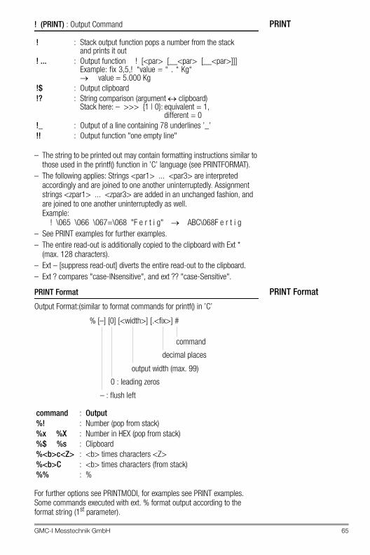
GMC-I Messtechnik GmbH 65
PRINT! (PRINT) : Output Command
– The string to be printed out may contain formatting instructions similar to those used in the printf() function in ’C’ language (see PRINTFORMAT).
– The following applies: Strings <par1> ... <par3> are interpreted accordingly and are joined to one another uninterruptedly. Assignment strings <zpar1> ... <zpar3> are added in an unchanged fashion, and are joined to one another uninterruptedly as well. Example:
! \065 \066 \067=\068 "F e r t i g" ABC\068F e r t i g– See PRINT examples for further examples.– The entire read-out is additionally copied to the clipboard with Ext *
(max. 128 characters).– Ext – [suppress read-out] diverts the entire read-out to the clipboard.– Ext ? compares "case-INsensitive", and ext ?? "case-Sensitive".
PRINT FormatPRINT Format
Output Format:(similar to format commands for printf() in ’C’
For further options see PRINTMODI, for examples see PRINT examples.Some commands executed with ext. % format output according to the format string (1st parameter).
! : Stack output function pops a number from the stack and prints it out
! ... : Output function ! [<par> [__<par> [__<par>]]]Example: fix 3,5,! “value = “ . “ Kg“ value = 5.000 Kg
!$ : Output clipboard!? : String comparison (argument clipboard)
Stack here: – >>> {1 | 0}: equivalent = 1,different = 0
!_ : Output of a line containing 78 underlines ’_’!! : Output function "one empty line"
command : Output%! : Number (pop from stack)%x %X : Number in HEX (pop from stack)%$ %s : Clipboard%<b>c<Z> : <b> times characters <Z>%<b>C : <b> times characters (from stack)%% : %
command
decimal places
output width (max. 99)
0 : leading zeros
– : flush left
% [–] [0] [<width>] [.<fix>] #
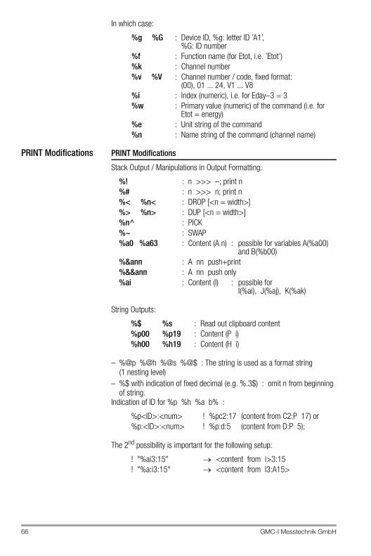
66 GMC-I Messtechnik GmbH
In which case:
PRINT Modifications PRINT Modifications
Stack Output / Manipulations in Output Formatting:
String Outputs:
– %@p %@h %@s %@$ : The string is used as a format string (1 nesting level)
– %$ with indication of fixed decimal (e.g. %.3$) : omit n from beginning of string.
Indication of ID for %p %h %a b% :
The 2nd possibility is important for the following setup:
%g %G : Device ID, %g: letter ID ’A1’,%G: ID number
%f : Function name (for Etot, i.e. ’Etot’)%k : Channel number%v %V : Channel number / code, fixed format:
(00), 01 ... 24, V1 ... V8%i : Index (numeric), i.e. for Eday–3 = 3%w : Primary value (numeric) of the command (i.e. for
Etot = energy)%e : Unit string of the command%n : Name string of the command (channel name)
%! : n >>> –; print n%# : n >>> n; print n%< %n< : DROP [<n = width>]%> %n> : DUP [<n = width>]%n^ : PICK%~ : SWAP%a0 %a63 : Content (A n) : possible for variables A(%a00)
and B(%b00)%&ann : A nn push+print%&&ann : A nn push only%ai : Content (I) : possible for
I(%ai), J(%aj), K(%ak)
%$ %s : Read out clipboard content%p00 %p19 : Content (P i)%h00 %h19 : Content (H i)
%p<ID>:<num> ! %pc2:17 (content from C2:P 17) or%p:<ID>:<num> ! %p:d:5 (content from D:P 5);
! "%ai3:15" <content from i>3:15! "%a:i3:15" <content from I3:A15>
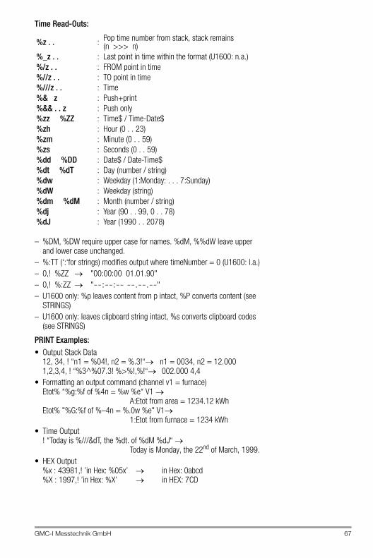
GMC-I Messtechnik GmbH 67
Time Read-Outs:
– %DM, %DW require upper case for names. %dM, %%dW leave upper and lower case unchanged.
– %:TT (‘:‘for strings) modifies output where timeNumber = 0 (U1600: l.a.)– 0,! %ZZ "00:00:00 01.01.90"– 0,! %:ZZ "--:--:-- --.--.--"– U1600 only: %p leaves content from p intact, %P converts content (see
STRINGS)– U1600 only: leaves clipboard string intact, %s converts clipboard codes
(see STRINGS)
PRINT Examples:• Output Stack Data
12, 34, ! “n1 = %04!, n2 = %.3!“ n1 = 0034, n2 = 12.0001,2,3,4, ! “%3^%07.3! %>%!,%!“ 002.000 4,4
• Formatting an output command (channel v1 = furnace)Etot% “%g:%f of %4n = %w %e“ V1
A:Etot from area = 1234.12 kWhEtot% "%G:%f of %–4n = %.0w %e" V1
1:Etot from furnace = 1234 kWh• Time Output
! “Today is %///&dT, the %dt. of %dM %dJ“ Today is Monday, the 22nd of March, 1999.
• HEX Output%x : 43981,! ’in Hex: %05x’ in Hex: 0abcd%X : 1997,! ’in Hex: %X’ in HEX: 7CD
%z . . : Pop time number from stack, stack remains (n >>> n)
%_z . . : Last point in time within the format (U1600: n.a.)%/z . . : FROM point in time%//z . . : TO point in time%///z . . : Time%& z : Push+print%&& . . z : Push only%zz %ZZ : Time$ / Time-Date$%zh : Hour (0 . . 23)%zm : Minute (0 . . 59)%zs : Seconds (0 . . 59)%dd %DD : Date$ / Date-Time$%dt %dT : Day (number / string)%dw : Weekday (1:Monday: . . . 7:Sunday)%dW : Weekday (string)%dm %dM : Month (number / string)%dj : Year (90 . . 99, 0 . . 78)%dJ : Year (1990 . . 2078)
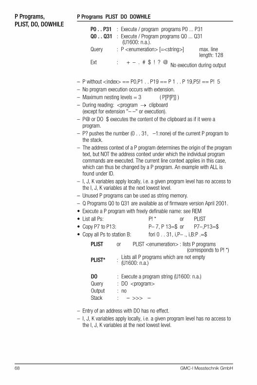
68 GMC-I Messtechnik GmbH
P Programs,PLIST, DO, DOWHILE
P Programs PLIST DO DOWHILE
– P without <index> == P0,P1 . . P19 == P 1 . . P 19,P5! == P! 5– No program execution occurs with extension.– Maximum nesting levels = 3 ( P[P[P]] )– During reading: <program clipboard
(except for extension "– –" or execution).– P@ or DO $ executes the content of the clipboard as if it were a
program.– P? pushes the number (0 . . 31, –1:none) of the current P program to
the stack.– The address context of a P program determines the origin of the program
text, but NOT the address context under which the individual program commands are executed. The current line context applies in this case, which can thus be changed by a P program. An example with ALL is found under ID.
– I, J, K variables apply locally, i.e. a given program level has no access to the I, J, K variables at the next lowest level.
– Unused P programs can be used as string memory. – Q Programs Q0 to Q31 are available as of firmware version April 2001.• Execute a P program with freely definable name: see REM• List all Ps: P! * or PLIST• Copy P7 to P13: P– 7, P 13=$ or P7–,P13=$• Copy all Ps to station B: fori 0 . . 31, i,P– ., i,B:P .=$
– Entry of an address with DO has no effect.– I, J, K variables apply locally, i.e. a given program level has no access to
the I, J, K variables at the next lowest level.
P0 . . P31 : Execute / program programs P0 ... P31Q0 . . Q31 : Execute / Program programs Q0 ... Q31
(U1600: n.a.).Query : P <enumeration> [=<string>] max. line
length: 128Ext : + – . # $ ! ? @ No execution during output
PLIST or PLIST <enumeration> : lists P programs (corresponds to P! *)
PLIST* : Lists all P programs which are not empty (U1600: n.a.)
DO : Execute a program string (U1600: n.a.)Query : DO <program>Output : noStack : – >>> –
GMC-I Messtechnik GmbH 69
– A number is popped from the stack and is rounded up to the next whole number (5/4). If this number is not equal to zero, the <program> is executed. After execution, another number is popped from the stack and the procedure is repeated until the number is equal to zero.
– Entry of an address with DOWHILE has no effect.– I, J, K variables apply locally, i.e. a given program level has no access to
the I, J, K variables at the next lowest level.
ExampleCountdown from 10 to 1:10, dup, dowhile ‘! "still ,1,–,dup‘
RELAY, S0RELAY, RELAYMODE
RELAY SORELAY RELAYMODE
– Ext * always suppresses the optional relay name (see RELAYNAME).
– Ext @ with REL (REL@ <enumeration>) indicates actual relay status taking RELAYMODE overrides into consideration.
DOWHILE (DOWH)
: Execution of a program string, as long as a condition is fulfilled (U1600: n.a.)
Query : DO <program>Output : noStack : <condition> >>> –
RELAY (REL) : 4 outputs switched with relays (changeover contacts) 1 ... 4 are available. ’1’: relay active, ’0’: relay inactive
Query : REL <enumeration> [={1 | 0}]Output : yesStack : – >>> {1 | 0} (when reading)Ext : + – . # * $ % @
SORELAY (SOREL) : S0 relay (semiconductor relay) output switching
(U1600: l.a.)Query : S0REL <enumeration> [={1 | 0}]Output : yesStack : – >>> {1 | 0} (when reading)Ext : + – . # * $ % @
RELAYMODE(RELM)
: Select operating mode for relay outputs: 0: Relay always OFF1: Relay always ON2: Relay controlled with program (default setting)
Query : RELM <enumeration> [=<mode>]Output : yesStack : – >>> <mode> (when reading)Ext : + – . # * %
70 GMC-I Messtechnik GmbH
– The name of a relay can be indicated instead of the <enumeration> (see RELAYNAME, FINDER). S0RELAY then functions as RELAY.
– The stations are equipped as follows: U1600 : 4 relay outputs (changeover contacts) REL 1 . . 4 U1601 : 2 relay outputs (changeover contacts) REL 1 . . 2,
4 semiconductor relay outputs (normally open) REL 3 . . 6 (S1 <– –> REL 3, S2 <– –> REL 4,S3 <– –> REL 5, S4 <– –> REL 6)
– U1615 : max. 7 relay outputs (normally open) REL 1 . . 7 (see ANARELMAP)
– Semiconductor relay outputs (if present) can be controlled directly with S0REL. For the U1601: S0REL 1 corresponds to REL 3. For instruments without dedicated S0 relays: S0REL 1 corresponds to REL 1. Mode and name settings must be selected via RELAYMODE / RELAYNAME, and the relay number must be corrected accordingly.
– The following appears at the STATUS display:’p’ : OFF per program ’P’ : ON per program ’_’ : always OFF (mode 0) ’+’ : always ON (mode 1) ‘–‘ : OFF ‘*‘ ‘*‘ : ON
S0Pxxxx S0Pxxxx Commands for Pulse Output to S0 Relays:(as of March 2002)
: <s0rel> : 1..4 (command SORELAY see above)S0PCH <s0rel> [=<chan>]: Etot channel as basis (0=off, 1..64)S0PDElta <s0rel> [=<delta>]
: deltaE per pulse (0=off) corresponding to the unit for <chan>S0PMS <s0rel> [=<pulse_duration_ms>] : pulse duration in ms (0..1000)
values < 20 ms 20 msminimum cycle duration = 2 * S0PMS
S0PULSe <s0rel> [<cycle_duration_ms>] = <number_of_pulses>: output of <number_of_pulses> pulses withcorresponding cycle duration independent ofS0PCH and/or S0PDElta values. S0PMS is considered.<cycle_duration_ms>: not specified or < 20 ms 2 * S0PMS
– Lower case letters in command names are optional. S0PULS and S0PULSE are thus both valid names for the same command.
– An Etot comparison register is maintained internally which can be read with the S0PETOT <s0rel> command used for test purposes. If an energy difference occurs which is equivalent to more than 250 pulses, the difference is zeroed out (S0PETOT=ETOT) and no pulses are read out. Otherwise, the number of pulses to be read out is calculated based upon the energy difference and the Etot comparison register S0PETOT is adapted accordingly. Number of pulses = Int (ETOT-S0PETOT / S0PDElta) Comparison is performed several times per second.
– Observe the following: S0PDELTA is reciprocal to MCONST (where: EUnit = kWh, URAT = IRAT = 1) MCONST: <mconst> pulses per kWh S0PDELTA: <s0pdelta> kWh per pulse
GMC-I Messtechnik GmbH 71
– S0PDElta may also be negative, and can thus react to negative differences, for example in order to monitor export instead of import.
– Power information from the pulse output: Information regarding power can be derived from the pulse output by means of a special process. If more than one pulse is to be read out, no pulse trains are read out. Instead, the pulse interval is calculated based upon the difference generated for current PMOM (pulse trains are nevertheless generated for channels where PMOM = 0). If sudden delta peaks are detected, the current pulse interval is shortened accordingly so that quick adjustment to the new PMOM situation can ensue. If one or two pulses are to be read out after the performance of a comparison, and if pulses still need to be read out for the last comparison (total of n pulses), these n pulses are uniformly distributed over a period of 10 s, in which case the following applies: n * cycle duration > 10 s (cycle duration calculated from greatest PMOM of all accumulated pulses). The accuracy of power determined based upon pulse interval depends upon several factors: pulse output frequency, channel mode (meter pulses, PE conversion), interval for any linked DVIRT generation (cycle time of the H programs) etc. Although power is calculated as accurately as possible, the power value should only be used as an estimate, but the energy value is (nearly) error-free (64 bit double calculation accuracy, time delay and pulse losses may result from auxiliary power failures).
– Default values: S0PCH 1..4 = 0, S0PDE 1..4=0, S0PMS 1..4=0, S0PETOT 1..4=0
– Example: Channel 1 counts pulses at 1 pulse per kWh. ETOT from channel 1 serves as a basis for pulse output at S0 relay 1 (1 kWh per pulse). This is fed to channel 2 via the 24 V output. Register contents from registers not mentioned here correspond to the default values.
CMODE 1+2 = 3 PE, MCONST 1+2 = 1, PULSE 1+2 = 10 ms S0PCH 1 = 1, S0PDELTA = 1 kWh, S0PMS = 20 ms
Set to start-up status (for test purposes only!): StartStop 1+2 = 0, ETOT 1+2 = 0, S0PETOT 1 = 0, StartStop 1+2 = 1
All meter pulses at channel 1 are now read out via S0 relay 1, and are counted by channel 2 (max. frequency 25 Hz). PMOM measured by channel 2 corresponds to PMOM at channel 1 within the framework described above.
RELAYNAMERELAYNAME (RELN) : Name of a Relay
A name can be assigned to each relay for improved identification.
– Max. length of <name> = 8 characters– The relay name is very useful for searches (see FINDER).– Delete an unused name: RELN 2 = ““
Query : RELN <enumeration> [=<name>]Stack : – >>> –Ext : + – . # %
72 GMC-I Messtechnik GmbH
REM REM / @ : Insert a Remark
ExampleREM "Mean Value Program"@ determines upper valueREM one two three (one string per <par>)– Disregard a Program Line
If a line starts with '#', the line is entirely ignored. H programs can be deactivated very easily in this way, without deleting any content.
– Execute a P Program with a User Definable NameIf the first command in a P program is a special remark "@@ prog_name", this program may be executed by simply typing prog_name instead of P n, even if the program is located elsewhere in the ECS LAN.
ExampleP 10 = '@@ Hello, ! "Hello, how are you?"'Query: hello Output: Hello, how are you?
LPSEARCH : Limited P search, restriction of the system-wide program search (as of Dec. 2001)
Query:LPSEARCH = 0 Searches first at the station with the current address, and
then at all other stations within the LAN (starting with A:..Z4:) DEFAULT.
LPSEARCH = 1 Searches first at the station with the current address, then at the prompt station (ZZ:), and finally at the RS 232 station (AA:).
Output: yesStack: – >>> <lpsearch>Restriction of system-wide program searches (LPSEARCH = 1) is very useful in large networks, because incorrectly written commands would otherwise result in long waiting times.
SET... SET... : Sets the Interfaces
Setting COM, LAN and LON interfaces:SETCOM1 [= <param> [<dly]] : COM 1 serial interfaceSETCOM2 [= <param> [<dly]] : COM 2 serial interfaceSETLANL [= <param> [<dly]] : ECS LAN LEFTSETLANR [= <param> [<dly]] : ECS LAN RIGHTSETLON [= <param>] : LON network (if available)SETCOMS : read out all interface settings
Output : yesClipboard : Parameter stringStack : – >>> –Ext : & + - # % $ ?
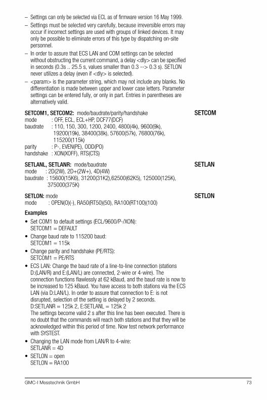
GMC-I Messtechnik GmbH 73
– Settings can only be selected via ECL as of firmware version 16 May 1999.– Settings must be selected very carefully, because irreversible errors may
occur if incorrect settings are used with groups of linked devices. It may only be possible to eliminate errors of this type by dispatching on-site personnel.
– In order to assure that ECS LAN and COM settings can be selected without obstructing the current command, a delay <dly> can be specified in seconds (0.3s .. 25.5 s, values smaller than 0.3 --> 0.3 s). SETLON never utilizes a delay (even if <dly> is selected).
– <param> is the parameter string, which may not include any blanks. No differentiation is made between upper and lower case letters. Parameter settings can be entered fully, or only in part. Entries in parentheses are alternatively valid.
SETCOMSETCOM1, SETCOM2: mode/baudrate/parity/handshakemode : OFF, ECL, ECL+HP, DCF77(DCF)baudrate : 110, 150, 300, 1200, 2400, 4800(4k), 9600(9k),
19200(19k), 38400(38k), 57600(57k), 76800(76k), 115200(115k)
parity : P-, EVEN(PE), ODD(PO)handshake : XON(XOFF), RTS(CTS)
SETLANSETLANL, SETLANR: mode/baudratemode : 2D(2W), 2D+(2W+), 4D(4W)baudrate : 15600(15K6), 31200(31K2),62500(62K5), 125000(125K),
375000(375K)
SETLONSETLON: modemode : OPEN(O)(-), RA50(RT50)(50), RA100(RT100)(100)
Examples• Set COM1 to default settings (ECL/9600/P-/XON):
SETCOM1 = DEFAULT• Change baud rate to 115200 baud:
SETCOM1 = 115k• Change parity and handshake (PE/RTS):
SETCOM1 = PE/RTS• ECS LAN: Change the baud rate of a line-to-line connection (stations
D:(LAN/R) and E:(LAN/L) are connected, 2-wire or 4-wire). The connection functions flawlessly at 62 kBaud, and the baud rate is now to be increased to 125 kBaud. You have access to both stations via the ECS LAN (via D:LAN/L). In order to assure that connection to E: is not disrupted, selection of the setting is delayed by 2 seconds. D:SETLANR = 125k 2, E:SETLANL = 125k 2 The settings become valid 2 s after this line has been executed. There is no doubt that the commands will reach both stations and that they will be acknowledged within this period of time. Now test network performance with SYSTEST.
• Changing the LAN mode from LAN/R to 4-wire:SETLANR = 4D
• SETLON = openSETLON = RA100
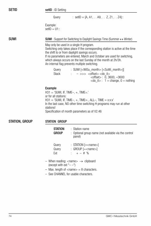
74 GMC-I Messtechnik GmbH
SETID setID : ID Setting
Example:setID = U1::
SUWI SUWI : Support for Switching to Daylight Savings Time (Summer Winter)
May only be used in a single H program.Switching only takes place if the corresponding station is active at the time the shift to or from daylight savings occurs.If no parameters are entered, March and October are used for switching, which always occurs on the last Sunday of the month at 2h/3h.An internal flag prevents multiple switching.
ExampleH31 = ’SUWI, IF, TIME–, +, TIME=.’or for all stations:H31 = ’SUWI, IF, TIME–, +, TIME=., ALL–, TIME = x:x:x’In the last case, NO other time switching H programs may run at other stations!Specification of month parameters as of V2.46
STATION, GROUP STATION GROUP
– When reading: <name> clipboard (except with ext "– –")
– Max. length of <name> = 8 characters.– See CHANNEL for usable characters.
Query : setID = {A, A1, . . A9, . . Z, Z1, . . Z4}::
Query : SUWI [<WiSu_month> [<SuWi_month>]]Stack : – >>> <offset> <do_it>
<offset> : 0, 3600, –3600<do_it> : 1 = change, 0 = nothing
STATION : Station nameGROUP : Optional group name (not available via the control
panel)
Query : STATION [=<name>]Query : GROUP [=<name>]Ext : + – # %
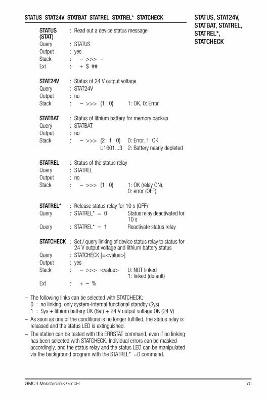
GMC-I Messtechnik GmbH 75
STATUS, STAT24V, STATBAT, STATREL, STATREL*, STATCHECK
STATUS STAT24V STATBAT STATREL STATREL* STATCHECK
– The following links can be selected with STATCHECK: 0 : no linking, only system-internal functional standby (Sys)1 : Sys + lithium battery OK (Bat) + 24 V output voltage OK (24 V)
– As soon as one of the conditions is no longer fulfilled, the status relay is released and the status LED is extinguished.
– The station can be tested with the ERRSTAT command, even if no linking has been selected with STATCHECK. Individual errors can be masked accordingly, and the status relay and the status LED can be manipulated via the background program with the STATREL* =0 command.
STATUS (STAT)
: Read out a device status message
Query : STATUSOutput : yesStack : – >>> –Ext : + $ ##
STAT24V : Status of 24 V output voltageQuery : STAT24VOutput : noStack : – >>> {1 | 0} 1: OK, 0: Error
STATBAT : Status of lithium battery for memory backupQuery : STATBATOutput : noStack : – >>> {2 | 1 | 0} 0: Error, 1: OK
U1601...3 2: Battery nearly depleted
STATREL : Status of the status relayQuery : STATRELOutput : noStack : – >>> {1 | 0} 1: OK (relay ON),
0: error (OFF)
STATREL* : Release status relay for 10 s (OFF)Query : STATREL* = 0 Status relay deactivated for
10 sQuery : STATREL* = 1 Reactivate status relay
STATCHECK : Set / query linking of device status relay to status for 24 V output voltage and lithium battery status
Query : STATCHECK [=<value>]Output : yesStack : – >>> <value> 0: NOT linked
1: linked (default)Ext : + – %
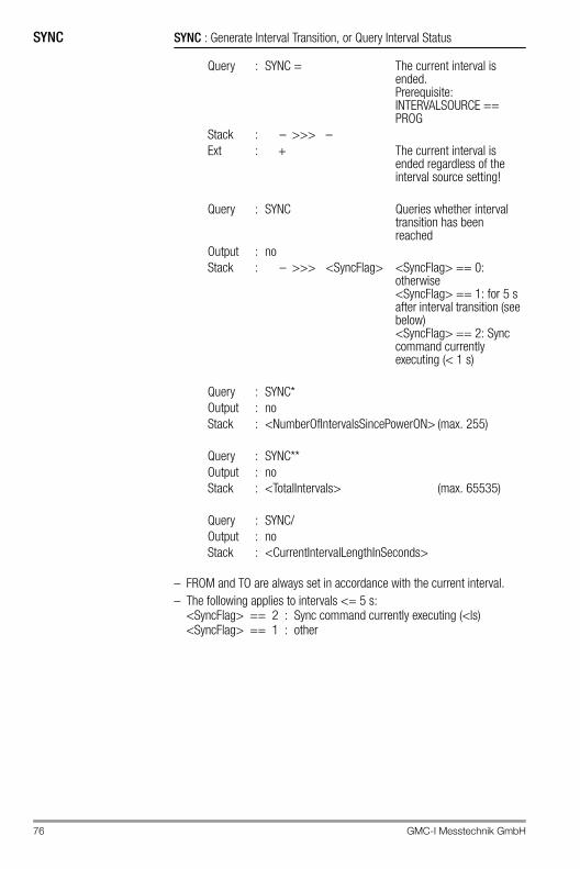
76 GMC-I Messtechnik GmbH
SYNC SYNC : Generate Interval Transition, or Query Interval Status
– FROM and TO are always set in accordance with the current interval.– The following applies to intervals <= 5 s:
<SyncFlag> == 2 : Sync command currently executing (<ls) <SyncFlag> == 1 : other
Query : SYNC = The current interval is ended.Prerequisite: INTERVALSOURCE == PROG
Stack : – >>> –Ext : + The current interval is
ended regardless of the interval source setting!
Query : SYNC Queries whether interval transition has been reached
Output : noStack : – >>> <SyncFlag> <SyncFlag> == 0:
otherwise<SyncFlag> == 1: for 5 s after interval transition (see below)<SyncFlag> == 2: Sync command currently executing (< 1 s)
Query : SYNC*Output : noStack : <NumberOfIntervalsSincePowerON> (max. 255)
Query : SYNC**Output : noStack : <TotalIntervals> (max. 65535)
Query : SYNC/Output : noStack : <CurrentIntervalLengthInSeconds>
GMC-I Messtechnik GmbH 77
System FunctionsSysRESET SysTEST SysSN SysDC SysOPEN LANGUAGE SysID
– SYSTEST <number> checks the ECS LAN. 64 user data bytes are exchanged <number> times for test purposes with the referenced station (32 bytes to and 32 bytes from). If there is no other ECS LAN traffic, the measured baud rate is equal to transmission line quality.
Example<A> B: systest 1006400 bytes are exchanged between stations A: and B:, required time and the baud rate are subsequently read out.IMPORTANT: Each additional ECS LAN segment between the two devices reduces the baud rate (required time * n). RECOMMENDED VALUE (n = 1, 62K5 bd):
U1600 : 2000 . . 2500 bytes/sU1610/15 : 2500 . . 3000 bytes/sU1601 : 3000 . . 3500 bytes/s
– <openlevel> : 0 : disabled, >=1 : enabled– Enabling must be performed with SYSOPEN in order to calibrate analog
channels, otherwise the following error message appears: “access denied”.
– Enabling is active for a period of 4 minutes after SYSOPEN, and is extended for an additional 4 minutes each time a command is entered within this period of time.
– If a device has been enabled, it is enabled at all ports (COM1, COM2, . . .).
SYSOPEN functions throughout the entire ECS LAN, but only locally for the U1600/10/15 (AA:station); SYSOPEN–, SYSOPEN? are not available with the U1600/10/15.
SysRESET : Executes CPU reset(similar to PowerOn reset)
Query : sysRESET = 0
SysTEST : Tests several system functions and prints results.Query : sysTEST [<number<] [=0]Stack : – >>> ESCC2[L] ESCC2[R]Ext : – . &
SysSN : Query device serial numberSysDC : Query calibration date codeQuery : SYSSNStack : – >>> –SysID : Query summator typeSysOPEN : Enable access to specific internal functions:Query : SYSOPEN SYSOPEN– SYSOPEN?Function : enable disable –Output : no no noStack : – >>> – – >>> – – >>> <openLevel>
78 GMC-I Messtechnik GmbH
– The availability of languages depends upon the firmware revision level.– The ECL interpreter is bilingual only (German / English).
German and English commands can be mixed as desired, however, the output language is determined as follows: German where <country> == 1, English where <country> >= 2
– Only the first letter of the <country> must be entered, and no differentiation is made between upper and lower case letters.
– Ext. ‘|‘ pushes the current language index to the stack during reading.– LISTLANGUAGE generates a list of all available languages (U1600: n.a.)– Select German: LANGUAGE = German or LANGUAGE = 1– Select English: LANGUAGE = English or LANGUAGE = 2
DAYBEG DAYBEG : Variable Beginning of Day (can only be set via terminal or ECSwin)
Default setting = 00:00:00This setting affects all past and future day beginnings and may not be altered dynamically!
TARIFF TARIFF : Query or Set Current Tariff
<tariff> = {1 | 2}; ’1’: Tariff 1, ’2’: Tariff 2– With ext ’*’, <tariff> = {0 | 1}; 0’: Tariff 1, ’1’: Tariff 2
Examples (with ext ‘*‘):1. Tariff T2 applies between 22h00 and 6h00, and otherwise T1:
H 10= ‘hh,6,<,hh,22,>, | ,tariff* =.‘ 2. Tariff T2 applies on weekends (Saturday and Sunday):
H10 10= ‘wday,6,>=,tariff* =.‘
LANGUAGE : Sets the user interface language at the control panel.
Query : LANGUAGE [=<country>]Output : yesClipboard : yesStack : – >>> –Ext : + – # . $ %
<country> : 1 | D | GERMAN | G | GERMANY: 2 | E | ENGLISH: 3 | S | SPANISH | ES | ESPANGNOLE: 4 | I | ITALIAN: 5 | F | FRENCH
Query : DAYBEG [=<time_of_dayBegin>]Stack : – >>> <time_of_dayBegin>Ext : – . # &
Query : TARIFF [=<tariff>]Output : yesStack : – >>> <tariff> (when reading)Ext : + – * %
GMC-I Messtechnik GmbH 79
KEYKEY (TT) : Transfers keystrokes executed at the control panel.
<keySequence> elements, maximum length is 20 elements:
ExampleKEY x++++4x sets the control panel to the default display, 4* ’+’ moves to channel 5. 4 stands for F4, i.e. change to Pmom.
LOCKKB, LOCKKBMLOCKKB, LOCKKBM : Disable the Keyboard (or selected keys)
(U1601 as of V2.45, U1600: n.a.)
The entire keyboard, or selected keys only, can be disabled based upon a timeout, i.e. the disabling command is only valid for a specified period of time, after which enabling occurs for safety reasons. These commands are used primarily in H programs.
LOCKKB : Disable the Entire Keyboard
– If a key is pressed after disabling has been activated, the “KEYBOARD DISABLED” message appears briefly at the display.
Query : KEY <keySequence>Output : noneStack : – >>> –
1 . . 5 : F1 . . F5+ : scroll up– : scroll down< : scroll left> : scroll rightm : Menus : Setup (same as "press and hold menu key for 1 s")# : Enter! : ESCq : ESC-ESC (return to first level).
(U1600/10/15 n.a.)u : Shift (U1600 only, same as "press scroll up and down
keys simultaneously")l : Enter delete menu or similar functionx : Set to default status (normal display with Etot,
channel 1)
Query : LOCKKB [= <disable_duration>] <disable_duration>Output : yesStack : – >>> <remaining_disable_duration>
0 : Cancel disabling1 : 5 s disabling2...60: Disable duration in [s]
80 GMC-I Messtechnik GmbH
LOCKKBM : Selective Keyboard Disabling (with key mask) for 60 s
– Bit positions: (MSB) bit 31 .. bit 0 (LSB)– Bit value: 1 = key disabled, 0 = key enabled;
With <meld>: 1 = “KEYBOARD DISABLED” message appears, 0 = no message
– Masks can be understandably formulated using binary notation (“0b” prefix).
ExampleDisable UP + DOWN keys, message if these keys are activated:LOCKKBM = 0b1000000001100000 or LOCKKBM = 32864
Trigonometric Functions
SQRT SIN COS ASIN ACOS DEG RAD EXP LOG : Mathematical Functions
Query : LOCKKBM [= <disabling_mask>]Output : yesStack : – >>> <disabling_mask>
<disabling-mask> : Key Bit Key Bit Key Bit
F1 0 LEFTS 8 SETUP 16F2 1 ENTER 9 DEL 17F3 2 MENU 10 X 18F4 3 ESC 11 ESCESC 19F5 4 AUTO 12 –UP 5 MAN 13 –DOWN 6 LR 14 –RIGHT 7 <meld> 15 –
Stack:SQRT : x >>> square root (x)SIN : x >>> sine (x) based upon radian measureCOS : x >>> cos (x)ASIN : x >>> asin (x) opposite of SINEACOS : x >>> acos (x)DEG : x >>> ((x/pi)*180) convert radian measure to
degreesRAD : x >>> ((x/180)*pi) convert degrees to radian
measureEXP : x >>> (e to the power of x)LOG : x >>> LOGe (x)
PI : – >>> pi 3.141592653589793
GMC-I Messtechnik GmbH 81
TX1, TX2TX1 TX2
– The string may have a length of up to 127 characters.– Send command output (uses the clipboard): ETOT– – 1, TX2 $– The string may be sent to other stations as well.
UTCUTC Using Universal Time UTC (Greenwich Meridian Time ) from V2.48
The UTC time processing system allows for the allocation of time stamps for all time relevant data independent of daylight savings time or standard time. This enables higher-level PC-based evaluation software to read in all time stamps on GMT (Greenwich Meridian Time) basis, if required. For example, if an event occurred in Germany at 5:14 p.m. in July (daylight savings time), querying the UTC time stamp would prompt the evaluation software to read out 3:14 p.m. as local time is based on the GMT + 2 time zone (due to day-light savings time). However, if the evaluation software uses the commands previously in use for reading in data per time stamp, the device continues to supply time stamps which are based on local time. Converting the devices to UTC processing is completely transparent as far as external operation is con-cerned, except that the extension “I” (vertical line) must be added to the commands which read or write GMT-based time information.
– ATTENTION: UTC time processing must always be activated for the entire system, i.e. all LAN devices must use the same UTC parameters. Excep-tion: The device-internal time (RTC) of older devices, the firmware of which does not support UTC time processing, must be adjusted to UTC time.
TX1 : Send a string to COM1(with COM2-MIX to COM2)
Query : TX1 <character_string>
TX2 : Send a string to COM2Query : TX2 <character_string>
utcTZ : Time zone Query : utcTZ = <timezone>]Setting : –12..0..+12 hutcDST : Use conversion to daylight savings time
(DST = Daylight Savings Time)Query : utcTZ = <use_dst>Setting : 0=no, 1=yesutcSH : HemisphereQuery : utcTZ = <south_hemisphere>Setting : 0:north, 1:southutcUF : UsedFlagRead status : 0=UTC on, 1=UTC offutcSF : Daylight savings flagRead status : 0=standard, 1=daylight savings (+1h)utcETZ : Actual time zone, taken into accountRead status : Conversion to daylight savings time: –12..+13h
82 GMC-I Messtechnik GmbH
– UTC processing is active (utcUF supplies 1) if any of parameters utcTZ, utcDST or utcSH is not 0.
– After activating UTC time, system time is shifted by the actually valid time difference and must be corrected once. The integrated real-time clock (RTC) uses UTC time instead of local time in UTC operating mode.
– Every ECL command containing time information can be modified with extension “I” for UTC time query. Examples:
TIME prints local timeTIME| prints UTC time
The subsequent time setting commands are identical(with: utcDST=1, utcTZ=1, utcSH=0 during daylight savings time):
TIME = 14:00 sets device-internal time at local timeTIME|= 12:00 sets at UTC time (local - 2h)
– Automatic conversion from daylight savings to standard time and vice versa takes place in the night from Saturday to Sunday at the last week end in March or October (the indicated times are local times):
– The previous H program for conversion to daylight savings time or stan-dard time with command SOWI may be deleted when UTC time is in use. Keeping this command is no problem either since command SOWI sup-plies 0 in UTC mode (SOWI Stack: - >>> 0 0).
VER VER : Read Out Current Software Version
LVER LVER : Read out current ECS LAN version for determining scope of ECL commands available at the addressed ECS LAN user (as of Dec. 2001)
– Example of '|' ext., which simply reverses the stack order: Only code as of LAN version 2 is to be executed, and it is unknown whether or not the firmware recognizes the LVER command:
VER@|-,dr,2,>=,if, .... : execute ... only as of LV 2 VER@|-,dr, ! : stack output: LV or 0
Time of conversion with utcDST=1 utcSH=0 utcSH=1March, last Sunday at 2:00 a.m. +1h —March, last Sunday at 3:00 a.m. — –1hOctober, last Sunday at 2:00 a.m. — +1hOctober, last Sunday at 3:00 a.m. –1h —
Query : VEROutput : yesStack : – >>> <versionNumber>Ext : + – . $ # %
Query : LVERVER@ (alternative command form – always available)
Output : yesStack : – >>> <LAN_code> <LAN_version_number>Ext : + – . $ # % |
GMC-I Messtechnik GmbH 83
FROM TO DURATIONFROM TO DURATION.
The two variables FROM and TO are set as soon as a corresponding command with extension / or ^ is used. The period of time which elapses between FROM ... TO can be set in seconds with DUR.
Date/Time <timeNumber> Notes concerning the use of extensions / and ^
Modification of output defined by / or / / or / / /(/ always precedes ^)
FROM TO : Query time-number of last output "with time"DURATION (DUR)
: Duration of time FROM ... TO in seconds
Query : FROMOutput : noStack : – >>> <timeNumber> <timeNumber>: second
count as of 1.1.1990
/ : ^ : Output with time "to"/ / : ^ ^ : Output with time "from ––to"/ / / : ^ ^ ^ : Output with time "from"/ / / / : ^ ^ ^ ^ : Suppress output (TO and FROM are
nevertheless set)
/ ^ : Output time/date instead of date/time31.12.93;17:33:56
/ ^ ^ : Output date/time, date in DBase format yyyymmdd19931231;17:33:56
/ ^ ^ ^ : Output time/date, date in DBase format yyyymmdd17:33:56;19931231
/ ^ ^ ^ ^ : Date/time delimiter ’;’ ’ ’ (suitable for MS-EXCEL) 31.12.93 17:33:56
/ ^ ^ ^ ^ ^ : Time/date delimiter ’;’ ’ ’ (suitable for MS-EXCEL) 17:33:56 31.12.93
84 GMC-I Messtechnik GmbH
TIME, DATE TIME DATE : Set or Query System Time and Date
– <timeString> format: 12:36:00 or 2h15– <dateString> format: 17.03.92 or 26.02 [see DATEFORMAT regarding
date formats]– <timeNumber> is the second count as of 1.1.1990.– TIME / / always displays time and date, DATE / / always displays date and
time.TIME / / = 30.11 11h can be used to set time/date or date/time together.
– See TIMECOMPARISON for time comparisons. See SUWI regarding daylight savings time.
– TIME* pushes (<timeNumber>.<secondsFraction>)See DCF77 for synchronization to radio controlled clock.
– Time measurements: [command doublet TM / TMD (== ZM / ZMD)]’tm, <Block>, tmd, !’ displays length of <Block>, stack must conform! ’a = t, <Block>, a, tmd, !’ displays length of <Block>, stack irrelevant.Time indicated in seconds with 1/100 s.
– Ext. ‘^‘ changes the order of Time/Date and/or selects a database-compatible date format. DATE/^^ 19980427 [see also FROM]
– Ext. ’_’ : Operating hours counter is used instead of real-time. See TIME COMPARISONS.
NoteOnly time queries made with the commands TIME or DATE result in a read-out of actual time or operating hours counter time from the addressed stations. All other time commands make reference to the station at which the command was physically executed (as if ID AA: were always placed in front of the command).
TM / TMD: Time Measurements‘tm, <Block> , tmd,!‘ reads out duration of <Block>,
stack must conform!’a =t, <Block> ,a,tmd,!‘reads out duration of <Block>,
stack irrelevant.Time indicated in seconds with 1/100 s.
Set Query Display timeQuery : TIME =
<time string<TIME TIME .
Output : no yes : hh:mm:ss yes : hh:mm:ssStack : – >>> – – >>> <timeNo.> <timeNo.> >>> –Ext : + – * . / ^ _ %
GMC-I Messtechnik GmbH 85
System Time Comparisons
System Time Comparisons
– Since the entry for the point in time may also include the place holder "x", an entire time range can be used (see example).
– If IF <timePoint> is used in H programs, the condition is only fulfilled once per second during the valid time range.
– If cycle time for the H programs is greater than 1 second, a special process assures that points in time are not omitted.
– If system time has been synchronized (e.g. by means of the DCF77 radio controlled clock), time deviations (+/–1 ... 3 s) cannot be avoided. Setting system time forward is covered by the above mentioned process, but setting system time back does not allow for the re-recognition of points in time if deviation is less than -3 s (U1600: n.a.).
Exampleh10 = ’IF 17.3 xh10.xx, rel 1 = 1, else, rel 1 = 0’Relay 1 will be activated for one minute at every full hour + 10 minutes on the 17th of March.
Operating Hours Counter Time(see also chapter 1.7 „Tool Box (Examples of use)“ and acquiring operat-ing data here)– Extension ‘_‘ with TIME, TM_, TMD_, SYNC_/, a=t_ etc. uses
operating hours counter time (zero after master reset) instead of real time.– Important for time duration measurement (for example when switching
back and forth between daylight savings and standard time).Observe station references for time queries, see TIME!
Query : IF <date_or_timeString> [<timeString>](IFF also possible)
Stack : – >>> –
86 GMC-I Messtechnik GmbH
Time Counter Time Counter
– The HTD command is used exclusively in background H programs:
The time difference since the last HTD execution is pushed to the stack (separately for every H program). Times longer than 60 s 0 s.– HTD* executes EXIT if result == 0:
HTD*, ... is thus identical to HTD,DUP,0,==,IF,EXIT,ELSE,...Example of time counting (in seconds) with channels 10 ... 15, as long as STARTSTOP for the respective channel is = 1:H 10 = ’HTD, DELTA 10..15=.’or in hours:H 10 = ’HTD, 3600,/, DELTA 10..15=.’Connect input 10 to STARTSTOP 10:H 11 = ’IN– 10,STSP 10=.’
MCONST, URAT, IRAT, PULSE, EDGE,ONOFF, STARTSTOP, CFIX, CFACTOR
MCONST Urat Irat PULSE EDGE ONOFF STARTSTOP (STSP)CFIX CFACTOR : Channel Specific Parameters
Query : HTDStack : – >>> <TimeDeltaInSeconds>
MCONST : Meter constant <real>Urat : Voltage transformation ratio <real>Irat : Current transformation ratio <real>PULSE : Pulse duration in milliseconds (10 ... 2550 ==
0, 01 s ... 2.55 s)EDGE : active time edge or tariff assignment (binary input):
1: _ _ ––change: 0 V >>> 24 V (+) or 24 V Tariff 20: – – _ _ change: 24 V >>> 0 V (–) or 24 V Tariff 1
ONOFF : Switch channel ON/OFF: 1: ON 0: OFFSignificance for summator display: Displaying/masking out selected channels.Significance for querying via interface:only activated channels are read out.Controlling selection * when channels are listed: Example: Etot* supplies Etot of all activated channels
STARTSTOP : Control pulse counting at the channel:1: START 0: STOP
CFIX : Fixed decimal places for output (0: 0 1: 0.0 2: 0.00 or 3: 0.000)
CFACTOR : General factor for energy and power (U1600: n.a.)
Query : MCONST <enumeration> [=<assignment>]Stack : – >>> value (when reading)Ext : + – . # %
87 GMC-I Messtechnik GmbH
2.3 Command Equivalents
German – English Command Equivalents
The ECS operating system allows for entry of almost all ECL commands in either English or German, regardless of the selected user interface language. The online help function also accepts search terms in both languages.GMC-I Messtechnik GmbHDesignations for the following ECL commands have both German and English names:
German EnglishAEINH AUNITAUFZ ENUMBIS TODATUM DATEDATUMFORMAT DATEFORMATDAUER DURATIO (DUR)EEINH EUNITEGES ... ETOT ...EINAUS ONOFFEMAXTAG, ... YEAR EMAXDAY, ... YEARERRKAN ERRCHANFLANKE EDGEINTERVALL INTERVALINTERVALLQUELLE INTERVALSOURCEJAHR YEARKANAL CHANNEL (CHAN)KANALFIX CHANNELFIX (CFIX)KENN IDKOSTFAK1 KOSTFAK2 COSTFAC1 COSTFAC2LOESCHKANAL ERACHANLOESCHLISTE ERALISLONKANAL LONCHANNELPASSWORT PASSWORDPEGEL LEVELPEINH PUNITPFAKTOR PFACTORPMAXTAG, ... JAHR PMAXDAY, ... YEARPULS PULSERELAIS RELAYRELAISMODE RELAYMODERELAISNAME RELAYNAMESETKENN SETIDSPRACHE LANGUAGETAG DAYTARIF TARIFFTARIFQUELLE TARIFFSOURCETASTE KEYTEINH TUNITVON FROMWTAG WDAYZEIT TIMEZKONST MCONST

88 GMC-I Messtechnik GmbH
GMC-I Messtechnik GmbH 89
AA Registers ............................................................25ALL .........................................................................24ALL NEXTA .............................................................24AnaFACTOR ...........................................................28Analog Processing (inputs, outputs) .....................26AnaMODE ..............................................................26AnaMODSEL ..........................................................26AnaOFFSET ............................................................28Arithmetic Operators .............................................24AUNIT .....................................................................36
BBUS ........................................................................30BUSL ......................................................................30BUSR ......................................................................30
CCFACTOR ...............................................................86CFIX ........................................................................86CHAIN .....................................................................31CHANNEL ...............................................................51CMODE ..................................................................52Command Parameters ..........................................19COSTFAC1 .............................................................53COSTFAC2 .............................................................53COSTT1 ..................................................................36COSTT1T2 .............................................................36COSTT2 ..................................................................36
DDATE ......................................................................84DATEFORMAT ........................................................32DAY ........................................................................46DAYBEG .................................................................78DELIMITER .............................................................32DELTA ....................................................................33DevKEY ...................................................................33DIR ..........................................................................34DIRN .......................................................................34DIRS .......................................................................34DISPLAY .................................................................34DO ..........................................................................68
DOWHILE ............................................................... 68DROP ..................................................................... 35DUP ....................................................................... 35DURATION ............................................................. 83DVIRT .................................................................... 35DVSUM .................................................................. 35
EECL SYNTAX ......................................................... 17EDAY ..................................................................... 42EDGE ..................................................................... 86EINT ....................................................................... 38EMAX ..................................................................... 42EMON .................................................................... 42ENUM .................................................................... 29ENUM@ ................................................................. 30ERACHANNEL ....................................................... 53ERALIST ................................................................. 53ERR ........................................................................ 38ERRCHAN .............................................................. 38ERRCHANLIST ....................................................... 38ERRNR ................................................................... 38ERRSTAT ............................................................... 38ERRSTATLIST ........................................................ 38ETOT ...................................................................... 36ETOTT1 ................................................................. 36ETOTT1T2 ............................................................. 36ETOTT2 ................................................................. 36EUNIT ..................................................................... 36EXIT ....................................................................... 43Extensions ............................................................. 18EYEAR .................................................................... 42
FFDIR ....................................................................... 43FINDER .................................................................. 20FLIST ..................................................................... 43FORI NEXTI ............................................................ 44FORJ NEXTJ .......................................................... 44FORK NEXTK ......................................................... 44FORMAT ................................................................ 45FREAD ................................................................... 43FROM TO .............................................................. 83
3 Parameter Search Terms
Command Page Command Page
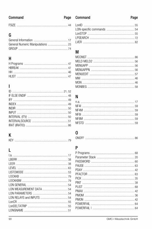
90 GMC-I Messtechnik GmbH
FSIZE ..................................................................... 44
GGeneral Information .............................................. 17General Numeric Manipulations ........................... 23GROUP ................................................................... 74
HH Programs ........................................................... 47HBREAK ................................................................. 47HH .......................................................................... 46HLIST ..................................................................... 47
IID ..................................................................... 21, 52IF ELSE ENDIF ....................................................... 48IFF .......................................................................... 49INDEX ..................................................................... 49INDIR ...................................................................... 50INPUT ..................................................................... 50INTERVAL (ITV) ...................................................... 50INTERVALSOURCE ................................................ 51IRAT (IRATIO) ......................................................... 86
KKEY ........................................................................ 79
Ll.a. .......................................................................... 17LBERR .................................................................... 38LEER ...................................................................... 38LEVEL .................................................................... 63LISTCMODE ........................................................... 53LOCKKB ................................................................. 79LOCKKBM .............................................................. 79LON GENERAL ....................................................... 54LON MEASUREMENT DATA .................................. 54LON PARAMETERS ............................................... 54LON RELAYS and INPUTS ..................................... 54LonCR .................................................................... 55LonDELTATRIP ...................................................... 55LONGNAME ........................................................... 51
LonID ..................................................................... 55LON-specific commands ...................................... 54LonSTOP ................................................................ 55LPSEARCH ............................................................. 72LVER ...................................................................... 82
MMCONST ................................................................ 86MELD MELD2 ........................................................ 56MENUAPP .............................................................. 56MENUAPPN ........................................................... 56MENUEDIT ............................................................. 57MM ........................................................................ 46MON ....................................................................... 46MONBEG ................................................................ 58
Nn.a. ......................................................................... 17NF4I ....................................................................... 59NF4M ..................................................................... 59NF8I ....................................................................... 59NF8M ..................................................................... 59NFSTD ................................................................... 59
OONOFF ................................................................... 86
PP Programs ............................................................ 68Parameter Stack ................................................... 20PASSWORD ........................................................... 60PAUSE .................................................................... 63PDAY ...................................................................... 42PFACTOR ............................................................... 63PICK ....................................................................... 35PINT ....................................................................... 38PLIST ..................................................................... 68PMAX ..................................................................... 42PMOM .................................................................... 36PMON .................................................................... 42POWERFAIL ........................................................... 64POWERFAIL | ......................................................... 64
Command Page Command Page
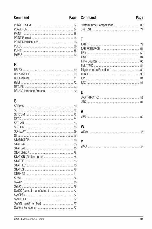
GMC-I Messtechnik GmbH 91
POWERFAIL@ ........................................................64POWERON ..............................................................64PRINT .....................................................................65PRINT Format ........................................................65PRINT Modifications ..............................................66PULSE ....................................................................86PUNIT .....................................................................36PYEAR ....................................................................42
RRELAY ....................................................................69RELAYMODE ..........................................................69RELAYNAME ..........................................................71REM ........................................................................72RETURN ..................................................................43RS 232 Interface Protocol .....................................22
SS0Pxxxx ..................................................................70SET... ......................................................................72SETCOM .................................................................73SETID ......................................................................74SETLAN ..................................................................73SETLON ..................................................................73SORELAY ................................................................69SS ...........................................................................46STARTSTOP ...........................................................86STAT24V ................................................................75STATBAT ................................................................75STATCHECK ...........................................................75STATION (Station name) ........................................74STATREL ................................................................75STATREL* ...............................................................75STATUS ..................................................................75STRINGS ................................................................21SUWI ......................................................................74SWAP .....................................................................35SYNC ......................................................................76SysDC (date of manufacture) ................................77SysOPEN ................................................................77SysRESET ...............................................................77SysSN (serial number) ...........................................77System Functions ..................................................77
System Time Comparisons .................................. 85SysTEST ................................................................ 77
TTARIFF ................................................................... 78TARIFFSOURCE ..................................................... 51TFIX ....................................................................... 53TIME ...................................................................... 84Time Counter ........................................................ 86TM / TMD .............................................................. 84Trigonometric Functions ....................................... 80TUNIT ..................................................................... 36TX1 ........................................................................ 81TX2 ........................................................................ 81
UURAT (URATIO) ...................................................... 86UTC ........................................................................ 81
VVER ........................................................................ 82
WWDAY .................................................................... 46
YYEAR ...................................................................... 46
Command Page Command Page

Edited in Germany • Subject to change without notice • A pdf version is available on the Internet
GMC-I Messtechnik GmbHSüdwestpark 1590449 Nürnberg • Germany
Phone +49 911 8602-111Fax +49 911 8602-777E-Mail [email protected]
4 Product Support Industrial DivisionIf required please contact:
GMC-I Messtechnik GmbHProduct Support Hotline – Industrial Division Phone +49 911 8602-500Fax +49 911 8602-340E-mail [email protected]