Embed Size (px)
DESCRIPTION
ecg_001
Citation preview
Mobile Healthcare on AndroidDevices
Sacha GilgenBasel, Switzerland
Student ID: 02-052-942
Supervisor: Andrei Vancea, Guilherme MachadoDate of Submission: November 2, 2010
University of ZurichDepartment of Informatics (IFI)Binzmühlestrasse 14, CH-8050 Zürich, Switzerland
DIP
LOM
AT
HE
SIS
–C
omm
unic
atio
nS
yste
ms
Gro
up,P
rof.
Dr.
Bur
khar
dS
tille
r
Diploma ThesisCommunication Systems Group (CSG)Department of Informatics (IFI)University of ZurichBinzmühlestrasse 14, CH-8050 Zurich, SwitzerlandURL: http://www.csg.uzh.ch/
Zusammenfassung
Die Fortschritte der jungsten Zeit in den Bereichen kabelloser Sensoren und mobiler Kom-munikation, ermoglichen neue Formen der Anwendung in der Gesundheitspflege. Insbe-sondere die Verfugbarkeit von kleinen, leichten und sehr sparsamen Sensoren, bieten neueMoglichkeiten einer kontinuierlichen Uberwachung menschlicher, biomedizinischer Datenund ermoglichen somit die Fruherkennung eines Krankheitspotentials.
Diese Bachelorarbeit stellt einen Prototypen der mobilen Gesundheitspflege vor, der beab-sichtigt, EKG-Daten von Patienten zu uberwachen. Das System besteht aus drei Elemen-ten: einem tragbaren Sensor, der EKG-Daten am Patienten aufzeichnet; einem Mobiltele-fon, das als Schnittstelle fungiert, indem es die vom Sensor erhaltenen Daten ubermittelt;und schliesslich einem Server, der uber ein Anzeigemodul zur graphischen Darstellungubermittelter EKG-Daten verfugt. Basierend auf das angezeigte EKG, sind Arzte in derLage einige grundlegende, medizinische Einschatzungen fur ihre Patienten zu machen.
i

ii
Abstract
Recent technological advances in wireless sensors and mobile communication enable newtypes of healthcare systems. Especially the availability of small, lightweight and ultra-lowpower sensors gives new possibilities for a continuously monitoring of human biomedicaldata and therefore allows an early detection of potential illness.
This bachelor thesis presents a prototype mobile healthcare system intended to monitorECG data from a patient. The system consists of three parts: a wearable sensor thatrecords ECG data on a patient, a mobile phone that acts as a gateway by forwardingthe data received from the sensor and finally a server containing a visualization moduleto graphically display the recorded ECG data. Based on the displayed ECG, doctors areable to make some basic medical diagnostics for their patients.
iii

iv
Acknowledgments
First of all, I would like to express my gratitude to Professor Burkhard Stiller for givingme the opportunity to write this bachelor thesis.
Furthermore, special thanks go to my supervisors Andrei Vancea and Guilherme Machadofor the time and effort they spent and for their precious advices.
Finally, I would like to thank my mother and father for their assistance, encouragementand love during my studies.
v

vi
Contents
Zusammenfassung i
Abstract iii
Acknowledgments v
1 Introduction 1
1.1 Motivation . . . . . . . . . . . . . . . . . . . . . . . . . . . . . . . . . . . . 1
1.2 Description of Work . . . . . . . . . . . . . . . . . . . . . . . . . . . . . . 2
1.3 Thesis Outline . . . . . . . . . . . . . . . . . . . . . . . . . . . . . . . . . . 2
2 Related Work 5
2.1 Electrocardiography . . . . . . . . . . . . . . . . . . . . . . . . . . . . . . 5
2.1.1 The Activity of the Heart . . . . . . . . . . . . . . . . . . . . . . . 6
2.1.2 3-Lead Electrocardiography . . . . . . . . . . . . . . . . . . . . . . 7
2.1.3 Interpretation of an Electrocardiogram . . . . . . . . . . . . . . . . 8
2.2 Shimmer Sensor Platform . . . . . . . . . . . . . . . . . . . . . . . . . . . 10
2.2.1 Shimmer Key Principles . . . . . . . . . . . . . . . . . . . . . . . . 10
2.2.2 Shimmer Platform Design . . . . . . . . . . . . . . . . . . . . . . . 11
2.2.3 Shimmer Key Features . . . . . . . . . . . . . . . . . . . . . . . . . 12
2.3 Google Android . . . . . . . . . . . . . . . . . . . . . . . . . . . . . . . . . 13
2.3.1 Android Architecture . . . . . . . . . . . . . . . . . . . . . . . . . . 13
2.3.2 Android Components . . . . . . . . . . . . . . . . . . . . . . . . . . 15
vii
viii CONTENTS
2.4 Ruby on Rails Web Framework . . . . . . . . . . . . . . . . . . . . . . . . 17
2.4.1 Ruby on Rails Architecture . . . . . . . . . . . . . . . . . . . . . . 17
2.4.2 Ruby on Rails Components . . . . . . . . . . . . . . . . . . . . . . 19
3 Design 21
3.1 Requirements . . . . . . . . . . . . . . . . . . . . . . . . . . . . . . . . . . 21
3.1.1 The Sensor Component . . . . . . . . . . . . . . . . . . . . . . . . . 22
3.1.2 The Mobile Component . . . . . . . . . . . . . . . . . . . . . . . . 23
3.1.3 The Server Component . . . . . . . . . . . . . . . . . . . . . . . . . 24
3.2 Architecture . . . . . . . . . . . . . . . . . . . . . . . . . . . . . . . . . . . 26
3.2.1 The Sensor Component . . . . . . . . . . . . . . . . . . . . . . . . . 26
3.2.2 The Mobile Component . . . . . . . . . . . . . . . . . . . . . . . . 27
3.2.3 The Server Component: . . . . . . . . . . . . . . . . . . . . . . . . 32
4 Implementation 39
4.1 Mobile Application . . . . . . . . . . . . . . . . . . . . . . . . . . . . . . . 39
4.1.1 Graphical User Interface . . . . . . . . . . . . . . . . . . . . . . . . 39
4.1.2 The Bluetooth Service Component . . . . . . . . . . . . . . . . . . 46
4.1.3 The Network Service Component . . . . . . . . . . . . . . . . . . . 52
4.2 Server Application . . . . . . . . . . . . . . . . . . . . . . . . . . . . . . . 52
4.2.1 Storage of ECG data . . . . . . . . . . . . . . . . . . . . . . . . . . 53
4.2.2 Vizualization of ECG data . . . . . . . . . . . . . . . . . . . . . . . 54
5 Future Work 57
6 Summary and Conclusions 61
Bibliography 63
Abbreviations 67
List of Figures 67
CONTENTS ix
List of Tables 70
A Installation Guidelines 73
A.1 Mobile Application . . . . . . . . . . . . . . . . . . . . . . . . . . . . . . . 73
A.2 Server Application . . . . . . . . . . . . . . . . . . . . . . . . . . . . . . . 74
B Contents of the CD 75
x CONTENTS
Chapter 1
Introduction
This bachelor thesis introduces a prototype mobile healthcare system, aimed to monitorECG data of a patient. First, the motivation of the work is presented, followed by a broaddescription of the mobile healthcare system developed.
1.1 Motivation
Recent technological advances in wearable sensor networks, integrated circuits and wirelesscommunication allow the design of lightweight, low power consuming sensors at low-cost[50]. Together with advances in mobile communication, new opportunities open up fordeveloping healthcare systems, which remotely monitor biomedical signals of patients.Especially the continous or even sporadic recording of biomedical signals, such as elec-trocardiography, are critical for the advancement of diagnosis as well as treatment of car-diovascular deseases [51]. For example the continous recording of the electrocardiogramby a wearable sensor could provide a realistic view on the heart condition of a patientduring normal daily routines. Current practices of monitoring the electrocardiogram athospital fail to generate such a realistic report of the heart rythm [51]. Further automatedanalysis of recorded biomedical data supporting doctors in their daily interpretation ofdata and allowing the development of warning systems are thinkable. This would bringseveral benefits, as to help decrease healthcare costs by increasing health observability,collaboration of doctors and doctor-to-patient efficiency [56]. Moreover, continious moni-toring will increase early detection of abnormal health conditions and diseases, providinga great potential to improve patients quality of life [55].This marks the beginning of anew trend for future healthcare systems which includes the evolution from disease centricto patient centric care, the delocalization of care from hospitals to home, and the focuson prevention rather than on reaction of already existing disorders [53] [54].
New generation of mobile phones will have an important impact for the developmentof such healthcare systems, as they seamlessly intergrate a wide variety of networks (3G,Bluetooth, wireless LAN and GSM) and thus provide the opportunity to transmit recordedbiomedical data to a central server in a hospital. The continuous monitoring of biomedical
1

2 CHAPTER 1. INTRODUCTION
data is then not bound to the home environment but could be extended outside of theseboundaries. Besides the broad communication capabilities, mobile phones support furtheropportunities like the monitoring of a patient’s location using GPS or the display ofbiomedical data. Especially the monitoring of location data could provide a contextto the recorded biomedical data. For example the location data could be used to gatherfurther information about the environment where the patient lives and thereby supportingthe analysis of patient health conditions.
The goal of this thesis is to design and implement a prototype mobile healthcare system,monitoring the electrocardiography signals of patients. Thereby the focus lies on sendingthe recorded data seamlessly from an wearable sensor over a mobile phone to a centralserver. Although the intended mobile healthcare system should only record electrocardio-graphy signals, it has to be designed to support the recording of further biomedical signals.The final developed mobile healthcare system should allow basic medical assessment ofpatients provided by doctors.
1.2 Description of Work
The objective of this work is to design and implement a prototype mobile healthcaresystem that uses Android mobile devices. The system should consist of three parts: Asensor application, a mobile application and a centralized server application.
The sensor application should record raw biomedical data in real time and transmit thisdata wirelessly to a connected Android mobile device.
The mobile application should then store the received biomedical data into a databaseand forward it to a centralized server after some initial processing. This way the mobiledevice acts as a gateway between the sensor and the server for the recorded data.
Finally the server stores the biomedical data into a database. Furthermore the servershould consist of two modules: a visualization module to graphically display the biomed-ical data and an analyzing module that implements a simple algorithm to perform basicassessments of patients.
While the prototype system shall only record and store ECG data, the architecture ofthe overall system should be implemented in a manner to be flexible enough in order tosupport various types of biomedical and environmental data.
1.3 Thesis Outline
This bachelor thesis is structured as follow: the next chapter forms the background for thefurther explanations by introducing electrocardiography and describing the technologiesused. The third chapter describes the design decisions and architecture of the prototypemobile healthcare system with respect to the defined requirements. This is followed bychapter four which describes the implementation of the previously defined design and
1.3. THESIS OUTLINE 3
architecture. In chapter five possible future work for the healcare system are presented.Finally the sixth chapter will conclude with a brief summary of the work done.
4 CHAPTER 1. INTRODUCTION
Chapter 2
Related Work
This chapter aims to present the fundamentals of electrocardiography before describingthe main technologies used later to implement the prototype healthcare system.
2.1 Electrocardiography
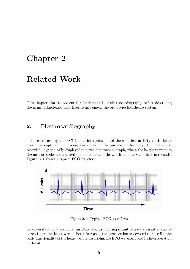
The electrocardiogram (ECG) is an interpretation of the electrical activity of the heartover time captured by placing electrodes on the surface of the body [1]. The signalrecorded, is graphically displayed in a two dimensional graph, where the height representsthe measured electrical activity in millivolts and the width the interval of time in seconds.Figure 2.1 shows a typical ECG waveform.
Figure 2.1: Typical ECG waveform
To understand how and what an ECG records, it is important to have a essential knowl-edge of how the heart works. For this reason the next section is devoted to describe thebasic functionality of the heart, before describing the ECG waveform and its interpretationin detail.
5
6 CHAPTER 2. RELATED WORK
2.1.1 The Activity of the Heart
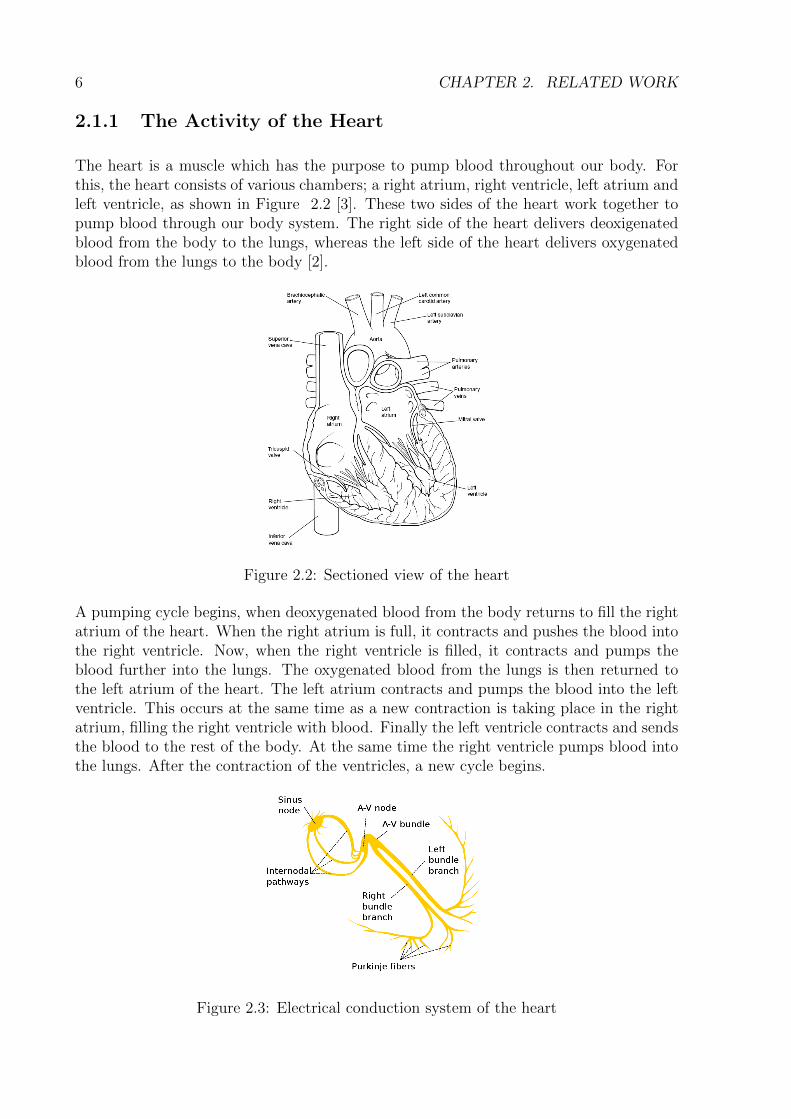
The heart is a muscle which has the purpose to pump blood throughout our body. Forthis, the heart consists of various chambers; a right atrium, right ventricle, left atrium andleft ventricle, as shown in Figure 2.2 [3]. These two sides of the heart work together topump blood through our body system. The right side of the heart delivers deoxigenatedblood from the body to the lungs, whereas the left side of the heart delivers oxygenatedblood from the lungs to the body [2].
Figure 2.2: Sectioned view of the heart
A pumping cycle begins, when deoxygenated blood from the body returns to fill the rightatrium of the heart. When the right atrium is full, it contracts and pushes the blood intothe right ventricle. Now, when the right ventricle is filled, it contracts and pumps theblood further into the lungs. The oxygenated blood from the lungs is then returned tothe left atrium of the heart. The left atrium contracts and pumps the blood into the leftventricle. This occurs at the same time as a new contraction is taking place in the rightatrium, filling the right ventricle with blood. Finally the left ventricle contracts and sendsthe blood to the rest of the body. At the same time the right ventricle pumps blood intothe lungs. After the contraction of the ventricles, a new cycle begins.
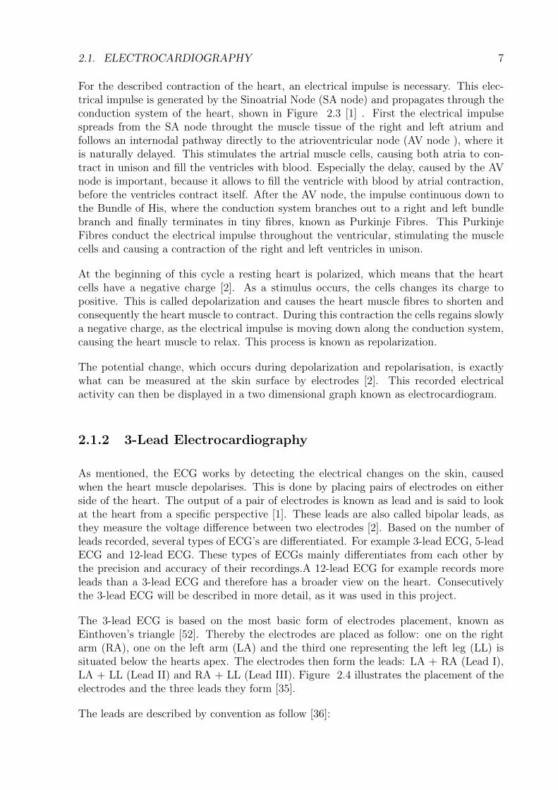
Figure 2.3: Electrical conduction system of the heart
2.1. ELECTROCARDIOGRAPHY 7
For the described contraction of the heart, an electrical impulse is necessary. This elec-trical impulse is generated by the Sinoatrial Node (SA node) and propagates through theconduction system of the heart, shown in Figure 2.3 [1] . First the electrical impulsespreads from the SA node throught the muscle tissue of the right and left atrium andfollows an internodal pathway directly to the atrioventricular node (AV node ), where itis naturally delayed. This stimulates the artrial muscle cells, causing both atria to con-tract in unison and fill the ventricles with blood. Especially the delay, caused by the AVnode is important, because it allows to fill the ventricle with blood by atrial contraction,before the ventricles contract itself. After the AV node, the impulse continuous down tothe Bundle of His, where the conduction system branches out to a right and left bundlebranch and finally terminates in tiny fibres, known as Purkinje Fibres. This PurkinjeFibres conduct the electrical impulse throughout the ventricular, stimulating the musclecells and causing a contraction of the right and left ventricles in unison.
At the beginning of this cycle a resting heart is polarized, which means that the heartcells have a negative charge [2]. As a stimulus occurs, the cells changes its charge topositive. This is called depolarization and causes the heart muscle fibres to shorten andconsequently the heart muscle to contract. During this contraction the cells regains slowlya negative charge, as the electrical impulse is moving down along the conduction system,causing the heart muscle to relax. This process is known as repolarization.
The potential change, which occurs during depolarization and repolarisation, is exactlywhat can be measured at the skin surface by electrodes [2]. This recorded electricalactivity can then be displayed in a two dimensional graph known as electrocardiogram.
2.1.2 3-Lead Electrocardiography
As mentioned, the ECG works by detecting the electrical changes on the skin, causedwhen the heart muscle depolarises. This is done by placing pairs of electrodes on eitherside of the heart. The output of a pair of electrodes is known as lead and is said to lookat the heart from a specific perspective [1]. These leads are also called bipolar leads, asthey measure the voltage difference between two electrodes [2]. Based on the number ofleads recorded, several types of ECG’s are differentiated. For example 3-lead ECG, 5-leadECG and 12-lead ECG. These types of ECGs mainly differentiates from each other bythe precision and accuracy of their recordings.A 12-lead ECG for example records moreleads than a 3-lead ECG and therefore has a broader view on the heart. Consecutivelythe 3-lead ECG will be described in more detail, as it was used in this project.
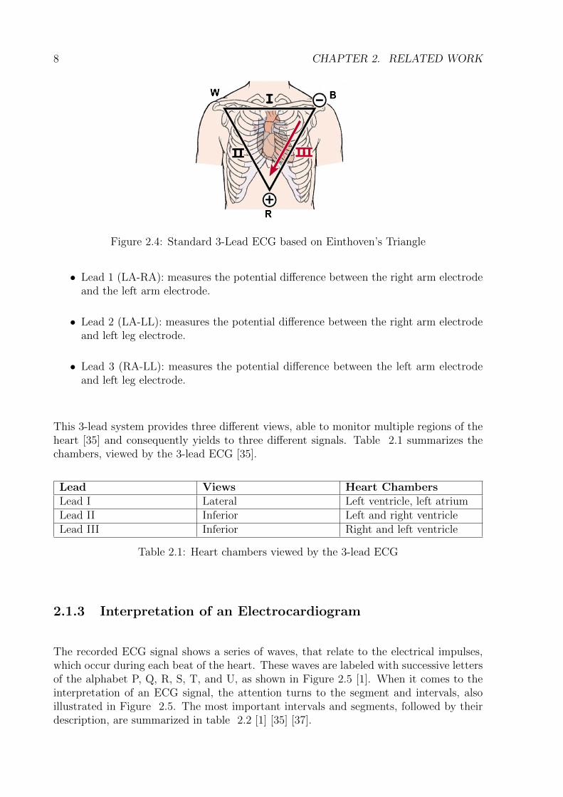
The 3-lead ECG is based on the most basic form of electrodes placement, known asEinthoven’s triangle [52]. Thereby the electrodes are placed as follow: one on the rightarm (RA), one on the left arm (LA) and the third one representing the left leg (LL) issituated below the hearts apex. The electrodes then form the leads: LA + RA (Lead I),LA + LL (Lead II) and RA + LL (Lead III). Figure 2.4 illustrates the placement of theelectrodes and the three leads they form [35].
The leads are described by convention as follow [36]:
8 CHAPTER 2. RELATED WORK
Figure 2.4: Standard 3-Lead ECG based on Einthoven’s Triangle
• Lead 1 (LA-RA): measures the potential difference between the right arm electrodeand the left arm electrode.
• Lead 2 (LA-LL): measures the potential difference between the right arm electrodeand left leg electrode.
• Lead 3 (RA-LL): measures the potential difference between the left arm electrodeand left leg electrode.
This 3-lead system provides three different views, able to monitor multiple regions of theheart [35] and consequently yields to three different signals. Table 2.1 summarizes thechambers, viewed by the 3-lead ECG [35].
Lead Views Heart ChambersLead I Lateral Left ventricle, left atriumLead II Inferior Left and right ventricleLead III Inferior Right and left ventricle
Table 2.1: Heart chambers viewed by the 3-lead ECG
2.1.3 Interpretation of an Electrocardiogram
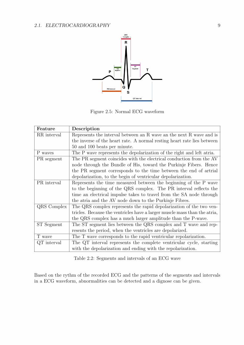
The recorded ECG signal shows a series of waves, that relate to the electrical impulses,which occur during each beat of the heart. These waves are labeled with successive lettersof the alphabet P, Q, R, S, T, and U, as shown in Figure 2.5 [1]. When it comes to theinterpretation of an ECG signal, the attention turns to the segment and intervals, alsoillustrated in Figure 2.5. The most important intervals and segments, followed by theirdescription, are summarized in table 2.2 [1] [35] [37].
2.1. ELECTROCARDIOGRAPHY 9
Figure 2.5: Normal ECG waveform
Feature DescriptionRR interval Represents the interval between an R wave an the next R wave and is
the inverse of the heart rate. A normal resting heart rate lies between50 and 100 beats per minute.
P waves The P wave represents the depolarization of the right and left atria.PR segment The PR segment coincides with the electrical conduction from the AV
node through the Bundle of His, toward the Purkinje Fibers. Hencethe PR segment corresponds to the time between the end of artrialdepolarization, to the begin of ventricular depolarization.
PR interval Represents the time measured between the beginning of the P waveto the beginning of the QRS complex. The PR interval reflects thetime an electrical impulse takes to travel from the SA node throughthe atria and the AV node down to the Purkinje Fibres.
QRS Complex The QRS complex represents the rapid depolarization of the two ven-tricles. Because the ventricles have a larger muscle mass than the atria,the QRS complex has a much larger amplitude than the P-wave.
ST Segment The ST segment lies between the QRS complex and T wave and rep-resents the period, when the ventricles are depolarized.
T wave The T wave corresponds to the rapid ventricular repolarization.QT interval The QT interval represents the complete ventricular cycle, starting
with the depolarization and ending with the repolarization.
Table 2.2: Segments and intervals of an ECG wave
Based on the rythm of the recorded ECG and the patterns of the segments and intervalsin a ECG waveform, abnormalities can be detected and a dignose can be given.
10 CHAPTER 2. RELATED WORK
2.2 Shimmer Sensor Platform
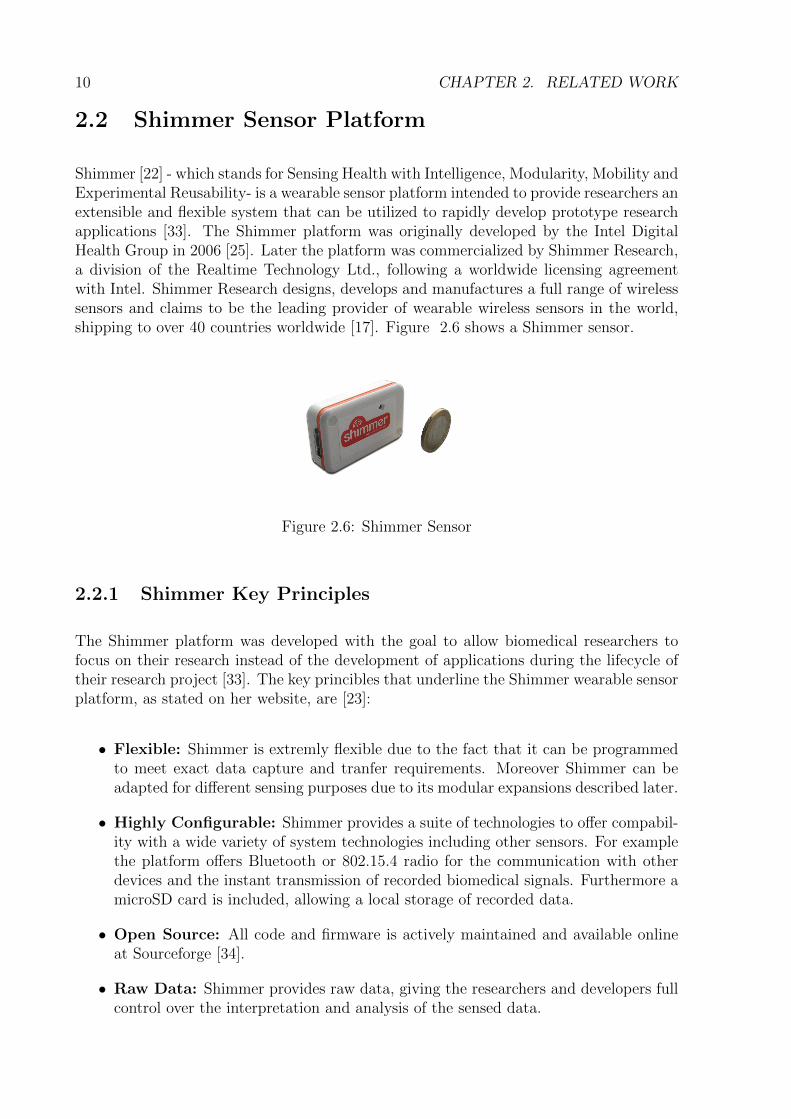
Shimmer [22] - which stands for Sensing Health with Intelligence, Modularity, Mobility andExperimental Reusability- is a wearable sensor platform intended to provide researchers anextensible and flexible system that can be utilized to rapidly develop prototype researchapplications [33]. The Shimmer platform was originally developed by the Intel DigitalHealth Group in 2006 [25]. Later the platform was commercialized by Shimmer Research,a division of the Realtime Technology Ltd., following a worldwide licensing agreementwith Intel. Shimmer Research designs, develops and manufactures a full range of wirelesssensors and claims to be the leading provider of wearable wireless sensors in the world,shipping to over 40 countries worldwide [17]. Figure 2.6 shows a Shimmer sensor.
Figure 2.6: Shimmer Sensor
2.2.1 Shimmer Key Principles
The Shimmer platform was developed with the goal to allow biomedical researchers tofocus on their research instead of the development of applications during the lifecycle oftheir research project [33]. The key princibles that underline the Shimmer wearable sensorplatform, as stated on her website, are [23]:
• Flexible: Shimmer is extremly flexible due to the fact that it can be programmedto meet exact data capture and tranfer requirements. Moreover Shimmer can beadapted for different sensing purposes due to its modular expansions described later.
• Highly Configurable: Shimmer provides a suite of technologies to offer compabil-ity with a wide variety of system technologies including other sensors. For examplethe platform offers Bluetooth or 802.15.4 radio for the communication with otherdevices and the instant transmission of recorded biomedical signals. Furthermore amicroSD card is included, allowing a local storage of recorded data.
• Open Source: All code and firmware is actively maintained and available onlineat Sourceforge [34].
• Raw Data: Shimmer provides raw data, giving the researchers and developers fullcontrol over the interpretation and analysis of the sensed data.
2.2. SHIMMER SENSOR PLATFORM 11
2.2.2 Shimmer Platform Design
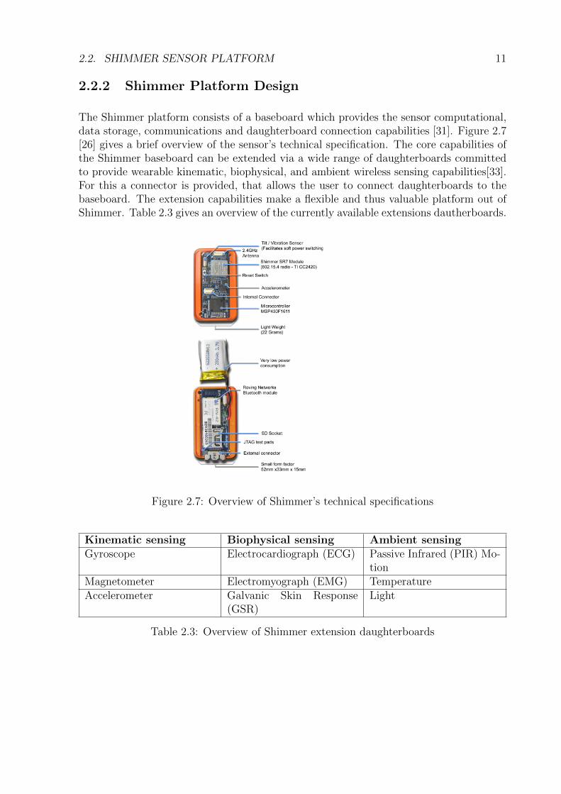
The Shimmer platform consists of a baseboard which provides the sensor computational,data storage, communications and daughterboard connection capabilities [31]. Figure 2.7[26] gives a brief overview of the sensor’s technical specification. The core capabilities ofthe Shimmer baseboard can be extended via a wide range of daughterboards committedto provide wearable kinematic, biophysical, and ambient wireless sensing capabilities[33].For this a connector is provided, that allows the user to connect daughterboards to thebaseboard. The extension capabilities make a flexible and thus valuable platform out ofShimmer. Table 2.3 gives an overview of the currently available extensions dautherboards.
Figure 2.7: Overview of Shimmer’s technical specifications
Kinematic sensing Biophysical sensing Ambient sensingGyroscope Electrocardiograph (ECG) Passive Infrared (PIR) Mo-
tionMagnetometer Electromyograph (EMG) TemperatureAccelerometer Galvanic Skin Response
(GSR)Light
Table 2.3: Overview of Shimmer extension daughterboards
12 CHAPTER 2. RELATED WORK
2.2.3 Shimmer Key Features
The main requirements a wearable sensor should comply in a healthcare environment arecertainly, low power consumption, light weight, small form factor, low power commu-nication capabilities and modularity [30]. These are exactly the features the Shimmerplatform exhibits as consecutively described.
Low Power Consumption
The Shimmer baseboard is equipped with a MSP430 MCU [27] and other hardware tominimize power consumption. Especially the MCU from Texas Instrument is knownfor its low power consumption during periods of inactivity and has a proven history forbiomedical sensing platforms [31]. Further the Shimmer firmware was optimized with focuson lowering the on-time of all hardware subsystems on the sensor hardware platform andthus extends operation life of the sensor [32].
Small Form Factor and Light Weight
With an enclosure size of 53mm x 32mm x 15mm and a weight of 22 gramms the Shimmersensor is perfectly appropriate for sensing biomedical data as a wearable mobile sensor.
Communication Capabilities
One of the key features of Shimmer is certainly its ability to communicate wirelessly withother sensor and devices. For this the Shimmer platform provides two modules: the IEEE802.15.4 radio module and the Bluetooth radio module. The Bluetooth module containsthe full Version 2 Bluetooth Protocol Stack guaranteeing the compatibility with a widerange of other Bluetooth devices like mobile phones.
Firmware
The firmware of Shimmer is primarily developed by using TinyOS [28], a light-weightevent-driven operating system, especially designed for sensor network nodes that havevery limited resources [32]. This firmware provides the low-level capabilities to controlthe sensor functions like: local processing of the sensed data, local storage of the data andcommunication of sensed data to a higher-level application for advanced signal processing,display and data persistence [32]. All Shimmer firmware is therby available online atSourceforge [34].
The operating system TinyOS, is responsible for task scheduling, radio communication,time, I/O processing and has a very small footprint, which makes it suitable for sensordevices [31]. TinyOS is completely written in nesC [29], an extension of the programming
2.3. GOOGLE ANDROID 13
language C. An important concept of nesC is the separation of construction and compo-sition [29]. An application is built out of serveral components, which are assembled toform the whole program. Components are interconnected through their interfaces whichspecifies the components behaviour [29]. This basic concept allows the development ofexchangable and reusable components. Proven components for a specific purpose can bereused in other applications, hence lowering the development time.
The fact that the Shimmer platform is completely open source and provides a rich set ofvaluable features as mentioned above, was the reason to use it for the development of thesystem described in this bachelor thesis. In addition of that it was commercially availableand was easily to be purchased.
2.3 Google Android
Android is an open-source software stack for mobile devices provided by Google and theOpen Handset Alliance (OHA) [7]. The Open Handset Alliance is a group of approxi-mately 78 technology and mobile companies which put their efforts together with the goalto accelerate innovation in mobile and offer better mobile experience to the customer [4].Particulary the group members are committed to openess as stated on their website[5]:
”Each member of the Open Handset Alliance is strongly committed to greateropenness in the mobile ecosystem. Increased openness will enable everyonein our industry to innovate more rapidly and respond better to consumers’demands”.
The following section presents the Android architecture before describing some importantconcepts of the Android SDK.
2.3.1 Android Architecture
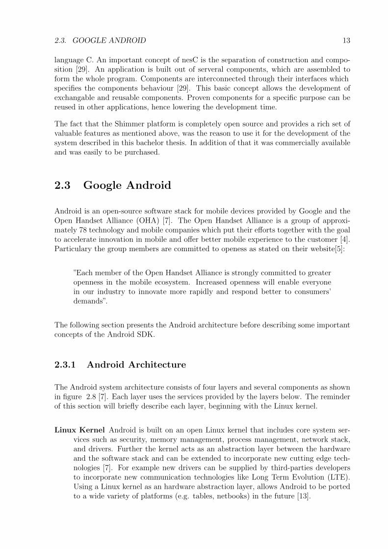
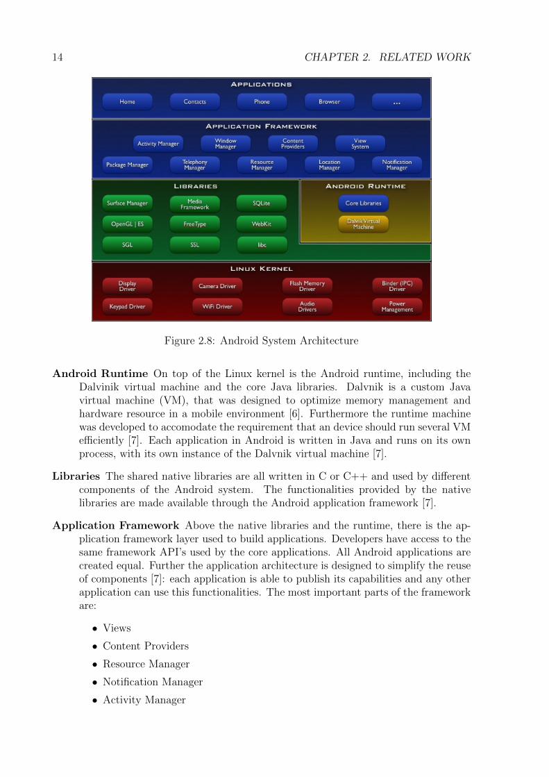
The Android system architecture consists of four layers and several components as shownin figure 2.8 [7]. Each layer uses the services provided by the layers below. The reminderof this section will briefly describe each layer, beginning with the Linux kernel.
Linux Kernel Android is built on an open Linux kernel that includes core system ser-vices such as security, memory management, process management, network stack,and drivers. Further the kernel acts as an abstraction layer between the hardwareand the software stack and can be extended to incorporate new cutting edge tech-nologies [7]. For example new drivers can be supplied by third-parties developersto incorporate new communication technologies like Long Term Evolution (LTE).Using a Linux kernel as an hardware abstraction layer, allows Android to be portedto a wide variety of platforms (e.g. tables, netbooks) in the future [13].
14 CHAPTER 2. RELATED WORK
Figure 2.8: Android System Architecture
Android Runtime On top of the Linux kernel is the Android runtime, including theDalvinik virtual machine and the core Java libraries. Dalvnik is a custom Javavirtual machine (VM), that was designed to optimize memory management andhardware resource in a mobile environment [6]. Furthermore the runtime machinewas developed to accomodate the requirement that an device should run several VMefficiently [7]. Each application in Android is written in Java and runs on its ownprocess, with its own instance of the Dalvnik virtual machine [7].
Libraries The shared native libraries are all written in C or C++ and used by differentcomponents of the Android system. The functionalities provided by the nativelibraries are made available through the Android application framework [7].
Application Framework Above the native libraries and the runtime, there is the ap-plication framework layer used to build applications. Developers have access to thesame framework API’s used by the core applications. All Android applications arecreated equal. Further the application architecture is designed to simplify the reuseof components [7]: each application is able to publish its capabilities and any otherapplication can use this functionalities. The most important parts of the frameworkare:
• Views
• Content Providers
• Resource Manager
• Notification Manager
• Activity Manager
2.3. GOOGLE ANDROID 15
Applications All applications are written using the Java programming language. Theapplication layer includes a set of core applications preinstalled on every Androiddevice including: email, maps, contacts, web browser, phone dialer, calendar, textmessage and Android market. For the development of applications a Software De-velopment Kit (SDK) is provided with the necessary tools and API’s.
2.3.2 Android Components
As mentioned above an Android application can make use of functionalities of otherapplications. In order for this to work, the system should provide the ability to startan application process when any part of it is needed and instantiate the relevant Javaobjects for that part [9]. Consequently Android applications do not have a single entrypoint. Instead an application is made up of components that the system can instatiateindividually and run as needed [9]. Android provides four essential types of components:
Activities
An activity presents a visual user interface for a specific action the user can undertake[9]. For example an address book application might have an activity that shows a list ofall available contacts and a second one that displays the details of the chosen contact.Furthermore an activity might consist of several views like buttons, text fields, scroll bars,menu items, check boxes and more. Views are where the activity’s interaction with theuser takes place [9]. The ”contact detail” activity mentioned above, might for exampleconsist of several text fields displaying contact information of the user like: email, phonenumbers, addresses and buttons to perform actions related to the contact informations.When the user tabs on a button beside a phone number this initiates the action forstarting another activity to write a text message. An application can consist of oneor several activities. What purpose these activities serves and how many activities anapplication consist of, depends on the application and its design [9]. Each activity withinan application is treated independent of the others.
Services
A service is an application component without user interface that runs in the backgroundfor an indefinite period of time [9]. They are perfect to perform ongoing or regular pro-cessing even when the application’s activities are not active, invisible or closed. Androidsupports two types of Services:
Local Service: are not accessible from other applications and thus generally used tosupport the application that is hosting the Service [15].
Remote Service: are accessible from other applications through a well defined interfaceusing the Android Interface Definition Language (AIDL). These kind of services areused for inter-process communication [15].
16 CHAPTER 2. RELATED WORK
Services are launched in the applications main thread, like all other components of theapplication (e.g. activities) [9]. Once a service is started it will live until it is stoppedexplicitely or terminated by the run time’s resource management [14]. The only reasonAndroid will stop a started service is to provide additional resources for a forground com-ponent (usually an active activity) [14]. When that happens the service will be restartedautomatically as soon as resources becomes available again. So because services have thesecond highest priority assigned by Android, they are less likely to be terminated by therun time’s resource management.
A typical example of a service taken from the Android developers website [7], is a mediaplayer playing songs from a play list. The player application might consist of one or moreactivities that allow an user to choose songs and to play them. Though the music playbackitself would not be handled by an activity, because the music has to keep playing evenafter the user leaves the player. To seamlessly keep the music going, the media playeractivity could start a service that runs in the background until explicitly stopped.
Android itself includes several services that can be used. For example the location man-ager, media controller or a notification manager.
Broadcast Receivers
Broadcast receivers are components intended to receive and react on broadcast events [9].In Android many broadcasts originate from the system code such as broadcasts announc-ing network availability, battery status or incoming mails. But an application can alsoinitiate a broadcast itself, informing other applications about an ocurred event. Broadcastreceivers are important components to enable the creation of event-driven applicationsfounded on internal, system or even third-party-application events [14].
Intent
The three components mentioned above can be activated using intents. Intents are ansyn-chronous messages passed between components within an application or between applica-tions and provide a way to turn a collection of independent components into a intercon-nected system. Activities, services and broadcast receivers are activated by intents. Anintent is nothing else than an object that holds the content of the message. For activitiesand services an intent names the action being requested and holds an URI of the datato act on among other things [7]. For example, it may include a request for an activityto display a phone dialer. For broadcast receivers, the intent declares the event (or ac-tion) that occured. For example, it might announce that a new WLAN network has beendetected.
Using intents to pass actions is an fundamental Android design principle which allows thedecoupling of components. Furthermore the decoupling of components allows the seamlessreplacement of application elements and provides the basis for extending an application’scapabilities [14].
2.4. RUBY ON RAILS WEB FRAMEWORK 17
Content Providers
Content providers are used to share the application’s data with other applications onthe device. For this, the content provider extends the ContentProvider base class, andimplements a set of methods to enable other applications to retrieve and store data of thetype it controls [7]. An Application will then use a ContentResolver object to communicateand cooperate with the corresponding provider to retrieve and store data. Like withbroadcast receivers, there are also native content providers that expose databases like themedia store or the contact information. Content providers are the only way to share dataacross applications.
2.4 Ruby on Rails Web Framework
Ruby on Rails (RoR) [16] is an open-source web framework written in the Ruby [18]programming language. It is designed to make the development of web applications easierand more productive by making the assumption that there is a ”best”way to do things[19].Therefore RoR is often mentioned to be an opinonated sofware [19]. RoR applications arebuilt upon two solid principles [19]:
• Don’t Repeat Yourself (DRY): Implies that repeating the code over and overagain is a bad practice and should be avoided.
• Convention over Configuration (CoC): Compared to other web frameworksRoR tries to minimize the needed configuration by making assumption about whata developer wants to do and how he is going to do it. Developers following theconvention of RoR only need to specify unconventional aspects of the application.
2.4.1 Ruby on Rails Architecture
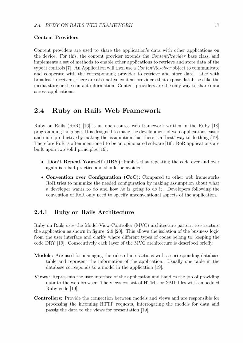
Ruby on Rails uses the Model-View-Controller (MVC) architecture pattern to structurethe application as shown in figure 2.9 [20]. This allows the isolation of the business logicfrom the user interface and clarify where different types of codes belong to, keeping thecode DRY [19]. Consecutively each layer of the MVC architecture is described briefly.
Models: Are used for managing the rules of interactions with a corresponding databasetable and represent the information of the application. Usually one table in thedatabase corresponds to a model in the application [19].
Views: Represents the user interface of the application and handles the job of providingdata to the web browser. The views consist of HTML or XML files with embeddedRuby code [19].
Controllers: Provide the connection between models and views and are responsible forprocessing the incoming HTTP requests, interrogating the models for data andpassig the data to the views for presentation [19].
18 CHAPTER 2. RELATED WORK
Figure 2.9: Ruby on Rails MVC Architecture
Besides the MVC pattern, RoR uses the Representational State Transfer (REST) archi-tecture style [17] by organizing the application around resources and standard HTTPverbs. Each resource in a RoR application is represented by an URL which identifies thatresource. This allows to transfer the representations of the state of a resource betweensystem components [19].
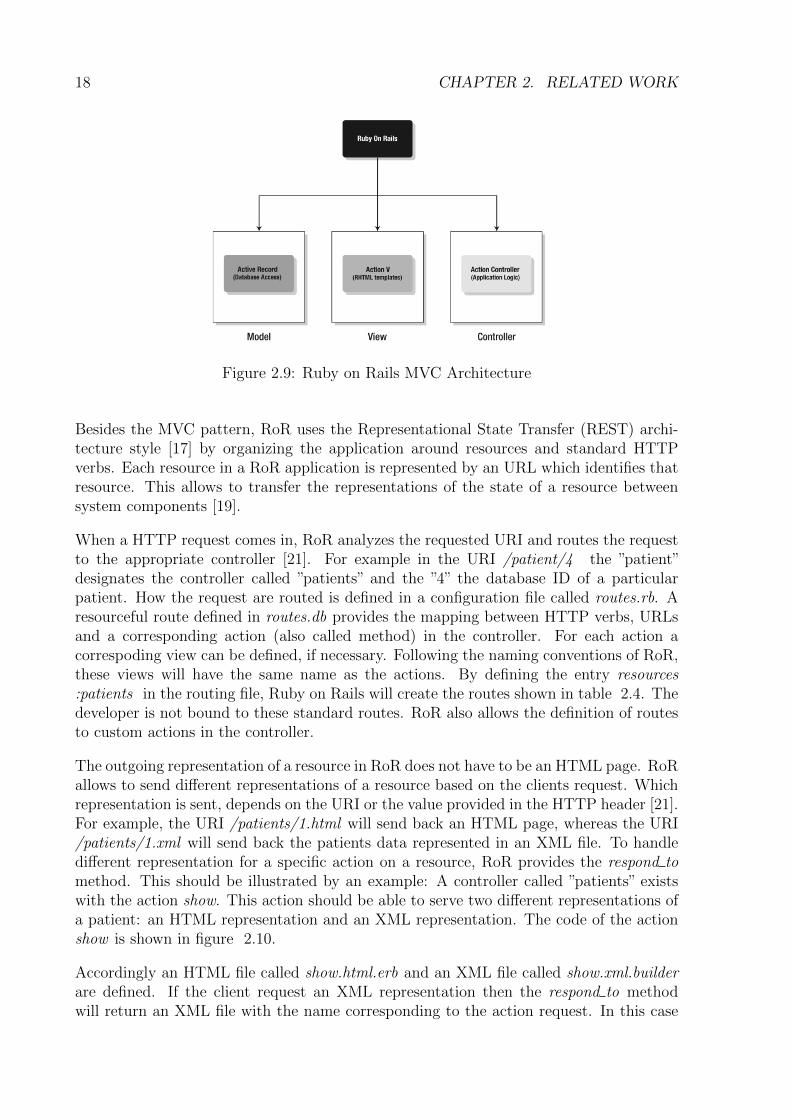
When a HTTP request comes in, RoR analyzes the requested URI and routes the requestto the appropriate controller [21]. For example in the URI /patient/4 the ”patient”designates the controller called ”patients” and the ”4” the database ID of a particularpatient. How the request are routed is defined in a configuration file called routes.rb. Aresourceful route defined in routes.db provides the mapping between HTTP verbs, URLsand a corresponding action (also called method) in the controller. For each action acorrespoding view can be defined, if necessary. Following the naming conventions of RoR,these views will have the same name as the actions. By defining the entry resources:patients in the routing file, Ruby on Rails will create the routes shown in table 2.4. Thedeveloper is not bound to these standard routes. RoR also allows the definition of routesto custom actions in the controller.
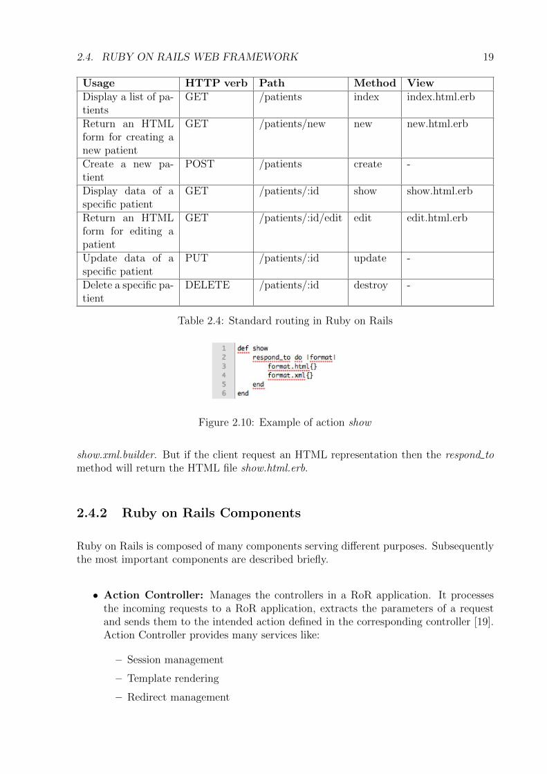
The outgoing representation of a resource in RoR does not have to be an HTML page. RoRallows to send different representations of a resource based on the clients request. Whichrepresentation is sent, depends on the URI or the value provided in the HTTP header [21].For example, the URI /patients/1.html will send back an HTML page, whereas the URI/patients/1.xml will send back the patients data represented in an XML file. To handledifferent representation for a specific action on a resource, RoR provides the respond tomethod. This should be illustrated by an example: A controller called ”patients” existswith the action show. This action should be able to serve two different representations ofa patient: an HTML representation and an XML representation. The code of the actionshow is shown in figure 2.10.
Accordingly an HTML file called show.html.erb and an XML file called show.xml.builderare defined. If the client request an XML representation then the respond to methodwill return an XML file with the name corresponding to the action request. In this case
2.4. RUBY ON RAILS WEB FRAMEWORK 19
Usage HTTP verb Path Method ViewDisplay a list of pa-tients
GET /patients index index.html.erb
Return an HTMLform for creating anew patient
GET /patients/new new new.html.erb
Create a new pa-tient
POST /patients create -
Display data of aspecific patient
GET /patients/:id show show.html.erb
Return an HTMLform for editing apatient
GET /patients/:id/edit edit edit.html.erb
Update data of aspecific patient
PUT /patients/:id update -
Delete a specific pa-tient
DELETE /patients/:id destroy -
Table 2.4: Standard routing in Ruby on Rails
Figure 2.10: Example of action show
show.xml.builder. But if the client request an HTML representation then the respond tomethod will return the HTML file show.html.erb.
2.4.2 Ruby on Rails Components
Ruby on Rails is composed of many components serving different purposes. Subsequentlythe most important components are described briefly.
• Action Controller: Manages the controllers in a RoR application. It processesthe incoming requests to a RoR application, extracts the parameters of a requestand sends them to the intended action defined in the corresponding controller [19].Action Controller provides many services like:
– Session management
– Template rendering
– Redirect management
20 CHAPTER 2. RELATED WORK
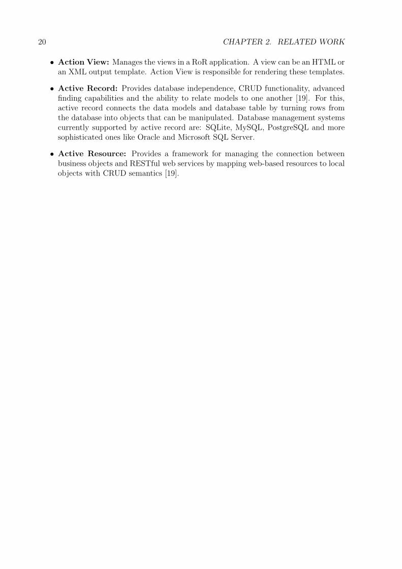
• Action View: Manages the views in a RoR application. A view can be an HTML oran XML output template. Action View is responsible for rendering these templates.
• Active Record: Provides database independence, CRUD functionality, advancedfinding capabilities and the ability to relate models to one another [19]. For this,active record connects the data models and database table by turning rows fromthe database into objects that can be manipulated. Database management systemscurrently supported by active record are: SQLite, MySQL, PostgreSQL and moresophisticated ones like Oracle and Microsoft SQL Server.
• Active Resource: Provides a framework for managing the connection betweenbusiness objects and RESTful web services by mapping web-based resources to localobjects with CRUD semantics [19].
Chapter 3
Design
This chapter describes the design of the mobile healthcare system. In the first section thecontext and the global requirements of the intended system are presented. Based on thedefined global requirements, more fine grained requirements for the different componentsof the system will be derived. These requirements form the base for the design andarchitecture decisions, presented in the second section.
3.1 Requirements
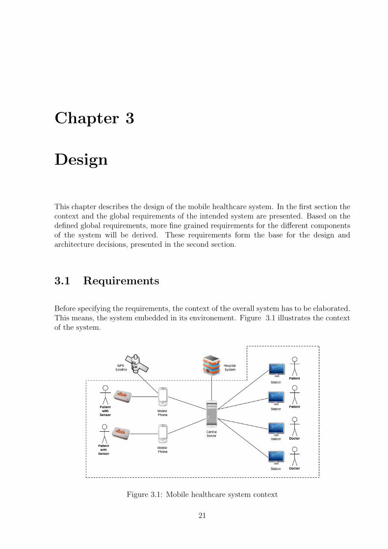
Before specifying the requirements, the context of the overall system has to be elaborated.This means, the system embedded in its environement. Figure 3.1 illustrates the contextof the system.
Figure 3.1: Mobile healthcare system context
21
22 CHAPTER 3. DESIGN
The patients use the Shimmer sensor to record their ECG signal. The recorded data willbe sent to a mobile phone, which acts as a gateway by forwarding the data to a centralserver. Through a web interface the patients and their doctors will be able to see therecorded ECG signal. Doctors can then diagnose the ECG signal of their patients andgive some recommendations. Additionally the mobile phone could monitor the position ofthe patient, using GPS and send it together with the ECG data to the server. This wouldallow, to relate the ECG signal to the position of the patient and derive the pace he ismoving at. Furthermore the server could be connected over a well defined interface, to thehospital system, to retrieve additional information about the patient. As shown in figure3.1, the last two scenarios are outside of the system context and were not consideredduring the development of the mobile healthcare system.
Based on the context described, the global system requirements in table 3.1 were defined.
No. Requirement DescriptionR1 End-to-End system Recorded biomedical data shall seamlessly be transmitted
from the sensor through a mobile phone to a central serverR2 Flexible architecture The architecture should be flexible enough, in order to
support different types of medical or environmental data.
Table 3.1: Overall system requirements
In the follwing section refined requirements for each component of the system are specifiedtaking into account the previously defined global requirements.
3.1.1 The Sensor Component
This section presents the requirements specified for the sensor component. Table 3.2summarizes the defined requirements.
No. Requirement DescriptionR3 Record ECG data The sensor records raw ECG data in real-time.R4 Transmit ECG data The sensor transmits the recorded data wirelessly to
the mobile application.R5 Remote control of sensor It should be possible to start and stop the recording of
data, by sending corresponding commands wirelesslyto the sensor.
R6 Use of defined protocol A defined protocol should be used to send recordeddata. Further the protocol should support the trans-mission of different types of biomedical data.
Table 3.2: Requirements for the sensor component
3.1. REQUIREMENTS 23
3.1.2 The Mobile Component
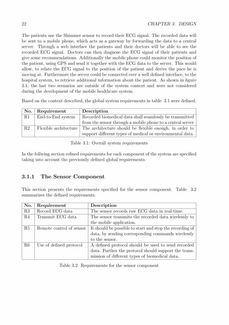
Use cases have been specified for the mobile application, to get a sense of the behavior ofthe application. Figure 3.2 gives an overview of the use cases defined.
Figure 3.2: Use cases for the mobile application
The user starts the mobile application and authenticates with the server. This will allowthe mobile application to periodically send data to the server. Furthermore the usercan connect the mobile phone with a sensor. After connecting the devices, the mobileapplication starts to periodically request biomedical data from the sensor. The receiveddata will then be stored in a database.
Table 3.3 lists all the requirements specified for the mobile application. These require-ments are partly grounded on the use cases, illustrated previously.
No. Requirement DescriptionR7 Authenticate with server The user should be able to authenticate with the
server.R8 Establish connection to
sensorThe user should be able to establish a Bluetoothconnection with the sensor and later to disconnect.
R9 Periodically requestbiomedical data
The mobile application should periodically requestbiomedical data from the sensor.
R10 Receiving biomedical data The mobile application should be able to sup-port the protocol, defined by the sensor for thetransmission of biomedical data. Thereby the mo-bile application should be able to receive differenttypes of biomedical and environmental data.
24 CHAPTER 3. DESIGN
R12 Store biomedical data The mobile application should store the receivedbiomedical data in a database. This is needed, asthere could not be guaranteed that a network isavailable to forward the data.
R13 Extensible database The database should be designed in a way to beflexible enough, in order to support different typesof biomedical or environmental data.
R14 Periodically sendbiomedical data
The mobile application should periodically sendstored biomedical data to the server, using aHTTP-based protocol.
R15 Delete biomedical data Biomedical data sent to the server should bedeleted in the database to guarantee, that enoughmemory space is always available at any time.
R16 Background tasks The mobile application should be able to receiveand send biomedical data, even if the applicationis not active on the mobile phone.
Table 3.3: Requirements for the mobile component
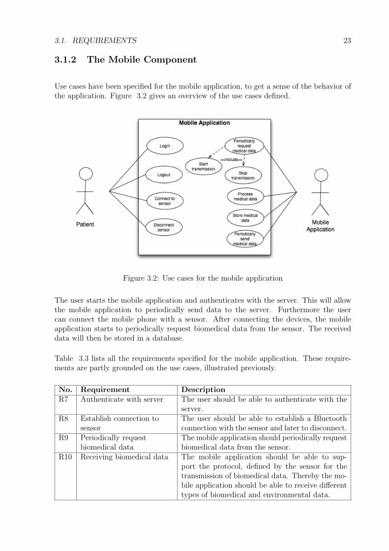
3.1.3 The Server Component
The following use cases were specified to describe the behavior of the web server applica-tion. The use cases are illustrated in Figure 3.3.
Figure 3.3: Use cases for the web server application
3.1. REQUIREMENTS 25
The web server application will be used by two types of users: patients and doctors. Thedoctor registers to the web application and receives a confirmation mail, to activate hisaccount. After activation, the doctor can log in and invite patients by providing an emailaddress. The patient will receive an invitation mail including an URL, pointing the website for registration. After successful registration and activation of the account, the usercan access the web application. From this point on, the patient can use the sensor and themobile phone to send recorded ECG data to the server as described previously. Furtherthe patient will be added to the list of patients of the doctor. The doctor is now able tosee the ECG data of the patient and write a diagnosis in form of a comment. This willbe displayed to the user, which is able to ask questions about the diagnosis. Some sortof basic asynchronous communication will then be possible between the patient and thedoctor.
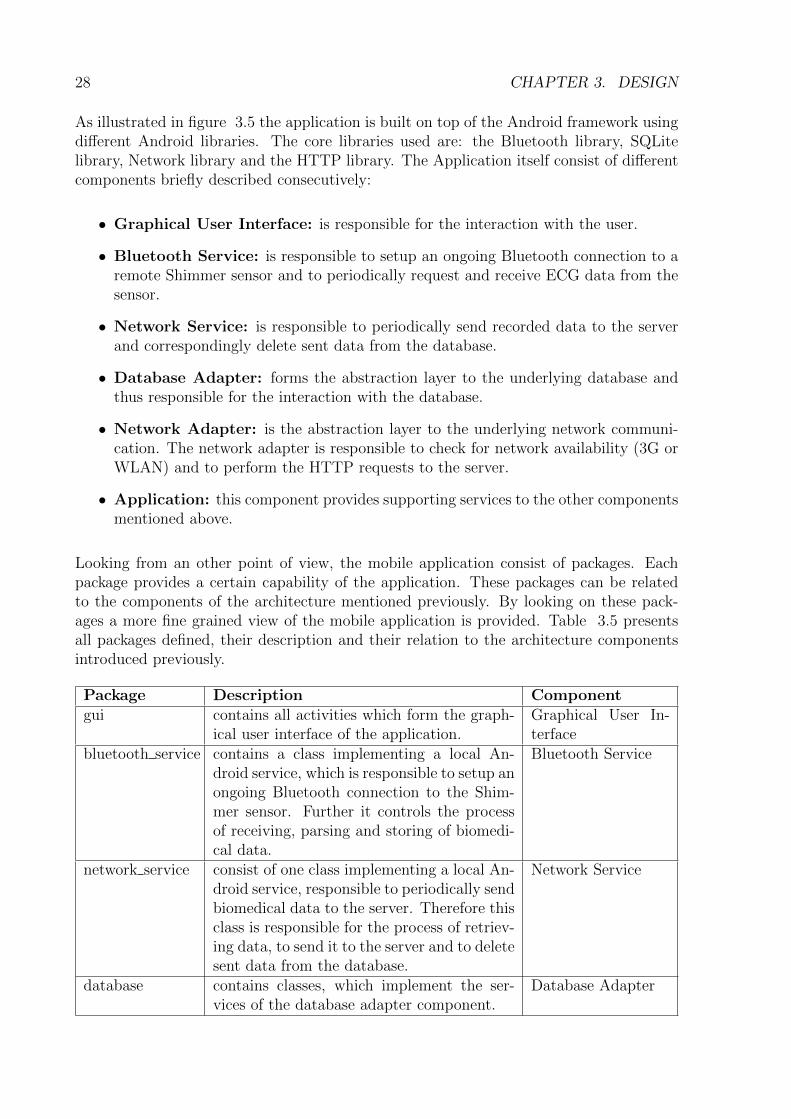
Based on the use cases presented, the following requirements in table 3.4 were specified.
R17 Authentication The web application should include an authenticationsystem and handling session management.
R18 Authorization The web application should include a simple autho-rization system, allowing the user only to access theressources, they are allowed to.
R19 Edit personal data User should be able to edit their personal data.R20 Receive biomedical data The web server application should be able to receive
biomedical data sent, using an HTTP-based ProtocolR20 Store biomedical data The web server application should be able to store the
biomedical data, received by the mobile applicationR22 Display ECG The web server application should contain a visualiza-
tion module, to graphically display the stored ECGdata of a patient.
R23 ECG Assessment The web server application should contain a module,allowing basic medical assessment of patients.
R24 Extensible database The database should be designed in a way, to be flexi-ble enough in order to support different types of med-ical or environmental data
R25 Extensible user interface The user interface of the web server application shouldbe designed in a way, to be easily extended with newservices.
Table 3.4: Requirements for the web server application
26 CHAPTER 3. DESIGN
3.2 Architecture
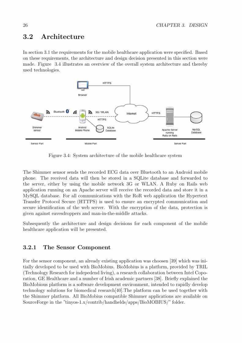
In section 3.1 the requirements for the mobile healthcare application were specified. Basedon these requirements, the architecture and design decision presented in this section weremade. Figure 3.4 illustrates an overview of the overall system architecture and therebyused technologies.
Figure 3.4: System architecture of the mobile healthcare system
The Shimmer sensor sends the recorded ECG data over Bluetooth to an Android mobilephone. The received data will then be stored in a SQLite database and forwarded tothe server, either by using the mobile network 3G or WLAN. A Ruby on Rails webapplication running on an Apache server will receive the recorded data and store it in aMySQL database. For all communications with the RoR web application the HypertextTransfer Protocol Secure (HTTPS) is used to ensure an encrypted communication andsecure identification of the web server. With the encryption of the data, protection isgiven against eavesdroppers and man-in-the-middle attacks.
Subsequently the architecture and design decisions for each component of the mobilehealthcare application will be presented.
3.2.1 The Sensor Component
For the sensor component, an already existing application was choosen [39] which was ini-tially developed to be used with BioMobius. BioMobius is a platform, provided by TRIL(Technology Research for indepedend living), a research collaboration between Intel Copo-ration, GE Healthcare and a number of Irish academic partners [38]. Briefly explained theBioMobious platform is a software development environment, intended to rapidly developtechnology solutions for biomedical research[40].The platform can be used together withthe Shimmer platform. All BioMobius compatible Shimmer applications are available onSourceForge in the ”tinyos-1.x/contrib/handhelds/apps/BioMOBIUS/” folder.
3.2. ARCHITECTURE 27
The application called ”ECG” was chosen, because it fully satisfied all requirements spec-ified preliminarily:
• record raw ECG data.
• send recorded data of a Bluetooth connection.
• allows to control the recording remotely by sending corresponding start and stopcommands.
• provide an extensible protocol regarding the type of biomedical data to be sent.
It is worth noting that the copyright notice [39] of the application explicitly allows theredistribution and the modification of the binary source code and therefore the applicationcould be used for this project.
3.2.2 The Mobile Component
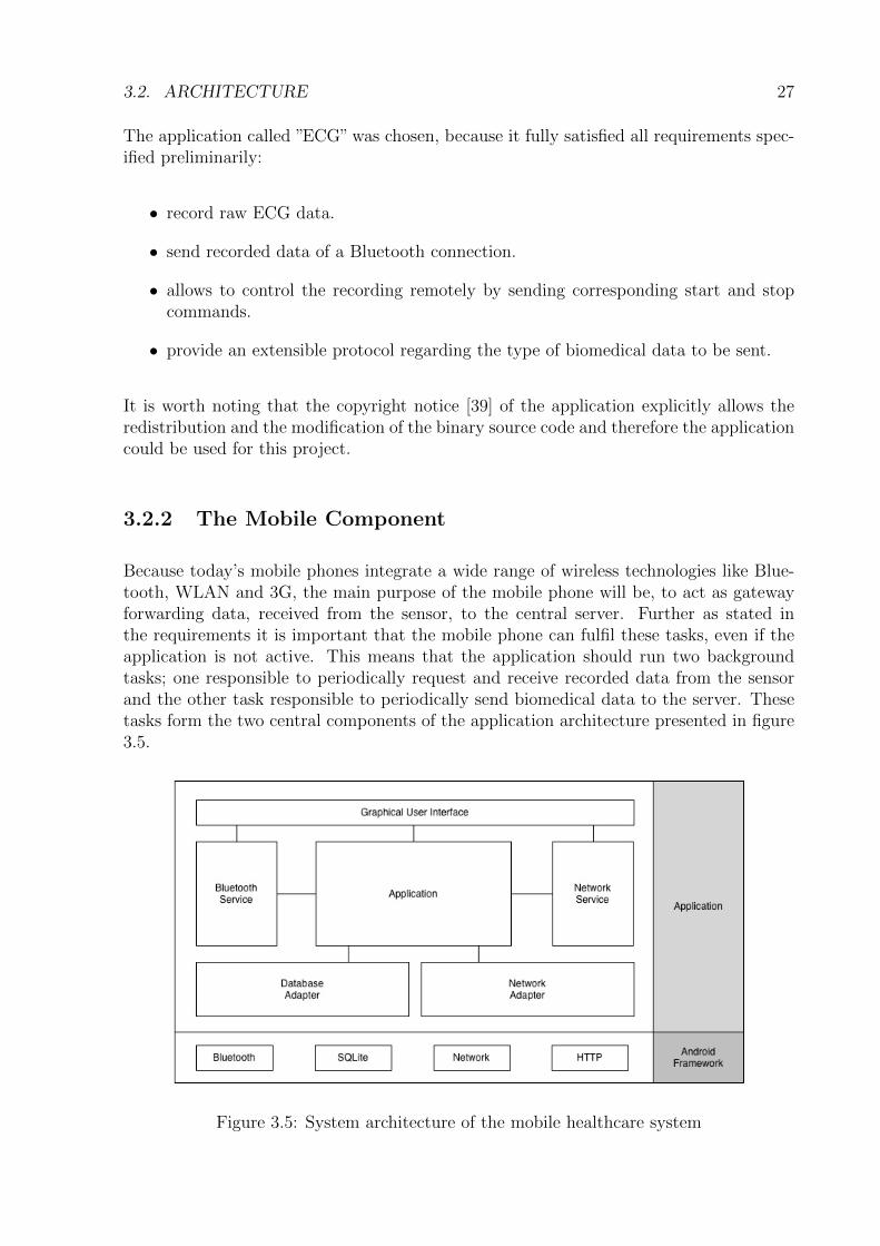
Because today’s mobile phones integrate a wide range of wireless technologies like Blue-tooth, WLAN and 3G, the main purpose of the mobile phone will be, to act as gatewayforwarding data, received from the sensor, to the central server. Further as stated inthe requirements it is important that the mobile phone can fulfil these tasks, even if theapplication is not active. This means that the application should run two backgroundtasks; one responsible to periodically request and receive recorded data from the sensorand the other task responsible to periodically send biomedical data to the server. Thesetasks form the two central components of the application architecture presented in figure3.5.
Figure 3.5: System architecture of the mobile healthcare system
28 CHAPTER 3. DESIGN
As illustrated in figure 3.5 the application is built on top of the Android framework usingdifferent Android libraries. The core libraries used are: the Bluetooth library, SQLitelibrary, Network library and the HTTP library. The Application itself consist of differentcomponents briefly described consecutively:
• Graphical User Interface: is responsible for the interaction with the user.
• Bluetooth Service: is responsible to setup an ongoing Bluetooth connection to aremote Shimmer sensor and to periodically request and receive ECG data from thesensor.
• Network Service: is responsible to periodically send recorded data to the serverand correspondingly delete sent data from the database.
• Database Adapter: forms the abstraction layer to the underlying database andthus responsible for the interaction with the database.
• Network Adapter: is the abstraction layer to the underlying network communi-cation. The network adapter is responsible to check for network availability (3G orWLAN) and to perform the HTTP requests to the server.
• Application: this component provides supporting services to the other componentsmentioned above.
Looking from an other point of view, the mobile application consist of packages. Eachpackage provides a certain capability of the application. These packages can be relatedto the components of the architecture mentioned previously. By looking on these pack-ages a more fine grained view of the mobile application is provided. Table 3.5 presentsall packages defined, their description and their relation to the architecture componentsintroduced previously.
Package Description Componentgui contains all activities which form the graph-
ical user interface of the application.Graphical User In-terface
bluetooth service contains a class implementing a local An-droid service, which is responsible to setup anongoing Bluetooth connection to the Shim-mer sensor. Further it controls the processof receiving, parsing and storing of biomedi-cal data.
Bluetooth Service
network service consist of one class implementing a local An-droid service, responsible to periodically sendbiomedical data to the server. Therefore thisclass is responsible for the process of retriev-ing data, to send it to the server and to deletesent data from the database.
Network Service
database contains classes, which implement the ser-vices of the database adapter component.
Database Adapter
3.2. ARCHITECTURE 29
network implements the network adapter of the archi-tecture
Network Adapter
parser this package is part of the application compo-nent and includes all parsers needed to parsepackets sent from the sensor and to parseHTTP messages received from the server.
Application
record will be extensively used by the applicationto send received biomedical data from oneclass to another class in a structured way.Therefore it provides a well defined messageformat for records.
Application
utils contains classes providing support for thecore functionalities of the application. Forexample this package contains a class pro-viding the service to calculate an 16bit crc-checksum. This checksum is needed to check,if a received packet of the sensor is erroneousor not.
Application
Table 3.5: Package structure of the mobile phone application
Communication
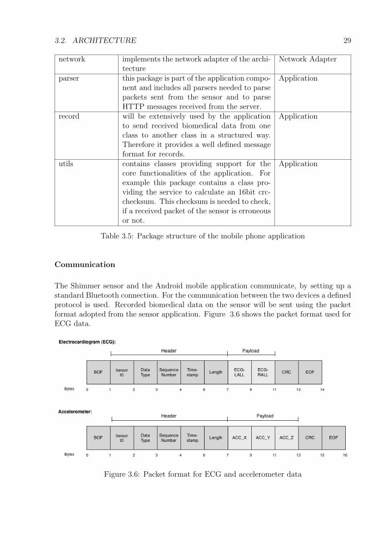
The Shimmer sensor and the Android mobile application communicate, by setting up astandard Bluetooth connection. For the communication between the two devices a definedprotocol is used. Recorded biomedical data on the sensor will be sent using the packetformat adopted from the sensor application. Figure 3.6 shows the packet format used forECG data.
Figure 3.6: Packet format for ECG and accelerometer data
30 CHAPTER 3. DESIGN
The fields of the ECG packet are defined as follow:
• BOF: binary value that marks the begin of the packet.
• Sensor ID: contains the identification number of the sensor used.
• Data Type: a number indicating the content of the payload. Based on the datatype the receiving device knows what data to expect in the payload. For example:
– ECG = 255
– EMG = 254
– GRS = 253
• Sequence Number: used to check, if the packets are received in order.
• Timestamp: indicating the time, the record has been taken. Primarily used tocalculate the time interval between two consecutive recorded values.
• Length: indicates the length of the payload.
• ECG-LALL: recorded value for Lead 2 (see section 2.2.2)
• ECG-RALL: recorded value for Lead 3 (see section 2.2.2)
• CRC: checksum to check if the packet is erroneous.
• EOF: binary value that marks the end of the packet
The content of the packet fields contain binary data. Further the packet could have avariable payload length, thus supporting different types of recorded biomedical data. Thisallows to fulfil the requirement, that the protocol should be extensible regarding the datarecorded by the sensor. For example the payload of the accelerometer packet shown inFigure 3.6 was extended to be able to send the values of each recorded axis.
Database
The mobile phone will store the recorded data in a SQLite database [41]. This is neededbecause it cannot be assumed that there will always be a network available to forwardthe biomedical data to the server.
Before describing how the database schema was designed, two important terms should beintroduced:
• Record: A record corresponds to what the sensor records in a specific point intime. In other words: a packet send by the sensor.
• Trace: A trace is a set of records, acquired in a certain period of time. In otherwords: a set of packets.
3.2. ARCHITECTURE 31
When designing a database schema it is important to think about how the database wouldbe used. The database would primarily be used to:
• store records of different types. This corresponds to the specified requirement R13(see section 3.1.2): the database should be designed in a way to be flexible enoughin order to support different types of biomedical data
• retrieve a trace recorded in a specific period of time.
• retrieve all records currently not send to the database.
• delete a single record or a single trace.
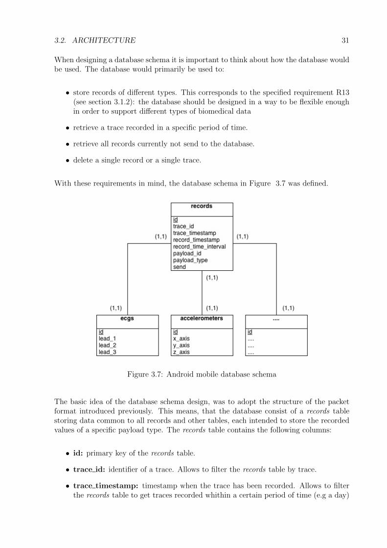
With these requirements in mind, the database schema in Figure 3.7 was defined.
Figure 3.7: Android mobile database schema
The basic idea of the database schema design, was to adopt the structure of the packetformat introduced previously. This means, that the database consist of a records tablestoring data common to all records and other tables, each intended to store the recordedvalues of a specific payload type. The records table contains the following columns:
• id: primary key of the records table.
• trace id: identifier of a trace. Allows to filter the records table by trace.
• trace timestamp: timestamp when the trace has been recorded. Allows to filterthe records table to get traces recorded whithin a certain period of time (e.g a day)
32 CHAPTER 3. DESIGN
• record timestamp: correspond to the timestamp of the packet header.
• record time interval: is the interval between current record timestamp and thepreviously received record timestamp.
• payload type: includes the name of the table, where the payload values are stored.
• payload id: a foreign key pointing to the row in the payload table, containing therecorded values.
• send: marks, if the record has already be sent to the server or not.
– 0 - not sent
– 1 - sent
The columns payload type and payload id are used to get the right payload values belong-ing to a record. By separating the records table from the tables containing the payloadvalues, the database can be easily extended to store different payload types. An exampleshould illustrate this: For an ECG packet the value of the header fields will be stored inthe corresponding columns of the records table and the payload values in a table calledecgs with the columns lead 1, lead 2 and lead 3. Likewise an accelerometer packet willbe stored. But the payload values of the packet will be stored in another table calledaccelerometers.
3.2.3 The Server Component:
The Ruby on Rails framework was chosen to develop the web application. The mainreason why RoR was used, can be summarized as follow:
• RoR puts convention over configuration [19]. By following the conventions of RoR,the framework takes a lot of work common for each web application, allowing thedeveloper to concentrate on the important task.
• RoR gives a structure how a web application should be organized. This has two mainadvantages. First the developer gets familiar quickly with the RoR framework,accelerating the development of the application. Secondly other developers whowant to extend the application later, quickly get an overview of the application.
• RoR web application can be easily extended by plugins for common functionalities,like authorization and authentication. This is especially an advantage for the devel-opment of a prototype web application. By using plugins for common functionalitiesof a web application, the developer can concentrate on the specific and importantfunctions. Furthermore, many plugins are widely used and therefore reliable androbust.
3.2. ARCHITECTURE 33
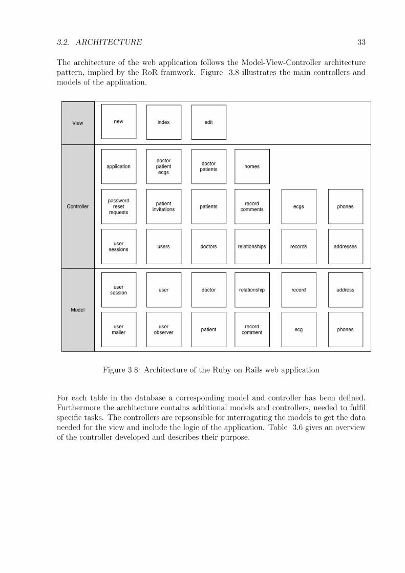
The architecture of the web application follows the Model-View-Controller architecturepattern, implied by the RoR framwork. Figure 3.8 illustrates the main controllers andmodels of the application.
Figure 3.8: Architecture of the Ruby on Rails web application
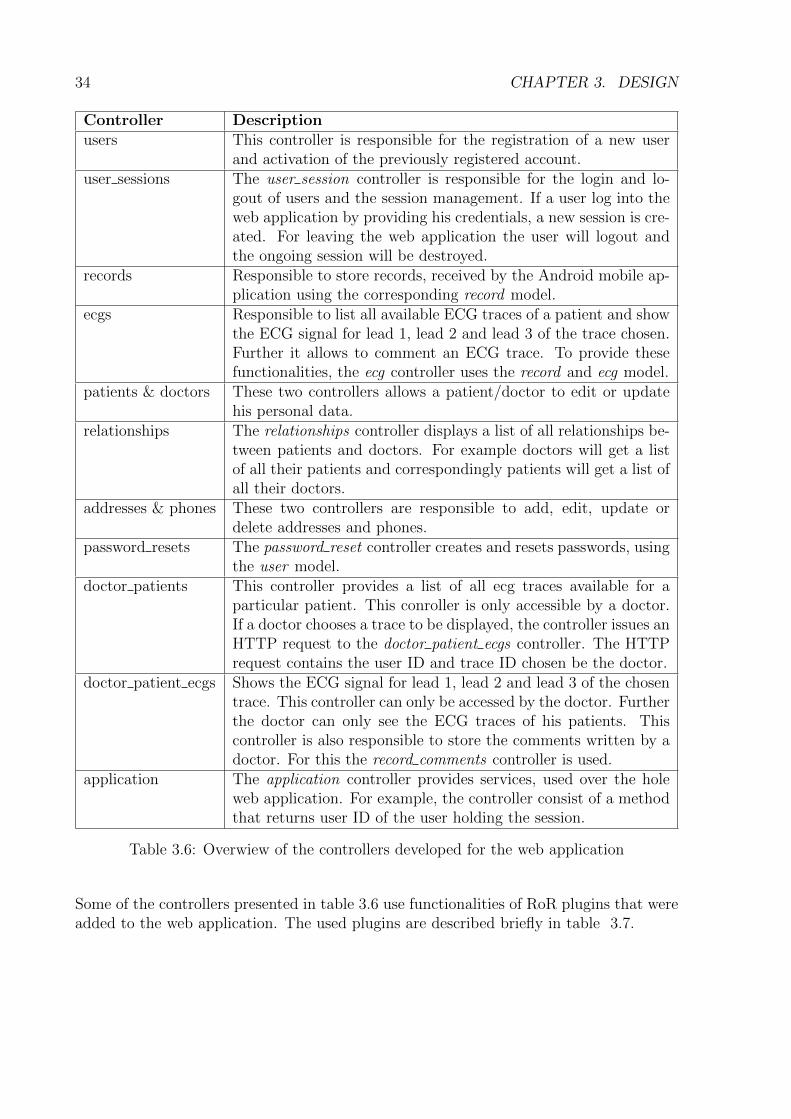
For each table in the database a corresponding model and controller has been defined.Furthermore the architecture contains additional models and controllers, needed to fulfilspecific tasks. The controllers are repsonsible for interrogating the models to get the dataneeded for the view and include the logic of the application. Table 3.6 gives an overviewof the controller developed and describes their purpose.
34 CHAPTER 3. DESIGN
Controller Descriptionusers This controller is responsible for the registration of a new user
and activation of the previously registered account.user sessions The user session controller is responsible for the login and lo-
gout of users and the session management. If a user log into theweb application by providing his credentials, a new session is cre-ated. For leaving the web application the user will logout andthe ongoing session will be destroyed.
records Responsible to store records, received by the Android mobile ap-plication using the corresponding record model.
ecgs Responsible to list all available ECG traces of a patient and showthe ECG signal for lead 1, lead 2 and lead 3 of the trace chosen.Further it allows to comment an ECG trace. To provide thesefunctionalities, the ecg controller uses the record and ecg model.
patients & doctors These two controllers allows a patient/doctor to edit or updatehis personal data.
relationships The relationships controller displays a list of all relationships be-tween patients and doctors. For example doctors will get a listof all their patients and correspondingly patients will get a list ofall their doctors.
addresses & phones These two controllers are responsible to add, edit, update ordelete addresses and phones.
password resets The password reset controller creates and resets passwords, usingthe user model.
doctor patients This controller provides a list of all ecg traces available for aparticular patient. This conroller is only accessible by a doctor.If a doctor chooses a trace to be displayed, the controller issues anHTTP request to the doctor patient ecgs controller. The HTTPrequest contains the user ID and trace ID chosen be the doctor.
doctor patient ecgs Shows the ECG signal for lead 1, lead 2 and lead 3 of the chosentrace. This controller can only be accessed by the doctor. Furtherthe doctor can only see the ECG traces of his patients. Thiscontroller is also responsible to store the comments written by adoctor. For this the record comments controller is used.
application The application controller provides services, used over the holeweb application. For example, the controller consist of a methodthat returns user ID of the user holding the session.
Table 3.6: Overwiew of the controllers developed for the web application
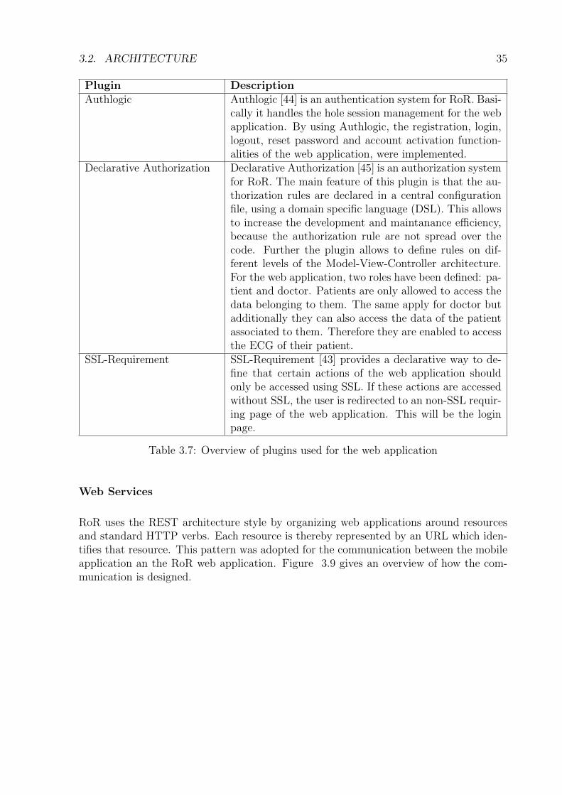
Some of the controllers presented in table 3.6 use functionalities of RoR plugins that wereadded to the web application. The used plugins are described briefly in table 3.7.
3.2. ARCHITECTURE 35
Plugin DescriptionAuthlogic Authlogic [44] is an authentication system for RoR. Basi-
cally it handles the hole session management for the webapplication. By using Authlogic, the registration, login,logout, reset password and account activation function-alities of the web application, were implemented.
Declarative Authorization Declarative Authorization [45] is an authorization systemfor RoR. The main feature of this plugin is that the au-thorization rules are declared in a central configurationfile, using a domain specific language (DSL). This allowsto increase the development and maintanance efficiency,because the authorization rule are not spread over thecode. Further the plugin allows to define rules on dif-ferent levels of the Model-View-Controller architecture.For the web application, two roles have been defined: pa-tient and doctor. Patients are only allowed to access thedata belonging to them. The same apply for doctor butadditionally they can also access the data of the patientassociated to them. Therefore they are enabled to accessthe ECG of their patient.
SSL-Requirement SSL-Requirement [43] provides a declarative way to de-fine that certain actions of the web application shouldonly be accessed using SSL. If these actions are accessedwithout SSL, the user is redirected to an non-SSL requir-ing page of the web application. This will be the loginpage.
Table 3.7: Overview of plugins used for the web application
Web Services
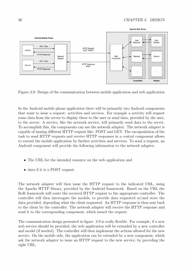
RoR uses the REST architecture style by organizing web applications around resourcesand standard HTTP verbs. Each resource is thereby represented by an URL which iden-tifies that resource. This pattern was adopted for the communication between the mobileapplication an the RoR web application. Figure 3.9 gives an overview of how the com-munication is designed.
36 CHAPTER 3. DESIGN
Figure 3.9: Design of the communication between mobile application and web application
In the Android mobile phone application there will be primarily two Android componentsthat want to issue a request: activities and services. For example a activity will requestsome data from the server to display these to the user or send data, provided by the user,to the server. A service, like the network service, will primarily send data to the server.To accomplish this, the components can use the network adapter. The network adapter iscapable of issuing different HTTP request like: POST and GET. The encapsulation of thetask to send HTTP requests and receive HTTP responses in a central component allowsto extend the mobile application by further activities and services. To send a request, anAndroid component will provide the following information to the network adapter:
• The URL for the intended resource on the web application and
• data if it is a POST request.
The network adapter will then issue the HTTP request to the indicated URL, usingthe Apache HTTP library, provided by the Android framework. Based on the URL theRoR framework will route the received HTTP request to the appropriate controller. Thecontroller will then interrogate the models, to provide data requested or/and store thedata provided, depending what the client requested. An HTTP response is then sent backto the client by the controller. The network adapter will receive the HTTP response andsend it to the corresponding component, which issued the request.
The communication design presented in figure 3.9 is really flexible. For example, if a newweb service should be provided, the web application will be extended by a new controllerand model (if needed). The controller will then implement the actions allowed for the newservice. On the mobile side, the application can be extended by a new component, whichask the network adapter to issue an HTTP request to the new service, by providing theright URL.
3.2. ARCHITECTURE 37
Database
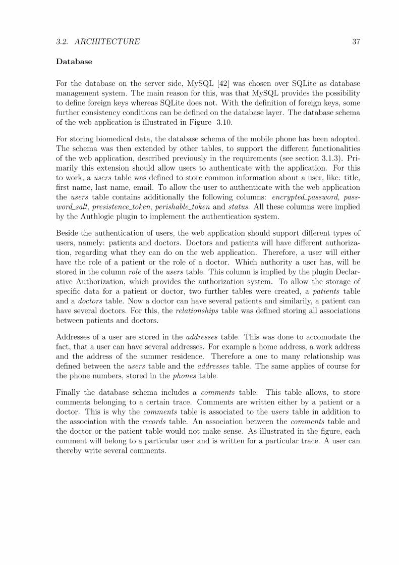
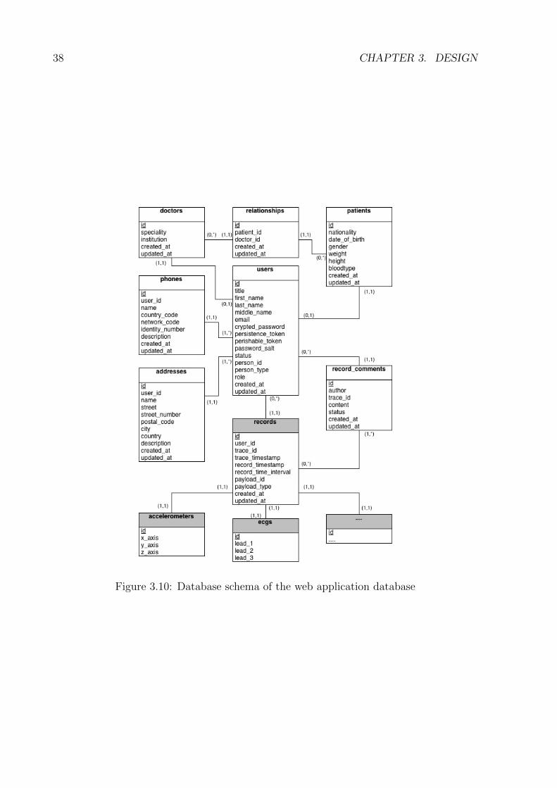
For the database on the server side, MySQL [42] was chosen over SQLite as databasemanagement system. The main reason for this, was that MySQL provides the possibilityto define foreign keys whereas SQLite does not. With the definition of foreign keys, somefurther consistency conditions can be defined on the database layer. The database schemaof the web application is illustrated in Figure 3.10.
For storing biomedical data, the database schema of the mobile phone has been adopted.The schema was then extended by other tables, to support the different functionalitiesof the web application, described previously in the requirements (see section 3.1.3). Pri-marily this extension should allow users to authenticate with the application. For thisto work, a users table was defined to store common information about a user, like: title,first name, last name, email. To allow the user to authenticate with the web applicationthe users table contains additionally the following columns: encrypted password, pass-word salt, presistence token, perishable token and status. All these columns were impliedby the Authlogic plugin to implement the authentication system.
Beside the authentication of users, the web application should support different types ofusers, namely: patients and doctors. Doctors and patients will have different authoriza-tion, regarding what they can do on the web application. Therefore, a user will eitherhave the role of a patient or the role of a doctor. Which authority a user has, will bestored in the column role of the users table. This column is implied by the plugin Declar-ative Authorization, which provides the authorization system. To allow the storage ofspecific data for a patient or doctor, two further tables were created, a patients tableand a doctors table. Now a doctor can have several patients and similarily, a patient canhave several doctors. For this, the relationships table was defined storing all associationsbetween patients and doctors.
Addresses of a user are stored in the addresses table. This was done to accomodate thefact, that a user can have several addresses. For example a home address, a work addressand the address of the summer residence. Therefore a one to many relationship wasdefined between the users table and the addresses table. The same applies of course forthe phone numbers, stored in the phones table.
Finally the database schema includes a comments table. This table allows, to storecomments belonging to a certain trace. Comments are written either by a patient or adoctor. This is why the comments table is associated to the users table in addition tothe association with the records table. An association between the comments table andthe doctor or the patient table would not make sense. As illustrated in the figure, eachcomment will belong to a particular user and is written for a particular trace. A user canthereby write several comments.
38 CHAPTER 3. DESIGN
Figure 3.10: Database schema of the web application database
Chapter 4
Implementation
The previous chapter gave a broad overview of the design and architecture of the mobilehealthcare system. In this chapter the implementation details of the main functionalitiesare covered. Thereby some more fine grained design decisions will be presented. Furtheronly the mobile component an the server component are considered, as for the sensorcomponent an already existing application was used.
4.1 Mobile Application
This section first describes how the graphical user interface of the Android mobile appli-cation was implemented. After that the implementation of the two essential services ofthe application are described.
4.1.1 Graphical User Interface
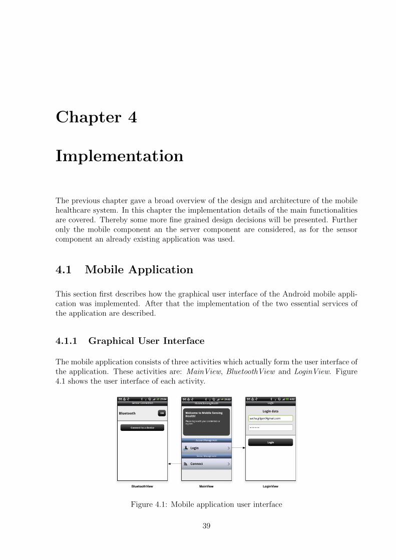
The mobile application consists of three activities which actually form the user interface ofthe application. These activities are: MainView, BluetoothView and LoginView. Figure4.1 shows the user interface of each activity.
Figure 4.1: Mobile application user interface
39
40 CHAPTER 4. IMPLEMENTATION
The MainView is the activity shown to the user when the application is launched. Fromthis activity the other two activities will be started.
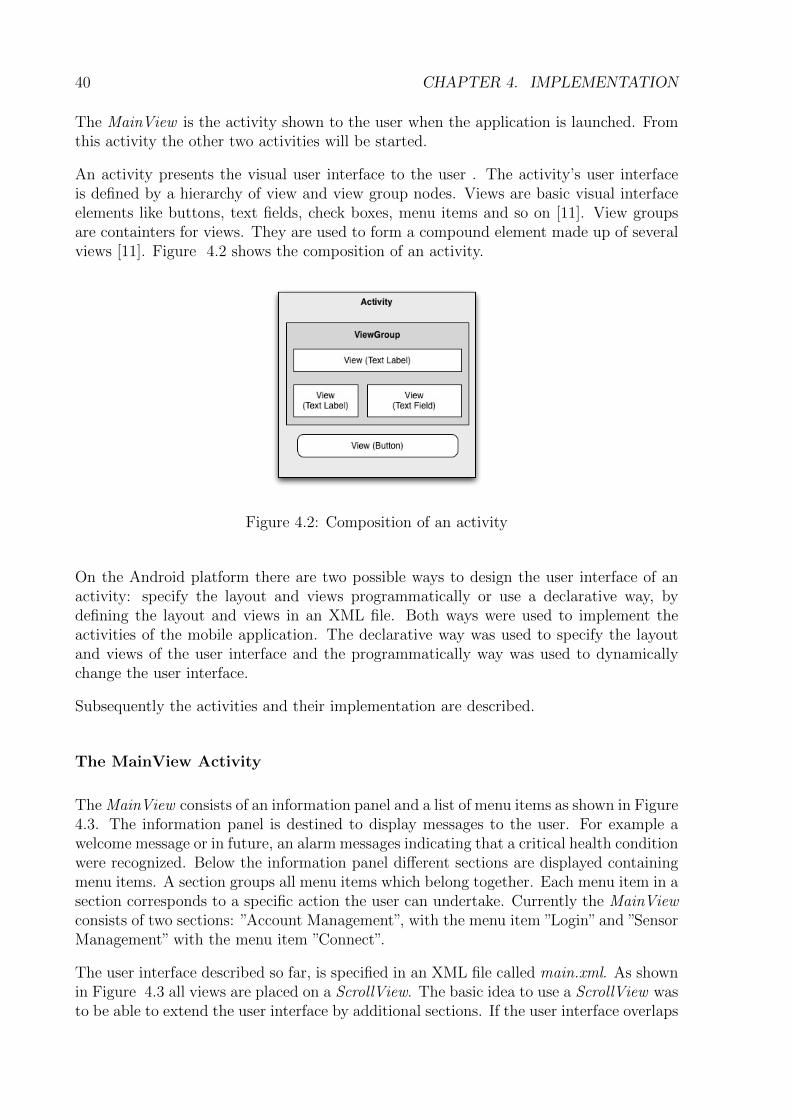
An activity presents the visual user interface to the user . The activity’s user interfaceis defined by a hierarchy of view and view group nodes. Views are basic visual interfaceelements like buttons, text fields, check boxes, menu items and so on [11]. View groupsare containters for views. They are used to form a compound element made up of severalviews [11]. Figure 4.2 shows the composition of an activity.
Figure 4.2: Composition of an activity
On the Android platform there are two possible ways to design the user interface of anactivity: specify the layout and views programmatically or use a declarative way, bydefining the layout and views in an XML file. Both ways were used to implement theactivities of the mobile application. The declarative way was used to specify the layoutand views of the user interface and the programmatically way was used to dynamicallychange the user interface.
Subsequently the activities and their implementation are described.
The MainView Activity
The MainView consists of an information panel and a list of menu items as shown in Figure4.3. The information panel is destined to display messages to the user. For example awelcome message or in future, an alarm messages indicating that a critical health conditionwere recognized. Below the information panel different sections are displayed containingmenu items. A section groups all menu items which belong together. Each menu item in asection corresponds to a specific action the user can undertake. Currently the MainViewconsists of two sections: ”Account Management”, with the menu item ”Login” and ”SensorManagement” with the menu item ”Connect”.
The user interface described so far, is specified in an XML file called main.xml. As shownin Figure 4.3 all views are placed on a ScrollView. The basic idea to use a ScrollView wasto be able to extend the user interface by additional sections. If the user interface overlaps
4.1. MOBILE APPLICATION 41
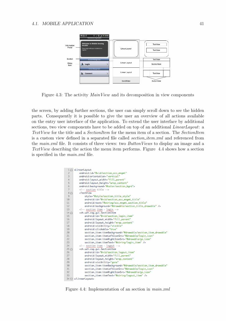
Figure 4.3: The activity MainView and its decomposition in view components
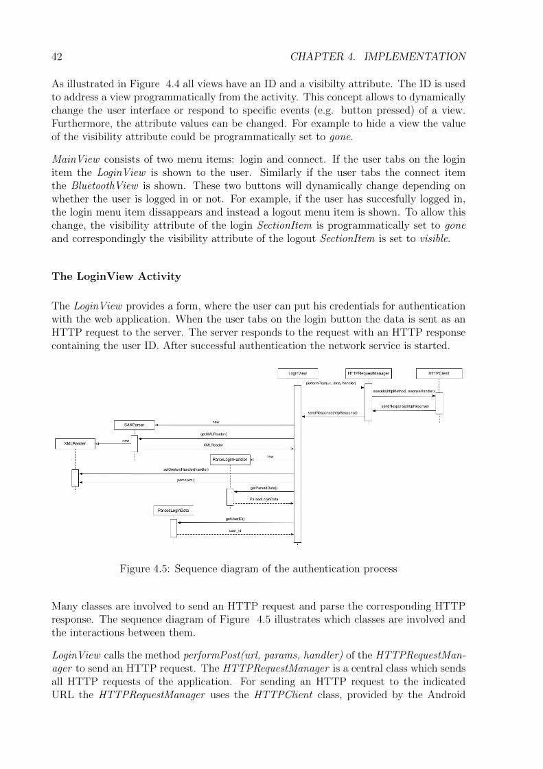
the screen, by adding further sections, the user can simply scroll down to see the hiddenparts. Consequently it is possible to give the user an overview of all actions availableon the entry user interface of the application. To extend the user interface by additionalsections, two view components have to be added on top of an additional LinearLayout : aTextView for the title and a SectionItem for the menu item of a section. The SectionItemis a custom view defined in a separated file called section item.xml and referenced fromthe main.xml file. It consists of three views: two ButtonViews to display an image and aTextView describing the action the menu item performs. Figure 4.4 shows how a sectionis specified in the main.xml file.
Figure 4.4: Implementation of an section in main.xml
42 CHAPTER 4. IMPLEMENTATION
As illustrated in Figure 4.4 all views have an ID and a visibilty attribute. The ID is usedto address a view programmatically from the activity. This concept allows to dynamicallychange the user interface or respond to specific events (e.g. button pressed) of a view.Furthermore, the attribute values can be changed. For example to hide a view the valueof the visibility attribute could be programmatically set to gone.
MainView consists of two menu items: login and connect. If the user tabs on the loginitem the LoginView is shown to the user. Similarly if the user tabs the connect itemthe BluetoothView is shown. These two buttons will dynamically change depending onwhether the user is logged in or not. For example, if the user has succesfully logged in,the login menu item dissappears and instead a logout menu item is shown. To allow thischange, the visibility attribute of the login SectionItem is programmatically set to goneand correspondingly the visibility attribute of the logout SectionItem is set to visible.
The LoginView Activity
The LoginView provides a form, where the user can put his credentials for authenticationwith the web application. When the user tabs on the login button the data is sent as anHTTP request to the server. The server responds to the request with an HTTP responsecontaining the user ID. After successful authentication the network service is started.
Figure 4.5: Sequence diagram of the authentication process
Many classes are involved to send an HTTP request and parse the corresponding HTTPresponse. The sequence diagram of Figure 4.5 illustrates which classes are involved andthe interactions between them.
LoginView calls the method performPost(url, params, handler) of the HTTPRequestMan-ager to send an HTTP request. The HTTPRequestManager is a central class which sendsall HTTP requests of the application. For sending an HTTP request to the indicatedURL the HTTPRequestManager uses the HTTPClient class, provided by the Android
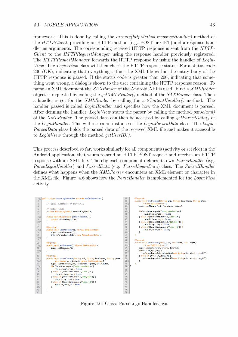
4.1. MOBILE APPLICATION 43
framework. This is done by calling the execute(httpMethod,responseHandler) method ofthe HTTPClient, providing an HTTP method (e.g. POST or GET) and a response han-dler as arguments. The corresponding received HTTP response is sent from the HTTP-Client to the HTTPRequestManager using the response handler previously registered.The HTTPRequestManager forwards the HTTP response by using the handler of Login-View. The LoginView class will then check the HTTP response status. For a status code200 (OK), indicating that everything is fine, the XML file within the entity body of theHTTP response is parsed. If the status code is greater than 200, indicating that some-thing went wrong, a dialog is shown to the user containing the HTTP response reason. Toparse an XML document the SAXParser of the Android API is used. First a XMLReaderobject is requested by calling the getXMLReader() method of the SAXParser class. Thena handler is set for the XMLReader by calling the setContentHandler() method. Thehandler passed is called LoginHandler and specifies how the XML document is parsed.After defining the handler, LoginView starts the parser by calling the method parse(xml)of the XMLReader. The parsed data can then be accessed by calling getParsedData() ofthe LoginHandler. This will return an instance of the LoginParsedData class. The Login-ParsedData class holds the parsed data of the received XML file and makes it accessibleto LoginView through the method getUserID().
This process described so far, works similarly for all components (activity or service) in theAndroid application, that wants to send an HTTP POST request and receives an HTTPresponse with an XML file. Thereby each component defines its own ParseHandler (e.g.ParseLoginHandler) and ParsedData (e.g. ParsedLoginData) class. The ParsedHandlerdefines what happens when the XMLParser encounters an XML element or character inthe XML file. Figure 4.6 shows how the ParseHandler is implemented for the LoginViewactivity.
Figure 4.6: Class: ParseLoginHandler.java
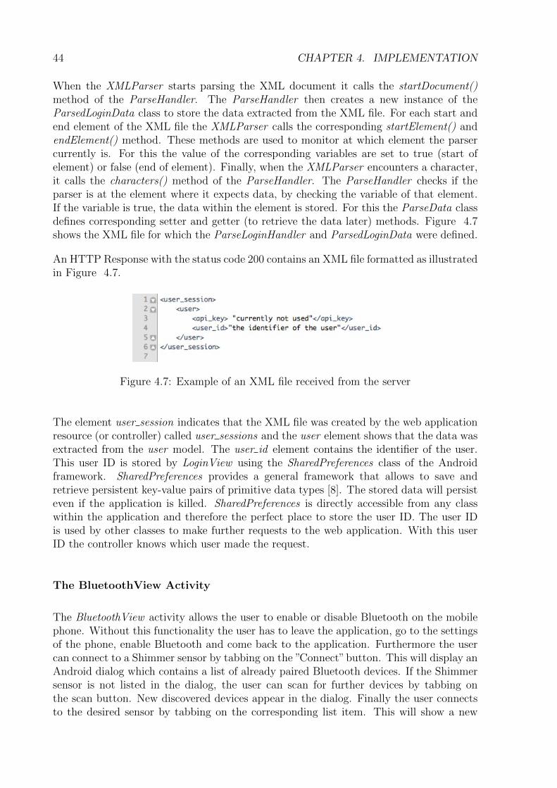
44 CHAPTER 4. IMPLEMENTATION
When the XMLParser starts parsing the XML document it calls the startDocument()method of the ParseHandler. The ParseHandler then creates a new instance of theParsedLoginData class to store the data extracted from the XML file. For each start andend element of the XML file the XMLParser calls the corresponding startElement() andendElement() method. These methods are used to monitor at which element the parsercurrently is. For this the value of the corresponding variables are set to true (start ofelement) or false (end of element). Finally, when the XMLParser encounters a character,it calls the characters() method of the ParseHandler. The ParseHandler checks if theparser is at the element where it expects data, by checking the variable of that element.If the variable is true, the data within the element is stored. For this the ParseData classdefines corresponding setter and getter (to retrieve the data later) methods. Figure 4.7shows the XML file for which the ParseLoginHandler and ParsedLoginData were defined.
An HTTP Response with the status code 200 contains an XML file formatted as illustratedin Figure 4.7.
Figure 4.7: Example of an XML file received from the server
The element user session indicates that the XML file was created by the web applicationresource (or controller) called user sessions and the user element shows that the data wasextracted from the user model. The user id element contains the identifier of the user.This user ID is stored by LoginView using the SharedPreferences class of the Androidframework. SharedPreferences provides a general framework that allows to save andretrieve persistent key-value pairs of primitive data types [8]. The stored data will persisteven if the application is killed. SharedPreferences is directly accessible from any classwithin the application and therefore the perfect place to store the user ID. The user IDis used by other classes to make further requests to the web application. With this userID the controller knows which user made the request.
The BluetoothView Activity
The BluetoothView activity allows the user to enable or disable Bluetooth on the mobilephone. Without this functionality the user has to leave the application, go to the settingsof the phone, enable Bluetooth and come back to the application. Furthermore the usercan connect to a Shimmer sensor by tabbing on the ”Connect”button. This will display anAndroid dialog which contains a list of already paired Bluetooth devices. If the Shimmersensor is not listed in the dialog, the user can scan for further devices by tabbing onthe scan button. New discovered devices appear in the dialog. Finally the user connectsto the desired sensor by tabbing on the corresponding list item. This will show a new
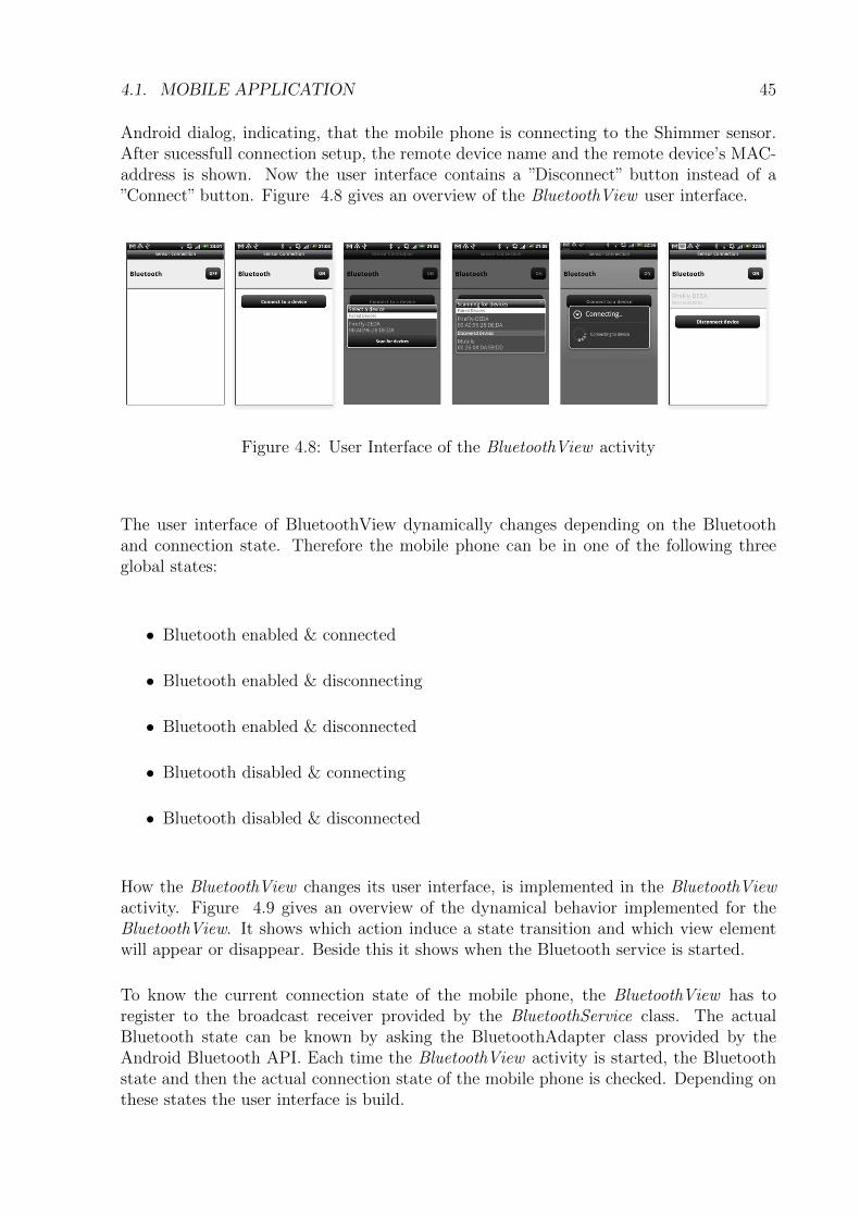
4.1. MOBILE APPLICATION 45
Android dialog, indicating, that the mobile phone is connecting to the Shimmer sensor.After sucessfull connection setup, the remote device name and the remote device’s MAC-address is shown. Now the user interface contains a ”Disconnect” button instead of a”Connect” button. Figure 4.8 gives an overview of the BluetoothView user interface.
Figure 4.8: User Interface of the BluetoothView activity
The user interface of BluetoothView dynamically changes depending on the Bluetoothand connection state. Therefore the mobile phone can be in one of the following threeglobal states:
• Bluetooth enabled & connected
• Bluetooth enabled & disconnecting
• Bluetooth enabled & disconnected
• Bluetooth disabled & connecting
• Bluetooth disabled & disconnected
How the BluetoothView changes its user interface, is implemented in the BluetoothViewactivity. Figure 4.9 gives an overview of the dynamical behavior implemented for theBluetoothView. It shows which action induce a state transition and which view elementwill appear or disappear. Beside this it shows when the Bluetooth service is started.
To know the current connection state of the mobile phone, the BluetoothView has toregister to the broadcast receiver provided by the BluetoothService class. The actualBluetooth state can be known by asking the BluetoothAdapter class provided by theAndroid Bluetooth API. Each time the BluetoothView activity is started, the Bluetoothstate and then the actual connection state of the mobile phone is checked. Depending onthese states the user interface is build.
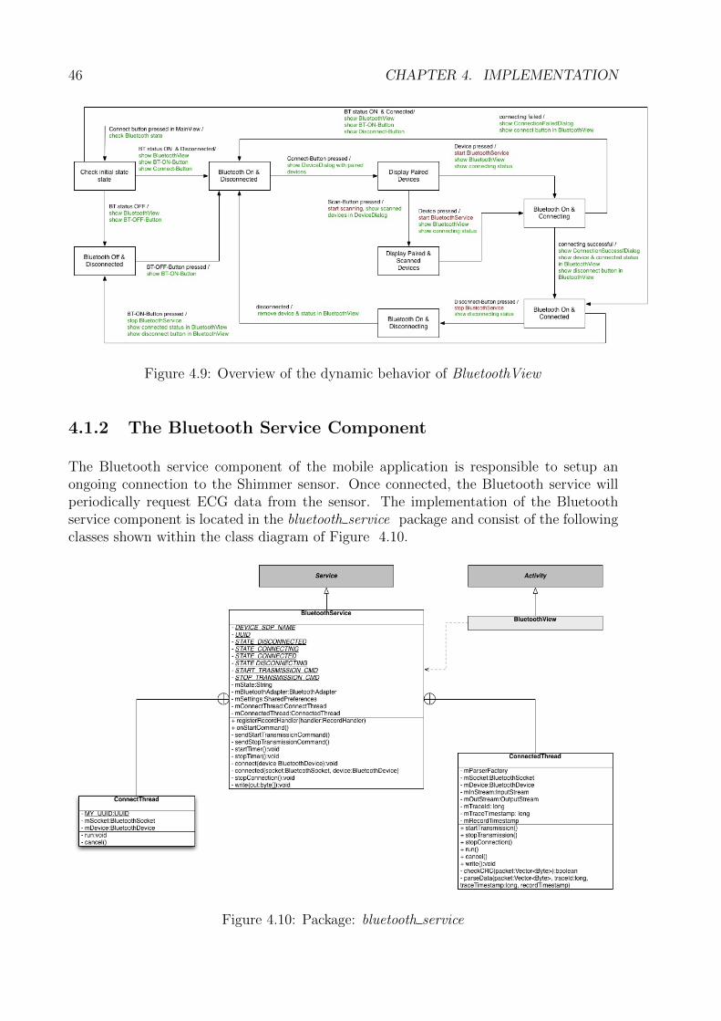
46 CHAPTER 4. IMPLEMENTATION
Figure 4.9: Overview of the dynamic behavior of BluetoothView
4.1.2 The Bluetooth Service Component
The Bluetooth service component of the mobile application is responsible to setup anongoing connection to the Shimmer sensor. Once connected, the Bluetooth service willperiodically request ECG data from the sensor. The implementation of the Bluetoothservice component is located in the bluetooth service package and consist of the followingclasses shown within the class diagram of Figure 4.10.
Figure 4.10: Package: bluetooth service
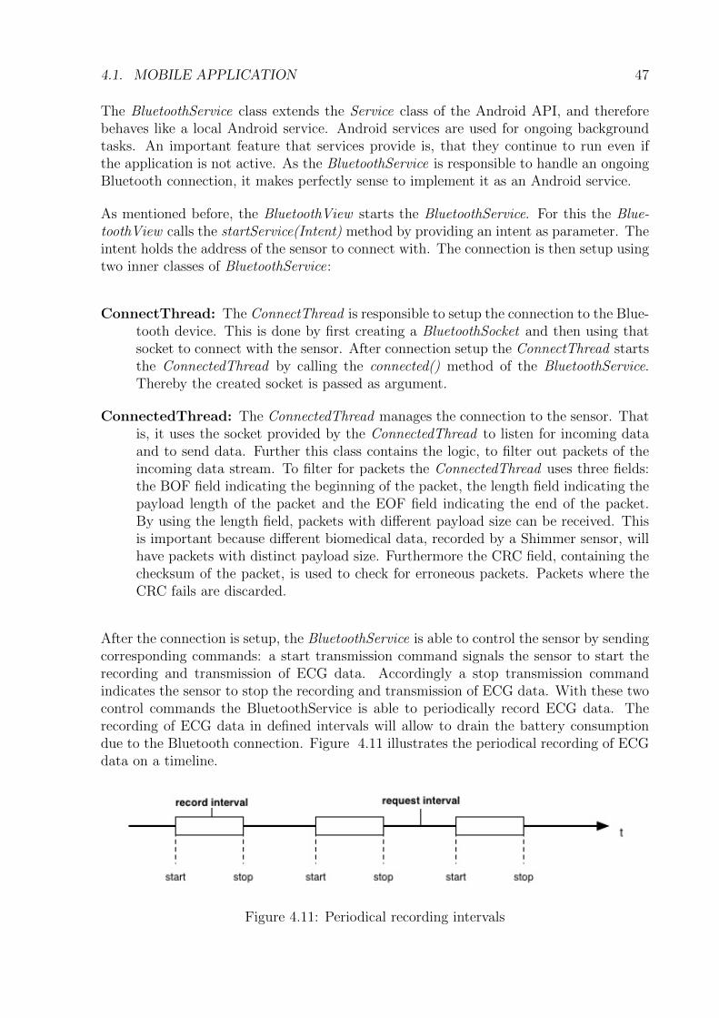
4.1. MOBILE APPLICATION 47
The BluetoothService class extends the Service class of the Android API, and thereforebehaves like a local Android service. Android services are used for ongoing backgroundtasks. An important feature that services provide is, that they continue to run even ifthe application is not active. As the BluetoothService is responsible to handle an ongoingBluetooth connection, it makes perfectly sense to implement it as an Android service.
As mentioned before, the BluetoothView starts the BluetoothService. For this the Blue-toothView calls the startService(Intent) method by providing an intent as parameter. Theintent holds the address of the sensor to connect with. The connection is then setup usingtwo inner classes of BluetoothService:
ConnectThread: The ConnectThread is responsible to setup the connection to the Blue-tooth device. This is done by first creating a BluetoothSocket and then using thatsocket to connect with the sensor. After connection setup the ConnectThread startsthe ConnectedThread by calling the connected() method of the BluetoothService.Thereby the created socket is passed as argument.
ConnectedThread: The ConnectedThread manages the connection to the sensor. Thatis, it uses the socket provided by the ConnectedThread to listen for incoming dataand to send data. Further this class contains the logic, to filter out packets of theincoming data stream. To filter for packets the ConnectedThread uses three fields:the BOF field indicating the beginning of the packet, the length field indicating thepayload length of the packet and the EOF field indicating the end of the packet.By using the length field, packets with different payload size can be received. Thisis important because different biomedical data, recorded by a Shimmer sensor, willhave packets with distinct payload size. Furthermore the CRC field, containing thechecksum of the packet, is used to check for erroneous packets. Packets where theCRC fails are discarded.
After the connection is setup, the BluetoothService is able to control the sensor by sendingcorresponding commands: a start transmission command signals the sensor to start therecording and transmission of ECG data. Accordingly a stop transmission commandindicates the sensor to stop the recording and transmission of ECG data. With these twocontrol commands the BluetoothService is able to periodically record ECG data. Therecording of ECG data in defined intervals will allow to drain the battery consumptiondue to the Bluetooth connection. Figure 4.11 illustrates the periodical recording of ECGdata on a timeline.
Figure 4.11: Periodical recording intervals
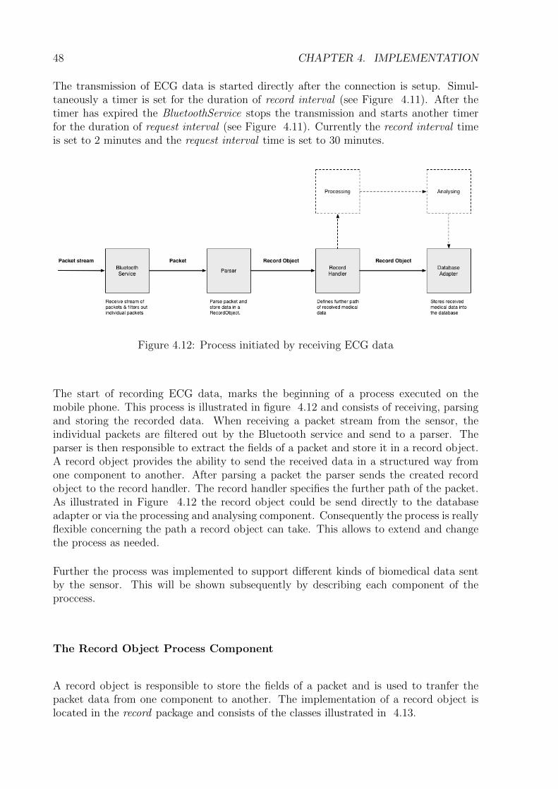
48 CHAPTER 4. IMPLEMENTATION
The transmission of ECG data is started directly after the connection is setup. Simul-taneously a timer is set for the duration of record interval (see Figure 4.11). After thetimer has expired the BluetoothService stops the transmission and starts another timerfor the duration of request interval (see Figure 4.11). Currently the record interval timeis set to 2 minutes and the request interval time is set to 30 minutes.
Figure 4.12: Process initiated by receiving ECG data
The start of recording ECG data, marks the beginning of a process executed on themobile phone. This process is illustrated in figure 4.12 and consists of receiving, parsingand storing the recorded data. When receiving a packet stream from the sensor, theindividual packets are filtered out by the Bluetooth service and send to a parser. Theparser is then responsible to extract the fields of a packet and store it in a record object.A record object provides the ability to send the received data in a structured way fromone component to another. After parsing a packet the parser sends the created recordobject to the record handler. The record handler specifies the further path of the packet.As illustrated in Figure 4.12 the record object could be send directly to the databaseadapter or via the processing and analysing component. Consequently the process is reallyflexible concerning the path a record object can take. This allows to extend and changethe process as needed.
Further the process was implemented to support different kinds of biomedical data sentby the sensor. This will be shown subsequently by describing each component of theproccess.
The Record Object Process Component
A record object is responsible to store the fields of a packet and is used to tranfer thepacket data from one component to another. The implementation of a record object islocated in the record package and consists of the classes illustrated in 4.13.
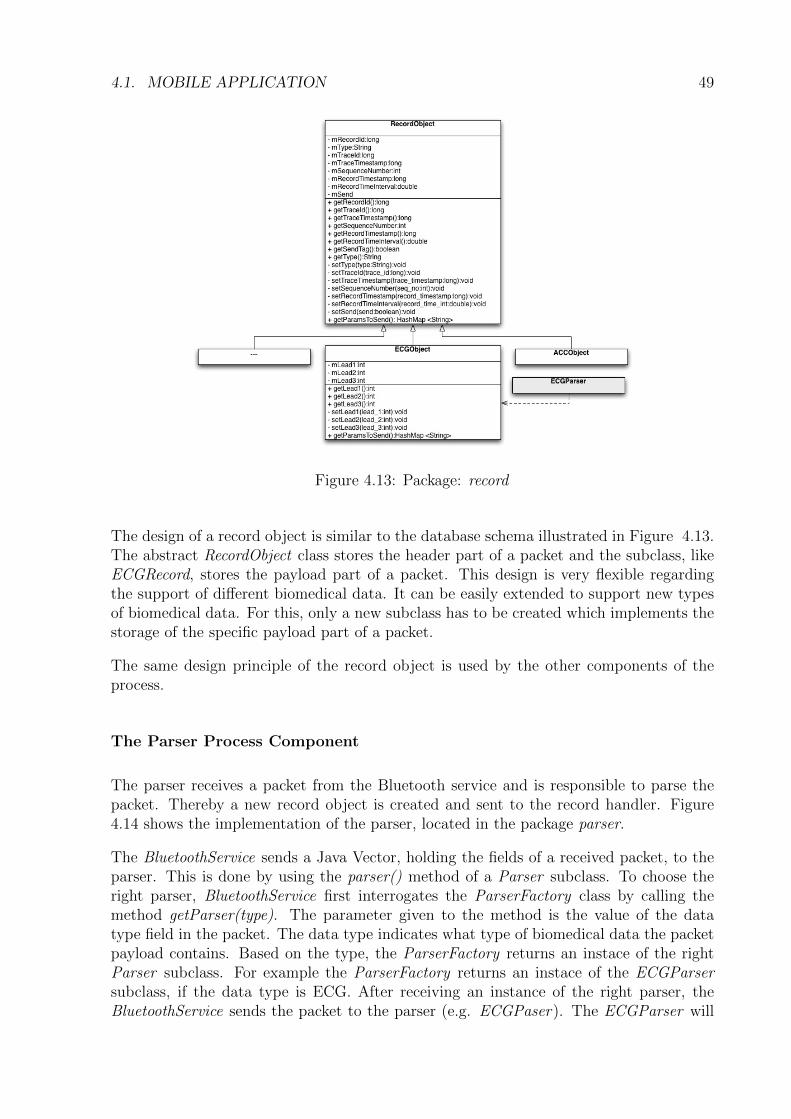
4.1. MOBILE APPLICATION 49
Figure 4.13: Package: record
The design of a record object is similar to the database schema illustrated in Figure 4.13.The abstract RecordObject class stores the header part of a packet and the subclass, likeECGRecord, stores the payload part of a packet. This design is very flexible regardingthe support of different biomedical data. It can be easily extended to support new typesof biomedical data. For this, only a new subclass has to be created which implements thestorage of the specific payload part of a packet.
The same design principle of the record object is used by the other components of theprocess.
The Parser Process Component
The parser receives a packet from the Bluetooth service and is responsible to parse thepacket. Thereby a new record object is created and sent to the record handler. Figure4.14 shows the implementation of the parser, located in the package parser.
The BluetoothService sends a Java Vector, holding the fields of a received packet, to theparser. This is done by using the parser() method of a Parser subclass. To choose theright parser, BluetoothService first interrogates the ParserFactory class by calling themethod getParser(type). The parameter given to the method is the value of the datatype field in the packet. The data type indicates what type of biomedical data the packetpayload contains. Based on the type, the ParserFactory returns an instace of the rightParser subclass. For example the ParserFactory returns an instace of the ECGParsersubclass, if the data type is ECG. After receiving an instance of the right parser, theBluetoothService sends the packet to the parser (e.g. ECGPaser). The ECGParser will
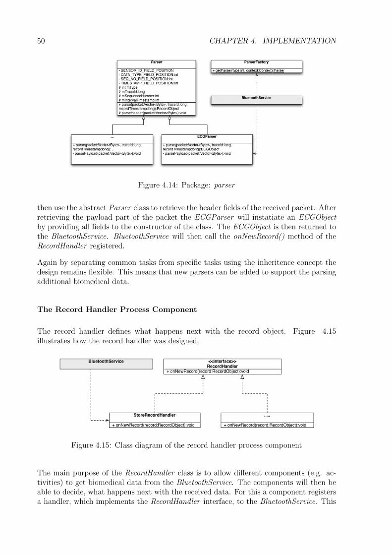
50 CHAPTER 4. IMPLEMENTATION
Figure 4.14: Package: parser
then use the abstract Parser class to retrieve the header fields of the received packet. Afterretrieving the payload part of the packet the ECGParser will instatiate an ECGObjectby providing all fields to the constructor of the class. The ECGObject is then returned tothe BluetoothService. BluetoothService will then call the onNewRecord() method of theRecordHandler registered.
Again by separating common tasks from specific tasks using the inheritence concept thedesign remains flexible. This means that new parsers can be added to support the parsingadditional biomedical data.
The Record Handler Process Component
The record handler defines what happens next with the record object. Figure 4.15illustrates how the record handler was designed.
Figure 4.15: Class diagram of the record handler process component
The main purpose of the RecordHandler class is to allow different components (e.g. ac-tivities) to get biomedical data from the BluetoothService. The components will then beable to decide, what happens next with the received data. For this a component registersa handler, which implements the RecordHandler interface, to the BluetoothService. This
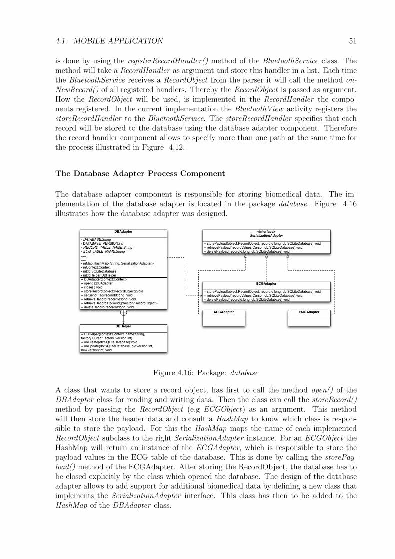
4.1. MOBILE APPLICATION 51
is done by using the registerRecordHandler() method of the BluetoothService class. Themethod will take a RecordHandler as argument and store this handler in a list. Each timethe BluetoothService receives a RecordObject from the parser it will call the method on-NewRecord() of all registered handlers. Thereby the RecordObject is passed as argument.How the RecordObject will be used, is implemented in the RecordHandler the compo-nents registered. In the current implementation the BluetoothView activity registers thestoreRecordHandler to the BluetoothService. The storeRecordHandler specifies that eachrecord will be stored to the database using the database adapter component. Thereforethe record handler component allows to specify more than one path at the same time forthe process illustrated in Figure 4.12.
The Database Adapter Process Component
The database adapter component is responsible for storing biomedical data. The im-plementation of the database adapter is located in the package database. Figure 4.16illustrates how the database adapter was designed.
Figure 4.16: Package: database
A class that wants to store a record object, has first to call the method open() of theDBAdapter class for reading and writing data. Then the class can call the storeRecord()method by passing the RecordObject (e.g ECGObject) as an argument. This methodwill then store the header data and consult a HashMap to know which class is respon-sible to store the payload. For this the HashMap maps the name of each implementedRecordObject subclass to the right SerializationAdapter instance. For an ECGObject theHashMap will return an instance of the ECGAdapter, which is responsible to store thepayload values in the ECG table of the database. This is done by calling the storePay-load() method of the ECGAdapter. After storing the RecordObject, the database has tobe closed explicitly by the class which opened the database. The design of the databaseadapter allows to add support for additional biomedical data by defining a new class thatimplements the SerializationAdapter interface. This class has then to be added to theHashMap of the DBAdapter class.
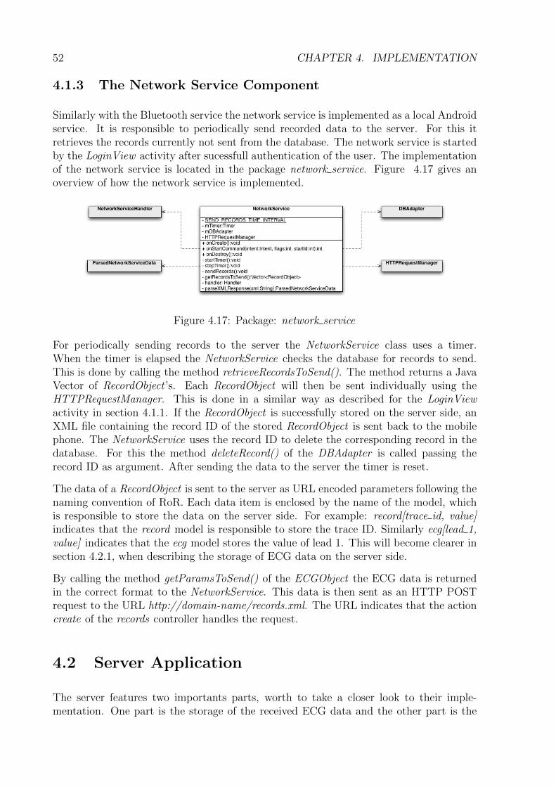
52 CHAPTER 4. IMPLEMENTATION
4.1.3 The Network Service Component
Similarly with the Bluetooth service the network service is implemented as a local Androidservice. It is responsible to periodically send recorded data to the server. For this itretrieves the records currently not sent from the database. The network service is startedby the LoginView activity after sucessfull authentication of the user. The implementationof the network service is located in the package network service. Figure 4.17 gives anoverview of how the network service is implemented.
Figure 4.17: Package: network service
For periodically sending records to the server the NetworkService class uses a timer.When the timer is elapsed the NetworkService checks the database for records to send.This is done by calling the method retrieveRecordsToSend(). The method returns a JavaVector of RecordObject ’s. Each RecordObject will then be sent individually using theHTTPRequestManager. This is done in a similar way as described for the LoginViewactivity in section 4.1.1. If the RecordObject is successfully stored on the server side, anXML file containing the record ID of the stored RecordObject is sent back to the mobilephone. The NetworkService uses the record ID to delete the corresponding record in thedatabase. For this the method deleteRecord() of the DBAdapter is called passing therecord ID as argument. After sending the data to the server the timer is reset.
The data of a RecordObject is sent to the server as URL encoded parameters following thenaming convention of RoR. Each data item is enclosed by the name of the model, whichis responsible to store the data on the server side. For example: record[trace id, value]indicates that the record model is responsible to store the trace ID. Similarly ecg[lead 1,value] indicates that the ecg model stores the value of lead 1. This will become clearer insection 4.2.1, when describing the storage of ECG data on the server side.
By calling the method getParamsToSend() of the ECGObject the ECG data is returnedin the correct format to the NetworkService. This data is then sent as an HTTP POSTrequest to the URL http://domain-name/records.xml. The URL indicates that the actioncreate of the records controller handles the request.
4.2 Server Application
The server features two importants parts, worth to take a closer look to their imple-mentation. One part is the storage of the received ECG data and the other part is the
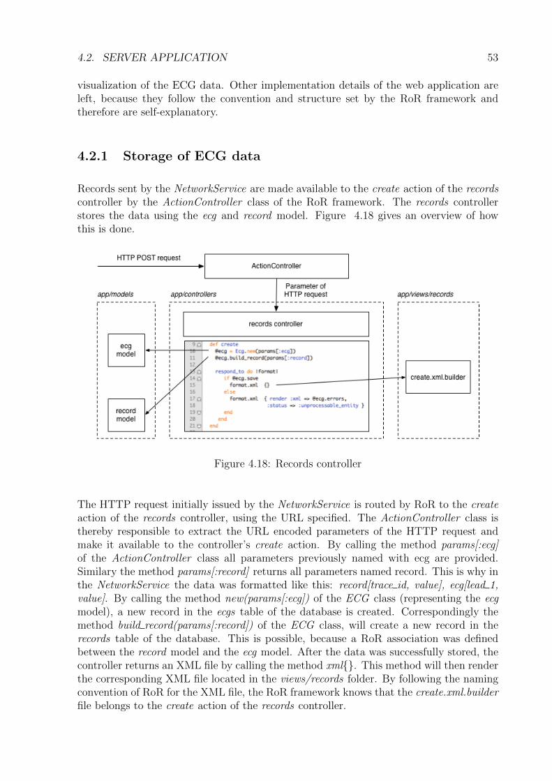
4.2. SERVER APPLICATION 53
visualization of the ECG data. Other implementation details of the web application areleft, because they follow the convention and structure set by the RoR framework andtherefore are self-explanatory.
4.2.1 Storage of ECG data
Records sent by the NetworkService are made available to the create action of the recordscontroller by the ActionController class of the RoR framework. The records controllerstores the data using the ecg and record model. Figure 4.18 gives an overview of howthis is done.
Figure 4.18: Records controller
The HTTP request initially issued by the NetworkService is routed by RoR to the createaction of the records controller, using the URL specified. The ActionController class isthereby responsible to extract the URL encoded parameters of the HTTP request andmake it available to the controller’s create action. By calling the method params[:ecg]of the ActionController class all parameters previously named with ecg are provided.Similary the method params[:record] returns all parameters named record. This is why inthe NetworkService the data was formatted like this: record[trace id, value], ecg[lead 1,value]. By calling the method new(params[:ecg]) of the ECG class (representing the ecgmodel), a new record in the ecgs table of the database is created. Correspondingly themethod build record(params[:record]) of the ECG class, will create a new record in therecords table of the database. This is possible, because a RoR association was definedbetween the record model and the ecg model. After the data was successfully stored, thecontroller returns an XML file by calling the method xml{}. This method will then renderthe corresponding XML file located in the views/records folder. By following the namingconvention of RoR for the XML file, the RoR framework knows that the create.xml.builderfile belongs to the create action of the records controller.
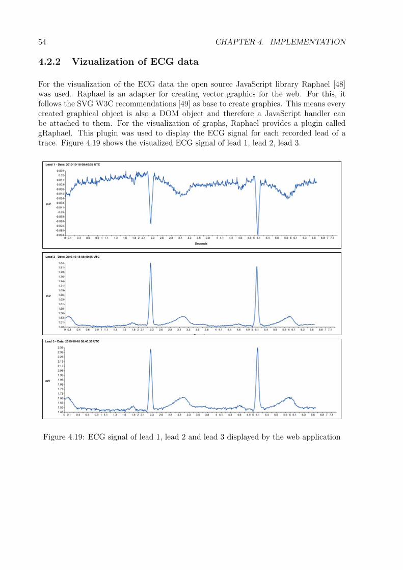
54 CHAPTER 4. IMPLEMENTATION
4.2.2 Vizualization of ECG data
For the visualization of the ECG data the open source JavaScript library Raphael [48]was used. Raphael is an adapter for creating vector graphics for the web. For this, itfollows the SVG W3C recommendations [49] as base to create graphics. This means everycreated graphical object is also a DOM object and therefore a JavaScript handler canbe attached to them. For the visualization of graphs, Raphael provides a plugin calledgRaphael. This plugin was used to display the ECG signal for each recorded lead of atrace. Figure 4.19 shows the visualized ECG signal of lead 1, lead 2, lead 3.
Figure 4.19: ECG signal of lead 1, lead 2 and lead 3 displayed by the web application
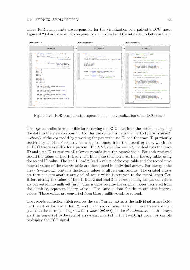
4.2. SERVER APPLICATION 55
Three RoR components are responsible for the visualization of a patient’s ECG trace.Figure 4.20 illustrates which components are involved and the interactions between them.
Figure 4.20: RoR components responsible for the visualization of an ECG trace
The ecgs controller is responsible for retrieving the ECG data from the model and passingthe data to the view component. For this the controller calls the method fetch recordedvalues() of the ecg model by providing the patient’s user ID and the trace ID previously
received by an HTTP request. This request comes from the preceding view, which listall ECG traces available for a patient. The fetch recorded values() method uses the traceID and user ID to retrieve all relevant records from the records table. For each retrievedrecord the values of lead 1, lead 2 and lead 3 are then retrieved from the ecg table, usingthe record ID value. The lead 1, lead 2, lead 3 values of the ecgs table and the record timeinterval values of the records table are then stored in individual arrays. For example thearray temp lead 1 contains the lead 1 values of all relevant records. The created arraysare then put into another array called result which is returned to the records controller.Before storing the values of lead 1, lead 2 and lead 3 in corresponding arrays, the valuesare converted into millivolt (mV). This is done because the original values, retrieved fromthe database, represent binary values. The same is done for the record time intervalvalues. These values are converted from binary milliseconds to seconds.
The records controller which receives the result array, extracts the individual arrays hold-ing the values for lead 1, lead 2, lead 3 and record time interval. These arrays are thenpassed to the corresponding view file (show.html.erb). In the show.html.erb file the arraysare then converted to JavaScript arrays and inserted in the JavaScript code, responsibleto display the ECG signal.
56 CHAPTER 4. IMPLEMENTATION
Chapter 5
Future Work
The mobile healthcare system described in the last two chapters can be extended indifferent ways to support additional functionalities. This chapter aims to present somefuture work that could be done for the mobile healthcare system.
Three fields have been identified and could be the subject of further development:
• Processing and analysis of ECG data.
• Continously monitoring of ECG data in real time.
• Recording of additional biomedical data and environmental data.
Subsequently these three fields will be described briefly. After that some more fine grainedenhancements concerning the mobile and server application will be presented.
Processing and analysis of ECG data
The server could be extended to include an analyzing module for the recorded ECGdata. This could consist of recognizing the recurrent wave sequence of P-, QRS- and T-wave associated with each heart beat [47]. Especially the recognition of the RR intervaland the QRS complex reveal crucial heart condition of a monitored patient [46]. Manydifferent methods have been developed the past thirty years for detecting and classifyingthese features of an ECG signal [57]. Based on the categorization of the recognizedfeatures an automated cardiac desease diagnosis is possible, supporting the doctors in theinterpretation fo the ECG signal. Furthermore the automatic detection of abnormalitiescould be used to notify the patient and doctors if a severe health condition occurs.
The analyzing module could also include the extraction of information not readily availablefrom the signal throught visual assessment [58]. For example the RR-interval could beused to calculate the heart rate of a patient [35].
57
58 CHAPTER 5. FUTURE WORK
Continously monitoring of ECG data in real time
The whole system could be improved to allow a continously monitoring of ECG data. Thatmeans the acquired data is send continuously from the sensor over the Android mobilephone to the server. At the present time the ECG data is recorded only periodically.Therefore the doctor looking at the ECG signal does not see the most recent ECG ofthe patient. As the condition of the heart can rapidly change, this will be an importantextension to the described mobile healthcare system.
Support of further biomedical and environmental data
The presented system could be improved to support the recording of futher biomedicaldata of a patient. As mentioned in section 2.3 the Shimmer platform provides severalsensing capabilities like EMG, Gyroboard and so on. Regarding the communication ca-pabilities of the Shimmer sensor it could be even possible to form a body area networkof these sensors, each sensor recording specific biomedical data. The different recordedbiomedical data could then be combined in the analysis of the patients health.
Beside recording biomedical data using a sensor, the mobile phone could be used to recordthe location of the patient using GPS. This allows a wide range of new possibilities. Forexample the recorded location data could be used to retrieve information about the envi-ronment of the patient’s location. This could include current temperature and pollutionextracted from a weather database. Further the pace at which the patient moved can berelated to the recorded ECG data and the thereby derived heart rate.
Extending the mobile application and server application
The server application could be extendend to provide further web services. Currentlythe mobile application only communicates with the web application to authenticate andsend medical data to the server. Both, the server application and the mobile applicationcould be extended to provide further functionalities for the user on the mobile phone. Thesubsequent list describes some functionalities that could be implemented.
• Allow the user to register an account on the web application from the mobile phone.
• Allow the user to see its ECG trace on the mobile phone.
• Allow the user to see, edit and update its personal data stored on the web server.
Moreover the mobile application could be extended to provide a remote Bluetooth service.This means that other applications can use the Bluetooth service to connect to a Shimmersensor and record biomedical data. At present time the Bluetooth service component isimplemented as a local Android service. Therefore the Bluetooth service can only be usedwhithin the application. But the current implementation of the Bluetooth service caneasily be extended to a remote service. To do this, an interface has to be implemented to
59
allow other applications to communicate with the Bluetooth service. This is done by usingthe Android Interface Definition Language (AIDL). This interface definition language isused to generate code that enables two processes on a Android mobile device to talkusing interprocess communication (IPC) [12]. By allowing other applications to use theBluetooth service, a platform of different applications may be thinkable. Each applicationdesignated to fulfil a specific task.
60 CHAPTER 5. FUTURE WORK
Chapter 6
Summary and Conclusions
With the emergence of sophisticated wearable sensors and the advances in mobile com-munication , new opportunities open up for developing mobile healthcare systems whichmonitor biomedical signals from patients. Especially the continuous, or even sporadicrecording of ECG signals, will improve the diagnosis and treatment of cardiovascular de-seases by allowing a more realistic view on the patients’ health condition. Driven bythese opportunities, sophisticated mobile healtcare systems will certainly arise in the nearfuture, supporting and enhancing today’s provided healthcare services.
The goal of this thesis was to implement and design a prototype mobile healthcare systemconsisting of three parts: a Shimmer sensor that records ECG data from a patient inreal-time, an Android mobile phone that forwards the received data from the sensor to acentral server and finally a server responsible to store and display the recorded ECG data.Thereby, the system shall allow basic medical assessment of patients by their doctors. Twomain requirements were defined for the system. First, the mobile healthcare applicationshould allow the seamless transmission of the recorded data from the sensor to the server.Secondly, the system has to be designed in a way to be flexible enough in order to supportvarious types of biomedical and environmental data.
At the end, a prototype mobile healthcare system was provided that features the mainrequirements defined. The system developed has the ability to periodically record theECG of a patient and send it over an Android mobile phone to a central server. Thepatient and his doctors are then able to see the recorded ECG signal by accessing theweb application. Further doctors can write a diagnosis in form of a comment under theECG displayed, which allows basic medical assement of patients. For the implementationof the web application the Ruby on Rails framework was chosen. The main reason forchoosing Ruby on Rails was, that it allows the fast development of a web applicationby putting convention over configuration and provides a straightforward structure for theweb application. The overall system was designed in such a way that it can be extendedregarding the support of other types of biomedical and environmental data.
With this extensibility to various types of biomedical data, the presented prototype mobilehealthcare system provides a solid base for further extensions or the development of a newsystem.
61
62 CHAPTER 6. SUMMARY AND CONCLUSIONS
Bibliography
[1] Electrocardiography - Wikipedia: the free encyclopedia, http://en.wikipedia.org/wiki/Electrocardiography, 12th Oct. 2010.
[2] Anwar Vahed: 3-Lead Wireless ECG, http://www.open-ecg-project.org/tiki-index.php?page=3-Lead+Wireless+ECG, 15th Nov. 2005.
[3] M. C. Mancini: Heart Anatomy, http://emedicine.medscape.com/article/905502-overview, last visited 7th Oct. 2008.
[4] Open Handset Alliance, http://www.openhandsetalliance.com/, last visited 21thOct. 2010.
[5] Alliance Overview - Open Handset Alliance, http://www.openhandsetalliance.com/oha overview.html, last visited 21. Oct. 2010.
[6] Android Overview - Open Handset Alliance, http://www.openhandsetalliance.com/android overview.html, last visited 22th Oct. 2010.
[7] What is Android? - Android Developers, http://developer.android.com/guide/basics/what-is-android.html, last visited 21th Oct. 2010.
[8] Data Storage - Android Developers, http://developer.android.com/guide/topics/data/data-storage.html#db, last visited 21th Oct. 2010.
[9] Android Fundamentals - Android Developers, http://developer.android.com/guide/topics/fundamentals.html, last visited 21th Oct. 2010.
[10] Bluetooth - Android Developers, http://developer.android.com/guide/topics/wireless/bluetooth.html, last visited 10th Oct. 2010.
[11] User Interface - Android Developers, http://developer.android.com/guide/topics/ui/index.html, last visited 10th Oct. 2010.
[12] Designing a Remote Interface - Android Developers, http://developer.android.com/guide/developing/tools/aidl.html, last visited 15th Oct. 2010.
[13] E. Burnette: Hello Android - Introducing Google’s Mobile Development Platform,The Pragmatic Bookshelf, 2008.
[14] R. Meier: Professional Android 2 Application Development, Wiley Publishing Inc,2010.
63
64 BIBLIOGRAPHY
[15] S. Hashimi, S. Komatineni, D. MacLean: Pro Android 2, Apress, 2010.
[16] Ruby on Rails, http://rubyonrails.org/, last visited 10th Oct. 2010.
[17] R. T. Fielding: Architectural Styles and the Design of Network-based Software Ar-chitectures, http://www.ics.uci.edu/ fielding/pubs/dissertation/top.htm, last visited10th Oct. 2010.
[18] Ruby Programming Language, http://www.ruby-lang.org/en/, last visited 10th Oct.2010.
[19] Ruby on Rails: Getting Started with Rails, http://guides.rubyonrails.org/gettingstarted.html, last visited 22th Oct. 2010.
[20] J. Williams: Rails Solutions: Ruby on Rails Made Easy, friendsof, 2007.
[21] L. Richardson, S. Ruby: RESTful Web Services, O’Reilly Media, 2007.
[22] Shimmer - Wireless Sensor Platform for Wearable Applications, http://www.shimmer-research.com/, last visited 23th Oct. 2010.
[23] Wireless Sensor Technology (WSN/BSN), Pervasive / Ubiquitous Computing - Shim-mer Platform, http://www.shimmer-research.com/r-d, last visited 23th Oct. 2010.
[24] Wireless Sensor - Shimmer Expansion Modules, http://www.shimmer-research.com/r-d/platform-features, last visited 23th Oct. 2010.
[25] Wearable Wireless Sensor Platform - About Shimmer Research, http://www.shimmer-research.com/about, last visited 23th Oct. 2010.
[26] Shimmer Platform - Key Features, http://www.shimmer-research.com/r-d/platform-features, last visited 20th Nov. 2010.
[27] MSP430 16-bit Ultra-Low Power (MCU), Low Power Mixed Signal Processors,http://focus.ti.com/mcu/docs/mcuprodoverview.tsp?sectionId=95&tabId=140&familyId=342, last visited 20th Oct. 2010.
[28] TinyOS webpage, http://www.tinyos.net/, last visited 20th Oct. 2010.
[29] nesC: A programming Language for Deeply Networked Systems, http://nescc.sourceforge.net/, last visited 21th Oct. 2010.
[30] Y. Hao, R. Foster: Wireless body sensor networks for health-monitoring applications,Physiological measurement, Vol. 29, pp. 27-56, 2008.
[31] A.Burns, B. R. Greene et al: SHIMMER - A Wireless Sensor Platform for NoninvasiveBiomedical Research, IEEE Sensors Journal, Vol. 10, No.9, pp. 1527-1534, 2009.
[32] M. J. McGrath, T. J. Dishongh: A Common Personal Health Research Platform -Shimmer and BioMobius, Intel Technology Journal, Vol. 13, Issue 3, pp. 122-147,2009.
BIBLIOGRAPHY 65
[33] M. McGrath, T. J. Dishongh: SHIMMER and BioMOBIUS: A Health Research Plat-form, http://www.drdobbs.com/embedded-systems/221700058;jsessionid=CW1P52YTUDTMVQE1GHPSKHWATMY32JVN, last visited 13th Oct. 2010.
[34] SourceForge.net Respository - tinyos-1.x, http://tinyos.cvs.sourceforge.net/viewvc/tinyos/tinyos-1.x/, last visited 23th Oct. 2010.
[35] An ECG Primer, http://www.nursecom.com/ECGprimer.pdf, last visited 13th Oct.2010.
[36] J. Lee: ECG Monitoring in Theatre, http://www.nda.ox.ac.uk/wfsa/html/u11/u1105 01.htm, last visited 5th Oct. 2010.
[37] The ECG Waveform, http://sprojects.mmi.mcgill.ca/cardiophysio/EKGQTinterval.htm, last visited 25th Oct. 2010.
[38] Home | TRIL, http://www.trilcentre.org/, last visited 27th Oct. 2010.
[39] BioMobious ECG application for Shimmer, http://tinyos.cvs.sourceforge.net/viewvc/tinyos/tinyos-1.x/contrib/handhelds/apps/BioMOBIUS/ECG/, last visited 27thOct. 2010.
[40] TRIL | BioMobious, http://www.trilcentre.org/technology-design/tril-technologies/biomobius.html, last visited 27th Oct. 2010.
[41] SQLite Home Page, http://www.sqlite.org/, last visited 5th Oct. 2010.
[42] MySQL: The world’s most popular open source database, last visited 9th Oct. 2010.
[43] rail’s ssl requirement at master - GitHub, http://github.com/rails/ssl requirement,last visited 29th Oct. 2010.
[44] binarylogic’s authlogic at master - GitHub, http://github.com/binarylogic/authlogic#readme, last visited 29th Oct. 2010.
[45] stffn’s declarative authorization at master - GitHub, http://github.com/stffn/declarative authorization, last visited 29th Oct. 2010.
[46] F.Sufi, Q. Fang, I. Cosic: ECG R-R Peak Detection on Mobile Phones, Proceedingsof the 29th Annual International Conference of the IEEE EMBS, pp. 3697-3700, 2007.
[47] Review of Data analysis methods for Denoising and Characterizing ECG,http://cnx.org/content/m32823/1.1/, last visited 14th Oct. 2010.
[48] Raphael Java Script Libray, http://raphaeljs.com/, last visited 30th Oct. 2010.
[49] W3C Scalable Vector Graphics (SVG) 1.1 Specification, http://www.w3.org/TR/2003/REC-SVG11-20030114/, last visited 14th Oct. 2010.
[50] H. Kew, D. Jeong, Wearable Patch-type ECG using Ubiquitous Wireless Sensor Net-work for Healthcare Monitoring Application, ICIS, 2009.
66 BIBLIOGRAPHY
[51] P. F. Binkley, W. Frontera, D.G. Standaert, J.Stein, Predicting the Potential ofWearable Technology, IEEE engineering in medicine and biology magazine, Vol. 22,pp. 23-27, 2003.
[52] The electrocardiogram - looking at the heart of electricity, http://nobelprize.org/educational/medicine/ecg/ecg-readmore.html, last visited 30th Oct. 2010.
[53] J. Penders, J. Molengraft, L. Brown et al.: Potential and challenges of Body AreaNetworks for personal health, 31st Annual International Conference of the IEEEEMBS, pp. 6569-6572, 2009.
[54] B. Gyselinckx, Ph. Mattelaer, R. Borzi: ”Human++: emerging technology for BodyArea Networks”, in Brave New Interfaces. Individual, Social and Economic Impactof the Next Generation Interfaces, Crosstalks, 2007.
[55] W. Chung, C. Yau, K. Shin, R. Myllyla: A Cell Phone Based Health Monitor-ing System with Self Analysis Processor using Wireless Sensor Network Technology,Proceedings of the 29th Annual International Conference of the IEEE EMBS, pp.3705-3708, 2007.
[56] C. R. Baker, K. Armijo, S. Belka et al.: Wireless Sensor Networks for Human HealthCare, 21th International Conference on Advanced Information Networking and Ap-plication Workshops (AINAW), 2007.
[57] P. Hamilton: Open Source ECG Analysis, Computers in Cardiology, Vol. 29, pp.101-104, 2002.
[58] L. Sornmo, P. Laguna: Electrocardiogram (ECG) Signal Processing, Wiley Encyclo-pedia of Biomedical Engineering, 2006.
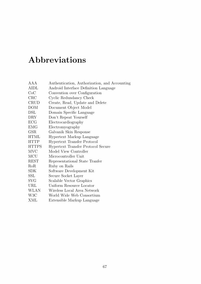
Abbreviations
AAA Authentication, Authorization, and AccountingAIDL Android Interface Definition LanguageCoC Convention over ConfigurationCRC Cyclic Redundancy CheckCRUD Create, Read, Update and DeleteDOM Document Object ModelDSL Domain Specific LanguageDRY Don’t Repeat YourselfECG ElectrocardiographyEMG ElectromyographyGSR Galvanik Skin ResponseHTML Hypertext Markup LanguageHTTP Hypertext Transfer ProtocolHTTPS Hypertext Transfer Protocol SecureMVC Model View ControllerMCU Microcontroller UnitREST Representational State TranferRoR Ruby on RailsSDK Software Development KitSSL Secure Socket LayerSVG Scalable Vector GraphicsURL Uniform Resource LocatorWLAN Wireless Local Area NetworkW3C World Wide Web ConsortiumXML Extensible Markup Language
67

68 ABBREVIATONS
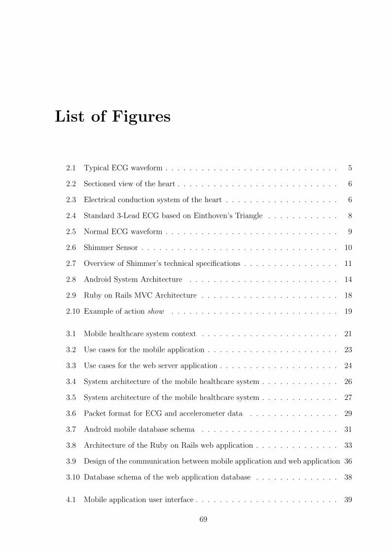
List of Figures
2.1 Typical ECG waveform . . . . . . . . . . . . . . . . . . . . . . . . . . . . . 5
2.2 Sectioned view of the heart . . . . . . . . . . . . . . . . . . . . . . . . . . . 6
2.3 Electrical conduction system of the heart . . . . . . . . . . . . . . . . . . . 6
2.4 Standard 3-Lead ECG based on Einthoven’s Triangle . . . . . . . . . . . . 8
2.5 Normal ECG waveform . . . . . . . . . . . . . . . . . . . . . . . . . . . . . 9
2.6 Shimmer Sensor . . . . . . . . . . . . . . . . . . . . . . . . . . . . . . . . . 10
2.7 Overview of Shimmer’s technical specifications . . . . . . . . . . . . . . . . 11
2.8 Android System Architecture . . . . . . . . . . . . . . . . . . . . . . . . . 14
2.9 Ruby on Rails MVC Architecture . . . . . . . . . . . . . . . . . . . . . . . 18
2.10 Example of action show . . . . . . . . . . . . . . . . . . . . . . . . . . . . 19
3.1 Mobile healthcare system context . . . . . . . . . . . . . . . . . . . . . . . 21
3.2 Use cases for the mobile application . . . . . . . . . . . . . . . . . . . . . . 23
3.3 Use cases for the web server application . . . . . . . . . . . . . . . . . . . . 24
3.4 System architecture of the mobile healthcare system . . . . . . . . . . . . . 26
3.5 System architecture of the mobile healthcare system . . . . . . . . . . . . . 27
3.6 Packet format for ECG and accelerometer data . . . . . . . . . . . . . . . 29
3.7 Android mobile database schema . . . . . . . . . . . . . . . . . . . . . . . 31
3.8 Architecture of the Ruby on Rails web application . . . . . . . . . . . . . . 33
3.9 Design of the communication between mobile application and web application 36
3.10 Database schema of the web application database . . . . . . . . . . . . . . 38
4.1 Mobile application user interface . . . . . . . . . . . . . . . . . . . . . . . . 39
69
70 LIST OF FIGURES
4.2 Composition of an activity . . . . . . . . . . . . . . . . . . . . . . . . . . . 40
4.3 The activity MainView and its decomposition in view components . . . . . 41
4.4 Implementation of an section in main.xml . . . . . . . . . . . . . . . . . . 41
4.5 Sequence diagram of the authentication process . . . . . . . . . . . . . . . 42
4.6 Class: ParseLoginHandler.java . . . . . . . . . . . . . . . . . . . . . . . . . 43
4.7 Example of an XML file received from the server . . . . . . . . . . . . . . . 44
4.8 User Interface of the BluetoothView activity . . . . . . . . . . . . . . . . . 45
4.9 Overview of the dynamic behavior of BluetoothView . . . . . . . . . . . . . 46
4.10 Package: bluetooth service . . . . . . . . . . . . . . . . . . . . . . . . . . . 46
4.11 Periodical recording intervals . . . . . . . . . . . . . . . . . . . . . . . . . . 47
4.12 Process initiated by receiving ECG data . . . . . . . . . . . . . . . . . . . 48
4.13 Package: record . . . . . . . . . . . . . . . . . . . . . . . . . . . . . . . . . 49
4.14 Package: parser . . . . . . . . . . . . . . . . . . . . . . . . . . . . . . . . . 50
4.15 Class diagram of the record handler process component . . . . . . . . . . . 50
4.16 Package: database . . . . . . . . . . . . . . . . . . . . . . . . . . . . . . . . 51
4.17 Package: network service . . . . . . . . . . . . . . . . . . . . . . . . . . . . 52
4.18 Records controller . . . . . . . . . . . . . . . . . . . . . . . . . . . . . . . . 53
4.19 ECG signal of lead 1, lead 2 and lead 3 displayed by the web application . 54
4.20 RoR components responsible for the visualization of an ECG trace . . . . . 55
List of Tables
2.1 Heart chambers viewed by the 3-lead ECG . . . . . . . . . . . . . . . . . . 8
2.2 Segments and intervals of an ECG wave . . . . . . . . . . . . . . . . . . . 9
2.3 Overview of Shimmer extension daughterboards . . . . . . . . . . . . . . . 11
2.4 Standard routing in Ruby on Rails . . . . . . . . . . . . . . . . . . . . . . 19
3.1 Overall system requirements . . . . . . . . . . . . . . . . . . . . . . . . . . 22
3.2 Requirements for the sensor component . . . . . . . . . . . . . . . . . . . . 22
3.3 Requirements for the mobile component . . . . . . . . . . . . . . . . . . . 24
3.4 Requirements for the web server application . . . . . . . . . . . . . . . . . 25
3.5 Package structure of the mobile phone application . . . . . . . . . . . . . . 29
3.6 Overwiew of the controllers developed for the web application . . . . . . . 34
3.7 Overview of plugins used for the web application . . . . . . . . . . . . . . . 35
71

72 LIST OF TABLES
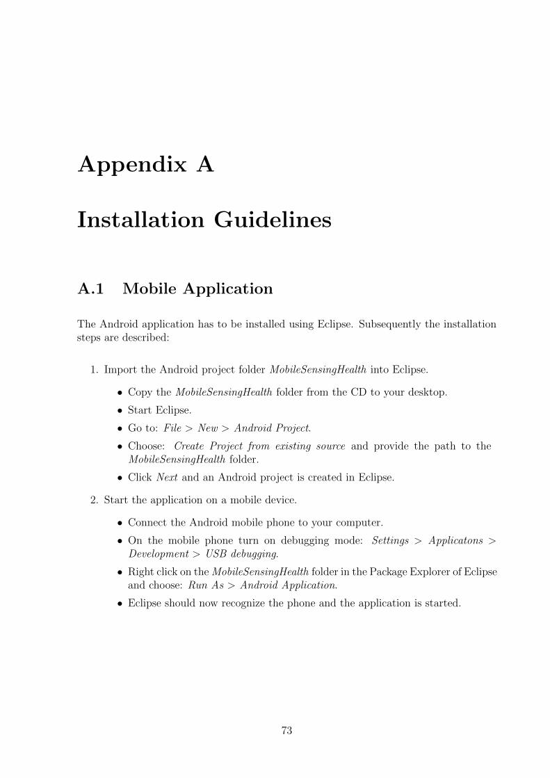
Appendix A
Installation Guidelines
A.1 Mobile Application
The Android application has to be installed using Eclipse. Subsequently the installationsteps are described:
1. Import the Android project folder MobileSensingHealth into Eclipse.
• Copy the MobileSensingHealth folder from the CD to your desktop.
• Start Eclipse.
• Go to: File > New > Android Project.
• Choose: Create Project from existing source and provide the path to theMobileSensingHealth folder.
• Click Next and an Android project is created in Eclipse.
2. Start the application on a mobile device.
• Connect the Android mobile phone to your computer.
• On the mobile phone turn on debugging mode: Settings > Applicatons >Development > USB debugging.
• Right click on the MobileSensingHealth folder in the Package Explorer of Eclipseand choose: Run As > Android Application.
• Eclipse should now recognize the phone and the application is started.
73
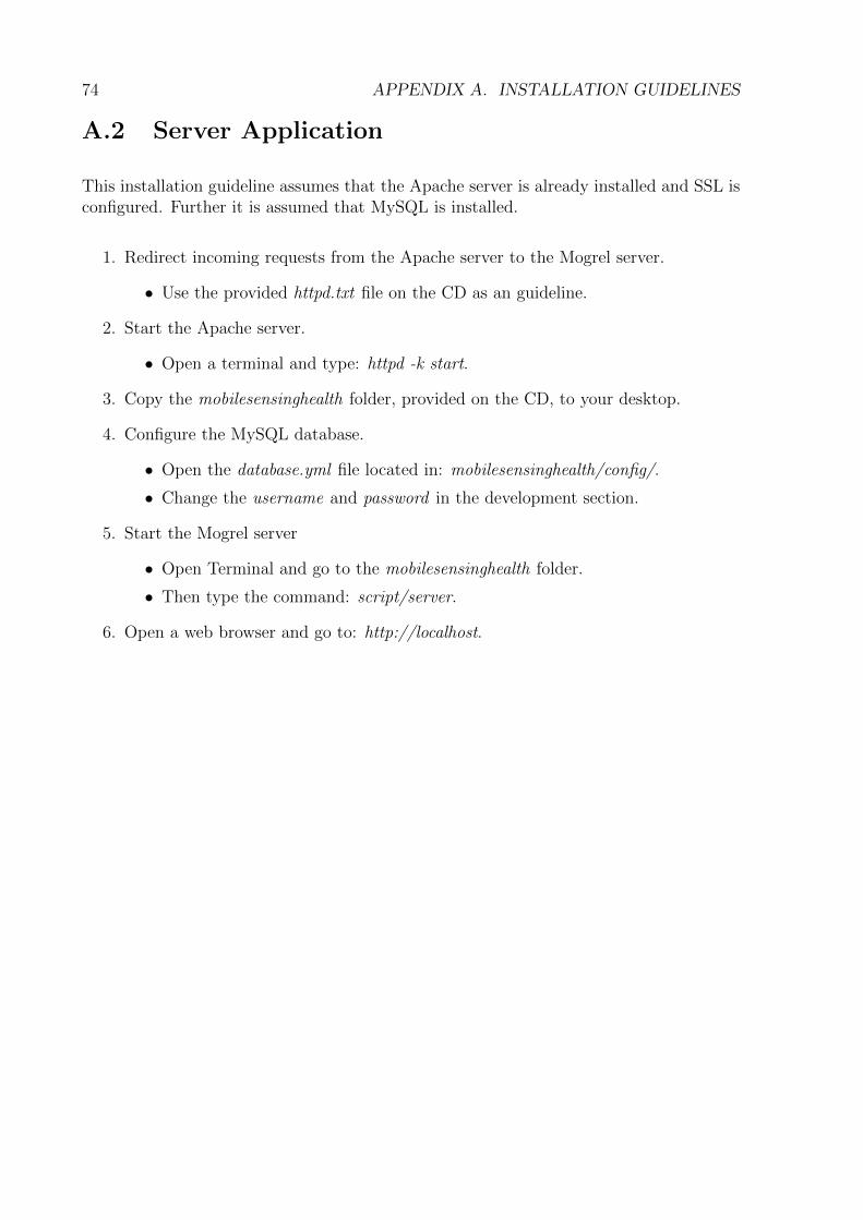
74 APPENDIX A. INSTALLATION GUIDELINES
A.2 Server Application
This installation guideline assumes that the Apache server is already installed and SSL isconfigured. Further it is assumed that MySQL is installed.
1. Redirect incoming requests from the Apache server to the Mogrel server.
• Use the provided httpd.txt file on the CD as an guideline.
2. Start the Apache server.
• Open a terminal and type: httpd -k start.
3. Copy the mobilesensinghealth folder, provided on the CD, to your desktop.
4. Configure the MySQL database.
• Open the database.yml file located in: mobilesensinghealth/config/.
• Change the username and password in the development section.
5. Start the Mogrel server
• Open Terminal and go to the mobilesensinghealth folder.
• Then type the command: script/server.
6. Open a web browser and go to: http://localhost.
Appendix B
Contents of the CD
The CD contains the following three folders:
• Thesis: contains the latex source code of the bachelor thesis and the abstractwritten in english and german.
– thesis.pdf
– thesis.ps
– abstract.pdf
– zfassung.pdf
• Mobile: contains the Android project folder.
– MobileSensingHealth
• Server: contains all files specific to the server development.
– httpd.txt: example of the configuration file used for the Apache server
– mobilesensinghealth: Folder containing the web application source code
75


