Embed Size (px)
Citation preview

1 a
ECE137B Final Exam
Wednesday 6/8/2016, 7:30-10:30PM.
There are7 problems on this exam and you have 3 hours
There are pages 1-32 in the exam: please make sure all are there.
Do not open this exam until told to do so.
Show all work.
Credit will not be given for correct answers if supporting work is not shown.
Class Crib sheets and 3 pages (front and back→ 6 surfaces) of your own notes permitted.
Don’t panic.
Time function LaPlace Transform
)(t 1
U(t) 1/s
)(tUe t
s
1 or
/1
/1
s
)(cos tUte d
t
22
ds
s
)(sin tUte d
t
22
d
d
s
Name: _________________________________
Problem points possible Problem points possible
1a 5 5a 10
1b 3 5b 2
1c 10 6a 10
1d 15 6b 10
2 10 6c 3
3 10 7 10
4 10 total 108

2 a
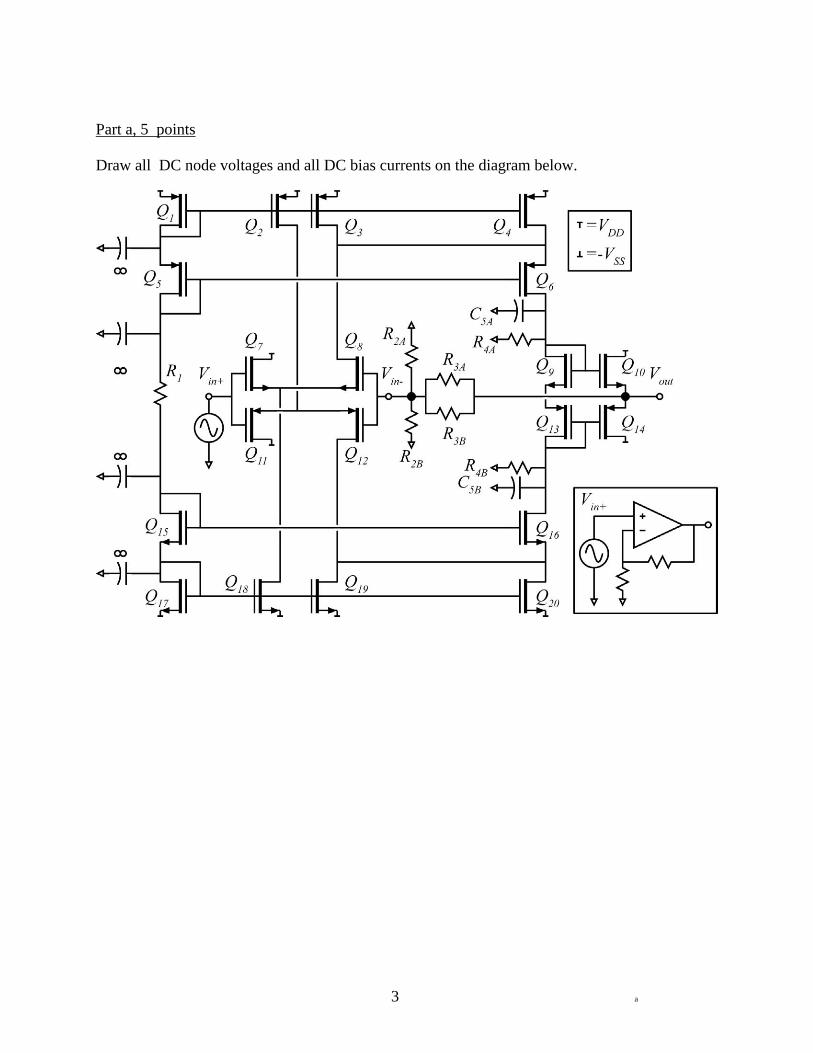
Problem 1, 33 points
method of first-order and second-order time constants. Some negative feedback
Above is a high-speed op-amp. It is connected, as the inset image suggests, as a positive voltage-
gain stage.
All FETs are short-channel devices with gL = 45nm
)( VVVWcvI thgsgoxsatd where oxsatcv =1mS/micrometer and 2.0)( VVth Volts.
All FETs have =0 V-1 , all have gW =1 micrometers,
except Q2 and Q18, which have =0 V-1 , and gW =2 micrometers,
Q10,11,12,14 have gsC = ggg WWL mfF/ 5.0mfF/ 33.6 2 and gdC = gWmfF/ 5.0 ,
Q7,8 have gsC = ggg WWL mfF/ 5.0mfF/ 33.6 2 and gdC =0 fF.
Q1,2,3,4,5,6,9,13,15,16,17,18,19,20 have gsC =0 fF and gdC =0 fF.
Note the indicated infinite bypass capacitors; these are AC grounds.
Pick 1R so that the current through it is 0.1 mA.
ba RR 44 2M, bA CC 55 400fF.
ba RR 22 2k, ba RR 33 8k
The supplies are +1.5V and -1.5V.
3 a
Part a, 5 points
Draw all DC node voltages and all DC bias currents on the diagram below.

4 a

5 a
Part b, 3 points
Symmetry allows us to analyze bandwidth and gain with the half-circuit below:
To compute the loop transmission you must (1) set Vgen to zero, (2) cut the feedback loop as
shown (3) restore the stage loading which has been removed by making the cut, (4) insert an AC
voltage generator at the cut point, and (5) compute the voltage gain once around the loop.

6 a
Indicate on the drawing above what circuit element must be placed in the box
labeled with a "?", and give the value of this element.

7 a
Part c, 10 points
Working with the circuit diagram of the previous page, determine the DC value of the loop
transmission.
TDC=____________

8 a

9 a
Part d, 15 points
Using MOTC, you will find the frequency, in Hz (not rad/sec), of the two major poles in the loop
transmission T. Hint: you can use the source degeneration model for Q7-Q8.
Find all the following.
1051 gdA CCC 82 gsCC : 103 gsCC
0
11R = 0
22R = 0
33R =
1
22R = 1
33R = 2
33R =
1pf = 2pf =

10 a

11 a
12 a
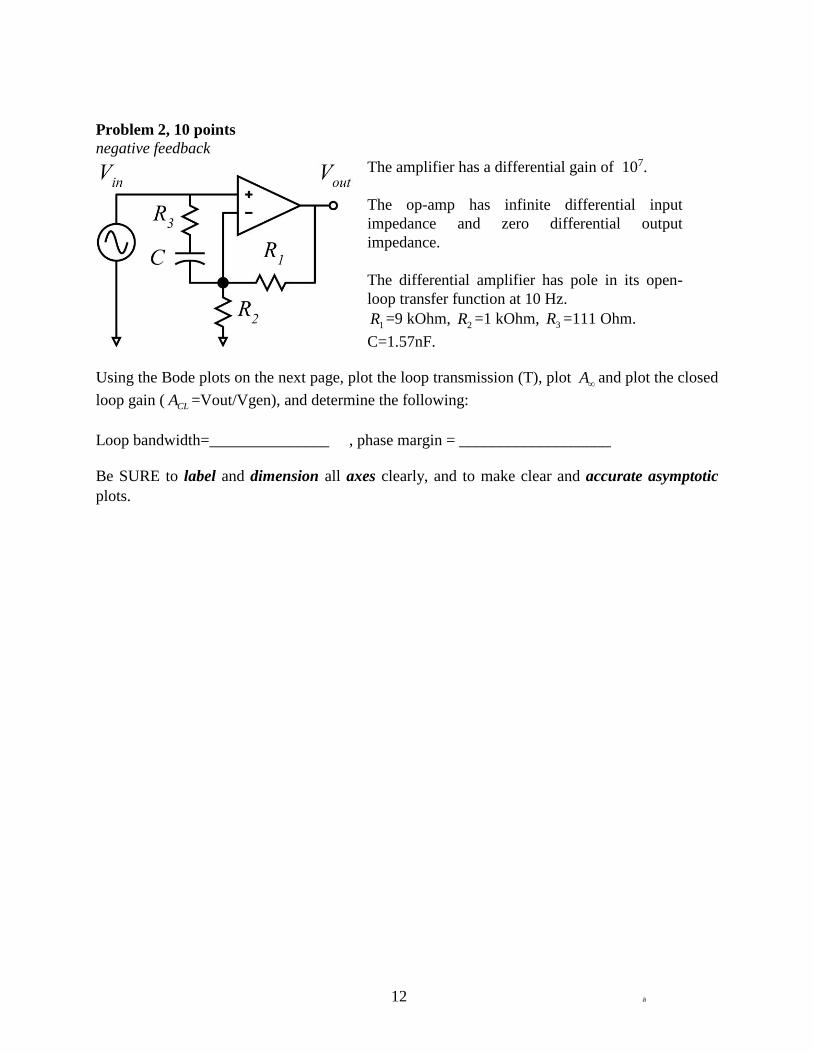
Problem 2, 10 points
negative feedback
The amplifier has a differential gain of 107.
The op-amp has infinite differential input
impedance and zero differential output
impedance.
The differential amplifier has pole in its open-
loop transfer function at 10 Hz.
1R =9 kOhm, 2R =1 kOhm, 3R =111 Ohm.
C=1.57nF.
Using the Bode plots on the next page, plot the loop transmission (T), plot A and plot the closed
loop gain ( CLA =Vout/Vgen), and determine the following:
Loop bandwidth=_______________ , phase margin = ___________________
Be SURE to label and dimension all axes clearly, and to make clear and accurate asymptotic
plots.

13 a
Plot T, A_(infinity), on this plot
1 10 100 1000 104
105
106
107
108
Frequency, Hz
draw closed loop gain on this bode plot
1 10 100 1000 104
105
106
107
108
Frequency, Hz

14 a

15 a
Problem 3, 10 points
negative feedback
The op-amps are ideal: infinite gain, infinite differential input impedance and zero output
impedance.
1R =100 Ohm, 2R =1 kOhm, C1=15.9pF, R3=333Ohms, R4=1kOhm, C2=159pF.
Using the Bode plots on the next page, plot the loop transmission (T) of the overall feedback
loop around the two op-amps, plot A and plot the closed loop gain ( CLA =Vout/Vgen), and
determine the following:
Loop bandwidth=_______________ , phase margin = ___________________
Be SURE to label and dimension all axes clearly, and to make clear and accurate asymptotic
plots.

16 a
Plot T, A_(infinity), on this plot
1 10 100 1000 104
105
106
107
108
Frequency, Hz
draw closed loop gain on this bode plot
1 10 100 1000 104
105
106
107
108
Frequency, Hz

17 a

18 a
Problem 4, 10 points
negative feedback
The amplifier has a differential gain of 107.
The op-amp has infinite differential input
impedance and zero differential output
impedance.
The differential amplifier has one pole in its
open-loop transfer function at 1 Hz.
1R =9 kOhm, 2R =1 kOhm, C=88.3pF
Using the Bode plots on the next page, plot the open-loop gain ( dA or olA ), the inverse of the
feedback factor ( /1 ) , closed loop gain ( CLA ), and determine the following:
Loop bandwidth=_______________ . Amplifier 3dB bandwidth=_______________
Be SURE to label and dimension all axes clearly, and to make clear and accurate asymptotic
plots.

19 a
Draw open loop gain (Ad) and 1/beta on this plot
1 10 100 1000 104
105
106
107
108
Frequency, Hz
draw closed loop gain on this bode plot
1 10 100 1000 104
105
106
107
108
Frequency, Hz

20 a

21 a
Problem 5: 12 points
method of time constants analysis
part a, 10 points
Using MOTC, find the transfer function Vout(s)/Vgen(s). Working with the transfer function in
standard form, i.e. ...1
...1
)(
)(2
21
2
21
sasa
sbsb
V
V
sV
sV
DCgen
out
gen
out give algebraic answers in the blanks
below
DCgen
out
V
V______________________
1a _____________________ 2a _____________________
1b _____________________
You need some method other than MOTC to get the zero time constant b1. Nodal analysis,
solving only for the numerator, would do this, but is hard work. Hint: What would
happen to Vout if the impedance of the parallel R2||C2 network were infinite ? Does that
tell you the zero frequency ?

22 a

23 a

24 a
part b, 2 points
Now, R1=1 k, R2=2 k, R3=3 k, C1=1 F, C2=2 F. Again find a1 and a2 and Vout/Vgen
at DC.
DCgen
out
V
V______________________
1a _____________________ 2a _____________________

25 a
Problem 6: 23 points
Nodal analysis and transistor circuit models
Ignore DC bias; you don't need
it.
FET: gsC =0fF, gdC =0 fF,
dsR =infinity.
** mg is nonzero**
Part a, 10 points
Draw an accurate small-signal equivalent circuit model of the circuit above. Do not show
components whose element values are zero or infinity (!).
Important hint:
(1) use a hybrid-pi model, not a T-model, for the FET

26 a
Part b, 10 points
Using NODAL ANALYSIS, find the input admittance Yin(s)=Iin(s)/Vin(s)
The answer must be in the form ...1
...1)()(
2
21
2
21
sasa
sbsbsYsY n
xin ,
where xY has units of (Amps/Volt), n might be any positive or negative integer (or n might be
zero), and has units of time
xY =__________________ , =__________________ , n =__________________ ,
1a _________________ , 2a _________________ 1b _________________ ,
2b _________________

27 a

28 a

29 a
Part c, 3 points
Now set: mg = 1mS, 1C =1 pF,
2C =2 pF. Find the numeric value (real and imaginary part) for
Yin at 10 MHz. Do not be surprised if the answer appears to be an unexpected value.
)10( MHzYin =_______________

30 a

31 a
Problem 7, 10 points
mental Fourier Transforms
An amplifier has 3dB gain, is non-inverting, has a low-frequency cutoff, at the -3dB point, of
100kHz, and a high-frequency cutoff, at the -3dB point, of 1 MHz. Below the low-frequency
3dB point, the gain varies as 20dB/decade. Above the high-frequency 3dB point, the gain varies
as -20dB/decade.
Plot below an accurate Bode plot of Vout/Vgen and an accurate plot of its step response with a 1
V step-function input. Label and dimension axes.
dB
Frequency
Bode Magnitude plot-please label axes

32 a
-0.5
0
0.5
1
1.5
2
output voltage with Vin(t) = 1 Volt step functionV
ou
t(t)
time