Embed Size (px)
Citation preview
1
Instructor:
Kai Sun
Fall 2015
ECE 325 – Electric Energy System Components2- Fundamentals of Electrical Circuits
2
Content
•Fundamentals of electrical circuits (Ch. 2.0-2.15, 2.32-2.39)
•Active power, reactive power and apparent power
(Ch. 7)
•Three-phase AC systems (Ch. 8)

3
Notations: Current and Alternating Current
• Arbitrarily determine a positive direction, e.g. 12
– If a current of 2A flows from 1 to 2, I=+2A
– If a current of 2A flows from 2 to 1, I= -2A
G
2
1
I
I >0 I <0

4
Notations: Voltage
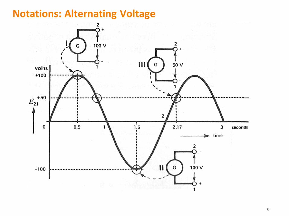
1. Double-subscript notation:
E21= +100V (the voltage between 2 and 1
is 100V, and 2 is positive w.r.t 1)
E12 = -100V
2. Sign notation:
Arbitrarily mark a terminal with (+), E=E21=+100V if that terminal is the actual
terminal (+); Otherwise, E=E12=-100V
100V
+
-
2
1
G
100V
2
1
+
E
Both the double-subscript notation and
sign notation apply to alternating voltage
5
Notations: Alternating Voltage

6
Notations: Sources and Loads
• Definition: given the instantaneous, actual polarity of voltage and direction of current
– Source: whenever current flows out of the terminal (+)
– Load: whenever current flows into the terminal (+)
• How about these?
– Resistor, battery cell, electric motor, capacitor and inductor

7
i(t)+
v(t)
Resistor
Inductor Capacitor

8
1-Phase AC System with Sinusoidal Voltage and Current
• e , i: instantaneous voltage (V) and current (A)
• Em , Im : peak values of the sinusoidal voltage (V) and current (A)
• = 2f (rad/s): angular frequency
• e , i : constant phase angles (rad or deg) of voltage and current
• Em/ 2, Im/ 2: RMS (root-mean-square, effective) values
( ) cos( )m ee t E t
( ) cos( )m ii t I t
Load
+
22 2[ ( )]
2 2
tm m
dc dct T
I RT II RT i t Rdt I
Equal heating effects

9
Phasor Representation
• E and I are called RMS phasors of e(t) and i(t);
E leads I by = e- i or in other words, I leads E by 2-
• Phasor:
– a complex number that carries the amplitude and phase angle
information of a sinusoidal signal of a common frequency () w.r.t. a chosen reference signal.
– a mapping from the time domain to complex number domain.
( ) cos( )
( ) cos( )
m e
m i
e t t
i
E
It t
2
2
me
mi
EE
II
2 cos( )| |
|2 c s( )| o
e
i
E
I
t
t
| | | |
| | | |
e
i
j
e
i
j
E E e
I I e

10
Impedance
• Impedance is a complex number () defined as
• Purely resistive:
• Purely inductive:
• Purely capacitive:
| | eE E
| | iI I +
def12
| || | ( )
| |
ee i
i
EE EZ Z R jX
I I I
| |Z Z R
| | 90 LZ Z jX j L
1
2
12E
1| | 90 CZ Z jX j
C
Z
Impedance of branch 1-2 =
(Voltage drop on 1-2)
(Current flow into 1)def
e i (Impedance angle)

11
Example 2-5
• Draw the phasor diagram of the voltage and current at a frequency
of 60Hz. Calculate the time
interval t between the positive peaks of E and I
Solution:
=2f=377 (rad/s)=21600 (deg/s)
|E|=339/2=240 (V)
|I|=14.1/2=10 (A)
Choose an arbitrary reference to
draw phasors E and I
t=30/21600=0.00139 (s)
E240V
I10A
30o
( ) 339cos(21600 90 )
( ) 14.1cos(21600 120 )
e t t
i t t
,t

12
Kirchhoff’s Voltage Law (KVL)
• The algebraic sum of the voltages around a closed loop (CW/CCW) is zero
( voltage rises = voltage drops)
– Applied to both instantaneous voltages or voltage phasors
• Loop 24312 (BCDA, CW):
E24+E43+E31+E12=0 or
e24+e43+e31+e12=0
• Loop 2342 (ECF, CCW):
E23+E34+E42=0 or
e23+e34+e42=0
E12
E43
E31
E24
E23
42
1
3
E34
E42

13
Kirchhoff’s Current Law (KCL)
• The algebraic sum of the currents arriving at a node is equal to 0.
( currents in = currents out)
• Node A:
I1+I3+(-I2)+(-I4)+(-I5)=0
or i1+i3+(-i2)+(-i4)+(-i5)=0
I1+I3=I2+I4+I5
or i1+i3=i2+i4+i5
A

14
• KVL
– Loop 24312, CW:
E24 +E43 +E31 +E12 =0
I2Z2 -I3Z3 +Eb -I1Z1 =0
– Loop 2342, CCW:
E23 +E34 +E42 =0
I4Z4 +I3Z3 -I2Z2 =0
– Loop 242, CW:
E24 + E42 =0
Ea - I2Z2 =0
+
+
Kirchhoff’s Laws and AC Circuits
• KCL
– Node 2:
I5 -I2 -I4 -I1=0
– Node 3:
I4 +I1 – I3=0
Ea
Eb

15
Examples 2-14 ~ 2-16

16
Impedance angle:
>0 for inductive load and
<0 for capacitive load
( ) ( ) ( ) cos( )cos( )
1 cos( ) cos(2 )
2
1 cos( ) cos[2( ) ( )]
2
1 cos cos[2( ) ]
2
1 cos cos cos 2( ) sin sin 2( )
2
m m e i
m m e i e i
m m e i e e i
m m e
m m e e
p t e t i t E I
E I
E I
E I
E I
| | / 2
| | / 2
m
m
E E
I I
e i
( ) cos [1 cos 2( )] sin sin 2( )
R X
e e
p p
p E I E I
Using trigonometric identity
1cos cos cos( - ) cos( )
2A B A B A B
Instantaneous Power
( ) cos( )m ee t E t
( ) cos( )m ii t I t
Load
Z
+
t

17
100cose 1.25 60 0.625 1.0825 ΩZ j
8060
2I
80cos( 60 )oi
Example:100
0 2
E
( ) cos [1 cos 2( )] sin sin 2( )
2000(1 cos 2 ) 3464sin 2
R X
XR
e e
p p
pp
p E I E I
2000
3464
ei

18
Observations:
• The frequency of p, pR and pX is twice of e and i, which is 602=120Hz
• pR(t)
– changes between 0 and 4000 (=2|E||I|cos )
– always 0, and has an average value of 2000 (=|E||I|cos )
– is the power consumed by the load
• pX(t)
– changes between 3464 (= |E||I|sin)
– has an average value of 0
– is the power borrowed & returned by the load.
( ) ( )
( )( )
( ) cos [1 cos 2( )] sin sin 2( )
(1 cos 2 320 46 n 200 ) 4si
R X
XR
e e
p t p t
p tp t
p t E I E I

19
Apparent, Active (Real) and Reactive Powers
• Real or active power (average power)
• Unit ~ watt or W
• Power factor (PF): cos= cos(e-i)
– The PF is said to be lagging if =e-i >0 or leading if <0
def
| | | | cosP E I
def
| | | | sinQ E I
( ) ( )
[1 cos 2( )] sin 2( )
[1 cos 2( )]
cos
sin 2( )
sin
R X
e e
p t p t
e e
E I
QP
p E I
• Reactive power
• Unit ~ var (volt-ampere reactive). Some people use Var, VAR or VAr
• Q>0 if =e-i >0 (inductive) or Q<0 if <0 (capacitive)
P
Q
def
| | | | | |S E I
• Apparent power
• Unit ~ volt ampere or VA (kVA or MVA)

20
Complex Power and Power Triangle
• =tan-1(Q/P)
– If >0 (i <e, i.e. lagging PF), then Q>0, which means a reactive load (inductive)
– If <0 (i >e, i.e. leading PF), then Q<0, which
means a reactive source (capacitive)
def
= PS jQ cos i s nE I j E I
2 2| | I P QE S
R
XZ
S
• PF=cos=P/|S| (+/- sign of Q tells a lagging/leading PF)
P=|S| cos=|S| PF
• If the load impedance is Z=E/I, then
S = ZII*= Z|I|2= R|I|2+jX|I|2 = P + jQ
P=R|I|2 Q=X|I|2
is also called the load impedance angle
Power triangle
Q
p qE I Ij E Ip
Iq
*
e i e i EE I I IE

21
Other Useful Formulas
• If Z is purely resistive
• If Z is purely reactive
2**
* *
* 2 | |
EEES EI
Z Z
II Z I Z
2
* 2| |
E SZ
S I
2E
PR
2 2 2
or 1/
E E EQ
X L C

22
Examples 7-2 & 7-3

23
Saadat’s Example 2.2
1
2 3
1200 0 V, 60 0 ,
6 12 , 30 30
V Z j
Z j Z j
Find the power absorbed by each load
and the total complex power
1
1
2
2
3
3
1200 0 120020 0 A
60 0 60
1200 0 200 200(1 2)40 80 A
6 12 1 2 5
1200 0 40 40(1 )20 20 A
30 30 1 2
VI j
Z j
V jI j
Z j j
V jI j
Z j j
1 2 3 96,000 W+ 72,000 varS S S S j
*
1 1
*
2 2
*
3 3
1200 0 (20 0) 24,000 W+ 0 var
1200 0 (40 80) 48,000 W+ 96,000 var
1200 0 (20 20) 24,000 W 24,000 var
S VI j j
S VI j j
S VI j j
S1
S2
S3
S
24
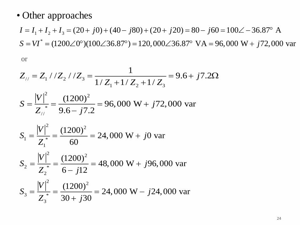
• Other approaches
1 2 3
*
(20 0) (40 80) (20 20) 80 60 100 36.87 A
(1200 0 )(100 36.87 ) 120,000 36.87 VA 96,000 W 72,000 var
I I I I j j j j
S VI j
2 2
1 *
1
2 2
2 *
2
2 2
3 *
3
(1200)24,000 W 0 var
60
(1200)48,000 W 96,000 var
6 12
(1200)24,000 W 24,000 var
30 30
VS j
Z
VS j
Z j
VS j
Z j
/ / 1 2 3
1 2 3
2 2
*
/ /
1/ / / / 9.6 7.2
1/ 1/ 1/
(1200)96,000 W 72,000 var
9.6 7.2
Z Z Z Z jZ Z Z
VS j
Z j
or

25
Three-Phase Systems
• Balanced 3-phase voltage:
• Sequence: a-b-c (CW).
• Phase voltages are displaced at
120o (a leads b, b leads c, and c leads a by 120o, respectively)
• Equal voltage magnitudes

26
3-Phase, 4-Wire AC System
Ia+Ib+Ic
=Ea1/R+Eb2/R+Ec3/R
=(Ea1+Eb2+Ec3)/R
=0

27
3-Phase, 3-Wire AC System
• Line currents:
|Ia|=|Ib|=|Ic|= IL
• Phase voltages (phase-to-neutral or
line-to-neutral):
|Ean|=|Ebn|=|Ecn|= ELN
• From KVL, line voltages (line-to-line or phase-to-phase):
Eab=Ean+Enb=Ean-Ebn
Ebc=Ebn+Enc=Ebn-Ecn
Eca=Ecn+Ena=Ecn-Ean
|Eab|=|Ebc|=|Eca|= EL
• EL=3 ELN 1.73 ELN

28
Wye (Y) Connection
• Each line current (Ia, Ib and Ic) equals
the phase current.
IL = IZ
• Each line voltage is 3=1.73 times of
a phase voltage in magnitude
EL=3 ELN ( |Eab|= 3 |Ean| )
• Apparent power of each phase:
• Total 3-phase apparent, active and reactive power:
| |3
LZ LN Z L
ES E I I
22
3 3 3 | || |3
| | 3 L LL L
L L Y
Y
S EE E
II I ZZ
3 3 cosL LP E I
3 3 sinL LQ E I
| |Y YZ Z
a
b
c
a
b
c
ab
bc
ca
is the power factor angle
and load impedance angle

29
Delta () Connection
• From KCL:
Ia=Iab-Ica
Ib=Ibc-Iab
Ic=Ica-Ibc
Because three equations are symmetric, and Ia leads Ib, Ib leads Ic and Ic leads Ia all by
120o, we may easily conclude:
1. |Iab|=|Ibc|=|Ica|=IZ
2. Iab leads Ibc, Ibc leads Ica, and
Ica leads Iab by 120o, respectively
• Each line current is 3=1.73 times of a phase current in magnitude
IL=3 IZ ( |Ia|= 3 |Iab| )
• Each phase voltage equals the line voltage
ELN = EL
a
b
c
Iab
Ibc
Ica

30
Delta () Connection
• Apparent power of each phase:
• Total 3-phase apparent, active and reactive power:
• Given line voltage EL, line current IL and power factor cos, calculation of power is independent of the connection (Y / )
22
3
33 | |
| || 3
3| L L
L LL L
IS E II
EE Z
Z
|ZY|=|Z|/3
| |Z Z
a
b
c
Iab
Ibc
Ica
| |3
LZ L Z L
IS E I E
3 3 cosL LP E I
3 3 sinL LQ E I
is the power factor angle
and load impedance angle

31
Examples 8-8 & 8-11

32
Homework #1
• Read Ch. 2.0-2.15, 2.32-2.39, Ch. 7
• Answer Questions 2-1, 2-2, 2-10, 2-15, 2-26,
7-11, 7-12, 7-13, 7-14, 7-17, 7-20, 7-22
• Due date:
– hand in your solution in the class on 9/9 or
– to Denis at MK 205 or by email ([email protected])
before the end of 9/11