Embed Size (px)
Citation preview
Simon Fraser University
2
Dept. of Chemistry (Physics#)
Simon Fraser University
Burnaby, British Columbia
Canada
Model Polymers for Fuel Cell Membranes.
E.M.W. Tsang, A. Yang, Z. Shi,T. Weissbach, R. Narimana,# B. Frisken,#
S. Holdcroft*
Funding:Dec, 2013,ICAER 2013
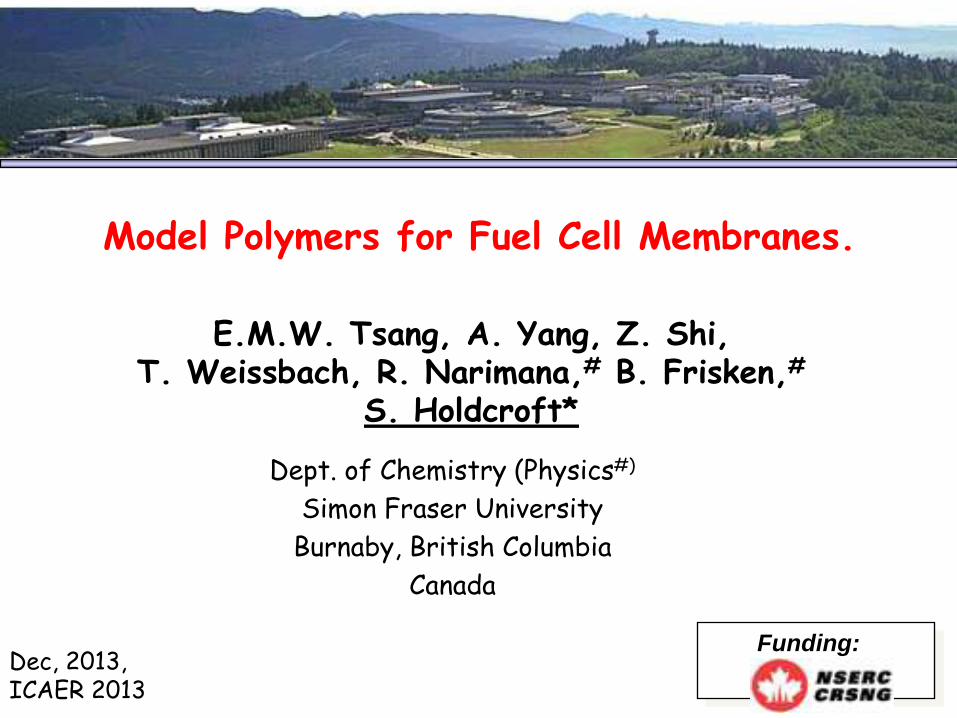
Proton Exchange Membrane Fuel Cell (PEMFC)
Cathode Reaction
O2
+ 4e
O2
H2O
+ 4H + - 2H 2O
H2
Anode Reaction
2H2
4H ++ 4e -
Proton Exchange
Membrane (PEM)
ElectrodeCatalyst
H+
e-
e-
(Hydrogen)
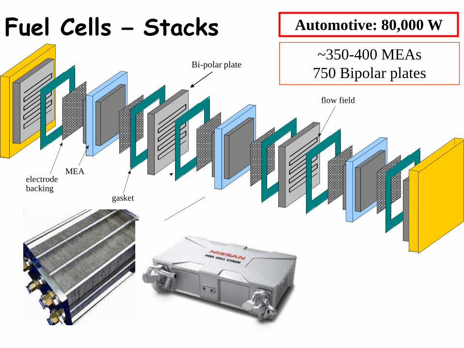
Fuel Cells – Stacks
gasket
electrodebacking
MEA
flow field
Bi-polar plate
Automotive: 80,000 W
~350-400 MEAs
750 Bipolar plates
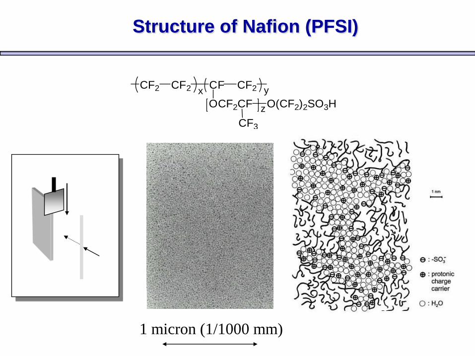
Structure of Nafion (PFSI)
CF2 CF2 CF CF2
OCF2CF
CF3
O(CF2)2SO3H
x y
z
1 micron (1/1000 mm)
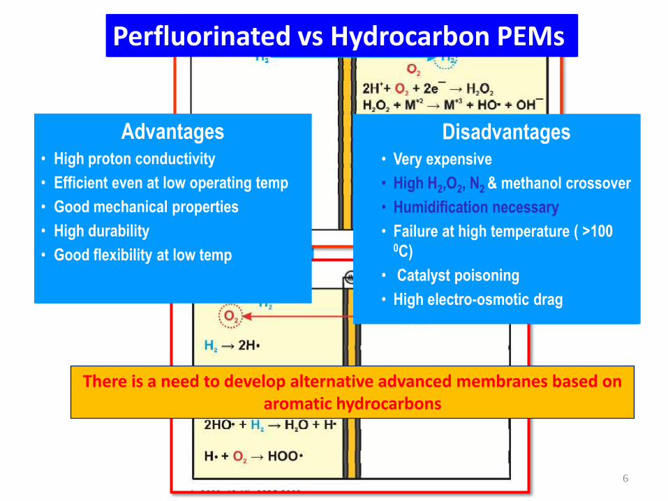
Disadvantages• Very expensive
• High H2,O2, N2 & methanol crossover
• Humidification necessary
• Failure at high temperature ( >100 0C)
• Catalyst poisoning
• High electro-osmotic drag
Advantages• High proton conductivity
• Efficient even at low operating temp
• Good mechanical properties
• High durability
• Good flexibility at low temp
Perfluorinated vs Hydrocarbon PEMs
6
There is a need to develop alternative advanced membranes based on aromatic hydrocarbons
Disadvantages• Very expensive
• High H2,O2, N2 & methanol crossover
• Humidification necessary
• Failure at high temperature ( >100 0C)
• Catalyst poisoning
• High electro-osmotic drag
Advantages• High proton conductivity
• Efficient even at low operating temp
• Good mechanical properties
• High durability
• Good flexibility at low temp
Perfluorinated vs Hydrocarbon PEMs
7
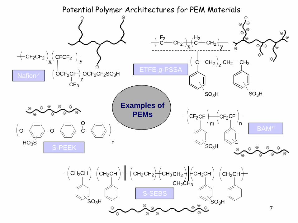
F2C CF2
H2C CH2
C CH2 CH2 CH2
SO3H
x y
z
SO3H
CF2CF
SO3H
CF2CF
m n
R
ETFE-g-PSSA
BAM
S-SEBS
CH2CH
SO3H
CH2CH CH2CH2 CH3CH2
CH2CH3
CH2CH
SO3H
CH2CH
Nafion
CF2CF2x
CFCF2y
OCF2CF
CF3
OCF2CF2SO3Hz
Examples of
PEMs
O O C
O
nHO3SS-PEEK
Potential Polymer Architectures for PEM Materials
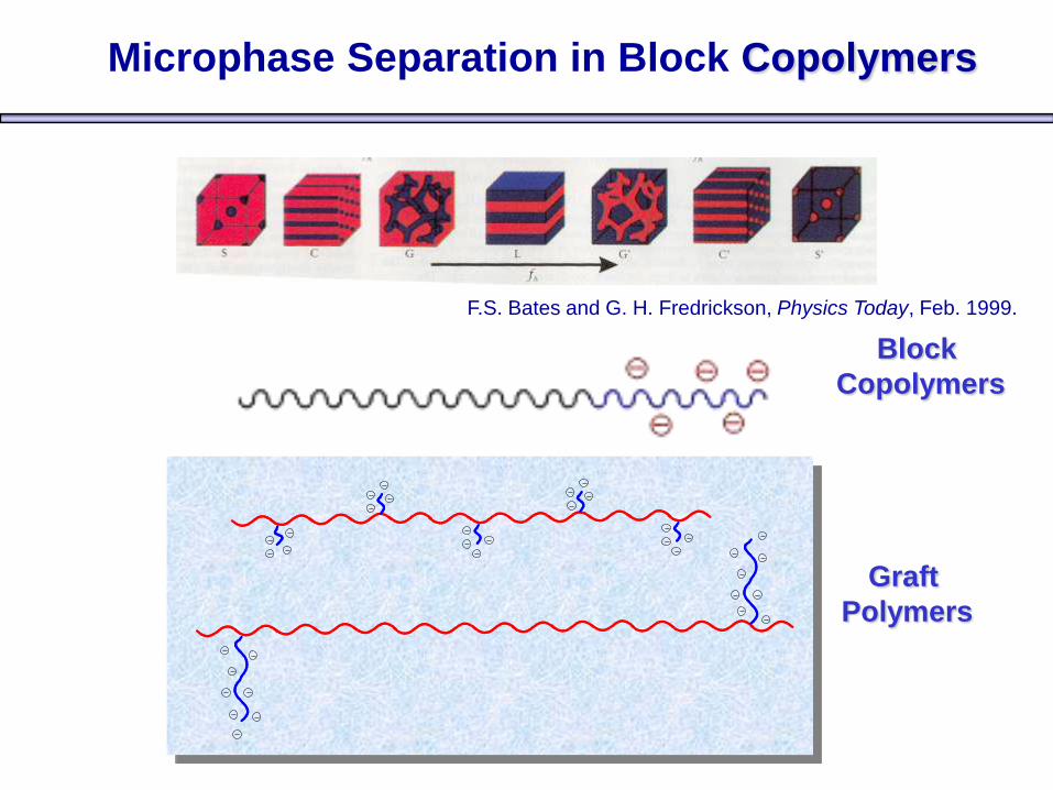
Microphase Separation in Block Copolymers
F.S. Bates and G. H. Fredrickson, Physics Today, Feb. 1999.
Block
Copolymers
Graft
Polymers
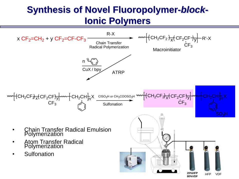
Chain Transfer Radical Polymerization Macroinitiator
x CF2=CH2 + y CF2=CF-CF3
CuX / bpy
Sulfonation
R-XCH2CF2 CF2CFx y R'-X
CF3
ATRP
CH2CF2 CF2CF CH2CH
CF3
n
x y nClSO3H or CH3COOSO3H CH2CF2 CF2CF CH2CH
SO3H
CF3
x y nX X
• Chain Transfer Radical Emulsion Polymerization
• Atom Transfer Radical Polymerization
• Sulfonation
Synthesis of Novel Fluoropolymer-block-
Ionic Polymers
HFP VDF20%HFP80%VDF
10
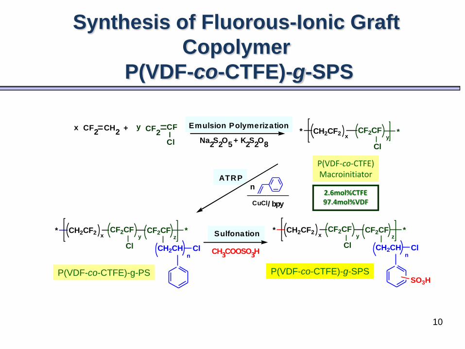
Synthesis of Fluorous-Ionic Graft
Copolymer
P(VDF-co-CTFE)-g-SPS
P(VDF-co-CTFE)-g-SPS
P(VDF-co-CTFE)Macroinitiator
P(VDF-co-CTFE)-g-PS
CF2
CH2 CF
2CFx y+
Cl
Emulsion Polymerization
n
CuCl/ bpy
ATRP
CH3COOSO3H
Sulfonation
Na2S
2O
5+ K
2S
2O
8
* CH2CF2 CF2CFyx
*
Cl
* CH2CF2 CF2CFyx
Cl
CF2CFz
*
CH2CHn
Cl
* CH2CF2 CF2CFyx
Cl
CF2CFz
*
CH2CHn
Cl
SO3H
2.6mol%CTFE 97.4mol%VDF
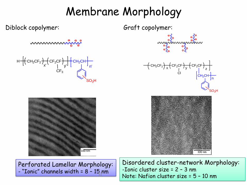
Membrane Morphology
Perforated Lamellar Morphology:- “Ionic” channels width = 8 – 15 nm
CF2CFCH2CF2
CF3
CH2CH
SO3H
x' y' n'
H
100 nm
CH2CF2 CF2CFx y
CF2CF
CH2CH
z
n
SO3H
Cl
Disordered cluster-network Morphology:-Ionic cluster size = 2 – 3 nmNote: Nafion cluster size = 5 – 10 nm
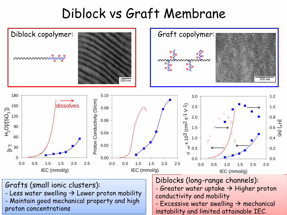
Graft copolymer:Diblock copolymer:
11
100 nm
IEC (mmol/g)
0.0 0.5 1.0 1.5 2.0 2.5
H2O
]/[S
O3
- ])
0
30
60
90
120
150
180
IEC (mmol/g)
0.0 0.5 1.0 1.5 2.0 2.5
Pro
ton C
onductivity (
S/c
m)
0.00
0.02
0.04
0.06
0.08
0.10
Diblock vs Graft Membrane
Diblocks (long-range channels):- Greater water uptake Higher proton conductivity and mobility- Excessive water swelling mechanical instability and limited attainable IEC.
Grafts (small ionic clusters):- Less water swelling Lower proton mobility- Maintain good mechanical property and high proton concentrations
IEC (mmol/g)
0.0 0.5 1.0 1.5 2.0 2.5
eff x
103
(cm
2 s
-1 V
-1)
0.0
0.5
1.0
1.5
2.0
2.5
3.0
[H+
] (M)
0.0
0.2
0.4
0.6
0.8
1.0
1.2
Graft copolymer:
100 nm
Diblock copolymer:
100 nm
dissolves
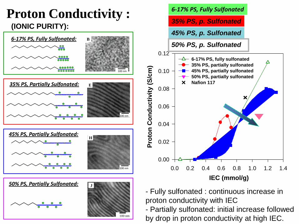
6-17% PS, Fully Sulfonated:
45% PS, Partially Sulfonated:
35% PS, Partially Sulfonated:
100 nm
E
B
100 nm
100 nm
H
100 nm
J50% PS, Partially Sulfonated:
Proton Conductivity :
IEC (mmol/g)
0.0 0.2 0.4 0.6 0.8 1.0 1.2 1.4
Pro
ton
Co
nd
ucti
vit
y (
S/c
m)
0.00
0.02
0.04
0.06
0.08
0.10
0.126-17% PS, fully sulfonated
35% PS, partially sulfonated
45% PS, partially sulfonated
50% PS, partially sulfonated
Nafion 117
13
- Fully sulfonated : continuous increase in
proton conductivity with IEC
- Partially sulfonated: initial increase followed
by drop in proton conductivity at high IEC.
6-17% PS, Fully Sulfonated
35% PS, p. Sulfonated
45% PS, p. Sulfonated
50% PS, p. Sulfonated
(IONIC PURITY):
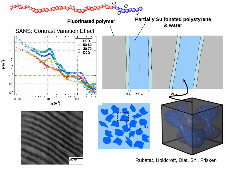
Fluorinated polymer Partially Sulfonated polystyrene
& water
SANS: Contrast Variation Effect
Rubatat, Holdcroft, Diat, Shi. Frisken100 nm
Conclusions
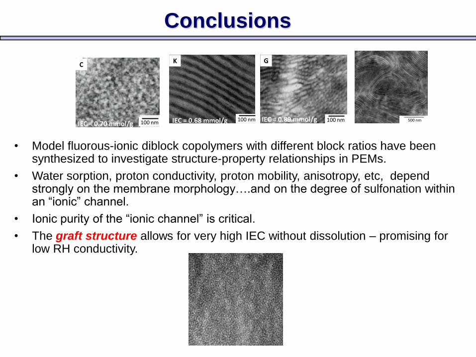
• Model fluorous-ionic diblock copolymers with different block ratios have been synthesized to investigate structure-property relationships in PEMs.
• Water sorption, proton conductivity, proton mobility, anisotropy, etc, depend strongly on the membrane morphology….and on the degree of sulfonation within an “ionic” channel.
• Ionic purity of the “ionic channel” is critical.
• The graft structure allows for very high IEC without dissolution – promising for low RH conductivity.
100 nm
G
IEC = 0.89 mmol/g100 nm
K
IEC = 0.68 mmol/g100 nm
C
IEC = 0.70 mmol/g500 nm500 nm500 nm
T.J. Peckham, S. Holdcroft. Adv. Mater., 22 (2010) 4667–4690
Yossef Elabd and Michael Hickner“Block Copolymers for Fuel Cells”
Macromolecules, 2011, 44 (1), pp 1–11