Embed Size (px)
Citation preview
EC312 Lesson 15: Antennas
Objectives:(a) Describe the role of the antenna in a wireless communication system.
(b) Use the five parameters associated with the design of three antennas to solve design problems.
(c) Determine an antenna's gain relative to an isotropic point source (dBi).
(d) Explain the relationship between an antenna's beamwidth and gain.
(e) Compare and contrast the advantages and disadvantages of directional antennas, specifically a Yagi antenna.
(f) Describe the role of directors and reflectors in the design of a directional antenna.
(g) Interpret an antenna's radiation pattern to determine the side lobe level in dB.
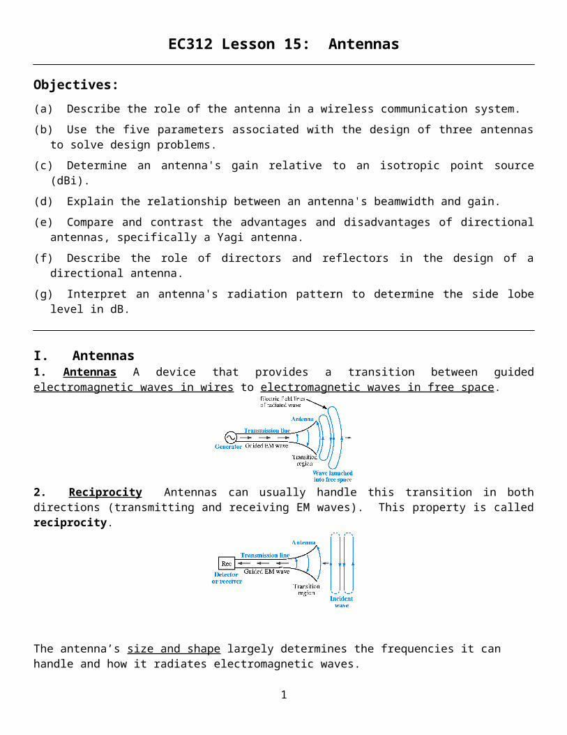
I. Antennas1. Antennas A device that provides a transition between guided electromagnetic waves in wires to electromagnetic waves in free space.
2. Reciprocity Antennas can usually handle this transition in both directions (transmitting and receiving EM waves). This property is called reciprocity.
The antenna’s size and shape largely determines the frequencies it can handle and how it radiates electromagnetic waves.
1

3. Antenna PolarizationThe polarization of an antenna refers to the orientation of the electric field it produces.
Polarization is important because the receiving antenna should have the same polarization as the transmitting antenna to maximize received power.
Types of PolarizationHorizontal Polarization
Vertical Polarization
4. Wavelength and AntennasRecall that wavelength () and frequency (f ) of an electromagnetic wave in free space are related by the speed of light (c). (c=3.0x10⁸ m/s)
The dimensions of an antenna are usually expressed in terms of wavelength ().Low frequencies imply long wavelengths, hence low frequency antennas are very large.High frequencies imply short wavelengths, hence high frequency antennas are usually small.
When selecting an appropriate antenna for a system, there are five key criteria that must be evaluated.1. Freq/Wavelength – determines which wireless standard (cellular, WiFi, terrestrial radio, or satellite communications) can be transmitted/received on the antenna.2. Gain – determines how concentrated the transmitted energy is in a particular direction (usually boresight). Higher gain means a stronger received signal, making it easier to communicate.3. Beam Pattern/Beamwidth – determines specifically where in space the antenna is sending energy. Important if you only want to send energy in a particular direction or want to avoid sending energy in a particular direction. Beamwidth can be measured either to the -3 dB (or half-power) point or the first null in the pattern.4. Bandwidth – determines the type of signal that can be transmitted by the antenna. Broadband signals transmit more data at a faster data rate, but broadband antennas are harder to design/build.5. Physical Size – Physically larger antennas have a higher gain and narrower beamwidth, but are much harder to conceal. And the system using the antenna may introduce its own constraints (no one wants to mount a 6 meter dish on the roof of their car).
2

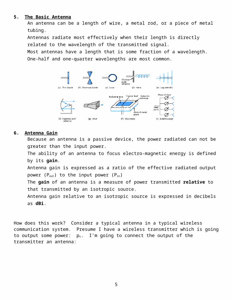
5. The Basic AntennaAn antenna can be a length of wire, a metal rod, or a piece of metal tubing.Antennas radiate most effectively when their length is directly related to the wavelength of the transmitted signal.Most antennas have a length that is some fraction of a wavelength.One-half and one-quarter wavelengths are most common.
6. Antenna GainBecause an antenna is a passive device, the power radiated can not be greater than the input power.The ability of an antenna to focus electro-magnetic energy is defined by its gain.Antenna gain is expressed as a ratio of the effective radiated output power (Pout) to the input power (Pin)The gain of an antenna is a measure of power transmitted relative to that transmitted by an isotropic source.Antenna gain relative to an isotropic source is expressed in decibels as dBi.
How does this work? Consider a typical antenna in a typical wireless communication system. Presume I have a wireless transmitter which is going to output some power: pt. I’m going to connect the output of the transmitter an antenna:
3
Now, if I had a perfect isotropic antenna, it would radiate that energy equally in all directions, and create a spherical wavefront: it is completely unfocused
Now, a perfect isotropic antenna really doesn’t exist. All real antennas will concentrate the energy of the wave in one or more directions:
Because we’re radiating the same amount of power, but in a smaller area, we say that the antenna has a gain associated with it, due to the fact that it’s concentrating the energy in a smaller area of space. Another way of thinking about this is a ratio of energy densities:
We can now define something called the effective radiated power (ERP or EIRP), which is the gain of an antenna (with respect to an isotropic radiator) multiplied by its input power. This represents the amount of power that the communication system would have produced if the antenna were a perfect isotropic radiator.
Hold that thought, because we’ll come back to it in the next lecture.Example A radio station has an ERP of 25kW and an input power of 1.73 kW. What is the gain of the antenna?
Note: Boresight is the axis of symmetry of the antenna. The antenna radiation pattern (the main lobe) is symmetrical about the boresight axis.
4
7. Antenna PatternFor many applications, we desire to focus the energy over a limited range. Directional antennas have this capability.
Advantages of a Directional Antenna
Because energy is only sent in the desired direction, the possibility of interference with other stations is reduced
The reduced beamwidth results in increased gain
Controlling the direction of the beam improves information security
Frequencies can be reused (wireless modems)
Directional antennas don’t work well in mobile situations and can be physically large
The antenna pattern is a plot that shows where (in space) the antenna is radiating energy. Typical plots are single cuts along the azimuth and elevation (horizontal and vertical planes), although a 3D plot is occasionally provided. The plots allow us to obtain valuable information about the antenna, including the beamwidth and side lobe level.
For example consider the highly directional antenna, with an azimuth (horizontal) and 3D pattern shown below.
From Frenzel, Principles of Electronic Communication Systems, McGraw Hill, 2008
The antenna beamwidth is measured to one of two places. The -3 dB beamwidth is measured using the radiation pattern. The circles indicate the relative strength of the signal as it moves away from the antenna in the center. The peak of the strongest lobe is usually given a value of 0 dB at 0 degrees and the rings can be 1dB apart. So as shown above, the beamwidth measures the points on the radiation curve that are 3 dB below the maximum level, on either side of the peak. The first null beamwidth is measured from the first null near the peak of the main lobe to the first null on the other side in the antenna’s pattern.
5

The Side Lobe Level (SLL) is a measure of how much energy the antenna is radiating in an off-axis direction. The Side Lobe Level is measured (in dB) from the peak of the main lobe to the peak of the side, or back, or lobe of interest (typically, but not always, the strongest lobe). This is also called the Front to Back Level for peak to back lobe.
SLL(dB) = Gboresight (dB) - Gsidelobe (dB)
Example
Considering the antenna:
From Frenzel, Principles of Electronic Communication Systems, McGraw Hill, 2008
1. What is the beamwidth of this directional antenna? 2. What is the side lobe level measured to the strongest side lobe? 3. What is the main lobe level measured to the back lobe?
4. Will a station located at (as indicated above) interfere with me? Will I interfere with it?
5. Will a station located at (as indicated above) be able to eavesdrop on my communications?
6. Suppose the receiver I am communicating with (at ) requires that the signal received by him be 1 pW. Will I have to transmit more power or less power than if I were using an omnidirectional antenna? Why?
6

II. Dipole AntennaOne of the most widely used antenna types is the half-wave dipole.The half-wave dipole, also called a doublet, is formally known as the Hertz antenna.A dipole antenna is two pieces of wire, rod, or tubing that are one-quarter wavelength long at the operating resonant frequency.We start with the magnetic and electric fields around a transmission line in (a) below, and from the ends we look at (b) electric field lines and (c) magnetic lines. The proximity of the conductors in a transmission line makes them poor radiators of EM waves as the electric field is contained and the magnetic field cancels each other out.
The half- wave dipole configuration allows a good transition of the EM waves in the transmission line to radiate in free space.
7

8

Three-dimensional radiation pattern for a dipole
Azimuth and elevation pattern for a dipole
1. Major Parameters for the Dipole Antenna
1. Freq/Wavelength – A dipole has a center frequency equal to λ.2. Beam Pattern/Beamwidth – A dipole has an omnidirectional pattern in the azimuth (energy is spread equally in all directions), a -3 dB beamwidth of 90º, or first-null beamwidth of 180º in the elevation (vertical) plane.3. Gain – A dipole has a gain of 2.15 dBi.4. Bandwidth – A dipole typically has a bandwidth that is ~25% of the center frequency.5. Physical Size – A dipole has a physical size equal to λ/2.
9

Example
A transmitter feeds a half-wave dipole antenna with 100 watts of power. Calculate the Effective Radiated Power (EIRP).
Example
How long would a dipole antenna be for AM 1100?
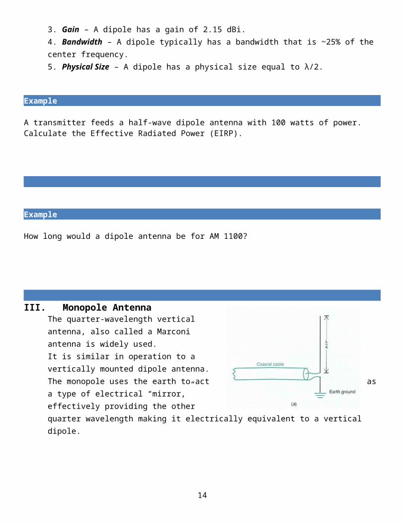
III. Monopole AntennaThe quarter-wavelength vertical antenna, also called a Marconi antenna is widely used.It is similar in operation to a vertically mounted dipole antenna.The monopole uses the earth to act as a type of electrical “mirror,” effectively providing the other quarter wavelength making it electrically equivalent to a vertical dipole.
10

1. Major Parameters for the Monopole Antenna
1. Freq/Wavelength – A monopole has a center frequency equal to λ.2. Beam Pattern/Beamwidth – A monopole has an omnidirectional pattern in the azimuth (energy is spread equally in all directions), a -3 dB beamwidth of 45º, or first-null beamwidth of 90º in the elevation (vertical) plane.3. Gain – A monopole has a gain of 1.6 dBi.4. Bandwidth – A monopole typically has a bandwidth that is ~10% of the center frequency.5. Physical Size – A monopole has a physical size equal to λ/4.
Example
The ballistic submarine, USS Alaska, has gone alert. They must stream an antenna to get their alert signal. If the alert signal is transmitted at 30 KHz, how far should they stream their antenna? (The antenna being streamed is a straight wire)
11

IV. Yagi (Yagi-Uda) Antenna
The Yagi-Uda was developed in Japan in 1926 by Professor Hidetsugu Yagi and his student Shintaro Uda. Their basic concept and structure is still used across a wide variety of modern antenna designs, and the Yagi is still the “go-to” antenna for high gain at VHF and UHF frequencies. There was a time when every home in America was equipped with a Yagi antenna. Do you know why?
A Yagi antenna is composed of a dipole antenna and multiple parasitic elements. These parasitic elements (known as reflectors and drivers) will resonate with the electric field produced by the dipole; judicious spacing of the parasitic elements will allow us to produce constructive interference and “push” energy in the forward direction.Here is a Yagi with one director and one reflector. This is a three-element Yagi.
The simplest Yagi, consisting of a driven element and one reflector, shown on the bottom of the prior page, has a gain of about 5 dBi.
12

1. More is BetterMore parasitic elements means more gain and narrower beamwidth.Adding more directors is more effective than adding more reflectorsThe greater the number of directors, the higher the gain and the narrower the beam angleHowever, we get diminishing returns as more elements are added.Most Yagi antennas have 1 reflector and 1-20 directors.
Example
What is the length of the driven element in a Yagi at 290 MHz?
Here’s an example pattern for a 900 MHz Yagi antenna produced by L-Com (Model HG909YE). The Yagi has 1 reflector and 4 drivers, and a gain of 9 dBi.
Let’s compare that to the L-Com Model HG914YE antenna,which has 1 reflector, 11 drivers, and 14 dBi of gain:
13
All else being equal, I’d rather have the higher gain, right? Well, unfortunately all else is not equal. The 9 dBi Yagi is only 26 inches long, perhaps a little large, but not unreasonable. The 14 dBi Yagi is a whopping 60 inches (that’s 5 full feet) long, more than double the physical size of the 9 dBi antenna.
Although the Yagi antenna does a good job at directing (and receiving) energy from the forward direction (in the main lobe), it has somewhat pesky side lobes. Thus, for a Yagi antenna, we are often interested in the ratio of the power radiated in the forward direction to the power radiated in the side lobes, particularly in the backward direction.The front-to-back ratio (F/B ratio) is the ratio of the power radiated in the forward direction to the power radiated in the backward direction. The F/B ratio is usually maximized versus Gain.
in dB Pf = Forward power
Pb = Backward power
If the radiation patterns are plotted in decibels, the F/B ratio is simply the difference between the forward value and the backward value,in dB. F/B= 12dB – (-3dB) = 15dB (above) (like the SLL).
2. Major Parameters for the Yagi Antenna
1. Freq/Wavelength – A Yagi will have a center frequency equal to λ, where is based on the length of the dipole radiator.2. Beam Pattern/Beamwidth – A Yagi is a directional antenna that transmits energy in a main lobe, but with fairly high side lobe levels. The beamwidth is dependent on the number of driver elements, with more drivers resulting in a narrower beamwidth.3. Gain – A Yagi’s gain is directly proportional to the number of driver elements, with typical gains in the range of 5-20 dBi.4. Bandwidth – A Yagi is typically very narrowband, with a bandwidth ~5% of the center frequency.
14

5. Physical Size – A Yagi’s dipole radiator has a physical size equal to λ/2, but the length is determined by the number of directors. Directors are typically spaced in half-wavelength increments.
You should be familiar with the five major parameters for the following three antennasDipoleMonopoleYagi-Uda
Assoc. Prof. Chris Anderson, LCDR Jesse Atwood, Prof. Currie Wooten, LCDR Jennie Wood
Help us improve these notes! Send comments, corrections and clarifications to [email protected]
15