Embed Size (px)
Citation preview

EC301 ManualOctober 2, 2014

Contents
1 General information 51.1 Safety and preparation for use . . . . . . . . . . . . . . . . . . . . . . . . . . . . . . . . . . . 51.2 Symbols you may find on SRS products . . . . . . . . . . . . . . . . . . . . . . . . . . . . . . 61.3 Specifications . . . . . . . . . . . . . . . . . . . . . . . . . . . . . . . . . . . . . . . . . . . . 71.4 Serial number and firmware revision . . . . . . . . . . . . . . . . . . . . . . . . . . . . . . . . 16
2 EC301 basics 172.1 Software . . . . . . . . . . . . . . . . . . . . . . . . . . . . . . . . . . . . . . . . . . . . . . . 172.2 Functional block diagram . . . . . . . . . . . . . . . . . . . . . . . . . . . . . . . . . . . . . . 172.3 Polarity convention . . . . . . . . . . . . . . . . . . . . . . . . . . . . . . . . . . . . . . . . . 192.4 Connecting the EC19 to the EC301 . . . . . . . . . . . . . . . . . . . . . . . . . . . . . . . . 19
2.4.1 Necessary Items . . . . . . . . . . . . . . . . . . . . . . . . . . . . . . . . . . . . . . 192.4.2 Steps . . . . . . . . . . . . . . . . . . . . . . . . . . . . . . . . . . . . . . . . . . . . 20
3 Operation 213.1 Front panel . . . . . . . . . . . . . . . . . . . . . . . . . . . . . . . . . . . . . . . . . . . . . 21
3.1.1 Power-on reset . . . . . . . . . . . . . . . . . . . . . . . . . . . . . . . . . . . . . . . 213.1.2 Bandwidth limit . . . . . . . . . . . . . . . . . . . . . . . . . . . . . . . . . . . . . . 223.1.3 CE limit . . . . . . . . . . . . . . . . . . . . . . . . . . . . . . . . . . . . . . . . . . 223.1.4 Cell . . . . . . . . . . . . . . . . . . . . . . . . . . . . . . . . . . . . . . . . . . . . . 223.1.5 External electrometer . . . . . . . . . . . . . . . . . . . . . . . . . . . . . . . . . . . 233.1.6 Voltage . . . . . . . . . . . . . . . . . . . . . . . . . . . . . . . . . . . . . . . . . . . 233.1.7 Current . . . . . . . . . . . . . . . . . . . . . . . . . . . . . . . . . . . . . . . . . . . 233.1.8 Mode . . . . . . . . . . . . . . . . . . . . . . . . . . . . . . . . . . . . . . . . . . . . 243.1.9 Rotating electrode . . . . . . . . . . . . . . . . . . . . . . . . . . . . . . . . . . . . . 243.1.10 Analog output . . . . . . . . . . . . . . . . . . . . . . . . . . . . . . . . . . . . . . . 253.1.11 Current range . . . . . . . . . . . . . . . . . . . . . . . . . . . . . . . . . . . . . . . 263.1.12 IR compensation . . . . . . . . . . . . . . . . . . . . . . . . . . . . . . . . . . . . . . 273.1.13 External input . . . . . . . . . . . . . . . . . . . . . . . . . . . . . . . . . . . . . . . 283.1.14 Measurement setup/control . . . . . . . . . . . . . . . . . . . . . . . . . . . . . . . . 293.1.15 Knob . . . . . . . . . . . . . . . . . . . . . . . . . . . . . . . . . . . . . . . . . . . . 293.1.16 Configure . . . . . . . . . . . . . . . . . . . . . . . . . . . . . . . . . . . . . . . . . . 303.1.17 Remote status . . . . . . . . . . . . . . . . . . . . . . . . . . . . . . . . . . . . . . . 31
3.2 Rear panel . . . . . . . . . . . . . . . . . . . . . . . . . . . . . . . . . . . . . . . . . . . . . . 323.2.1 Power entry . . . . . . . . . . . . . . . . . . . . . . . . . . . . . . . . . . . . . . . . 323.2.2 GPIB interface . . . . . . . . . . . . . . . . . . . . . . . . . . . . . . . . . . . . . . . 323.2.3 Ethernet interface . . . . . . . . . . . . . . . . . . . . . . . . . . . . . . . . . . . . . 333.2.4 Current interrupt synchronization . . . . . . . . . . . . . . . . . . . . . . . . . . . . 333.2.5 Timebase synchronization input . . . . . . . . . . . . . . . . . . . . . . . . . . . . . 333.2.6 Scan trigger input . . . . . . . . . . . . . . . . . . . . . . . . . . . . . . . . . . . . . 343.2.7 Program E/I output . . . . . . . . . . . . . . . . . . . . . . . . . . . . . . . . . . . 363.2.8 Scan synchronization output . . . . . . . . . . . . . . . . . . . . . . . . . . . . . . . 373.2.9 Auxiliary ADC inputs (1-3) . . . . . . . . . . . . . . . . . . . . . . . . . . . . . . . 383.2.10 Resistance temperature detector (RTD) input . . . . . . . . . . . . . . . . . . . . . 393.2.11 Grounding posts . . . . . . . . . . . . . . . . . . . . . . . . . . . . . . . . . . . . . . 403.2.12 Raw analog outputs . . . . . . . . . . . . . . . . . . . . . . . . . . . . . . . . . . . . 413.2.13 CE monitor . . . . . . . . . . . . . . . . . . . . . . . . . . . . . . . . . . . . . . . . 423.2.14 Synchronous ADC input . . . . . . . . . . . . . . . . . . . . . . . . . . . . . . . . . 43
4 Making cell connections 444.1 Floating operation . . . . . . . . . . . . . . . . . . . . . . . . . . . . . . . . . . . . . . . . . 45
4.1.1 Overview . . . . . . . . . . . . . . . . . . . . . . . . . . . . . . . . . . . . . . . . . . 454.1.2 Grounded Working Electrode . . . . . . . . . . . . . . . . . . . . . . . . . . . . . . . 46
2

Contents
4.1.3 Grounded Counter Electrode . . . . . . . . . . . . . . . . . . . . . . . . . . . . . . . 464.2 Working with grounded electrodes . . . . . . . . . . . . . . . . . . . . . . . . . . . . . . . . . 47
5 Performing scans using the front panel 505.1 Setting scan parameters – potentiostat mode . . . . . . . . . . . . . . . . . . . . . . . . . . . 50
5.1.1 Cyclic voltammetry (CV) . . . . . . . . . . . . . . . . . . . . . . . . . . . . . . . . . 505.1.2 Linear sweep voltammetry (LSV) . . . . . . . . . . . . . . . . . . . . . . . . . . . . 525.1.3 Steps . . . . . . . . . . . . . . . . . . . . . . . . . . . . . . . . . . . . . . . . . . . . 545.1.4 Holds . . . . . . . . . . . . . . . . . . . . . . . . . . . . . . . . . . . . . . . . . . . . 56
5.2 Setting scan parameters – galvanostat mode . . . . . . . . . . . . . . . . . . . . . . . . . . . 575.2.1 Cyclic current ramp . . . . . . . . . . . . . . . . . . . . . . . . . . . . . . . . . . . . 575.2.2 Linear current ramp . . . . . . . . . . . . . . . . . . . . . . . . . . . . . . . . . . . . 585.2.3 Current step . . . . . . . . . . . . . . . . . . . . . . . . . . . . . . . . . . . . . . . . 595.2.4 Current hold . . . . . . . . . . . . . . . . . . . . . . . . . . . . . . . . . . . . . . . . 60
5.3 Basic scan controls . . . . . . . . . . . . . . . . . . . . . . . . . . . . . . . . . . . . . . . . . 615.4 Triggering scans . . . . . . . . . . . . . . . . . . . . . . . . . . . . . . . . . . . . . . . . . . . 61
5.4.1 Triggering a scan from the front panel . . . . . . . . . . . . . . . . . . . . . . . . . . 615.4.2 Triggering a scan with the scan trigger input . . . . . . . . . . . . . . . . . . . . . . 615.4.3 Triggering a scan from the remote interface . . . . . . . . . . . . . . . . . . . . . . . 61
5.5 Setting the end of scan condition . . . . . . . . . . . . . . . . . . . . . . . . . . . . . . . . . 61
6 Using the EC301 with a frequency response analyzer (FRA) 63
7 Remote programming 647.1 Command syntax . . . . . . . . . . . . . . . . . . . . . . . . . . . . . . . . . . . . . . . . . . 647.2 Argument formats . . . . . . . . . . . . . . . . . . . . . . . . . . . . . . . . . . . . . . . . . . 647.3 Detailed command list . . . . . . . . . . . . . . . . . . . . . . . . . . . . . . . . . . . . . . . 65
7.3.1 Firmware and hardware revisions . . . . . . . . . . . . . . . . . . . . . . . . . . . . 657.3.2 Program E/I setup (with external input) . . . . . . . . . . . . . . . . . . . . . . . . 657.3.3 Control loop commands . . . . . . . . . . . . . . . . . . . . . . . . . . . . . . . . . . 687.3.4 Cell switch . . . . . . . . . . . . . . . . . . . . . . . . . . . . . . . . . . . . . . . . . 707.3.5 IR compensation . . . . . . . . . . . . . . . . . . . . . . . . . . . . . . . . . . . . . . 717.3.6 Scan trigger commands . . . . . . . . . . . . . . . . . . . . . . . . . . . . . . . . . . 737.3.7 Rotating working electrode commands . . . . . . . . . . . . . . . . . . . . . . . . . 747.3.8 Analog output commands . . . . . . . . . . . . . . . . . . . . . . . . . . . . . . . . . 757.3.9 Voltage (E) measurement setup . . . . . . . . . . . . . . . . . . . . . . . . . . . . . 777.3.10 Current (I) measurement setup . . . . . . . . . . . . . . . . . . . . . . . . . . . . . 787.3.11 Reading single measurement results . . . . . . . . . . . . . . . . . . . . . . . . . . . 807.3.12 Streaming data . . . . . . . . . . . . . . . . . . . . . . . . . . . . . . . . . . . . . . 827.3.13 Remote interface commands . . . . . . . . . . . . . . . . . . . . . . . . . . . . . . . 867.3.14 Timebase commands . . . . . . . . . . . . . . . . . . . . . . . . . . . . . . . . . . . 897.3.15 Status reporting commands . . . . . . . . . . . . . . . . . . . . . . . . . . . . . . . . 907.3.16 Pulsed waveform generation commands . . . . . . . . . . . . . . . . . . . . . . . . . 1007.3.17 Ramp generation commands . . . . . . . . . . . . . . . . . . . . . . . . . . . . . . . 1067.3.18 Arbitrary waveform generation commands . . . . . . . . . . . . . . . . . . . . . . . 1117.3.19 Reading temperature measurements . . . . . . . . . . . . . . . . . . . . . . . . . . . 116
7.4 Programming examples . . . . . . . . . . . . . . . . . . . . . . . . . . . . . . . . . . . . . . . 1177.4.1 Normal pulse . . . . . . . . . . . . . . . . . . . . . . . . . . . . . . . . . . . . . . . . 1177.4.2 Cyclic voltammetry . . . . . . . . . . . . . . . . . . . . . . . . . . . . . . . . . . . . 1187.4.3 Current interrupt IR compensation . . . . . . . . . . . . . . . . . . . . . . . . . . . 1197.4.4 Arbitrary waveform . . . . . . . . . . . . . . . . . . . . . . . . . . . . . . . . . . . . 120
Bibliography 121
A Measuring cell voltages at the cell 122
3

Contents
B Pinouts 124B.1 Cell interface (25 pins) . . . . . . . . . . . . . . . . . . . . . . . . . . . . . . . . . . . . . . . 124B.2 RTD interface (5 pins) . . . . . . . . . . . . . . . . . . . . . . . . . . . . . . . . . . . . . . . 124
C Major symbols and abbreviations 126
Alphabetical command index 127
4

1 General information
1 General information
1.1 Safety and preparation for use
WarningDangerous voltages, capable of causing injury or death, are present in this instrument. Useextreme caution whenever the instrument covers are removed. Do not remove the covers whilethe unit is plugged into a live outlet.
Line fuseVerify that the correct line fuse(s) are installed before connecting the line cord. Fuse size is 3AB/3AG“slo-blo” (φ6.3 × 32mm). For 100V/120V, use a single 3A fuse; for 220V/240V, use two 1.5A fuses.
Line cordThe EC301 has a detachable, three-wire power cord for connection to the power source and to a protectiveground. The exposed metal parts of the instrument are connected to the outlet ground to protect againstelectrical shock. Always use an outlet which has a properly connected protective ground.
ServiceDo not attempt to service or adjust this instrument unless another person, capable of providing first aid orresuscitation, is present.
Do not install substitute parts or perform any unauthorized modification to this instrument. Contact thefactory for instructions on how to return the instrument for authorized service and adjustment.
5 EC301 Potentiostat/Galvanostat/ZRA

1 General information 1.2 Symbols you may find on SRS products
1.2 Symbols you may find on SRS products
Symbol Description
Alternating current
Caution - risk of electric shock
Frame or chassis terminal
Caution - refer to accompanying documents
Earth (ground) terminal
Battery
Fuse
On (supply)
Off (supply)
6 EC301 Potentiostat/Galvanostat/ZRA

1 General information 1.3 Specifications
1.3 Specifications
Voltage and current measurement accuracy
• Voltage measurement accuracy
±0.2% of reading (VRE −VWE SENSE)± 5mV
• Current measurement accuracy, 1A range
±0.5% of reading (IWE)± 0.2% of range
• Current measurement accuracy, other ranges
±0.2% of reading (IWE)± 0.2% of range
• Power amplifier
– Compliance voltage
≥ ±30V full compliance
– Maximum output current
≥ ±1A
– Slew rate (power amplifier in isolation)
≥ 10V/µs
– Output short-circuit protected
7 EC301 Potentiostat/Galvanostat/ZRA

1 General information 1.3 Specifications
Potentiostat mode
• Applied potential accuracy:
Potential versus reference within Accuracy
±5V ±0.2% of setting ± 5mV±10V ±0.5% of setting ± 5mV±15V ±1% of setting ± 5mV
• Applied potential resolution:
Mode Resolution
General (potential set with thumbwheel or remote interface) 500µVPerforming an automatic scan (CV or LSV) 200µV
• Noise and ripple
< 20µVrms (1Hz → 10kHz)
• Applied E range
±15V versus reference (|CE| <30V versus signal ground)
8 EC301 Potentiostat/Galvanostat/ZRA

1 General information 1.3 Specifications
Galvanostat mode
• Applied current accuracy:
±0.5% of setting ±0.2% of current range, 1A range
±0.2% of setting ±0.2% of current range, all other ranges
ZRA mode
• Voltage offset
CE sense and WE sense electrodes held within 5mV of each other
• Output current
1A range: −1A min, +1A max
All other ranges: −2× full scale min, +2× full scale max
9 EC301 Potentiostat/Galvanostat/ZRA

1 General information 1.3 Specifications
General control loop
• Bandwidth control
Bandwidth limits10Hz, 100Hz, 1kHz, 10kHz, 100kHz, >1MHz(10kΩ resistive load, < 100µA output cur-rent)
• Compliance limiting
Voltage limit accuracy
Cell current(ICE
)Accuracy
≤10mA ±250mV≤1A ±1V
10 EC301 Potentiostat/Galvanostat/ZRA

1 General information 1.3 Specifications
IR compensation
• Current interrupt
Switching time (on → off) < 5µs (1 kΩ resistive load)Interrupt time 100µs → 1sInterrupt frequency 0.1 Hz → 300 Hz
• Positive feedback
Range
Irange Ru
1 A 0 → 3 Ω100 mA 0 → 30 Ω10 mA 0 → 300 Ω1 mA 0 → 3 kΩ100 µA 0 → 30 kΩ10 µA 0 → 300 kΩ1 µA 0 → 3 MΩ100 nA 0 → 30 MΩ10 nA 0 → 300 MΩ1 nA 0 → 3 GΩ
Resolution1mΩ for 1A range1MΩ for 1nA range
11 EC301 Potentiostat/Galvanostat/ZRA

1 General information 1.3 Specifications
General system
• Remote interfaces
LAN (10/100 base-T Ethernet)
GPIB (IEEE-488)
• Dimensions (W × H × D)
– Main box
17 × 18.5 × 5.25 inches
– External box
3.25 × 4.75 × 2.5 inches
– Umbilical
36 inches
– Weight
– Power
• RTD measurement
– Temperature sensor
User supplied 100Ω Pt RTD, α = 0.00385 Ω/Ω/
– Range
−100 to +200
– Resistance measurement accuracy
±0.3Ω
12 EC301 Potentiostat/Galvanostat/ZRA

1 General information 1.3 Specifications
Front panel connectors
• External input
±15V analog input in potentiostat mode, ±2V in galvanostat mode
Input impedance: 10kΩ ‖ 50pF
• Rotating electrode output BNC
0→10V analog output
Accuracy: ±1% of setting ±5mV
Output impedance: 10Ω
10mA max output current
• Voltage (E) output BNC
±15V analog output
Accuracy: ±0.2% of VRE −VWE Sense ± 5mV
Output impedance: 50Ω
10mA max output current
• Current (I) output BNC
±2V analog input
Accuracy: IWE within ±0.5% of (VBNC × Irange)± 0.2%× Irange, 1 A range
Accuracy: IWE within ±0.2% of (VBNC × Irange)± 0.2%× Irange, other ranges
Output impedance: 50Ω
10mA max output current
13 EC301 Potentiostat/Galvanostat/ZRA

1 General information 1.3 Specifications
Rear panel connectors
• Timebase input BNC
Frequency: 10MHz
Level: 1Vpp (nominal)
• TTL measurement synchronization BNCs
Current interrupt and scan synchronization outputs, scan trigger input
• Program E/I output BNC
±15V analog output
Accuracy: ±0.2% of total program voltage (internal sources + external input) ± 5mV
Output impedance: 10Ω
10mA max output current
• Auxiliary ADC input BNCs
Three ±10V analog to digital inputs
input impedance: 100kΩ
1mV resolution
• Signal / floating ground banana jacks
Signal ground ohmically connected to chassis ground
Floating ground can float ±8V relative to signal ground
Signal/floating ground isolation: 10MΩ
• RTD input
5-pin connector for Pt RTD temperature probe
• Raw E output BNC
±15V analog output
Accuracy: ±0.2% of VRE −VWE SENSE ± 5mV
Output impedance: 50Ω
10mA max output current
• Raw I output BNC
±2V analog input
Accuracy: IWE within ±0.5% of (VBNC × Irange)± 0.2%× Irange, 1 A range
Accuracy: IWE within ±0.2% of (VBNC × Irange)± 0.2%× Irange, other ranges
Output impedance: 50Ω
10mA max output current
• CE/3 output BNC
±10V analog output
Accuracy: ±1% of VCE/3 ± 10mV
Output impedance: 50Ω
10mA max output current
14 EC301 Potentiostat/Galvanostat/ZRA

1 General information 1.3 Specifications
• Synchronous ADC input
Sampled synchronously with E and I ADCs
±10V analog to digital input
input impedance: 100kΩ
16-bit resolution
• Ethernet interface
• IEEE 488 interface
• Chassis ground
• Power entry module
15 EC301 Potentiostat/Galvanostat/ZRA

1 General information 1.4 Serial number and firmware revision
Differential electrometer
• Input impedance
> 1TΩ ‖ 20pF
• Input bias current
< 20pA
• Common-mode rejection ratio (CMRR)
Bandwidth CMRR (dB)
10 kHz 80 (90 typ.)100 kHz 60 (70 typ.)
• Bandwidth
> 10MHz
Cell current input (WE)
• Ranges
10 decades – 1A to 1nA
• Frequency response
1.4 Serial number and firmware revision
• Serial number
If you need to contact Stanford Research Systems, please have the serial number of your unitavailable. The 5-digit serial number is printed on a label affixed to the rear panel. the unit is poweredon. The serial number can also be displayed on the front panel after the unit is powered on by pressingthe [DISPLAY] key.
• Firmware revision
The firmware revision code is shown on the front panel when the unit is powered on.
16 EC301 Potentiostat/Galvanostat/ZRA

2 EC301 basics
2 EC301 basics
2.1 Software
The EC301 is intended to operate with the SRSLab Windows software package. SRSLab can be downloadedfrom the SRS web site, www.thinkSRS.com. Complete instructions for SRSLab, in the form of documentationvideos, are also available on the website.
2.2 Functional block diagram
Figure 1 illustrates the major signal paths in the EC301.
17 EC301 Potentiostat/Galvanostat/ZRA

Erroramplifier
WE
Differenceamplifiers
Currentto
voltage
Potentiostat,galvanostat,or ZRA mode
Σ
Positivefeedbacklevel
Local feedback /bandwidth control Compliance
limits
Voltageclamp
Poweramplifier
10 Hzlowpass
Anti−alias
E output(front panel)
Σ
Bias rejection10 Hzlowpass
(rear panel)Raw E output
10 Hzlowpass
Anti−alias
Voltagemeasurement
Currentmeasurement
I output(front panel)
Σ
Bias rejection10 Hzlowpass
(rear panel)Raw I output
ΣExternalinput
generationInternal scan
− 1
Galvanostat mode
Potentiostat mode
Program E/Ioutput
− 1
Galvanostat mode
Potentiostat mode
ProgramADC
Program E/Imeasurement
13
+
CE/3output
CE voltagemeasurementCE ADC
Current interruptcell switch
Front panelsafety switch RE
WE sense
Cell CE sense
CE
E ADC
I ADC
Figure 1: EC301 block diagram.

2 EC301 basics 2.3 Polarity convention
2.3 Polarity convention
The relative polarity of voltages and currents handled by the EC301 follows the American polarity convention.As illustrated in Fig. 2, this convention calls for cathodic (reducing) currents to be taken as positive. Voltagesare programmed taking RE as the reference potential, so asking for +1V with the external input or the frontpanel will move the WE potential +1V above RE. We invert the polarity of the front and rear panel VOLTAGEoutputs relative to the front panel display in order to accommodate frequency response analyzers (FRAs).
V
RE
WE
Potentiostat modeMore anodic (oxidizing)
input BNCExternal Oxidation (anodic) current
has negative sign
OV
+1V
Externalinput BNC
V RE
WE
Galvanostat modeMore cathodic (reducing)
Reduction (cathodic) currenthas positive sign
+1V
OV
0V
CE/3 −1/3V
Voltages and currents for 1 ohm resistive cell withCE connected to RE
VOLTAGE
V
0V
+1V
CURRENT
A
0A
+1A
VOLTAGE
0V
−1V
V
CURRENT
0A
−1A
A
CE/3 0V
+1/3V
Front panel displaysBNC outputs
Figure 2: The EC301 uses the American polarity convention when applying voltages and currents.
2.4 Connecting the EC19 to the EC301
Before you do any electrochemical measurements with the EC301, you must first connect the EC19.
2.4.1 Necessary Items
In order to connect an EC19 to an EC301, you will need a flat blade screwdriver, and the umbilical cable.All items except the flat bladed screwdriver were provided in your EC301 shipment. Each item is picturedin Fig. 3.
Figure 3: From left to right: EC19, umbilical cable, EC301, flat blade screwdriver.
19 EC301 Potentiostat/Galvanostat/ZRA

2 EC301 basics 2.4 Connecting the EC19 to the EC301
2.4.2 Steps
1. Identify the connection points on the EC19. There are two jack screws on the rear panel of the unit,shown in Fig. 4.
Figure 4: EC19 rear panel connector. Securing the umbilical cable.
2. Screw the umbilical cable screws into the jack screws of the EC19 as shown in Fig. 4.
3. Identify the connection points on the EC301. There are two jack screws on the front panel of the unit,shown in Fig. 5.
Figure 5: Front panel umbilical connector on EC301. Securing the umbilical cable to the EC301.
4. Screw the umbilical cable screws into the jack screws of the EC301 as shown in Fig. 5.
5. Power up the EC301 (switch is on rear panel). If you get any front panel errors about the EC19, turnoff the EC301. Check the umbilical connection on both ends and power up the EC301 again. If errorspersist, contact SRS.
20 EC301 Potentiostat/Galvanostat/ZRA

3 Operation
3 Operation
This manual will refer to a key with brackets such as [Key].
3.1 Front panel
AUTORANGE
15 V POTENTIOSTAT
µΑ100
µΑ10
µΑ1
Ωk
E 1 / I 1
T1
T2
E 2 / I 2E 1 I1
µA
+
+
kΩ10 50 pF
10 mA
1 mA
1 A
100 mA
100 nA
10 nA
1 nA
CURRENT RANGE
VOLTAGE
OUTPUTSLOAD WITH 10
50 Ω
10 HzLOW PASS
FILTER
CURRENT
REJECTIONBIAS
ANALOG OUTPUT
0−10V
SET
ROTATING ELECTRODE
MODE
POTENTIOSTAT
GALVANOSTAT
ZRA
CALIBRATE
MODE
ENABLE
30V/1A MAX COMPLIANCE
CELL
BANDWIDTH LIMIT
100 kHz
1 MHz
10 kHz
1 kHz
100 Hz
10 Hz
CE LIMIT VOLTAGE OVERLOAD CURRENT OVERLOAD
IR COMPENSATION
EC301 POTENTIOSTAT / GALVANOSTAT / ZRA TRACKING
CONFIGUREMEASUREMENT SETUP / CONTROL
EXTERNAL INPUTREMOTE STATUS
ENABLE
INTERRUPT
FEEDBACK
MODE SET
LSV
MODE
RATE
SET
GO/ARM PAUSE
ADVANCE STOPSTOP
STANFORD RESEARCH SYSTEMS
OPEN CIRCUIT
SCAN
ENDS AT
SINGLE
CONTINUOUS
SCAN
TYPE
EXTERNAL
MANUAL
TRIGGER
SRQ
REMOTE MODE
ERROR
EXT TIMEBASE
ACTIVITY
LOCAL
GPIBCV
STEP
HOLD
TIMEDHOLD
GPIB TCP/IP DISPLAY
ENTER
ENABLE
SET LIMIT
LIMITING
V
A
mA
nA
DIRECTCONTROL
ADD TOSCAN
2 V GALVANOSTAT
CE RE WE
WESIGNAL
CESENSE SENSE
GROUND
3.1.1 Power-on reset
ACTIVITY
ERROR
EXT TIMEBASE
REMOTE MODE
LOCALSRQ
REMOTE STATUS
To restore the instrument to its factory-default settings from thefront panel, hold down the [LOCAL] key while the power is turnedon.
21 EC301 Potentiostat/Galvanostat/ZRA

3 Operation 3.1 Front panel
3.1.2 Bandwidth limit
BANDWIDTH LIMIT
100 kHz
1 MHz
10 kHz
1 kHz
100 Hz
10 Hz
Use the [∧] and [∨] keys to increase or decrease the control band-width.
3.1.3 CE limit
LIMITING
SET LIMIT
CE LIMIT
ENABLE
The counter electrode (CE) voltage relative to ground can be lim-ited to protect sensitive cells. Using the [ENABLE] key to enterthe limiting mode allows reducing the maximum CE voltage from±500mV to ±30 V. This maximum is adjusted by pressing the [SETLIMIT] key and turning the knob. The tracking light will indicatethat the CE limit follows the knob movement.
3.1.4 Cell
ENABLE
30V/1A MAX COMPLIANCE
CELL
The external electrometer should be connected to the main boxusing this DB-25 connector. The umbilical should be securely fas-tened to this connector using the jack screws on either side.
Use the [ENABLE] switch to manually disconnect the CE fromthe power amplifier whenever you must come in contact with thecell electrodes. This switch is illuminated when the CE is connectedto the control circuitry. When this switch is “in,” the instrumentconnects or disconnects the CE as needed. When “out,” the CE isalways disconnected and the switch is dark.
22 EC301 Potentiostat/Galvanostat/ZRA

3 Operation 3.1 Front panel
3.1.5 External electrometer
CE RE WE
WESIGNAL
CESENSE SENSE
GROUND
The external electrometer face contains the counter electrode (CE)output, three electrometer inputs, the working electrode (WE) cur-rent input, and a grounded binding post. See section 4 for il-lustrations of how these inputs and outputs are used in differentinstrument modes.
CE (counter electrode) output: This is the output of the EC301’scontrol amplifier. It can source or sink 1A into a -30V to +30Vrange.
CE SENSE input: This electrometer input is used with WE SENSE in ZRA mode to monitor the voltage betweentwo typically identical electrodes. As shown in figure 12, it is named for usually being connected to the CE
output.
RE (reference electrode) input: As illustrated in figure 1, this electrometer input is used with WE SENSE tomonitor cell potentials.
WE SENSE input: As illustrated in figure 1, this electrometer input is used with both the RE and CE SENSE
electrodes to monitor cell potentials.
WE input: This input connects to a shunt resistor used to measure current flowing in the working electrode.The input resistance here will vary with the current range setting.
SIGNAL GROUND: This can be connected to a Faraday cage to isolate sensitive cells from electrical noise.
3.1.6 Voltage
VOLTAGE OVERLOAD
V
This display shows the results of the internal VWE SENSE −VRE
measurement. The OVERLOAD light indicates when the cell potentialexceeds ±15 V relative to signal ground. Measurement accuracywill degrade from specifications outside of this range.
3.1.7 Current
mA
nA
CURRENT
Aµ
OVERLOAD
A
This display shows the results of the internal cell current mea-surement. The OVERLOAD light indicates when current exceeds±2×Irange or 1A, where Irange is the current range in use. Measure-ment accuracy will degrade from specifications during overloads.
23 EC301 Potentiostat/Galvanostat/ZRA

3 Operation 3.1 Front panel
3.1.8 Mode
POTENTIOSTAT
GALVANOSTAT
ZRA
CALIBRATE
MODE
MODE
Use the [MODE] key to cycle the EC301 through its various oper-ating modes.
POTENTIOSTAT: control potential and measure current. In thismode, the EC301 controls the potential of the working relative tothe reference electrode. The counter electrode is driven to whateverpotential is necessary (within the ±30 V or the user-imposed com-pliance limits) to hold VWE SENSE −VRE at the control (program)voltage.
GALVANOSTAT: control current and measure potential. In this mode, the EC301 controls cell current flowingthrough the working electrode. The counter electrode is driven to whatever potential is necessary to holdthis current at the programmed value.
ZRA (Zero-resistance ammeter): hold two electrodes at the same potential. In this mode, the EC301 holdsthe counter and working electrodes at the same potential while current flows between them. Current flowwith no potential drop implies no resistance – hence the name of the mode. The relative potential is sensedwith the WE SENSE and CE SENSE connections, and the counter electrode is driven to hold this potential atzero.
CALIBRATE: This function is reserved for use by the factory.
3.1.9 Rotating electrode
ROTATING ELECTRODE
0−10V
SET
This DC voltage output can be used with an external control unitto control the speed of rotating working electrodes. Use the [SET]key to adjust the output voltage within 0 → 10V.
This output can source a maximum of 10 mA. The input impedance of the external controlunit must be larger than 1 kΩ to achieve the maximum 10 V output.
24 EC301 Potentiostat/Galvanostat/ZRA

3 Operation 3.1 Front panel
3.1.10 Analog output
10 ΩOUTPUTS
LOAD WITH 50 Ω
10 HzLOW PASS
FILTER
CURRENT
REJECTIONBIAS
ANALOG OUTPUT
VOLTAGE
k
This section contains the VOLTAGE and CURRENT analog outputsas well as the [BIAS REJECTION] and [10 Hz LOWPASS FILTER]
controls for modifying the outputs.
VOLTAGE output (EBNC): This output is the potential of the ref-erence electrode with respect to the working electrode, optionallysubjected to a 10 Hz lowpass filter and/or bias rejection. The ±15V output range is the same as the maximum polarization range.
CURRENT output (IBNC): This output is proportional to currentflowing in the working electrode (IWE), optionally subjected to a10 Hz lowpass filter and/or bias rejection. The output voltage isgiven by
IBNC = 1V×IWE
Irange
where Irange is the current range in use (1 mA, 10 mA, etc.). As described in section 2.3, IBNC becomesmore positive when current flows into the working electrode (cathodic current).
The polarity at the VOLTAGE BNC output (EBNC) is opposite that reported on the frontpanel displays. The voltage is thus EBNC = VRE −VWE SENSE. We invert the polarity hereto correct the sign of the cell impedance Zcell calculated with
Zcell =EBNC
Irange × IBNC
where Irange is the current range in use and IBNC is the voltage at the CURRENT BNC output.See figure 2 for an illustration of BNC versus display polarities.
[BIAS REJECTION]: Bias rejection attempts to subtract off the DC component of the analog output voltages.This can be useful when making AC response measurements in the presence of a DC hold. Removing the DCcomponent of a signal can allow the use of more sensitive input ranges on external equipment like frequencyresponse analyzers.
When [BIAS REJECTION] is pushed, the EC301 will immediately average VRE −VWE SENSE and IWE
over a 1s window. It will then subtract those average values from all subsequent front panel EBNC and IBNC
outputs. The averages will not update until bias rejection is turned off and then back on. Note that the RAWE and RAW I outputs on the rear panel always provide the VRE −VWE SENSE and IWE measurements withno filtering or bias rejection.
Bias rejection affects both analog outputs simultaneously when engaged from the front panel,but can be limited to either output when set up using the remote interface. The individualrejection levels can also be set arbitrarily instead of being automatically detected. See section7.3.8 on page 75 for the appropriate remote commands.
Neither changing the current range nor enabling autoranging is allowed while bias rejectionis active.
25 EC301 Potentiostat/Galvanostat/ZRA

3 Operation 3.1 Front panel
[10 Hz LOW PASS FILTER]: Use this key to simultaneously filter both the VOLTAGE and CURRENT analogoutputs. The front panel filter has a 6 dB/octave rolloff with a -3 dB frequency of 10 Hz.
You can customize filter settings using the lpfili and lpfile commands described insection 7.3.8. These commands allow filtering a single output instead of both. Note that the[10 Hz LOW PASS FILTER] key will light whenever filtering is applied to either output.
3.1.11 Current range
AUTORANGE
1 nA
100
10 Αµ
µΑ1
CURRENT RANGE
Α
10 mA
1 mA
1 A
100 mA
100 nA
10 nA
µ
Use the [∧] and [∨] keys to select a current range. A cell current(IWE) equal to the selected current range (IWE = Irange) gives 1 Vat the CURRENT output BNC (IBNC = 1 V). Likewise, 1 V appliedto the EXTERNAL INPUT BNC in galvanostat mode will generate acontrolled current of Irange.
Currents exceeding±2×Irange or±1 A will generate an overloadcondition. While the EC301 can accept currents ≤ ±1 A in anyrange without damage, measurement accuracy is degraded duringoverloads.
Use the [AUTO RANGE] key to toggle automatic selection ofIrange based on the measured cell current. Note that auto-rangingis not allowed in galvanostat mode.
26 EC301 Potentiostat/Galvanostat/ZRA

3 Operation 3.1 Front panel
3.1.12 IR compensation
IR COMPENSATION
ENABLE
INTERRUPT
FEEDBACK
MODE SET
IR compensation involves adding an “extra” voltage to the control(program) voltage to compensate for drops between RE and WE.Use the [MODE] key to toggle between two ways of generating thisvoltage: positive feedback and current interrupt. Compensationwill not be applied until the [ENABLE] key is pressed.
INTERRUPT mode: Figure 6 illustrates the parameters used for cur-rent interrupt when engaged from the front panel. In this mode,the CE is periodically disconnected from the control electronics tointerrupt the cell current. This removes any IR drop between thereference and working electrodes, causing |VWE SENSE − VRE| to
drop by ∆Vir. The EC301 then takes two samples of |VWE SENSE − VRE| to measure this drop – one afterinterruption, and one after control is restored. This value, along with the percent correction factor, is usedto calculate the boost potential ∆Vb added to the program voltage.
∆ Vb
VWE SENSE − VRE
topentdc
tdo V ir∆
tp
µs<10
Time
Second interruption cycle
Figure 6: Cell potentials during current interrupt IR compensation. Default values for the various parametersare shown in table 1.
Use the [SET] key in INTERRUPT mode to adjust the percent correction factor – the only parameter thancan be set from the front panel. The other parameters shown in figure 6 are set to the default values shownin table 1.
Parameter Default value Remote command
tp 100 ms (10 Hz) ciperd (see page 72)topen 200µs ciopen (see page 71)tdo 120µs
cidlay (see page 72)tdc 200µs
Table 1: Default values for current interrupt parameters. These values are used when current interrupt isengaged using the front panel.
27 EC301 Potentiostat/Galvanostat/ZRA

3 Operation 3.1 Front panel
The current interrupt parameters can be adjusted away from their default values using theremote interface. See section 7.4.3 on page 119 for an example.
FEEDBACK mode: Positive feedback IR compensation adds a boost voltage IWE×Ru to the program voltage,where Ru is the uncompensated resistance parameter.
Use the [SET] key in FEEDBACK mode to adjust Ru. The allowed ranges for Ru in each current range areshown in table 2.
Irange Ru
1 A 0 → 3 Ω100 mA 0 → 30 Ω10 mA 0 → 300 Ω1 mA 0 → 3 kΩ100 µA 0 → 30 kΩ10 µA 0 → 300 kΩ1 µA 0 → 3 MΩ100 nA 0 → 30 MΩ10 nA 0 → 300 MΩ1 nA 0 → 3 GΩ
Table 2: Allowed Ru ranges for each current range.
3.1.13 External input
kΩ10 50 pF
++ 2 V GALVANOSTAT
15 V POTENTIOSTAT
EXTERNAL INPUT
DIRECTCONTROL
ADD TOSCAN
The EC301 can take its control voltage directly from the externalanalog input, allowing its use with function generators and fre-quency response analyzers. These control voltages can be used bythemselves or added to internally-generated scans.
In potentiostat mode, voltages applied at the external inputwill be applied to the cell according to the American Polarity Con-vention described in section 2.3. This input has unity gain: +1 Vapplied at the input will change (VWE SENSE − VRE) by +1 V. Theinput thus accepts the full ±15 V allowed polarization range.
In galvanostat mode, controlled current is given by
IWE = Irange
(Vext + Vprog
1V
)
where Vext is the voltage applied at the external input and Vprog is the internally-generated program voltage.Currents greater than 2× Irange or 1 A will generate overloads, so the external input’s range in this mode is±2 V for Irange < 1 A, and ±1 V for Irange = 1 A. The polarity is again taken from the American PolarityConvention described in section 2.3.
Use the [ADD TO SCAN] key to toggle adding the external input voltage to internally-generated scans orholds. This key leaves engaging the control loop (lighting the CELL button) up to the scan controls.
Use the [DIRECT CONTROL] key if potentials or currents to be applied to the cell come only from theexternal input. If the cell is enabled (via the CELL button), [DIRECT CONTROL] engages or disengages thecontrol loop, taking control voltages or currents solely from the external input.
The external input is ignored (taken as 0 V) if both the [ADD TO SCAN] and [DIRECT CONTROL] lightsare dark.
28 EC301 Potentiostat/Galvanostat/ZRA

3 Operation 3.1 Front panel
3.1.14 Measurement setup/control
E 1 / I1
T1
T2
E 2 / I2E 1 I1
LSV
RATE
SET
OPEN CIRCUIT
SINGLE
CONTINUOUS
EXTERNAL
MANUAL
CV
STEP
HOLD
TIMEDHOLD
SCANENDS AT
SCANTYPE
TRIGGER
PAUSEGO/ARM
STOPADVANCEMODE
MEASUREMENT SETUP / CONTROL
A variety of automatic scans and holds can be programmed from the EC301’s front panel. Once the scantype is selected, you will be prompted for a set of necessary parameters. When [GO/ARM] is pressed witha MANUAL trigger setting, the EC301 will engage control, apply the scan, and remove control as required bythe scan end condition.
Use the [MODE] key to select a scan type. These types are described in section 5 on page 50.Use the [TRIGGER] key to select the action of [GO/ARM]. In MANUAL mode, the programmed scan will
begin when [GO/ARM] is pressed. In EXTERNAL mode, pressing [GO/ARM] will “arm” the EC301 – preparingit to scan with the next rising or falling edge received at the rear panel SCAN TRIGGER input. This allowsthe scan to be triggered by other experimental events. See section 3.2.6 on page 34 for more informationabout the SCAN TRIGGER input.
3.1.15 Knob
TRACKING
Use the knob to enter numbers via the character display. The knobis velocity-sensitive, so experiment with different rotation speeds toset large numbers.
The TRACKING indicator will light when turning the knob willimmediately affect cell conditions. For example, if a hold has beenengaged from the front panel (control loop is engaged – big redCELL button is lit) and the [SET] key is pressed to adjust E1/I1,TRACKING will light to indicate that cell polarization is moving with
the knob. This allows manually adjusting polarization while observing other cell characteristics – “thumb-wheel scanning.”
Most parameters can be “locked in” by re-pushing the same key used to set them. For example, pushing[SET] once to adjust the E1 of a hold will allow will allow E1 to be freely changed with the knob. Pushing[SET] again will lock the value in and disable the knob. The value will also be locked in if a [SET] key fromanother section is pressed. In general, moving on to another setting will lock the previous one.
29 EC301 Potentiostat/Galvanostat/ZRA

3 Operation 3.1 Front panel
3.1.16 Configure
GPIB DISPLAY
ENTER
CONFIGURE
GPIB TCP/IP
Use this section to configure the remote interface (LAN, GPIB)and to cycle through the various display modes.
30 EC301 Potentiostat/Galvanostat/ZRA

3 Operation 3.1 Front panel
3.1.17 Remote status
ACTIVITY
ERROR
EXT TIMEBASE
REMOTE MODE
LOCALSRQ
REMOTE STATUS
The indicators in this section describe the status of the remote(GPIB or LAN) interface and the external timebase.
SRQ: This indicator is on whenever a service request (SRQ) is gener-ated by the EC301. It will stay on until the status register (INSR,MESR, or *ESR) causing the SRQ is cleared. See figure 29 onpage 99 for a description of how status bit values are promoted tocause SRQs.
ACTIVITY: This indicator flashes when there is activity on the re-mote interface.
REMOTE MODE: This indicator is on when the front panel is locked out by the remote interface. No front paneladjustments may be made until the [LOCAL] key is pressed.
ERROR: This indicator flashes when there is a remote interface error such as an illegal command or an out ofrange parameter.
EXT TIMEBASE: The EC301 can accept an external 10 MHz timing signal to improve the accuracy and stabilityof automatic scans. This indicator will light when such a timing signal is detected.
[LOCAL]: The remote command LOCKFP can lock out the front panel keyboard. Use the [LOCAL] key toexit this mode and enable the front panel keys.
31 EC301 Potentiostat/Galvanostat/ZRA

3 Operation 3.2 Rear panel
3.2 Rear panel
10MHz TIMEBASE
INPUT
GROUNDCHASSIS
IEEE 488INTERFACE
SCANCISYNC TRIGGER
SCANSYNC
PROGRAME / I ADC 1 ADC 3ADC 2
INPUTINPUTINPUTOUTPUTINPUTOUTPUT OUTPUT
GROUNDSIGNAL
RAW E
GROUNDOUTPUTOUTPUTSTANFORD RESEARCH SYSTEMS MADE IN U.S.A.
AC POWER
90 VAC to 260 VAC
47 Hz to 63 Hz
INTERFACEETHERNET
RTD INPUT
SE
NS
E +
SE
NS
E −
GR
OU
ND
DR
IVE
+
DR
IVE
−
FLOATING
RAW I CE / 3 SYNC ADC
OUTPUT INPUT
3.2.1 Power entry
47 Hz to 63 Hz
AC POWER
90 VAC to 260 VAC
The power entry module is used to fuse the AC line voltage in-put and to block high frequency noise from entering or exiting theinstrument.
3.2.2 GPIB interface
INTERFACEIEEE 488
The 24 pin GPIB connector allows a computer to control the EC301via the GPIB (IEEE-488) instrument bus. The GPIB address isset with the front panel [GPIB] key.
32 EC301 Potentiostat/Galvanostat/ZRA

3 Operation 3.2 Rear panel
3.2.3 Ethernet interface
INTERFACEETHERNET
There are two LEDs on the RJ-45 ethernet connector. The greenLED lights only when the system is transmitting. The yellow LEDlights whenever it sees any packet on the wire. This includes pack-ets not destined for the EC301.
3.2.4 Current interrupt synchronization
OUTPUT
SYNCCI
This digital output allows triggering an oscilloscope or other dataacquisition at the beginning of current interruption. This outputwill be brought low before just before interruption begins and re-turned high after it ends. The timing diagram is shown in figure7.
closed
open
switchCE
high
low
SYNCCI
interruptionbegins
µs< 1
interruptionends
µs< 1
Time
Figure 7: Timing diagram for the CI SYNC digital output.
3.2.5 Timebase synchronization input
This BNC can accept a 10 MHz reference signal from an external source to improve the stability of theinternal clock. The external source should be greater than 1V peak-to-peak and should be within ±2 ppmof 10 MHz.
10MHz TIMEBASE
INPUT
33 EC301 Potentiostat/Galvanostat/ZRA

3 Operation 3.2 Rear panel
3.2.6 Scan trigger input
SCANTRIGGER
INPUT
This input allows starting an automatic scan with external equip-ment. As illustrated in figure 8, an falling edge here will begin thescan within 1µs.
The EC301 must be “armed” from the front panel or the remoteinterface to use this input. See section 3.1.14 on page 29 to set thiscondition from the front panel. See the trgarm command describedon page 73 to arm with the remote interface.
µs< 1
µs< 1
triggerScan
E/IProgram
Scansync
Additional edges ignoreduntil the EC301 is rearmed
T1 T2
Scan begins withT1 delay
Falling edgestarts scan
(a) Single scan
µs< 1
µs< 1
triggerScan
E/IProgram
Scansync
Additional edges ignoreduntil the EC301 is rearmed
Falling edge outputevery time scan isrepeated
µs10
T1 T2
Scan begins withT1 delay
Falling edgestarts scan
(b) Continuous scan
Figure 8: Timing diagrams for the SCAN TRIGGER input and the SCAN SYNC output using falling edge triggerpolarity.
34 EC301 Potentiostat/Galvanostat/ZRA

3 Operation 3.2 Rear panel
Why do these scans have flat “tops?” Figure 8 illustrates both CV and LSV scans triggeredby the rear panel scan trigger input. Since the OPEN CIRCUIT end condition isn’t allowedfor this trigger mode, LSV scans must track back to their initial state after T2 – makingthem look like CV scans with flat tops. The two scans would look identical for T2 = 0.
35 EC301 Potentiostat/Galvanostat/ZRA

3 Operation 3.2 Rear panel
3.2.7 Program E/I output
PROGRAM
OUTPUT
E / I
This output is a copy of the input to the EC301’s control circuitry.As illustrated in figure 1, it is the sum of the external input andthe internal scan voltages.
When used with current interrupt IR compensation, this outputprovides the “corrected” potential applied to the working electrode.It can be used to plot IR-compensated data on xy plotters anddisplays.
This output will reflect the input to the EC301’s control circuitry even when the controlloop is open. For example, starting a +1V hold from the front panel (without any externalinput voltage) will move PROGRAM E/I to −1V. Stopping the hold won’t change this output– it will remain at −1V until a new scan is configured and run. Note that the polarity forthis output is consistent with the front-panel VOLTAGE output described in section 2.3 onpage 19.
36 EC301 Potentiostat/Galvanostat/ZRA

3 Operation 3.2 Rear panel
3.2.8 Scan synchronization output
SCANSYNC
OUTPUT
This output allows triggering an oscilloscope or synchronizing otherdata acquisition using with the start of a scan. As illustrated infigure 9, this output is brought low immediately before the scanbegins and before every scan repetition during continuous scans.The output is held low for 10 µs before returning high, which limitsthe rate to roughly 50 kHz. The EC301 can not reliably send triggerpulses for repetition rates faster than this.
Time
ProgramE/I
Scan syncoutput µs< 1
µs10High
Low
Figure 9: The SCAN SYNC output is brought low at the beginning of a scan and held there for 10 µs.
37 EC301 Potentiostat/Galvanostat/ZRA

3 Operation 3.2 Rear panel
3.2.9 Auxiliary ADC inputs (1-3)
ADC 1 ADC 3
INPUT
ADC 2
INPUTINPUT
These ±10 V inputs allow monitoring analog signals like flow rate,pH, or temperature along with E and I data. Using the remoteinterface, data from these inputs can be synchronized with E andI collection to within 1 ms. Use the synchronous ADC input de-scribed in section 3.2.14 on page 43 for tighter timing requirements.
Use the getaux? command described on page 80 to acquire data from these BNCs using theremote interface
38 EC301 Potentiostat/Galvanostat/ZRA

3 Operation 3.2 Rear panel
3.2.10 Resistance temperature detector (RTD) input
SE
NS
E −
DR
IVE
+D
RIV
E −
RTD INPUT
SE
NS
E +
GR
OU
ND
The EC301 can accept standard 100Ω Pt RTD probes for loggingexperimental temperatures. The probe temperature is determinedwith a 4-wire measurement of the probe resistance. As illustratedin figure 10, commercial 4-wire RTDs normally have two wires ofthe same color connected to one end of the resistive sensor, andtwo wires of a different color connected to the opposite end. Oneof each pair carries the drive current used in the measurement, andthe other is used to sense the voltage induced by this current. The“drive” and “sense” leads are interchangeable.
Ω100 Pt RTD
Figure 10: Commercial 4-wire RTD probes have two wires with the same color attached to each end.
These 4-wire sensors are connected to the EC301 in one of two electrically-identical ways illustrated infigure 11. Notice that the signs of the DRIVE and SENSE inputs match for the same color of wire. Any otherwire configuration will give no temperature reading when the probe is connected.
OR
SE
NS
E +
SE
NS
E −
DR
IVE
+D
RIV
E −
GR
OU
ND
DR
IVE
+D
RIV
E −
SE
NS
E +
SE
NS
E −
GR
OU
ND
Figure 11: 4-wire probes can be connected to the EC301 in one of these two ways.
RTD sensor wires are connected to the RTD input using 5-pin Weidmuller plugs (Weidmuller part number169045). These plugs use a tension clamp to hold the wires in place. To install the wires:
1. Hold the plug in front of you with the five small holes on top and the five larger holes on the bottom.
2. In each hole is a metal clip. Place a small screwdriver into one of the small holes and firmly push itin to the small gap above the clip. The screwdriver should go in about half an inch. The thickness ofthe screwdriver shaft pushes the clip down toward the larger hole.
3. The larger hole should open up. Place a stripped wire into the hole and remove the screwdriver.
39 EC301 Potentiostat/Galvanostat/ZRA

3 Operation 3.2 Rear panel
3.2.11 Grounding posts
GROUNDSIGNAL
GROUNDFLOATING
These grounding posts should be connected together un-less the cell’s working electrode is intrinsically grounded.Disconnecting these isolates the CE-to-WE current path from earthground, allowing measurements with grounded working electrodes.See section 4.2 for more information on this situation.
40 EC301 Potentiostat/Galvanostat/ZRA

3 Operation 3.2 Rear panel
3.2.12 Raw analog outputs
OUTPUTOUTPUT
RAW E RAW I
These outputs carry the same signals as their counterparts on thefront panel, but without any bias rejection or filtering. See section3.1.10 for a better description of the E and I output voltages. Thesame polarity convention applies to both the front and rear paneloutputs.
The output resistance of these sources is 50Ω – the same as for those on the front panel.The input resistance of whatever these outputs are connected to should exceed 10kΩ tokeep loading errors below 1%.
41 EC301 Potentiostat/Galvanostat/ZRA

3 Operation 3.2 Rear panel
3.2.13 CE monitor
OUTPUT
CE / 3
This output provides the counter electrode (CE) voltage relativeto floating ground divided by 3. If signal and floating grounds areconnected together, this output will span ±10 V as the CE spans±30 V. As with the raw E and I outputs, this signal is not affectedby bias rejection or filter settings.
The output resistance of this source is 50Ω. The input resistance of whatever this isconnected to should exceed 10kΩ to keep loading errors below 1%.
42 EC301 Potentiostat/Galvanostat/ZRA

3 Operation 3.2 Rear panel
3.2.14 Synchronous ADC input
SYNC ADC
INPUT
This ±10 V analog input allows sampling external signals simulta-neously with the E and I measurements. The EC301 has separateADCs devoted to the E, I, and synchronous ADC measurements.All three ADCs share the same sample control signal to ensuresimultaneous measurements.
43 EC301 Potentiostat/Galvanostat/ZRA

4 Making cell connections
4 Making cell connections
Figures 12a, b, and c illustrate how the EC301 should be used with cell configurations in potentiostat andgalvanostat modes. Figure 12d illustrates typical cell connections during an experiment using ZRA mode.
CE RE WE
WE SIGNALGROUND
SENSESENSECE
WECE
(a) Two-terminal cell
SIGNALWE
WERECE
GROUND
SENSESENSECE
CE
RE
WE
(b) Three-terminal cell
CESENSE
GROUND
SENSECE RE
SIGNALWE
WE
RE1 RE2
CE WE
(c) Four-terminal cell
CE RE WE
WE SIGNAL
CESENSE SENSE
GROUND
RE
WE1 WE2
(d) ZRA mode
Figure 12: Making cell connections
44 EC301 Potentiostat/Galvanostat/ZRA

4 Making cell connections 4.1 Floating operation
Probing electrode voltages with a standard oscilloscope probe can cause problems withgrounding and noise. See appendix A for more details.
4.1 Floating operation
The EC301 was designed with floating operation in mind. Users may operate on a Working Electrode(WE) that is intrinsically grounded, or they may wish to strap the Counter Electrode (CE) to earth groundfor safety reasons. The EC301 will accommodate those measurements, but there are some configurationadjustments that must be made.
4.1.1 Overview
For floating operation, remove the factory-installed shorting bar that ties the “signal ground” and the“floating ground” together (see Fig. 13). Pull the bar away from the instrument to remove it.
Figure 13: EC301 grounding bar (installed).
The signal ground is an internal reference which is maintained at close to chassis ground potential. Thefloating ground is a separate reference that is free to reach a potential difference up to ±8 volts from signalground. In the event the potential between signal and floating grounds exceeds this limit, the instrument
45 EC301 Potentiostat/Galvanostat/ZRA

4 Making cell connections 4.1 Floating operation
will not be damaged. In this case, the CE limit will be activated and the potential across the cell will notbe well-controlled.
The EC301 grounding scheme leaves all the connectors on the chassis unaffected by floating operation.Instruments such as oscilloscopes and frequency response analyzers often tie other instruments’ chassis toearth ground once a BNC cable is attached between them. This is permissible even when the EC301 isfloating, because the BNC shells are tied to chassis ground and not floating ground. This enables EIS(electrochemical impedance spectroscopy) even on working electrodes that must float.
Floating operation necessitates some trade-offs in performance. The EC301 specifications only applywhen the signal and floating grounds are connected on the rear panel by the supplied shorting bar (i.e. whenthe instrument is not floating).
4.1.2 Grounded Working Electrode
Counter Electrode
Reference Electrode
Working sense
Electrode
Working Electrode
Signal Ground
Cell
Shor!ng Bar
Grounded Working Electrode Configuraon
Potenostac Polarizaon Range: ±15 V
Figure 14: Grounded working electrode configuration.
Once you have removed the shorting bar from the rear panel of the instrument (see Overview, above),install it between the two banana jacks on the EC19 labeled “WE” and “SIGNAL GROUND” (see Fig. 15).The shorting bar provides a low impedance path between the intrinsic ground at the cell and the EC301internal reference ground, improving noise performance and adding stability to the current meter.
Make the rest of the connections from the EC19 to the cell as normal. Under these conditions, the full±15V potentiostatic polarization range is available.
4.1.3 Grounded Counter Electrode
Once you have removed the shorting bar from the rear panel of the instrument (see Overview, above), you areready to begin measurements in this configuration. You may achieve somewhat improved noise performanceby attaching a jumper between CE and signal ground.
When you tie the CE to Earth ground, be aware that the full potentiostatic polarization range is notavailable. In this configuration, the potentiostatic set point dictates the potential between signal and floatingground. The maximum polarization range under these conditions is ±8V.
46 EC301 Potentiostat/Galvanostat/ZRA

4 Making cell connections 4.2 Working with grounded electrodes
Figure 15: Grounding WE at the EC19.
Counter Electrode
Reference Electrode
Working sense
Electrode
Working Electrode
Signal Ground
Cell
Grounded Counter Electrode Configura"on
Poten"osta"c Polariza"on Range: ±8 V
O
P
T
I
O
N
A
L
J
U
M
P
E
R
Example: Grounded Metal Vessel used as Counter Electrode
Figure 16: Grounded counter electrode configuration.
4.2 Working with grounded electrodes
Grounded electrodes are those inextricably connected to earth ground. Figure 17 illustrates cathodic pro-tection of a buried pipeline, in which the counter and working electrodes are necessarily buried in and thusconnected to earth. Figure 18a illustrates the proper current circuit in this situation: out of the power am-plifier, through the CE and WE electrodes, through the WE shunt resistor, and back to the power amplifier
47 EC301 Potentiostat/Galvanostat/ZRA

4 Making cell connections 4.2 Working with grounded electrodes
through floating ground. If, however, the floating and signal ground binding posts described in section 3.2.11are left connected, current can bypass the WE entirely. Figure 18b shows current flowing out of the CE andbeing returned to the power amplifier through earth ground, which has a low-resistance connection to signalground. The rear panel signal and floating grounds should thus be disconnected when making measurementswith grounded electrodes.
The rear panel ground banana jacks should only be disconnected when necessary. Reconnectthem when using isolated cells to improve frequency response.
CE RE WE
WE SIGNAL
CESENSE SENSE
GROUND
Anode
Cathode
Soil surface
(buried pipe)
Figure 17: Buried and inextricably grounded electrodes used in cathodic protection.
48 EC301 Potentiostat/Galvanostat/ZRA

4 Making cell connections 4.2 Working with grounded electrodes
Earthground
WEshunt
resistor
WE
V
Soil surface
Current flow
Floating ground
CE
(a) Proper current flow with floating and signal ground posts disconnected
Earthground
Floatingground
Signal groundconnected toearth ground
Soil surface
V
(b) One of many undesired current flow paths with floating and signal ground postsconnected
Figure 18: Disconnecting the signal and floating ground terminals on the EC301 allows current to flow incircuits including earth ground.
49 EC301 Potentiostat/Galvanostat/ZRA

5 Performing scans using the front panel
5 Performing scans using the front panel
5.1 Setting scan parameters – potentiostat mode
5.1.1 Cyclic voltammetry (CV)
Figure 19 illustrates the parameters needed to specify a CV scan. The procedure is as follows:
1. Use the [MODE] key to select CV.
2. Cycle through the required parameters using [SET], adjusting values using the knob. Times areadjusted using the knob for individual fields, and the arrow keys described in section 3.1.16 on page30 to move between the fields shown below.
00︸︷︷︸
hours
: 00︸︷︷︸
minutes
: 00︸︷︷︸
seconds
: 0000︸︷︷︸
seconds/104
The maximum hold time for a CV is 99:59:59.9999 (100µs short of 100 hours). The setability is in100µs steps.
3. Choose the scan end condition. Figure 19(a) illustrates the cell potential for the E1 end condition,while 19(b) shows it for OPEN CIRCUIT.
4. Choose SINGLE or CONTINUOUS scanning. Single scans, illustrated in figures 19(a) and (b), go to theend scan condition after reaching E1 on the return ramp. Continuous scans, illustrated in figure 19(c),immediately turn around to repeat the forward ramp and then the entire triangle-shaped waveform.
5. Choose the trigger mode. MANUAL allows the [GO/ARM] key to trigger the scan, while EXTERNAL moderequires the rear panel scan trigger input. See section 5.4 on page 61 for a better description of scantriggers in general, and section 3.2.6 on page 34 for a description of the rear panel scan trigger.
50 EC301 Potentiostat/Galvanostat/ZRA

5 Performing scans using the front panel 5.1 Setting scan parameters – potentiostat mode
T1
Time
Rate
E1
E2
E2
E1
E
I
E
(a) A CV program and typical I vs. E plot using SINGLE
scan type and E1 end condition.
T1
Time
Rate
Open circuitE2
E1
E
(b) A CV program followed by a simulated jump to open circuitusing SINGLE scan type and OPEN CIRCUIT end condition. The cellpotential is uncontrolled when the return ramp finishes.
T1
Rate
Time
E2
E1
E
(c) A CV program using CONTINUOUS scan type. The triangle-shaped program continuesindefinitely.
Figure 19: Parameters used to set up a cyclic voltammogram (CV).
51 EC301 Potentiostat/Galvanostat/ZRA

5 Performing scans using the front panel 5.1 Setting scan parameters – potentiostat mode
5.1.2 Linear sweep voltammetry (LSV)
Figure 20 illustrates the parameters needed to specify a LSV scan. The procedure is as follows:
1. Use the [MODE] key to select LSV.
2. Cycle through the required parameters using [SET], adjusting values using the knob. Times areadjusted using the knob for individual fields, and the arrow keys described in section 3.1.16 on page30 to move between the fields shown below.
00︸︷︷︸
hours
: 00︸︷︷︸
minutes
: 00︸︷︷︸
seconds
: 0000︸︷︷︸
seconds/104
The maximum hold time for a LSV is 99:59:59.9999 (100µs short of 100 hours). The setability is in100µs steps.
3. Choose the scan end condition. Figure 20(a) illustrates the cell potential for the E1 end condition,while 20(b) shows it for OPEN CIRCUIT. If the end condition is OPEN CIRCUIT, the cell potential willbe free to drift after the T2 wait time. If the condition is E1, the potential will immediately return toE1.
4. Choose SINGLE or CONTINUOUS scanning. Single scans, illustrated in figures 20(a) and (b), go to theend scan condition after the T2 wait time. Continuous scans, illustrated in figure 20(c), track back toE1 after the T2 wait time with the same rate used for the forward ramp. They then repeat the entireprogram indefinitely.
5. Choose the trigger mode. MANUAL allows the [GO/ARM] key to trigger the scan, while EXTERNAL moderequires the rear panel scan trigger input. See section 5.4 on page 61 for a better description of scantriggers in general, and section 3.2.6 on page 34 for a description of the rear panel scan trigger.
52 EC301 Potentiostat/Galvanostat/ZRA

5 Performing scans using the front panel 5.1 Setting scan parameters – potentiostat mode
T1
T2
Time
Rate
E1
E2
E2
E1
I
E
E
(a) A LSV program and typical I vs. E plot usingSINGLE scan type and E1 end condition.
T1
T2
Time
Rate
Open circuit
E2
E1
E
(b) A LSV program followed by a simulated jump to open circuitusing SINGLE scan type and OPEN CIRCUIT end condition. The cellpotential is uncontrolled when the T2 wait time finishes.
T1 T1
T2 T2
Rate
Time
E2
E1
E
(c) A LSV program using CONTINUOUS scan type. The trapezoid-shaped program continues indefinitely.
Figure 20: Parameters used to set up a linear sweep voltammogram (LSV).
53 EC301 Potentiostat/Galvanostat/ZRA

5 Performing scans using the front panel 5.1 Setting scan parameters – potentiostat mode
5.1.3 Steps
Figure 21 illustrates the parameters needed to specify a step scan. The procedure is as follows:
1. Use the [MODE] key to select STEP.
2. Cycle through the required parameters using [SET], adjusting values using the knob. Times areadjusted using the knob for individual fields, and the arrow keys described in section 3.1.16 on page30 to move between the fields shown below. Note that the setability is in 4µs steps.
00︸︷︷︸
minutes
: 00︸︷︷︸
seconds
: 000︸︷︷︸
milliseconds
: 000︸︷︷︸
µseconds
The maximum delay time is 01:07.108860 (224 − 1 counts × 4µs/count).
3. Setability is 4µs.
4. Choose the scan end condition. Figure 21(a) illustrates the cell potential for the E1 end condition,while 21(b) shows it for OPEN CIRCUIT. If the end condition is OPEN CIRCUIT, the cell potential willbe free to drift after the T2 wait time. If the condition is E1, the potential will immediately return toE1.
5. Choose SINGLE or CONTINUOUS scanning. Single scans, illustrated in figures 21(a) and (b), go to theend scan condition after the T2 wait time. Continuous scans, illustrated in figure 21(c), step back toE1 after the T2 wait time and repeat the entire step program indefinitely.
6. Choose the trigger mode. MANUAL allows the [GO/ARM] key to trigger the scan, while EXTERNAL moderequires the rear panel scan trigger input. See section 5.4 on page 61 for a better description of scantriggers in general, and section 3.2.6 on page 34 for a description of the rear panel scan trigger.
54 EC301 Potentiostat/Galvanostat/ZRA

5 Performing scans using the front panel 5.1 Setting scan parameters – potentiostat mode
T1
T2
T1 T2
Time
Time
E2
E1
I
E
(a) A step program and typical I vs. E plotusing SINGLE scan type and E1 end condi-tion.
T1
T1 T2
Time
Open circuit
E1
2E
E
(b) A step program followed by a simulated jump toopen circuit using SINGLE scan type and OPEN CIRCUIT
end condition. The cell potential is uncontrolled whenthe T2 wait time finishes.
T1 T2 T2T1
Time
E1
2E
E
(c) A step program using CONTINUOUS scan type. The rectangle-shapedprogram continues indefinitely.
Figure 21: Parameters used to set up a step scan.
55 EC301 Potentiostat/Galvanostat/ZRA

5 Performing scans using the front panel 5.1 Setting scan parameters – potentiostat mode
5.1.4 Holds
Figure 22 illustrates the parameters needed to specify holds or timed holds. These scans must end in theOPEN CIRCUIT condition, and the scan type can only be SINGLE. Only MANUAL trigger mode is allowed. Theremaining setup procedure is as follows:
1. Use the [MODE] key to select HOLD or TIMED HOLD.
2. Set the E1 and T1 parameters using [SET] and the knob.
3. Choose the trigger mode. MANUAL allows the [GO/ARM] key or the remote interface to start the hold.See section 5.4 on page 61 for a better description of scan triggers. EXTERNAL mode is not allowed.
Time
Indefinite
Scan ended manually
Open circuit
E1
E
(a) A (indefinite) hold program. Holds must end in the OPEN
CIRCUIT condition.
Time
Open circuit
E1
T1
E
(b) A timed hold program. Control is automatically released afterthe T1 hold time.
Figure 22: Parameters used to set up a regular and timed hold.
56 EC301 Potentiostat/Galvanostat/ZRA

5 Performing scans using the front panel 5.2 Setting scan parameters – galvanostat mode
5.2 Setting scan parameters – galvanostat mode
5.2.1 Cyclic current ramp
Figure 23 illustrates the parameters needed to specify a cyclic current ramp scan. The procedure is asfollows:
1. Use the [MODE] key to select CV. While this scan mode is named for its use in potentiostat mode, itwill set up a cyclic current ramp in galvanostat mode.
2. Cycle through the required parameters using [SET], and adjust values using the knob.
3. Choose the scan end condition. Figure 23(a) illustrates the cell current for the I1 end condition, while23(b) shows it for OPEN CIRCUIT.
4. Choose SINGLE or CONTINUOUS scanning. Single scans, illustrated in figures 23(a) and (b), go to theend scan condition after reaching I1 on the return ramp. Continuous scans, illustrated in figure 23(c),immediately turn around to repeat the forward ramp and then the entire triangle-shaped waveform.
5. Choose the trigger mode. MANUAL allows the [GO/ARM] key to trigger the scan, while EXTERNAL moderequires the rear panel scan trigger input. See section 5.4 on page 61 for a better description of scantriggers in general, and section 3.2.6 on page 34 for a description of the rear panel scan trigger.
T1
Time
RateI 1
I 2
I
(a) A cyclic current ramp program using SINGLE scantype and I1 end condition.
T1
Time
Rate
0
I 1
I 2
I
(b) A cyclic current ramp program followed by a simu-lated jump to open circuit (zero current) using SINGLE
scan type and OPEN CIRCUIT end condition. The cellcurrent and potential are uncontrolled when the returnramp finishes.
T1
Rate
Time
I 2
I 1
I
(c) A cyclic current ramp program using CONTINUOUS scan type. The triangle-shapedprogram continues indefinitely.
Figure 23: Parameters used to set up a cyclic current ramp scan.
57 EC301 Potentiostat/Galvanostat/ZRA

5 Performing scans using the front panel 5.2 Setting scan parameters – galvanostat mode
5.2.2 Linear current ramp
Figure 24 illustrates the parameters needed to specify a linear current ramp scan. The procedure is asfollows:
1. Use the [MODE] key to select LSV. While this scan mode is named for its use in potentiostat mode, itwill set up a linear current ramp in galvanostat mode.
2. Cycle through the required parameters using [SET], and adjust values using the knob.
3. Choose the scan end condition. Figure 24(a) illustrates the cell potential for the I1 end condition,while 24(b) shows it for OPEN CIRCUIT.
4. Choose SINGLE or CONTINUOUS scanning. Single scans, illustrated in figures 24(a) and (b), go to theend scan condition after the T2 wait time. Continuous scans, illustrated in figure 24(c), track back toI1 after the T2 wait time with the same rate used for the forward ramp. They then repeat the entireprogram indefinitely.
5. Choose the trigger mode. MANUAL allows the [GO/ARM] key to trigger the scan, while EXTERNAL moderequires the rear panel scan trigger input. See section 5.4 on page 61 for a better description of scantriggers in general, and section 3.2.6 on page 34 for a description of the rear panel scan trigger.
T1
T2
Time
Rate
I 2
I 1
I
(a) A linear current ramp program using SINGLE scantype and I1 end condition.
T1
T2
Time
Rate
0
I 2
I 1
I
(b) A linear current ramp program followed by a simu-lated jump to open circuit (zero current) using SINGLE
scan type and OPEN CIRCUIT end condition. The cellcurrent and potential are uncontrolled when the returnramp finishes.
T1 T1
T2 T2
Rate
Time
I 1
I 2
I
(c) A linear current ramp program using CONTINUOUS scan type. The triangle-shaped program continues indefinitely.
Figure 24: Parameters used to set up a linear current ramp scan.
58 EC301 Potentiostat/Galvanostat/ZRA
5 Performing scans using the front panel 5.2 Setting scan parameters – galvanostat mode
5.2.3 Current step
Figure 25 illustrates the parameters needed to specify a current step scan. The procedure is as follows:
1. Use the [MODE] key to select STEP.
2. Cycle through the required parameters using [SET], and adjust values using the knob.
3. Choose the scan end condition. Figure 25(a) illustrates the cell potential for the I1 end condition,while 25(b) shows it for OPEN CIRCUIT. If the end condition is OPEN CIRCUIT, the cell potential will befree to drift after the T2 wait time. If the condition is I1, the potential will immediately return to I1.
4. Choose SINGLE or CONTINUOUS scanning. Single scans, illustrated in figures 25(a) and (b), go to theend scan condition after the T2 wait time. Continuous scans, illustrated in figure 25(c), step back toI1 after the T2 wait time and repeat the entire step program indefinitely.
5. Choose the trigger mode. MANUAL allows the [GO/ARM] key to trigger the scan, while EXTERNAL moderequires the rear panel scan trigger input. See section 5.4 on page 61 for a better description of scantriggers in general, and section 3.2.6 on page 34 for a description of the rear panel scan trigger.
T1 T2
Time
I 2
I 1
I
(a) A current step program using SINGLE
scan type and E1 end condition.
T1 T2
0Time
I 2
I 1
I
(b) A current step program followed by asimulated jump to open circuit using SINGLE
scan type and OPEN CIRCUIT end condition.The cell current and potential are uncon-trolled when the T2 wait time finishes.
T1 T2 T2T1
Time
2I
I 1
I
(c) A current step program using CONTINUOUS scan type. The rectangle-shaped program continues indefinitely.
Figure 25: Parameters used to set up a step scan.
59 EC301 Potentiostat/Galvanostat/ZRA

5 Performing scans using the front panel 5.2 Setting scan parameters – galvanostat mode
5.2.4 Current hold
Figure 26 illustrates the parameters needed to specify current holds or timed holds. These scans must endin the OPEN CIRCUIT (zero current) condition, and the scan type can only be SINGLE. Only MANUAL triggermode is allowed. The remaining setup procedure is as follows:
1. Use the [MODE] key to select HOLD or TIMED HOLD.
2. Set the I1 and T1 parameters using [SET] and the knob.
3. Choose the trigger mode. MANUAL allows the [GO/ARM] key or the remote interface to start the hold.See section 5.4 on page 61 for a better description of scan triggers. EXTERNAL mode is not allowed.
Time
Indefinite
Scan ended manually
0
I 1
I
(a) A (indefinite) current hold program. Holds mustend in the OPEN CIRCUIT (zero current) condition.
Time0
I 1
T1
I
(b) A timed current hold program. Control is automat-ically released after the T1 hold time.
Figure 26: Parameters used to set up a regular and timed current hold.
60 EC301 Potentiostat/Galvanostat/ZRA
5 Performing scans using the front panel 5.3 Basic scan controls
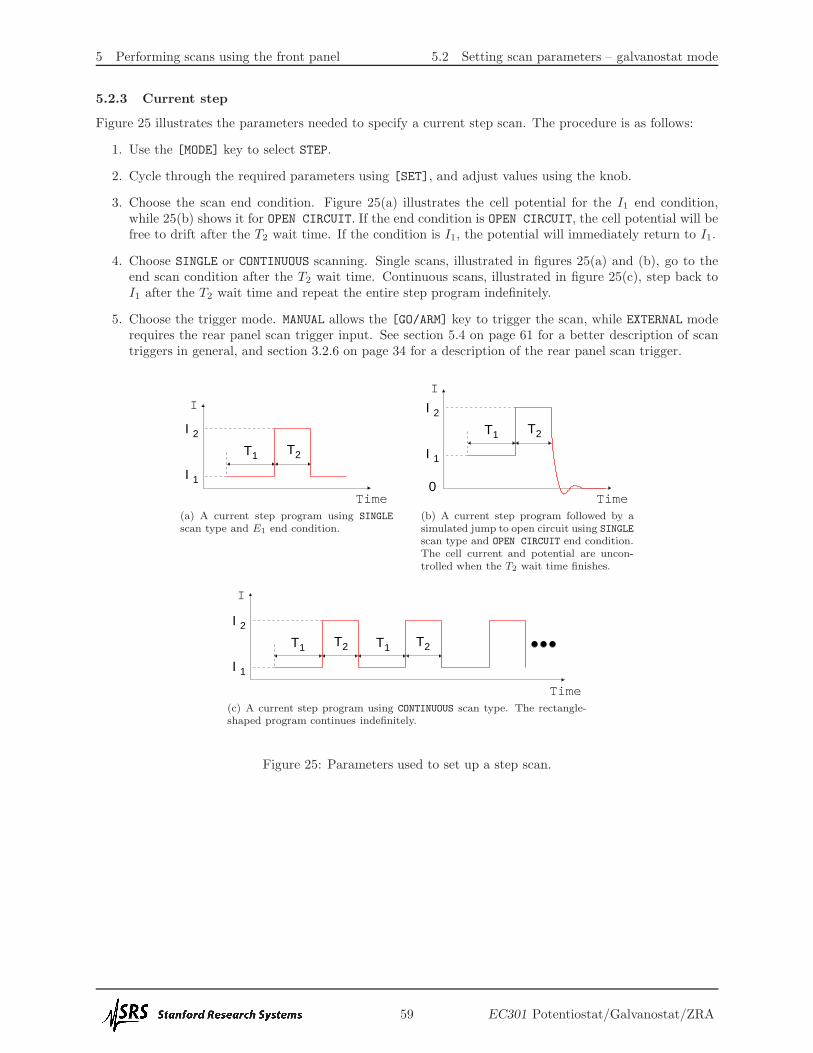
5.3 Basic scan controls
PAUSEGO/ARM
STOPADVANCE
Once a scan is configured, the [GO/ARM], [PAUSE], [ADVANCE], and[STOP] keys control how it will execute.
Pressing the [GO/ARM] key is one way to send a scan triggerdescribed in section 5.4. This will begin a scan in MANUAL triggermode, or arm the instrument in EXTERNAL mode.
The [PAUSE] key freezes the scan wherever it happens to be.Pressing it again will resume the scan.
The [ADVANCE] key increments the scan stage. For example,pressing this during the forward ramp of a CV scan will start thereturn ramp. Pressing this during the return ramp will skip to the
end scan condition.The [STOP] key terminates the scan and releases cell control. This does not simply take the scan to the
scan end condition – control is always released. Use the [ADVANCE] key instead to skip to the end of a scan.
5.4 Triggering scans
A configured scan will start once the EC301 receives a scan trigger. This can come from the front panel[GO/ARM] button, the rear panel scan trigger input, or the remote interface.
5.4.1 Triggering a scan from the front panel
As described in section 3.1.14 on page 29, the front panel [GO/ARM] key will start a scan if the trigger modeis set to MANUAL. Pressing this in the EXTERNAL trigger mode will “arm” the instrument – control will engagebut scanning will wait for the scan trigger input.
The [GO/ARM] key will try to engage cell control to begin a scan in both trigger modes –lighting the [ENABLE] switch. Make sure to allow this by pressing this switch to the “on”position.
5.4.2 Triggering a scan with the scan trigger input
As described in section 3.2.6 on page 34, the rear panel scan trigger input allows fine control over when thescan begins. This can help to synchronize external data acquisition during fast scans.
5.4.3 Triggering a scan from the remote interface
The scan trigger remote commands are described in section 7.3.6 on page 73.
5.5 Setting the end of scan condition
E1 I1
OPEN CIRCUIT
SCANENDS AT
The EC301 can either retain or release control of a cell at the endof a scan. Retaining control may reduce drift in cell characteristicsbetween scans, while releasing control may reduce stress on the cell.Select OPEN CIRCUIT to release control, or E1/I1 to retain controlat the E1 or I1 setting.
61 EC301 Potentiostat/Galvanostat/ZRA

5 Performing scans using the front panel 5.5 Setting the end of scan condition
Only OPEN CIRCUIT is allowed as an end condition for HOLD or TIMED HOLD scan modes.
62 EC301 Potentiostat/Galvanostat/ZRA

6 Using the EC301 with a frequency response analyzer (FRA)
6 Using the EC301 with a frequency response analyzer (FRA)
The EC301 can be used with an FRA to perform electrochemical impedance spectroscopy (EIS) measure-ments. The FRA supplies the stimulus for these measurements via the external input, and measures thecell response via the E and I outputs. Figure 27 shows the EC301 used with the Stanford Research SystemsSR780 for this purpose.
For best results, especially at high frequency, SRS recommends using the rear panel outputs for EISmeasurements.
SR780
BA
Channel 1 Channel 2
AB
Current
Source
Voltage External input
AUTORANGE
E2 / I2E
2T
1T1 / I1E
kΩ
1 Αµ
10
10 mA
1 mA
1 A
100 mA
100 nA
10 nA
1 nA
CURRENT RANGE
VOLTAGE
OUTPUTSLOAD WITH 10
50 Ω
10 HzLOW PASS
FILTER
CURRENT
REJECTIONBIAS
ANALOG OUTPUT
0−10V
SET
ROTATING ELECTRODE
MODE
POTENTIOSTAT
GALVANOSTAT
ZRA
CALIBRATE
MODE
ENABLE
30V/1A MAX COMPLIANCE
CELL
BANDWIDTH LIMIT
100 kHz
1 MHz
10 kHz
1 kHz
100 Hz
10 Hz
CE LIMIT VOLTAGE OVERLOAD CURRENT OVERLOAD
IR COMPENSATION
EC301 POTENTIOSTAT / GALVANOSTAT / ZRA TRACKING
CONFIGUREMEASUREMENT SETUP / CONTROL
EXTERNAL INPUTREMOTE STATUS
ENABLE
INTERRUPT
FEEDBACK
MODE SET
LSV
MODE
RATE
SET
GO/ARM PAUSE
ADVANCE STOPSTOP
STANFORD RESEARCH SYSTEMS
OPEN CIRCUIT
SCAN
ENDS AT
SINGLE
CONTINUOUS
SCAN
TYPE
EXTERNAL
MANUAL
TRIGGER
SRQ
REMOTE MODE
ERROR
EXT TIMEBASE
ACTIVITY
LOCAL
GPIBCV
STEP
HOLD
TIMEDHOLD
GPIB TCP/IP DISPLAY
ENTER
ENABLE
SET LIMIT
LIMITING
V
A
mA
nA
DIRECTCONTROL
ADD TOSCAN
2 V GALVANOSTAT
15 V POTENTIOSTAT
Αµ
100 Αµ
Ω
+
+
Aµ
1I1
50 pF10 k
Figure 27: Using the EC301 with the SR780 for impedance spectroscopy
Using the setup shown in figure 27, the SR780 supplies the stimulus for swept-sine or FFT-based mea-surements via the external input BNC. It then can calculate the complex cell frequency response as
Response =FFT2
FFT1(1)
for FFT-based measurements or as
Response =spectrum2
spectrum1(2)
using the swept-sine mode. The cell impedance Zcell can be calculated from this using
Zcell =spectrum2
Ifs × spectrum1(3)
where Ifs is the current range (10mA, 100µA, etc).
63 EC301 Potentiostat/Galvanostat/ZRA

7 Remote programming
7 Remote programming
The EC301 may be remotely programmed via either the GPIB or ethernet interfaces.When using the ethernet interface, be advised that some “personal firewall” systems will terminate idle
connections.
7.1 Command syntax
Communication with the EC301 is done with ASCII characters. Commands may be in either UPPER orlower case and may contain any number of embedded space characters. For example, the commands
ECMODE 1
ECMODE 1
ecmode 1
will all put the instrument in galvanostat mode.Multiple commands may be sent on one command line by separating them with semicolons (;). The
individually-sent commands
ecmode 1
clbwth 4
irange 1
can be sent simultaneously with
ecmode 1;clbwth 4;irange 1
following which the EC301 will buffer and then execute the command string from left to right.
7.2 Argument formats
Table 3 summarizes the number formats expected for each argument designator.
Argument designators Format Good examples Unrecognized
i,j,k integer -1200,0,1,5,+6-1.2e3,0x5
x,y,z real number -1.34,0.0,3.14159
Table 3: Number formats expected for each argument designator.
Numbers written in scientific notation will not be recognized as allowed arguments.
64 EC301 Potentiostat/Galvanostat/ZRA

7 Remote programming 7.3 Detailed command list
7.3 Detailed command list
7.3.1 Firmware and hardware revisions
fpgarv?Name: fpgarv? – Query the FPGA revision number.Description: The instrument’s FPGA revision number is important for firmwareupgrades.
7.3.2 Program E/I setup (with external input)
setvol(?)i
Name: setvol(?) – Set or query DC bias voltage.Description: This command provides an easy way to control a DC voltage with-out setting up a scan.
Parameter Units Range
i mV −15000,−14999,−14998, · · · ,+15000
For example, the sequence
ecmode 0
ceenab 1
setvol 1000
setvol?
1000
will set up a program voltage of 1V in potentiostat mode. The setvol? querycommand will return a value in the same format as the setting. This commandis not allowed in galvanostat mode, zra mode, or if the unit is in direct controlmode.
65 EC301 Potentiostat/Galvanostat/ZRA
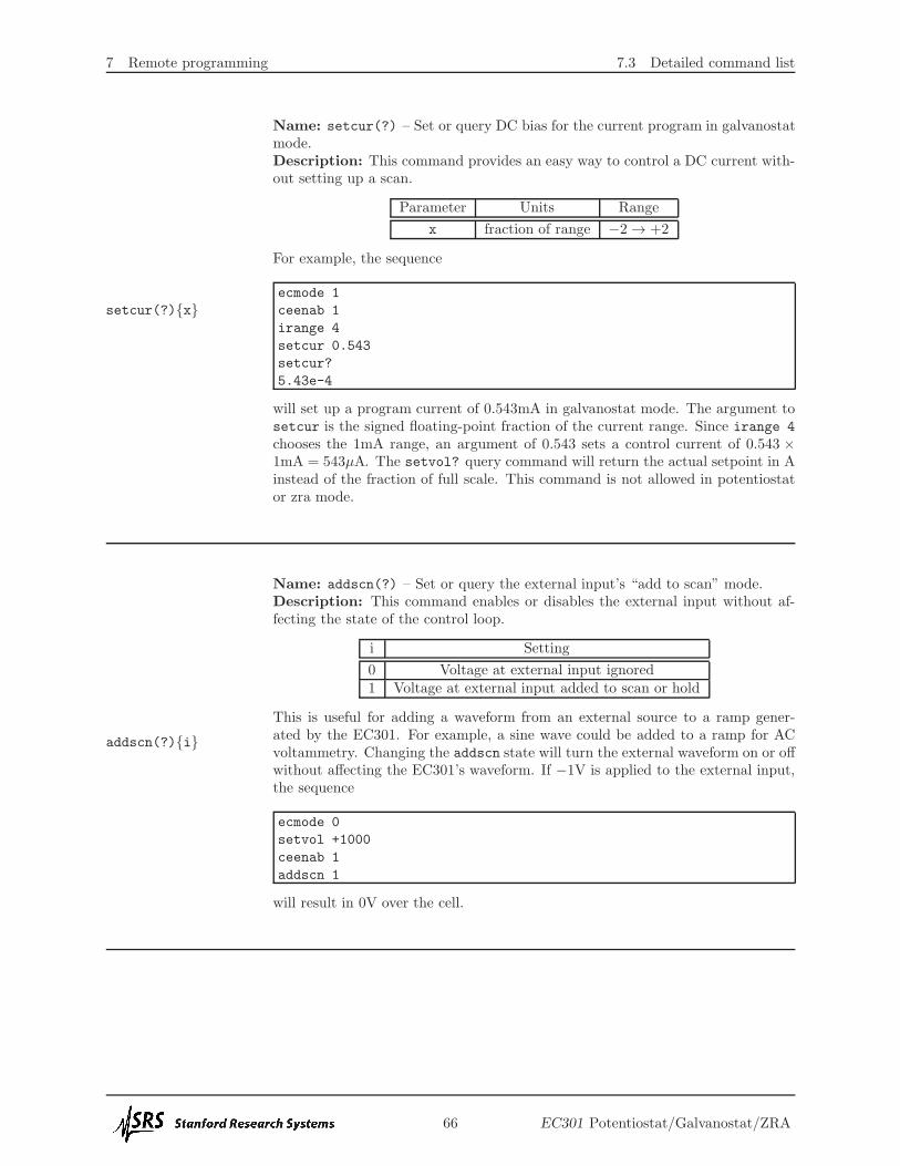
7 Remote programming 7.3 Detailed command list
setcur(?)x
Name: setcur(?) – Set or query DC bias for the current program in galvanostatmode.Description: This command provides an easy way to control a DC current with-out setting up a scan.
Parameter Units Range
x fraction of range −2→ +2
For example, the sequence
ecmode 1
ceenab 1
irange 4
setcur 0.543
setcur?
5.43e-4
will set up a program current of 0.543mA in galvanostat mode. The argument tosetcur is the signed floating-point fraction of the current range. Since irange 4
chooses the 1mA range, an argument of 0.543 sets a control current of 0.543 ×1mA = 543µA. The setvol? query command will return the actual setpoint in Ainstead of the fraction of full scale. This command is not allowed in potentiostator zra mode.
addscn(?)i
Name: addscn(?) – Set or query the external input’s “add to scan” mode.Description: This command enables or disables the external input without af-fecting the state of the control loop.
i Setting
0 Voltage at external input ignored1 Voltage at external input added to scan or hold
This is useful for adding a waveform from an external source to a ramp gener-ated by the EC301. For example, a sine wave could be added to a ramp for ACvoltammetry. Changing the addscn state will turn the external waveform on or offwithout affecting the EC301’s waveform. If −1V is applied to the external input,the sequence
ecmode 0
setvol +1000
ceenab 1
addscn 1
will result in 0V over the cell.
66 EC301 Potentiostat/Galvanostat/ZRA

7 Remote programming 7.3 Detailed command list
dcntrl(?)i
Name: dcntrl(?) – Set or query the external input’s “direct control” mode.Description: This command enables or disables the external input while engagingand disengaging cell control.
i Setting
0 Voltage at external input ignored1 Voltage at external input applied to cell
This is useful when you have an external source for your entire stimulus and youdon’t want to use the internal sources. Sending dcntrl 1 works like pushing[DIRECT CONTROL] on the front panel – the control loop will close with thecontrol voltage taken from the external input BNC. However, sending dcntrl 0
will only open the control loop if the external input has been put in charge withdcntrl 1 – not if an internally-generated scan or hold is running.
This command will generate an error if an internally-generatedscan or hold is already running. Make sure all control has beenreleased before sending dcntrl 1.
progrm?
Name: progrm? – Read the program E/I voltage.Description: This command queries the total voltage program input to the con-trol loop.
Parameter Units Range
x V −15.000→ +15.000
The program input is the sum of voltages from the external input BNC and frominternal sources. This command is useful during current interrupt IR compensa-tion, as the values returned should represent the cell voltage with any IR dropremoved. Returned values are formatted as floating-point volts. For example, thesequence
ecmode 0
setvol 123
progrm?
+0.123
calls for +123mV to be applied to the cell in potentiostat mode. If there is noexternal input voltage, the return value of progrm? will be +0.123.
67 EC301 Potentiostat/Galvanostat/ZRA

7 Remote programming 7.3 Detailed command list
7.3.3 Control loop commands
ecmode(?)i
Name: ecmode(?) – Set or query the control loop mode.Description: The control loop can take its feedback from one of three sources,resulting in the three modes described below.
i Mode
0 Potentiostat1 Galvanostat2 Zero-resistance ammeter (ZRA)
clbwth(?)i
Name: clbwth(?) – Set or query the control bandwidth.Description: Set or query the control loop bandwidth.
i Control loop bandwidth
0 1 MHz1 100 kHz2 10 kHz3 1 kHz4 100 Hz5 10 Hz
celimt(?)i
Name: celimt(?) – Enables or disables CE voltage limiting mode.Description: Sending this command is identical to using the front panel[ENABLE] key in the CE LIMIT group. See the description in section 3.1.3 onpage 22 for more information.
i Setting
0 Disable – full ±30V compliance1 Enable – CE voltage limit set with front panel or celimv command.
celimv(?)i
Name: celimv(?) – Set the CE voltage clamp limits.Description: The CE limits are symmetric about SIGNAL GROUND. For example,the command celimv 1000 will limit the CE voltage to ±1V of SIGNAL GROUND.
Parameter Units Range
x mV 500, 501, 502, · · · , 30000
68 EC301 Potentiostat/Galvanostat/ZRA

7 Remote programming 7.3 Detailed command list
limitg?
Name: limitg? – Query if the CE Limit is active.
Description: limitg? returns 1 if the CE limit is active, 0 if the limit is inactive.Use the celimt command to enable or disable the CE limiting.
69 EC301 Potentiostat/Galvanostat/ZRA

7 Remote programming 7.3 Detailed command list
7.3.4 Cell switch
ceenab(?)i
Name: ceenab(?) – Set or query the CE switch position.Description: Enable or disable the cell. The red “enable” switch on the frontpanel will illuminate if the cell is enabled and the switch is pushed in.
i Cell connection
0 Disabled1 Enabled
cellon?i
Name: cellon? – Query the cell connection.Description: This query-only command returns the state of the cell connection.As shown in figure 1 on page 18, this connection is made only if both the currentinterrupt cell switch and the front panel safety switch are closed. Since the safetyswitch lights up only when both of these are closed, this query tells you whetheror not this light is on.
i Cell connection
0Disconnected – Either the current interrupt cell switch orthe front panel safty switch is open (safety switch redlight is off).
1Connected – Both the current interrupt cell switch andthe front panel safety switch are closed (safety switch redlight is on).
70 EC301 Potentiostat/Galvanostat/ZRA

7 Remote programming 7.3 Detailed command list
7.3.5 IR compensation
irenab(?)i
Name: irenab(?) – Enable or disable IR compensation.Description: Enable or disable either mode of IR compensation. This corre-sponds to pushing the front panel [ENABLE] key described in section 3.1.12 onpage 27.
i Setting
0 Disable IR compensation1 Enable IR compensation
irtype(?)i
Name: irtype(?) – Set or query the IR compensation mode.Description: Set or query the IR compensation mode. This corresponds topushing the front panel [MODE] key described in section 3.1.12 on page 27.
i Setting
0 Current interrupt1 Positive feedback
pfback(?)x
Name: pfback(?) – Set the positive feedback amount.Description: No description.
Parameter Units Range
x none 0 → fff
ciopen(?)i
Name: ciopen(?) – Set or query the CE switch open time for current interrupt.Description: This command sets or queries the “interruption” time for currentinterrupt IR compensation. The resolution is 100µs. This corresponds to the topendelay shown in figure 6 on page 27.
Parameter Units Range
i µs 100, 200, 300, · · · , 1× 10⁶(1s)
The interruption time must be shorter than the time betweeninterrupts. Be sure to set a valid value for ciperd after settingciopen.
71 EC301 Potentiostat/Galvanostat/ZRA

7 Remote programming 7.3 Detailed command list
ciperd(?)i
Name: ciperd(?) – Set or query the interruption frequency for current interrupt.Description: This command sets or queries the tp period described in figure 6on page 27. This is the time between interrupt cycles, set with 1ms resolution.
Parameter Units Range
i ms 1, 2, 3, · · · , 10000
The time between interrupt cycles (tp) must be longer than theinterruption time (topen). Be sure to set a valid value for ciopen(described on the preceding page) after setting ciperd (describedon the current page).
cicorr(?)i
Name: cicorr(?) – Set or query the correction percentage used for currentinterrupt IR compensation.Description: As described in section 3.1.12 on page 27, a fraction of ∆Vir isadded to the program voltage after current interruptions. Sending cicorr 0 willmake ∆Vb = 0, and sending cicorr 100 will make ∆Vb = ∆Vir.
Parameter Units Range
i % 0, 1, 2, · · · , 200
cidlay(?)ij
Name: cidlay(?) – Set or query the voltage sampling times used during currentinterrupt IR compensation.Description: This command sets the tdo and tdc sample delays described in figure6 on page 27. Both sample delays are entered in integer µs.
i Delay Units j
0 tdo (open delay)µs 0,1,2,· · · ,1× 106(1s)
1 tdc (closed delay)
72 EC301 Potentiostat/Galvanostat/ZRA

7 Remote programming 7.3 Detailed command list
7.3.6 Scan trigger commands
trgarm(?)i
Name: trgarm(?) – Set or query the scan trigger arm condition.Description: The instrument must be armed before a scan can be started withan external trigger. The armed instrument will wait for a trigger edge beforescanning. This command will set or query this waiting (armed) state. See section3.1.14 on page 29 for more information about the external trigger setting. Seesection 3.2.6 on page 34 for more information about the rear panel scan triggerinput.
i Mode
0 Unarmed1 Armed – waiting for external scan trigger
scntrg?
Name: scntrg(?) – Query the scan trigger state (are we scanning?).Description: This command will tell you if the instrument is running an auto-matic scan.
Return value Mode
0 Not triggered1 Triggered (scanning)
stsync(?)i
Name: stsync(?) – Set or query whether software triggered scans are synchro-nized with the power line cycle.Description: If the argument to STSYNC is 1, a remote command software-triggered scan (i.e. not triggered from the front panel) will not begin until thepower line cycle measuring circuit detects a zero crossing. This allows the user tosynchronize a fast cyclic voltammogram to occur at the same point in a power linecycle each time such a trigger is issued. The default is not to gate with the powerline cycle, and begin the scan immediately.
i Mode
0 No power line synchronization1 Software triggered scans aligned to power line cycle
73 EC301 Potentiostat/Galvanostat/ZRA

7 Remote programming 7.3 Detailed command list
7.3.7 Rotating working electrode commands
rotate(?)x
Name: rotate(?) – Set or query the rotator output voltage.Description: No description.
Parameter Units Range
x mV 0 → 10000
74 EC301 Potentiostat/Galvanostat/ZRA
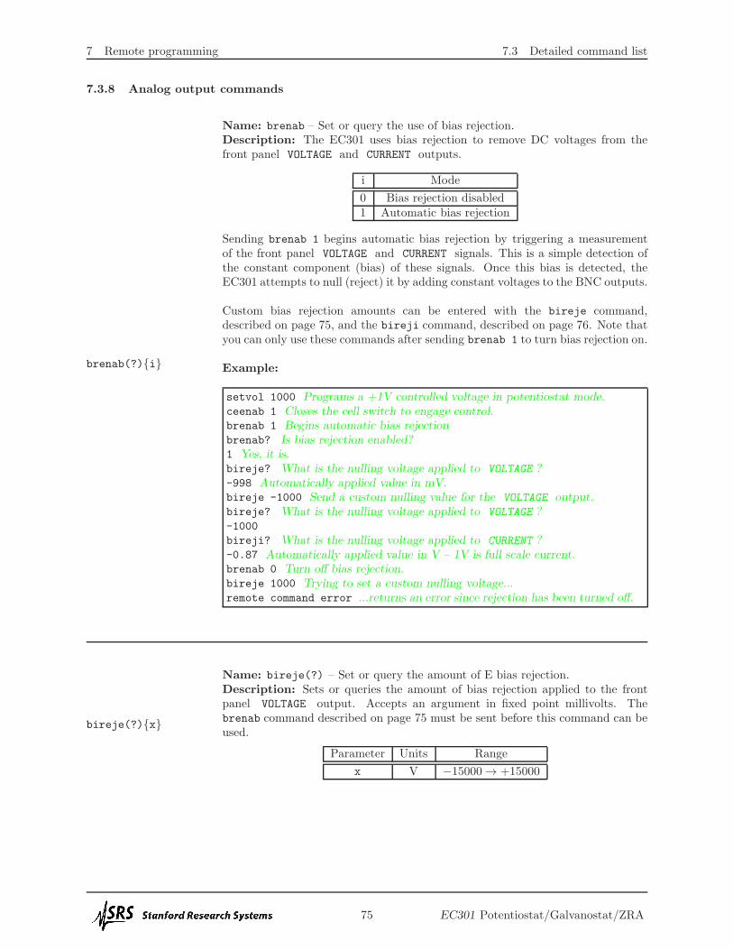
7 Remote programming 7.3 Detailed command list
7.3.8 Analog output commands
brenab(?)i
Name: brenab – Set or query the use of bias rejection.Description: The EC301 uses bias rejection to remove DC voltages from thefront panel VOLTAGE and CURRENT outputs.
i Mode
0 Bias rejection disabled1 Automatic bias rejection
Sending brenab 1 begins automatic bias rejection by triggering a measurementof the front panel VOLTAGE and CURRENT signals. This is a simple detection ofthe constant component (bias) of these signals. Once this bias is detected, theEC301 attempts to null (reject) it by adding constant voltages to the BNC outputs.
Custom bias rejection amounts can be entered with the bireje command,described on page 75, and the bireji command, described on page 76. Note thatyou can only use these commands after sending brenab 1 to turn bias rejection on.
Example:
setvol 1000 Programs a +1V controlled voltage in potentiostat mode.ceenab 1 Closes the cell switch to engage control.brenab 1 Begins automatic bias rejectionbrenab? Is bias rejection enabled?1 Yes, it is.bireje? What is the nulling voltage applied to VOLTAGE ?-998 Automatically applied value in mV.bireje -1000 Send a custom nulling value for the VOLTAGE output.bireje? What is the nulling voltage applied to VOLTAGE ?-1000
bireji? What is the nulling voltage applied to CURRENT ?-0.87 Automatically applied value in V – 1V is full scale current.brenab 0 Turn off bias rejection.bireje 1000 Trying to set a custom nulling voltage...remote command error ...returns an error since rejection has been turned off.
bireje(?)x
Name: bireje(?) – Set or query the amount of E bias rejection.Description: Sets or queries the amount of bias rejection applied to the frontpanel VOLTAGE output. Accepts an argument in fixed point millivolts. Thebrenab command described on page 75 must be sent before this command can beused.
Parameter Units Range
x V −15000→ +15000
75 EC301 Potentiostat/Galvanostat/ZRA

7 Remote programming 7.3 Detailed command list
bireji(?)x
Name: bireji(?) – Set or query the amount of I bias rejection.
Description: Sets or queries the amount of bias rejection applied to the frontpanel CURRENT output. The brenab command described on page 75 must be sentbefore this command can be used. The argument is in floating point, and indicateswhat fraction of full scale current will be rejected.
Parameter Units Range
x fraction of full scale −2.000→ +2.000
lpfile(?)i
Name: lpfile(?) – Set or query the front panel E low pass filter status.Description: No description.
i Setting
0 No filter1 10Hz lowpass
lpfili(?)i
Name: lpfili(?) – Set or query the front panel I low pass filter status.Description: No description.
i Setting
0 No filter1 10Hz lowpass
76 EC301 Potentiostat/Galvanostat/ZRA

7 Remote programming 7.3 Detailed command list
7.3.9 Voltage (E) measurement setup
eadcrg(?)i
Name: eadcrg(?) – Set or query the full-scale range of the internal E measure-ment.Description: The instrument defaults to a ±15V measurement range. This canbe reduced to increase measurement resolution.
i Setting
0 ±2 V1 ±5 V2 ±15 V
eadcfl(?)i
Name: eadcfl(?) – Set or query the low pass filter in front of the E ADC.Description: No description.
i Setting
0 No filter1 10Hz lowpass2 10kHz lowpass (anti-alias)
77 EC301 Potentiostat/Galvanostat/ZRA

7 Remote programming 7.3 Detailed command list
7.3.10 Current (I) measurement setup
irange(?)i
Name: irange(?) – Set or query the current range.Description: No description.
i Current range
1 1A2 100mA3 10mA4 1mA5 100µA6 10µA7 1µA8 100nA9 10nA10 1nA
You cannot do irange if you are autoranging.
iadcfl(?)i
Name: iadcfl(?) – Set or query the low pass filter in front of the I ADC.Description: No description.
i Setting
0 10Hz lowpass1 No filter2 10kHz lowpass (anti-alias)
78 EC301 Potentiostat/Galvanostat/ZRA

7 Remote programming 7.3 Detailed command list
irnaut(?)i
Name: irnaut(?) – Set or query the I autoranging mode.Description: The current measurement circuit can automatically change rangeswhen the measured current is at the extreme end of a range.
i Autoranging
0 Off1 On
Autoranging of the I/V converter is disallowed if any of theseconditions are true:
• Galvanostat mode is in use.
• Positive feedback IR compensation is in use.
• Bias rejection is in use.
79 EC301 Potentiostat/Galvanostat/ZRA

7 Remote programming 7.3 Detailed command list
7.3.11 Reading single measurement results
vlevel?
Name: vlevel? – return an E measurement.Description: This query only command takes no arguments and returns a floatingpoint number in volts. For example, if (VWE SENSE −VRE) happens to be -1.543V,the sequence
vlevel?
-1.543
will return that value.
ilevel?
Name: ilevel? – return an I measurement.Description: This query only command takes no arguments and returns a floatingpoint number in amps. For example, if IWE happens to be -1.543mA, the sequence
ilevel?
-1.543e-3
will return that value.
getaux?i
Name: getaux? – Get voltages from the rear panel auxiliary input BNCs.Description: This query-only command returns voltage measurements made withthe rear panel auxiliary input BNCs described on page 38.
i Voltage returned
1 Auxiliary input 1
2 Auxiliary input 2
3 Auxiliary input 3
4 Comma delimited values from all three channels
Example:
getaux? 1 Query the voltage at auxiliary input BNC 11.723993 Volts
80 EC301 Potentiostat/Galvanostat/ZRA

7 Remote programming 7.3 Detailed command list
avgexp(?)i
Name: avgexp(?) – Set or query the running average length.Description: Sets or queries the number of data points averaged to make ameasurement result. The averaged number is 2i.
Parameter Range
i 0,1,2,· · · ,8
For example, the sequence
avgexp 4
will make every measurement returned over the remote interface an average of24 = 16 internal measurements.
Sending avgexp clears the instruments’s existing averaged datamemory. New measurement results won’t be accurate until thememory is allowed to refil, which takes ∼30ms. Please wait atleast 30ms after sending avgexp to ensure that measurement re-sults are accurate.
81 EC301 Potentiostat/Galvanostat/ZRA

7 Remote programming 7.3 Detailed command list
7.3.12 Streaming data
getbdai
Name: getbda – Start or stop binary data streaming.Description: This command is intended for users writing their own data acqui-sition software. See figure 28 on page 83 for an overview of data packets used forstreaming.
i Action
0 Stop streaming data1 Start streaming data
polbda?
Name: polbda? – Get a single packet of binary data.Description: This command is intended for users writing their own data acqui-sition software. See figure 28 on page 83 for an overview of data packets used forstreaming. While the getbda? command (page 82) tells the instrument to startstreaming an indefinite number of data packets, polbda asks for just one. This isuseful for “polling” data acquisition, in which the host PC sends polbda? overand over again to collect data.
getbdp?iName: getbdp? – Query the binary data streaming protocol.Description: This query-only command is used by host software to interpretstreaming binary data. This manual documents protocol 2.
Binary data streams in from the EC301 least significant bit (LSB) first, and that maycause some confusion with binary → hexadecimal converters that operate byte-by-byte.For example, if the EC301 wants to send 0xdeadbeef, it will send
MSB, arrives last → 11011110101011011011111011101111← LSB, arrives first
...and the byte-by-byte hexadecimal conversion will make this 0xefbeadde. You have toreverse the byte order inside each streamed word to recover the correct value.
82 EC301 Potentiostat/Galvanostat/ZRA

7 Remote programming 7.3 Detailed command list
Synchronous ADC
Header
4 bytes
4 bytes
4 bytes
4 bytes
Seconddata
frame
Lastdata
frame
Firstdata
frame
2 bytes
Reserved
Payload length
Packet counter
I data
E data
Temperature
Auxiliary ADC 1
Auxiliary ADC 2
4 bytes
4 bytes
4 bytes
4 bytes
Footer
"Fast" state bitfields
Auxiliary ADC 3
(0x0d0a = "\r\n")Header terminator:
E/I overload record
16 bytes1 byte
1 byte
Header marker: (0x1f)
Header length: (0x10)
4 bytes
4 bytes
1 byte
1 byte
2 bytes
Reserved
Header checksum
1 byte
6 bytesReserved
Full checksum 1 byte
24 bytes
Figure 28: Basic construction of the data packet used for streaming data. The four bytes of “fast” instrumentstate in each data frame are described in table 4 on page 84. The E/I overload record byte in the footer isdescribed in table 5 on page 85.
83 EC301 Potentiostat/Galvanostat/ZRA

7 Remote programming 7.3 Detailed command list
Bit Quantity Values
0 Cell switch position0 On (closed)1 Off (open)
1 Internal use Internal use
2 Power line synchronization toggle Toggle after each zero crossing
3 Compliance limiting status0 Not limiting1 Limiting
4:7 Current (I) range
1 1A2 100mA3 10mA4 1mA5 100µA6 10µA7 1µA8 100nA9 10nA10 1nA
8:10 Voltage (E) range3 2V5 5V6 15V
11 Ramp waveform generator status0 Idle1 Running
12 Ramp waveform synchronization toggle Toggle after ramps begin and repeat
13:14 Internal use Internal use
15:18 Data averaging window width N 2N points wide
19 Pulse waveform generator status0 Idle1 Running
20 Pulse waveform edge toggle Toggle after each edge
21 Pulse waveform synchronization toggleToggle after pulse waveforms begin
and repeat
22 Arbitrary waveform generator status0 Idle1 Running
23 Arbitrary waveform synchronization toggleToggle after arbitrary waveforms begin
and repeat
24:31 Internal use Internal use
Table 4: “Fast” instrument state bitfields built into each data frame.
84 EC301 Potentiostat/Galvanostat/ZRA

7 Remote programming 7.3 Detailed command list
Bit Quantity Values
0:1 Reserved Reserved
2 E overload record
0No overloads detected duringthe last packet.
1One or more overloads detectedduring the last packet.
3 I overload record
0No overloads detected duringthe last packet.
1One or more overloads detectedduring the last packet.
4:7 Reserved Reserved
Table 5: Bit positions in the E/I overload record byte.
85 EC301 Potentiostat/Galvanostat/ZRA

7 Remote programming 7.3 Detailed command list
7.3.13 Remote interface commands
*IDN?
Name: *IDN? – return the EC301’s device identification string.Description: This query only command takes no arguments and returns thedevice identification string.
*RST
Name: *RST – Reset the EC301 to its default configuration.Description: This command sets all modes and settings to their default config-urations and values.
*TST?Name: *TST? – return the Power-on Self Test (POST) results.Description: This command has no description.
*OPC(?)
Name: *OPC(?) – Operation complete.Description: This command is implemented for compatibility with the IEEE-488standard. The original intent was for *OPC? queries to indicate when a longprocess was complete. The EC301 executes commands as it receives them though,and so the *OPC? query will be always be processed after the long process finishes.These queries will thus always return 1, indicating that all previous operationsare complete.
This command can still be used to indicate when the instrument is ready to processnew commands. In this example,
*OPC?
Long process finishes...
1
waiting for the 1 to be returned would indicate completion of all commands. Thenon-query version of the command simply sets the *OPC bit in the Standard EventStatus Register when the long process finishes. See the *ESR documentation onpage 90 for a description of this register.
*WAI
Name: *WAI – Wait to continue.Description: This command is implemented for compatibility with the IEEE-488 standard. The original intent was for *WAI to prevent the instrument fromexecuting commands until it completed all pending operations.
86 EC301 Potentiostat/Galvanostat/ZRA

7 Remote programming 7.3 Detailed command list
verbmd(?)i
Name: verbmd(?) – Set or query the instrument’s verbosity.Description: This command sets or queries the instrument’s verbosity using themapping below. In terse mode, the instrument will issue no unsolicited output –such as error messages. This mode suits automated equipment that can not handleunexpected inputs. In verbose mode, the instrument will issue warning and errormessages as needed.
i Mode
0 Terse mode1 Verbose mode
lockfp(?)i
Name: lockfp(?) – Set or query front panel lockout.Description: The front panel keypad can be disabled to prevent inadvertentadjustments.
i Mode
0 Front panel unlocked – normal operation1 Front panel disabled
All buttons except [LOCAL] will be disabled after sending lockfp 1. Pressing[LOCAL] will unlock the front panel and reset lockfp to 0.
ifcclr
Name: ifcclr – Reset the remote interface.Description: This command clears the remote interface’s transmit and receivequeues. If the instrument’s reply to a query isn’t read before another query isissued, an error occurrs and new reads are forbidden. Sending ifcclr when thishappens will clear this condition, allowing new queries to be sent and their replysto be read.
The REF bit in the instrument status register described on page 92 is set whenmultiple queries are sent without a read. Sending ifcclr will not clear this bit –it should be cleared with a normal INSR? query.
macadr?Name: macadr? – return the EC301’s Media Access Control (MAC) address.Description: This query only command takes no arguments and returns theMAC address.
87 EC301 Potentiostat/Galvanostat/ZRA

7 Remote programming 7.3 Detailed command list
vfdmsgistring
Name: vfdmsg – Display a string on the character display.Description: This set-only command prints the input string argument to eitherthe first or second line of the front panel vacuum fluorescent character display.The string must be less than 24 characters long, and may not contain any spaces,tabs, or other whitespace characters.
i Display line
0 Top line1 Bottom line
For example, the command
vfdmsg 0 string to display
will print STRING TO DISPLAY on the top line of the character display.
nulcmd(?)i
Name: nulcmd – Do absolutely nothing.Description: This command is useful for testing the remote interface withoutdoing any harm. Sending the nulcmd? query will always return 0.
Example:
nulcmd? Does nothing but write 0 to the transmit queue.0
88 EC301 Potentiostat/Galvanostat/ZRA

7 Remote programming 7.3 Detailed command list
7.3.14 Timebase commands
exttmb?i
Name: exttmb – Query the timebase.Description: This query-only command returns the state of the sampling time-base.
i Timebase setting
0 Internally generated (no external timebase present)
1Externally generated (external timebase automaticallyselected when present)
2Internally generated (external timebase present, but disabledvia the autotb command described on this page).
autotbi
Name: autotb – Turn automatic timebase selection on or off.Description: This set-only command turns automatic timebase selection on oroff. Use the exttmb? query described above to query the timebase selection state.
i Setting
0Manual mode – timebase generated internally even though anexternal timebase is present.
1Automatic mode – timebase generated internally by default,but accepted from external source if present.
89 EC301 Potentiostat/Galvanostat/ZRA

7 Remote programming 7.3 Detailed command list
7.3.15 Status reporting commands
*ESR?i
Name: *ESR? – Query the Standard Event Status register.Description: This command returns values from the Standard Event Status reg-ister. Sending *ESR? will return the entire register value in decimal format, whilesending *ESR? i will only return bit i. Reading the register will also clear it.Sending *ESR? will clear the entire register, while sending *ESR? i will only clearbit i. Table 6 below lists the conditions corresponding to the register bits. Use the*ESE register described on the following page to enable these bits to set a bit inthe Status Byte. See figure 29 on page 99 for an overview of status bit promotion.
Bit Name Set when...
0 OPC The *OPC command has completed.
1 Unused
2 QYE Query error – data has been lost instead of transmitted.
3 DDEDevice specific error – an error was encountered whileexecuting a remote command.
4 EXEExecution error – a remote command could not be executeddue to an argument or state problem.
5 CME Command error – an invalid remote command was received.
6 URQUser request – front panel activity was attempted regardlessof local/remote status.
7 PON The unit has turned on.
Table 6: The Standard Event Status register bits.
The Standard Event Status register is defined by the IEEE-488.2 (1987) standard,and is used primarily to report errors in commands received over the remoteinterface. These bits remain set until read, cleared by the *CLS command, oruntil the unit is turned on with *PSC enabled.
Example:
*ESR? Returns the Standard Event Status register value (0→255)*ESR? 5 Returns 0 if bit 5 (CME) is cleared, or 1 if it is set.
90 EC301 Potentiostat/Galvanostat/ZRA

7 Remote programming 7.3 Detailed command list
*ESE(?)i,j
Name: *ESE(?) – set or query bits in the Standard Event Enable register.Description: The *ESE i command sets the Standard Event Enable register tothe decimal value i (0 → 255). The *ESE i,j command sets bit i (0 → 7) to j
(0 or 1). As shown in figure 29, bits enabled in the *ESR register via the *ESEregister set the ESB bit in the status byte.
The *ESE? query returns the value (0 → 255) of the Standard Event EnableRegister. The *ESE? i command queries the value (0 or 1) of bit i (0→ 7).
When the instrument sets a bit in the Standard Event Status Register (*ESR,described on the previous page), and the corresponding bit is set in the StandardEvent Enable Register (this one) by the user, bit 5 (ESB) of the Status Byte(*STB, described on page 96) is set. This causes a SRQ if bit 5 in the StatusByte is set.
Example:
*ESE? Returns the register value in decimal format*ESE? 2 Returns 0 if bit 2 is cleared, or 1 if it is set*ESE 48 Sets the register value to 48 (bits 4 and 5 set)*ESE 7,0 Clears bit 7
91 EC301 Potentiostat/Galvanostat/ZRA

7 Remote programming 7.3 Detailed command list
INSR?i
Name: INSR? – Query the Instrument Status Register.Description: This command returns values from the Instrument Status Register.Sending INSR? will return the entire register value in decimal format, while sendingINSR? i will only return bit i. Reading the register will also clear it. SendingISNR? will clear the entire register, while sending INSR? i will only clear bit i.Table 7 lists the conditions corresponding to the register bits. See figure 29 onpage 99 to see an overview of all status registers.
Bit Name Set when...
0 STF Selftest Failure – the selftest has failed.
1 KPEKeypress Event – a key was pressed on the front panel inlocal mode.
2 KROKnob Rotation – a parameter was changed by rotating theknob in local mode.
3 RES Remote Set – a remote set command (not a query) was issued
4 CRCCurrent Range Change – there was a change in the current(I) range.
5-11 Internal use.
12 ETAExternal Timebase Acquired – achieved lock to 10MHztimebase.
13 ETL External Timebase Lost – lost lock to 10MHz timebase.
14 ERR An error has been posted that can be queried with errlst?.
15 REFQuery Refused - a previous query has not been completelyread. Perform read or send ifcclr
Table 7: The Instrument Status register bits.
Example:
INSR? Returns the Instrument Status register value (0→65535)INSR? 4 Returns 0 if bit 4 (CRC) is cleared, or 1 if it is set.
92 EC301 Potentiostat/Galvanostat/ZRA

7 Remote programming 7.3 Detailed command list
INSE(?)i,j
Name: INSE(?) – set or query bits in the Instrument Status Enable Register.Description: The INSE i command sets the Instrument Status Enable registerto the decimal value i (0→ 65535). The INSE i,j command sets bit i (0→ 15)to j (0 or 1). As shown in figure 29 on page 99, bits enabled in the INSR register(defined on the preceding page) via the INSE register (this one) set the INSW bitin the status byte.
The INSE? query returns the value of the Instrument Status Enable register. TheINSE? i command queries only bit i.
When the instrument sets a bit in the Instrument Status Register, and thecorresponding bit is set in the Instrument Status Enable register by the user, bit1 (INSW) of the Status Byte is set. This causes a SRQ if bit 0 in the Status ByteEnable register is set.
Example:
INSE? Returns the register value in decimal formatINSE? 2 Returns 0 if bit 2 is cleared, or 1 if it is setINSE 16 Sets the register value to 16 (bit 4 set)INSE 4,0 Clears bit 4
93 EC301 Potentiostat/Galvanostat/ZRA

7 Remote programming 7.3 Detailed command list
MESR?i
Name: MESR? – Query the Measurement Status register.Description: This command returns values from the Measurement Status regis-ter. Sending MESR? will return the entire register value in decimal format, whilesending MESR? i will only return bit i. Reading the register will also clear it.Sending MESR? will clear the entire register, while sending MESR? i will only clearbit i. Table 8 lists the conditions corresponding to the register bits.
Bit Name Set when...
0 CELCE limit – The CE voltage limit (either ±30V or theuser-defined limit) was reached.
1 EOL E overload – the E measurement exceeded ±15V.
2 IOLI overload – the I measurement exceeded 200% of a range or1A.
3 AO1Auxiliary ADC channel 1 overload – the BNC input exceeded±10V.
4 A02Auxiliary ADC channel 2 overload – the BNC input exceeded±10V.
5 A03Auxiliary ADC channel 3 overload – the BNC input exceeded±10V.
6 NRH No remote amplifier (EC19) detected
7 CIL CE limit – The CE current limit (±1A) was reached.
Table 8: The Measurement Status register bits.
Example:
MESR? Returns the Instrument Status register value (0→65535)MESR? 4 Returns 0 if bit 4 (CRC) is cleared, or 1 if it is set.
94 EC301 Potentiostat/Galvanostat/ZRA

7 Remote programming 7.3 Detailed command list
MESE(?)i,j
Name: MESE(?) – set or query bits in the Measurement Status Enable Register.Description: The MESE i command sets the Measurement Status Enable registerto the decimal value i (0→ 65535). The MESE i,j command sets bit i (0→ 15)to j (0 or 1). As shown in figure 29 on page 99, bits enabled in the MESR register(defined on the preceding page) via the MESE register (this one) set the MESWbit in the status byte.
The MESE? query returns the value of the Measurement Status Enable Register.The MESE? i command queries only bit i.
When the instrument sets a bit in the Measurement Status Register, and thecorresponding bit is set in the Measurement Status Enable register by the user,bit 1 (MESW) of the Status Byte is set. This causes a SRQ if bit 1 in the StatusByte Enable register is set.
Example:
MESE? Returns the register value in decimal formatMESE? 2 Returns 0 if bit 2 is cleared, or 1 if it is setMESE 48 Sets the register value to 48 (bits 4 and 5 set)MESE 7,0 Clears bit 7
95 EC301 Potentiostat/Galvanostat/ZRA

7 Remote programming 7.3 Detailed command list
*STB?i
Name: *STB? – Query Status Byte values.Description: This command returns values from the Status Byte register. Send-ing *STB? will return the entire register value in decimal format, while sending*STB? i will only return bit i. Reading this register will not clear it – it mustbe cleared by reading the registers that feed it. See figure 29 on page 99 for adescription of how status bit values are promoted to this register. Table 9 lists theconditions corresponding to the register bits.
Bit Name Set when...
0 INSWAn unmasked bit in the Instrument Status Register(described on page 92) has been set.
1 MESWAn unmasked bit in the Measurement Status Register(described on page 94) has been set.
2 Not used.
3 Not used.
4 MAV There is a message available in the GPIB queue.
5 ESBAn unmasked bit in the Standard Event Status Register(described on page 90) has been set.
6 SRQService request. See the *SRE command described on thenext page for more information.
7 IFC Set when the remote interface’s receive queue is full.
Table 9: The Status Byte Register bits.
96 EC301 Potentiostat/Galvanostat/ZRA

7 Remote programming 7.3 Detailed command list
*SRE(?)i,j
Name: *SRE(?) – set or query bits in the Status Byte Enable register.Description: The *SRE i command sets the Status Byte Enable register to thedecimal value i (0→ 255). The *SRE i,j command sets bit i (0→ 7) to j (0 or1). As shown in figure 29 on page 99, bits enabled in the *STB register via the*SRE register set the SRQ bit.
The *SRE? query returns the value (0 → 255) of the Standard Event EnableRegister. The *SRE? i command queries the value (0 or 1) of bit i (0→ 7).
When the instrument sets a bit in the Status Byte register, and the correspondingbit is set in the Status Byte Enable register by the user, bit 6 (SRQ) of the StatusByte is set. The front panel SRQ light described in section 3.1.17 on page 31 willalso light up. This can be used as a general purpose indicator for a conditiondescribed by the status bits. The example below describes using SRQ to indicatean overload at the rear panel auxiliary ADC input BNC.
Example:
*SRE 2 Unmask the MESR status bits onlyMESE 8 Unmask the “Aux 1 overload” status bit from MESRApply more than 10V to the rear panel Aux 1 BNC to cause a SRQ
*STB? See that bit 6 (SRQ) of the status byte has been setRemove the overload on Aux 1
MESR? Query the MESR register to clear the “Aux 1 overload” bit*STB? See that bit 6 (SRQ) has also been cleared in the status byte
*CLS
Name: *CLS – clear all status registers.Description: This command clears all the status registers (INSR, MESR, and*ESR). It will also terminate all scans in progress.
errmsg?i
Name: errmsg? – Return the front panel’s most recent error code or message.Description: This query-only command returns errors that have been displayedon the front panel character display. Since these errors disappear after a shorttime, this command provides a way to always get the most recent error message.
The error codes returned with i = 0 are unique to errmsg? – the front panelerrors. They can not be decoded using errdcd?. See the errlst? and errdcd?
commands on pages 98 and 98 for more information about error reporting.
i Error report returned
0 Most recent error code1 Most recent error message2 Verbose form of most recent error message
97 EC301 Potentiostat/Galvanostat/ZRA

7 Remote programming 7.3 Detailed command list
errlst?
Name: errlst? – Return the most recent system-level error code.Description: This query-only command returns the code corresponding to themost recent system-level error. While the errmsg? command described on page97 deals with error messages visible on the front panel, this query deals witherrors output via the remote interface. Error codes are decoded with the errdcd?query described on this page.
These errors are cleared by either a front panel button press or a set command.
Example:
badcmd badcmd isn’t a known commanderrlst? Query the most recent error114 The error code is 114errdcd? 114 Let’s see what error code 114 isBad remote command Yes, that makes senseirange 5 Use a set command to clear the errorerrlst?
0 The error has been cleared
errdcd?i
Name: errdcd? – Decode the error code from errlst?.Description: This query-only command returns the description of the error codereported by errlst?. See the errlst? query description on the current page formore information.
98 EC301 Potentiostat/Galvanostat/ZRA

7 Remote programming 7.3 Detailed command list
Figure 29: The status bit promotion diagram. Enabling bits in the INSR, MESR, and *ESR status registersallows them to set bits in the *STB. Enable these bits with the INSE, MESE, and *ESE registers. Properlyconfiguring status bit promotion allows quick status byte (*STB) queries to indicate problems.
99 EC301 Potentiostat/Galvanostat/ZRA

7 Remote programming 7.3 Detailed command list
7.3.16 Pulsed waveform generation commands
P0
P1
P1
P1
P1
T0
P0
value
P1
value
P1
value
P1
value
0 0 0pincrm
Do not increment baseline after hold
Do not add value to baseline
This is point 0
1 1 1pincrm
Increment baseline after hold
Add value to baseline
This is point 1
T1
T1
T1
E/I
Time
0
Baseline
step size
Figure 30: A very basic waveform illustrating the pulsed waveform construction parameters.
ppoint(?)i
Name: ppoint(?) – Set or query the number of pulse waveform points.Description: Pulsed waveforms may be specified with up to six control points,with the number of points given by i + 1. The waveform generator must be toldhow many points it will be using.
Parameter Allowed values
i 1,2,3,4,5, . . . , 15
Figure 30 illustrates a waveform with only two control points. The first point, P0,allows the cell to be held at a constant potential or current before the repetitivepart of the waveform is applied. Subsequent points are then output until theppoint value is reached. The waveform then loops back to output point P1.
For example, the command
ppoint 1
will tell the waveform generator to make room for the minimum number of twocontrol points.
100 EC301 Potentiostat/Galvanostat/ZRA

7 Remote programming 7.3 Detailed command list
psteps(?)x
Name: psteps(?) – Set or query the pulsed waveform step size.Description: This is the current or potential increment applied to the pulsedwaveform baseline.
Parameter Mode Units Range
x
Potentiostat mV −15000,−14999,−14998, · · · ,+15000
Galvanostat Irange1000
−2000,−1999,−1998, · · · ,+20001
1−1000 → +1000 for 1A range
This step size takes mV values in potentiostat mode, and milli-fractions of thefull scale current (Irange) in galvanostat mode. As illustrated in figure 30, thebaseline is incremented after a control point is applied with its increment bit set(pincrm x x 1).
For example, the command
psteps 50
sets the step size to 50mV.
pdatap(?)ix
Name: pdatap(?) – Set or query the pulse data waveform control point values.Description: Each of the possible six control points used to specify a pulsedwaveform needs a voltage or current “value.”
Parameter Range
i 0, 1, 2, · · · , 5
Parameter Mode Units Range
x
Potentiostat mV −15000,−14999,−14998, · · · ,+15000
Galvanostat Irange1000
−2000,−1999,−1998, · · · ,+20001
1−1000 → +1000 for 1A range
The i parameter chooses the control point to set or query. The point valuestake mV values in potentiostat mode, and milli-fractions of the full scale current(Irange) in galvanostat mode. As illustrated in figure 31, these values can beadded to the baseline to form the finished waveform.
For example, the command
pdatap 0 1000
sets the value of P0 to 1V in potentiostat mode, or Irange in galvanostat mode.
101 EC301 Potentiostat/Galvanostat/ZRA

7 Remote programming 7.3 Detailed command list
pholdt(?)ix
Name: pholdt(?) – Set or query the pulse data waveform control point holdtimes.Description: Each of the possible six control points used to specify a pulsedwaveform needs a hold time.
Parameter Range
i 0, 1, 2, · · · , 5
Parameter Units Range
x 4µs 1, 2, 3, · · · , 16777215 (224 − 1)
The i parameter chooses the control point to set or query. Figure 31 shows holdtimes T0 and T1 for points P0 and P1.
For example, the command
pholdt 0 2000
sets the T0 hold time to 8ms.
102 EC301 Potentiostat/Galvanostat/ZRA

7 Remote programming 7.3 Detailed command list
pincrm(?)ijk
Name: pincrm(?) – Configure how a pulsed waveform point interacts with thebaseline.Description: Each control point in the pulsed waveform can either add its valueto the baseline or to 0V/0A to form the finished waveform. The points (all exceptP0) can also instruct the baseline to increment when their hold times have expired.
Parameter Range
i 1, 2, 3, 4, 5
j Mode
0 Do not add this point’s value to the baseline1 Add this point’s value to the baseline
k Mode
0 Increment baseline after the point’s hold has expired1 Leave baseline unchanged after this point
The i parameter chooses the control point to set or query. The j parameterselects whether or not the selected control point’s value (set with pdatap) willadd to the baseline in the final waveform. The k parameter selects whether or notthe baseline should be incremented after the point’s hold has ended.
For example, the P1 point shown in figure 30 is configured with the command
pincrm 1 1 1
to have its value added to the baseline, and for the baseline to increment after theT1 hold has expired.
The first P0 point in a pulsed waveform definition is unique. Itallows a non-repeating hold to be applied to the cell before apulsed waveform train is applied. pincrm bits set for this pointwill be ignored, and queries will always return 0 0 0
103 EC301 Potentiostat/Galvanostat/ZRA

7 Remote programming 7.3 Detailed command list
plimit(?)x
Name: plimit(?) – Set or query the number of steps in a pulsed waveform.Description: This command sets the number of steps the baseline will make ina pulsed waveform.
Parameter Range
x 1, 2, 3, · · · , 1048575 (220 − 1)
For example, the waveform shown in figure 30 shows four steps. The command
plimit 4
would make the pulsed waveform either stop or turn around depending on theplendm command.
plendm(?)i
Name: plendm(?) – Set or query the pulsed waveform end mode.Description: The pulsed waveform can either run in one direction and stop, orcontinuously scan between two endpoints.
i Mode
0 Baseline increment reverses every plimit steps1 Baseline will increment plimit steps and stop
plinit
Name: plinit – Initialize the pulsed waveform.Description: This command must be sent before a pulsed waveform can beoutput. See the example pulsed waveform example in section 7.4.1 on page 117for more information.
pprogm?
Name: pprogm? – Verify the pulse program has no missing points.Description: This query must be sent before beginning a pulse waveform withthe pstart command. It verifies that there are no missing data points for thepulse program. If one or more points are missing, pprogm? returns an error code(see table below).If no points are missing, pprogm? returns zero.The pprogm? error code is a bit field defined as follows:
n 2n Issue
0 1 One or more unique points has no data1 2 reserved2 4 reserved3 8 reserved4 16 reserved5 32 reserved6 64 reserved7 128 reserved
104 EC301 Potentiostat/Galvanostat/ZRA

7 Remote programming 7.3 Detailed command list
pstartName: pstart – Start the pulsed waveform.Description: Sending this command will close the control loop and run the pro-grammed pulsed waveform.
plstopName: plstop – Stop the pulsed waveform.Description: This command halts the pulsed waveform, leaving the control loopclosed.
105 EC301 Potentiostat/Galvanostat/ZRA

7 Remote programming 7.3 Detailed command list
7.3.17 Ramp generation commands
E2 I 2
T 0
R1R0 R0
R1
T 1 T 1
T 2 T 2R0
T 1
R1
T 2
Scan repeats or goes to the end scan conditionhere depending on the scan type.
E1 I 1
E0 I 0
E/I
Repeating scan unit
Figure 31: Parameters needed for the ramp generation commands.
ramppt(?)ix
Name: ramppt(?) – Set an E or I vertex point for the ramp.Description: As illustrated in figure 31, there are three E/I vertex points neededto define a ramp waveform.
i Vertex point
0 E0/I01 E1/I12 E2/I2
Parameter Mode Units Range
x
Potentiostat mV −15000,−14999,−14998, · · · ,+15000
Galvanostat Irange1000
−2000,−1999,−1998, · · · ,+20001
1−1000 → +1000 for 1A range
These vertex points take mV values in potentiostat mode, and milli-fractions ofthe full scale current (Irange) in galvanostat mode.
For example, the command
ramppt 0 -500
sets the first ramp vertex to -500mV (potentiostat mode) or 500 thousandths ofIrange (galvanostat mode). The command
ramppt? 0
-500
will return the value loaded into index 0.
106 EC301 Potentiostat/Galvanostat/ZRA

7 Remote programming 7.3 Detailed command list
ramprt(?)ix
Name: ramprt(?) – Set or query a ramp rate for the ramp waveform.Description: As illustrated in figure 31, there are two ramp rates needed to definea ramp waveform.
i Ramp rate
0 R0
1 R1
Parameter Mode Units Range
x
Potentiostat 100µV/s 1, 2, 3, · · · , 1× 10⁸
Galvanostat Irange1000·s
1, 2, 3, · · · , 2000
These rates take multiples of 100µV/s in potentiostat mode, and milli-fractionsof the full scale current (Irange) per second in galvanostat mode. They are alwaysentered as positive numbers. The actual scan direction (sign of the rate) will bedetermined by the relative magnitudes of the vertices set with ramppt.
Maximum current on the 1A range is 1A, but it is fine to scan at 2A/s. There isno special restriction for scan rate on the 1A range.For example, the command
ramprt 0 1000
sets the R0 ramp rate to 100mV/s (potentiostat mode) orIrange10·s
in galvanostatmode. The command
ramprt? 0
1000
will return the value loaded into index 0.
107 EC301 Potentiostat/Galvanostat/ZRA

7 Remote programming 7.3 Detailed command list
rampdt(?)ix
Name: rampdt(?) – Set or query a delay time for the ramp.Description: As illustrated in figure 31, there are three delay times needed todefine a ramp waveform.
i Delay time
0 T0
1 T1
2 T2
Parameter Units Range
x 100µs 0, 1, 2, · · · , 4294967295 (232 − 1)
For example, the command
rampdt 0 10000
will set T0 to 1s. The command
rampdt? 0
10000
returns the value loaded into index 0.
ramprs
Name: ramprs – Reset the ramp program.Description: This command clears the previous ramp program. It must besent before a new ramp waveform is programmed. Sending ramprs will stop anyrunning ramp waveforms. Use rampst instead to simply stop the waveform withoutclearing the program.
108 EC301 Potentiostat/Galvanostat/ZRA

7 Remote programming 7.3 Detailed command list
ramppg?
Name: ramppg?x – Verify the ramp program parameters for ramp type x.
Description: This query must be sent before beginning a ramp with the rampstcommand. It verifies that the parameters necessary for the given ramp type xare specified. If one or more of the parameters are missing, ramppg?x returnsan error code (see table below). If no parameters are missing, ramppg?x returnszero.ramppg?x has the following valid argument range for x:
x Check parameters for this waveform type
0 Cyclic Voltammetry1 Linear Sweep Voltammetry2 Infinite Hold3 Timed Hold4 Arm Linear Sweep Voltammetry
The ramppg?x error code is a bit field defined as follows:
n 2n Missing parameter
0 1 T11 2 T22 4 P13 8 P24 16 P35 32 R16 64 R27 128 reserved
rampsti
Name: rampst – Start a ramp or hold.Description: Sending this command will close the control loop (if necessary)and run the programmed ramp waveform. Use rampst 4 or rampst 5 for scanstriggered with the rear panel SCAN TRIGGER input.
i Mode
0 Begin a CV ramp1 Begin an LSV ramp2 Begin an infinite hold3 Begin a timed hold4 Arm in preparation for a CV ramp5 Arm in preparation for an LSV ramp
109 EC301 Potentiostat/Galvanostat/ZRA

7 Remote programming 7.3 Detailed command list
rampenxName: rampen – End the ramp in progress.Description: This command will end a running ramp waveform without clearingthe program.
rampcy(?)x
Name: rampcy(?) – Set or query the number of ramp cycles.Description: The “repeating scan unit” illustrated in figure 31 can be repeateda few times or forever. Use this command to set a finite number of repeats afterdisabling single scanning with scantp 0.
Parameter Range
x 1, 2, 3, · · · , 254
Note that sending rampcy 1 will still set the E2/I2 vertex twice, since the repeatingscan unit will be run once. Send scantp 1 to set the single scan type for just onescan.
scantp(?)i
Name: scantp(?) – Set or query the scan type.Description: This command enables or disables single scanning.
i Mode
0 Continuous scanning1 Single scan
A single scan sets the end scan condition after waiting the first T2 delay shown infigure 31. If this is disabled, the scan will continue and repeat the “repeating scanunit.” The number of repetitions is infinite by default, but can be made finite bysending a value for rampcy.
scanem(?)i
Name: scanem(?) – Set or query the scan end condition.Description: Single scans can either return the cell to open-circuit or to theE0/I0 vertex shown in figure 31.
i Scan end condition
0 Open circuit1 Hold at E0/I0
110 EC301 Potentiostat/Galvanostat/ZRA

7 Remote programming 7.3 Detailed command list
7.3.18 Arbitrary waveform generation commands
D1
D0
D2
D3 D4
D0 D0
Scan ends withcontrol at thefirst (D 0) point
arbdly (seconds)
µs1 arbdiv
Repeating scan unit
Time
E/I
Figure 32: Illustration of an arbitrary waveform with five arbset points and three repetition cycles. Thetime between ARBSET points is always 1µs× arbdiv. Repeat points to get longer hold times.
arbrst
Name: arbrst – Reset the arbitrary waveform generator.Description: The arbitrary waveform generator should be reset before a newwaveform is programmed. This reset disables the generator and sets the defaultconditions listed in table 10.
Parameter Set with... Default value Notes
Waveformtype
arbtyp Undefined
A waveform type must bechosen with arbtyp beforepoints can be entered witharbset.
Number ofpoints
arbpts 0
Start delay arbdly 0
Clockdivider
arbdiv 1
Number ofcycles
arbcyc 1
Endcondition
arbend E1/I1
By default, the instrument willloop back to hold the first pointin the waveform when the scanends.
Scan trigger arbrun InternalBy default, triggering via theSCAN TRIGGER input isdisabled.
Table 10: Arbitrary waveform generator parameters after issuing the arbrst com-mand.
111 EC301 Potentiostat/Galvanostat/ZRA

7 Remote programming 7.3 Detailed command list
arbpts?
Name: arbpts? – Query the number of points in the arbitrary waveform.Description: This query-only command returns the number of points that havebeen set via the arbset command. It may be used to verify that all arbsetcommands were processed properly.
Returned parameter Values
Programmed points 0,1,2,· · · ,1599
arbdly(?)i
Name: arbdly(?) – Set or query the hold time for the first arbitrary waveformpoint.Description: The EC301 can hold the first point in an arbitrary waveform to leta cell settle. This command sets the “extra” time that the point should be heldrelative to the following points.
Parameter Units Range
i seconds 0, 1, 2, · · · , 1023
arbdiv(?)i
Name: arbdiv(?) – Set or query the playback rate divider for the arbitrarywaveform generator.Description: The default playback rate for arbitrary waveform points is 1megasample per second. This command allows reducing that rate by a factorof i.
Parameter Units Range
i None 1, 2, 3, · · · , 1024
For example, the sequence
arbdiv 1000
arbdiv?
1000
will set the playback rate to 1Msps1000
= 1ksps, or 1000 points per second.
arbend(?)i
Name: arbend(?) – Set or query the end condition for arbitrary waveform scans.Description: Arbitrary waveform scans can end by either maintaining control atthe first point of the waveform, or by releasing control (open circuit).
i Mode
0 Control is maintained at the first waveform point (default)1 Control is released (open circuit)
112 EC301 Potentiostat/Galvanostat/ZRA

7 Remote programming 7.3 Detailed command list
arbcyc(?)i
Name: arbcyc(?) – Set or query the number of repetitions for arbitrary wave-form scans.Description: Arbitrary waveform scans can be set to repeat either a finite orinfinite number of times.
i Mode
0Repeat an infinite number of times. The user can end theinfinite loop by sending arbrun 0.
1, 2, 3, · · · , 1024Repeat i number of times. The scan will end in thecondition set by arbend.
arbset?ij
Name: arbset? – Set an arbitrary waveform datum.Description: This command programs arbitrary waveform data on a point-by-point basis. Each point is specified by an index (i) and a datum (j). Waveformpoints are played beginning with i=0, and up to 16,000 points can define thewaveform.
The datum type is set by arbtyp. Potentiostatic datum types have units of mV,while galvanostatic types have milli-Irange units. For example, if the datum typeis 5 – corresponding to galvanostat mode in the 1mA range – the datum will haveunits of µA.
Parameter Range
i 0, 1, 2, · · · , 1599
Parameter Type Range Units
jPotentiostat −15000,−14999,−14998, · · · ,+15000 mV
Galvanostat(1A range)
−1000,−999,−998, · · · ,+1000 Irange1000
Galvanostat(all others)
−2000,−1999,−1998, · · · ,+2000 Irange1000
Each arbset? produces an error code reply from the EC301. Ifthe reply to arbset? is non-zero, it signifies an error. Everyarbset? must be followed by reading the error code reply fromthe EC301
113 EC301 Potentiostat/Galvanostat/ZRA

7 Remote programming 7.3 Detailed command list
arbget?i
Name: arbget – Query the value of the arbitrary waveform at index i.
Description: To determine what value is programmed at any index, use arbget?If no value is programmed at the given index i, arbget? returns an error code,31.
arbtyp(?)i
Name: arbtyp(?) – Set or query the arbitrary waveform type.
Description: The user must set the arbitrary waveform type with arbtype beforeentering data points with arbset. The arbtype command argument defines thelegal range of arbset arguments. This waveform type can only be defined once.This prevents mixing control point data types in memory. This also means thatthe arbrst command must be sent between arbtyp commands.
i Scan type Range
0 Potentiostatic ±15V1
Galvanostatic
1A2 100mA3 10mA4 1mA5 100µA6 10µA7 1µA8 100nA9 10nA10 1nA
Notice that there is a scan type for each current range. Arbitrary waveform pointsfor galvanostat scan types are simply fractions of the full scale current, so theremust be a way to define this current. After setting a galvanostatic scan type,sending arbrun 1 or arbrun 2 will force the instrument into the range defined bythe scan type.
114 EC301 Potentiostat/Galvanostat/ZRA

7 Remote programming 7.3 Detailed command list
arbruni
Name: arbrun – Begin, end, or arm arbitrary waveform playback.Description: This set-only command allows for either internal or external trig-gering of arbitrary waveform scans.
i Instruction
0Stop waveform playback and open the control loop. This will alsodisarm the scan to ignore SCAN TRIGGER inputs.
1Start waveform playback automatically. This will engage the controlloop in whichever mode/range combination specified with arbtyp.
2
Arm waveform playback. This will engage the control loop in whichevermode/range combination specified with arbtype, but playback will notbegin until a falling edge is received at the rear panel SCAN TRIGGER
input.
Only one scan type (ramp, pulse, hold, or arbitrary) can be“armed” at any one time. The most recent scan type to be armedwill be run when a trigger is received at SCAN TRIGGER .
115 EC301 Potentiostat/Galvanostat/ZRA

7 Remote programming 7.3 Detailed command list
7.3.19 Reading temperature measurements
getrtd?
Name: getrtd? – get temperature reading.Description: This query-only command returns the RTD probe measurement in.
Example:
getrtd?
52.75 Degrees Celsius
rtdohm?
Name: rtdohm? – get the RTD probe resistance.Description: This query-only command returns the RTD probe resistance inohms.
Example:
rtdohm?
50.35 Ohms
116 EC301 Potentiostat/Galvanostat/ZRA

7 Remote programming 7.4 Programming examples
7.4 Programming examples
7.4.1 Normal pulse
As described by Bard and Faulkner [1], the normal pulse voltammetry waveform involves a base potentialand a series of increasing steps. The following command sequence produces the waveform shown in figure33. Slanted text following a command is only used to clarify the example, and would be rejected by theEC301.
PLINIT Initialize the waveform generatorPPOINT 2 The waveform will have 3 control pointsPSTEPS 200 Baseline potential will increment in +200mV stepsPLIMIT 4 Baseline will increment 4 timesPDATAP 0 100 The zeroth point is at +100mVPHOLDT 0 500000 The zeroth point is held for 2sPDATAP 1 400 The first point amplitude is +400mVPHOLDT 1 62500 The first point is held for 250msPINCRM 1 1 1 The first point is added to the baselinePDATAP 2 100 The second point amplitude is +100mVPHOLDT 2 250000 The second point is held for 1sPINCRM 2 0 0 The second point is not added to the baseline, and is the last pointPLENDM 1 Set the scan to end after the set number of incrementsPPROGM? Load the pulse program, verify parametersPSTART Start the scan
VW
E (
Vol
ts v
s re
fere
nce)
Time
1.2V
1s 1s
200mV
200mV
2s
0.25s
0.1V
0.4V
0.6V
0.8V
Figure 33: Sample normal pulse waveform.
117 EC301 Potentiostat/Galvanostat/ZRA

7 Remote programming 7.4 Programming examples
7.4.2 Cyclic voltammetry
The cyclic voltammetry waveform includes a hold and a ramp reversed at a switching potential. The followingcommand sequence produces the waveform shown in figure 34. Refer to figure 31 on page 106 for definitionsof the potential, delay, and rate point indexes.
RAMPRS Initialize the ramp generatorSCANTP 1 Set single (not continuous) scan typeSCANEM 1 Set the scan endpoint to E0
RAMPPT 0 100 Set the E0 point at +100mVRAMPDT 0 60000 Set the T0 delay time to 6sRAMPRT 0 2000 Set the R0 ramp rate to 0.2V/sRAMPPT 1 500 Set the E1 point at +500mVRAMPDT 1 0 No delay at the E1 pointRAMPRT 1 2000 Set the R1 ramp rate to 0.2V/sRAMPPT 2 100 Set the E2 point at +100mVRAMPPG? 0 Load the ramp program, verify parametersRAMPST 0 Start the scan
Time
VW
E (
Vol
ts v
s re
fere
nce)
0.1V
0.5V
6s 2s 2s
Figure 34: Sample cyclic voltammetry waveform.
118 EC301 Potentiostat/Galvanostat/ZRA

7 Remote programming 7.4 Programming examples
7.4.3 Current interrupt IR compensation
This example doesn’t completely set up IR compensation, but it illustrates the use of the remote commandsdescribed in section 7.3.5 on page 71. Figure 35 below illustrates interruption of current through a resistorwith no actual correction applied. The commands below set up the timing parameters and start interruption.
IRTYPE 0 Set current interrupt modeCIOPEN 3000 Set the interruption time to 3msCIPERD 10 Set the interruption period to 10msCICORR 0 Set the correction amount in percentCIDLAY 0 100 Set the “open” voltage sampling delay to 100µsCIDLAY 1 100 Set the “closed” voltage sampling delay to 100µsIRENAB 1 Turn current interrupt on
VW
E (
Vol
ts v
s re
fere
nce)
Time
0V
10ms
3ms
Figure 35: Sample current interruption waveform.
119 EC301 Potentiostat/Galvanostat/ZRA

7 Remote programming 7.4 Programming examples
7.4.4 Arbitrary waveform
The following command sequence produces the waveform shown in figure 36. This arbitrary waveformexample includes five ARBSET? points and three cycles. The scan ends with the system in control at the firstdata point.
ARBRST Reset the arbitrary waveform interfaceARBTYP 1 Waveform data type will be potentiostaticARBDLY 1 Hold D0 for one second, then play D1
ARBCYC 3 Cycle the waveform three timesARBEND 0 Maintain control at D0 when finishedARBDIV 1000 Play points back at 1MHz/1000 (1ms sample time)ARBSET? 0 100 Set the D0 point at +100mV.0 EC301 responds “0”ARBSET? 1 200 Set the D1 point at +200mV.0 EC301 responds “0”ARBSET? 2 500 Set the D2 point at +500mV.0 EC301 responds “0”ARBSET? 3 -100 Set the D3 point at −100mV.0 EC301 responds “0”ARBSET? 4 -100 Set the D4 point at −100mV.0 EC301 responds “0”arbrun 1 Start the scan
VW
E (
Vol
ts v
s re
fere
nce)
D1
D0
D2
D3 D4
D0
1s
D0
Scan ends withcontrol at thefirst (D 0) point
0
−100mV
Repeating scan unit
+500mV
+100mV
1ms
Time
+200mV
Figure 36: Arbitrary waveform example. Points are played back at the 1MHz/arbdiv, rate, so use repeatedvalues to get longer hold times. Waveforms can have 1600 programmed points.
120 EC301 Potentiostat/Galvanostat/ZRA

References
References
[1] A. J. Bard and L. R. Faulkner, Electrochemical Methods: Fundamentals and Applications. John Wileyand Sons, 1980.
121 EC301 Potentiostat/Galvanostat/ZRA

References
A Measuring cell voltages at the cell
The EC301’s WE connection must not be connected to an external instrument’s ground when measuringcell voltages. Doing so would divert cell current from the WE to the external ground and thus invalidatecurrent measurements. Figure 37 illustrates good and bad ways of making these measurements. Figure 37ashows a high-impedance differential preamplifier used to buffer the desired voltage before sending it to anoscilloscope. Figure 37b shows a handheld meter used to make the measurement directly. Figure 37c showsthe ground “pigtail” of an oscilloscope probe incorrectly connected to the WE electrode – diverting cellcurrent away from the EC301’s measurement electronics and possibly destabilizing the cell.
The methods shown in figures 37a and 37b are correct because both probes in each case are floating –not connected to ground. The method shown in 37c is incorrect because the oscilloscope probe pigtail doesnot float.
122 EC301 Potentiostat/Galvanostat/ZRA

References
CE
RE
WE sense
WE
oscilloscopeTo
.3
x104
x103
x102
x10
SRS
5
POWER
STATUS
RESET
ON OFF
BATT LINE
BLANKACT
OVLD
GAIN MODE
HIGH
DYNAMIC RESERVE
LOW
NOISE
GAIN
2
1
UNCAL
OUTPUT
600 50Ω Ω
BA
A B INV
AC
DC
GND
100M 25pFΩOFFSET
100M 25pFΩ
INVERTSOURCECOUPLING
ROLLOFFdB/oct dB/oct
6
12
6
12
HIGH−PASS LOW−PASS
DC
.03
.1 1
3
10
30
100
300
1k
3k
10k
30k
100k
300k
1M
FILTER CUTOFFS (Hz)
STANFORD RESEARCH SYSTEMS MODEL SR560 LOW−NOISE PREAMPLIFIER
A−B
(a) Correct: Measurement buffered by high-impedance dif-ferential amplifier (the SR560 is shown)
CE
WE
WE sense
RE
VCOM
(b) Correct: Measurement made directly with a handheldmeter
CE
RE
WE
WE sense
oscilloscope
To
CE
RE
(c) Incorrect: Connecting the ground pigtail of an oscilloscopeprobe to WE
Figure 37: Correct and incorrect ways to make cell voltage measurements with external instruments.
123 EC301 Potentiostat/Galvanostat/ZRA

References
B Pinouts
B.1 Cell interface (25 pins)
Pin Signal
1 Counter electrode (CE)
2 Serial data to external box (MOSI)
3 Serial data clock
4 Shift register output enable
5 Main voltmeter (RE - WE SENSE) output
6 ZRA voltmeter (CE SENSE - WE SENSE) output
7 -20V referenced to signal ground
8 -12V referenced to signal ground
9 WE connection to internal shunt resistors
10 Output from external shunt resistor buffers
11 +12V referenced to floating ground
12 Ground return for relay actuator current in external box
13 Signal ground
14 Serial data from external box (MISO)
15 Chip select for eeprom in external box
16 Calibrated current source from external box
17 Signal ground
18 Signal ground
19 +20V referenced to signal ground
20 +12V referenced to signal ground
21 +5V referenced to signal ground
22 Floating ground
23 Signal ground
24 -12V referenced to floating ground
25 Chassis ground
Table 11: Pinout for the front panel cell umbilical (DB25) connector
B.2 RTD interface (5 pins)
124 EC301 Potentiostat/Galvanostat/ZRA

References
Pin Signal
1 High-side voltage sense (SENSE+)
2 Low-side voltage sense (SENSE-)
3 Signal ground (GROUND)
4 Current source (DRIVE+)
5 Current sink (DRIVE-)
Table 12: Pinout for the rear panel RTD connector (numbered left to right)
125 EC301 Potentiostat/Galvanostat/ZRA

References
C Major symbols and abbreviations
Symbol Meaning Usual units
E Potential of an electrode versus areference
V
126 EC301 Potentiostat/Galvanostat/ZRA

References
Alphabetical command index
*CLS, 97*ESE, 91*ESR?, 90*IDN?, 86*OPC(?), 86*RST, 86*SRE(?), 97*STB, 96*TST?, 86*WAI, 86
addscn(?), 66arbcyc, 113arbdiv, 112arbdly, 112arbend, 112arbget?, 114arbpts?, 112arbrst, 111arbrun, 115arbset, 113arbtyp, 114autotb, 89avgexp, 81
bireje, 75bireji, 76brenab, 75
ceenab, 70celimt, 68celimv, 68cellon?, 70cicorr, 72cidlay, 72ciopen, 71ciperd, 72clbwth, 68
dcntrl, 67
eadcfl, 77eadcrg, 77ecmode, 68errdcd?, 98errlst?, 98errmsg?, 97exttmb, 89
fpgarv?, 65
getaux?, 80getbda, 82getbdp, 82getrtd?, 116
iadcfl, 78ifcclr, 87
ilevel?, 80INSE, 93INSR?, 92irange, 78irenab, 71irnaut, 79irtype, 71
limitg?, 69lockfp, 87lpfile, 76lpfili, 76
macadr?, 87MESE, 95MESR?, 94
nulcmd, 88
pdatap, 101pfback, 71pholdt, 101pincrm, 102plendm, 104plimit, 103plinit, 104plstop, 105polbda?, 82ppoint, 100
pprogm?, 104progrm?, 67pstart, 105psteps, 100
rampcy, 110rampdt, 108rampen, 110ramppg?, 109ramppt, 106ramprs, 108ramprt, 106rampst, 109rotate, 74rtdohm?, 116
scanem, 110scantp, 110scntrg, 73setcur, 65setvol, 65stsync, 73
trgarm, 73
verbmd, 87vfdmsg, 88vlevel, 80
127 EC301 Potentiostat/Galvanostat/ZRA
![Section - B. - Guru Nanak Dev Engineering College, …librarian/Question Papers/B.Tech...Pal)~r ID [EC301]. ~~i 1~](https://img.pdfslide.us/doc/110x75/5b0090917f8b9a84338ccd49/section-b-guru-nanak-dev-engineering-college-librarianquestion-papersbtechpalr.jpg)


![Belt-Driven Open Source Circuit Mill Using Low-Cost 3-D ... · Inventions 2018, 3, 64 4 of 19 board [55]. The firmware used is a slight variation on the Marlin 3-D printer firmware](https://img.pdfslide.us/doc/110x75/606d3d713361606d713cb4d1/belt-driven-open-source-circuit-mill-using-low-cost-3-d-inventions-2018-3.jpg)